EP2769574B1 - Suivi d'activité, de vitesse et de cap à l'aide de capteurs dans des dispositifs mobiles ou autres systèmes - Google Patents
Suivi d'activité, de vitesse et de cap à l'aide de capteurs dans des dispositifs mobiles ou autres systèmes Download PDFInfo
- Publication number
- EP2769574B1 EP2769574B1 EP12841080.0A EP12841080A EP2769574B1 EP 2769574 B1 EP2769574 B1 EP 2769574B1 EP 12841080 A EP12841080 A EP 12841080A EP 2769574 B1 EP2769574 B1 EP 2769574B1
- Authority
- EP
- European Patent Office
- Prior art keywords
- mobile device
- heading
- determining
- sensor data
- best fit
- Prior art date
- Legal status (The legal status is an assumption and is not a legal conclusion. Google has not performed a legal analysis and makes no representation as to the accuracy of the status listed.)
- Active
Links
- 230000000694 effects Effects 0.000 title claims description 26
- 239000013598 vector Substances 0.000 claims description 103
- 238000000034 method Methods 0.000 claims description 90
- 230000033001 locomotion Effects 0.000 claims description 29
- 230000004044 response Effects 0.000 claims description 21
- 230000005484 gravity Effects 0.000 claims description 12
- 230000001133 acceleration Effects 0.000 claims description 11
- 230000004075 alteration Effects 0.000 claims description 10
- 238000013507 mapping Methods 0.000 claims description 10
- 238000001914 filtration Methods 0.000 claims description 9
- 230000003068 static effect Effects 0.000 claims description 8
- 230000003190 augmentative effect Effects 0.000 claims description 7
- 230000015654 memory Effects 0.000 claims description 7
- 238000004422 calculation algorithm Methods 0.000 description 29
- 230000008569 process Effects 0.000 description 25
- 230000006870 function Effects 0.000 description 16
- 238000012549 training Methods 0.000 description 16
- 238000010586 diagram Methods 0.000 description 12
- 238000012360 testing method Methods 0.000 description 12
- 238000004364 calculation method Methods 0.000 description 10
- 230000008859 change Effects 0.000 description 7
- 238000013459 approach Methods 0.000 description 6
- 238000004891 communication Methods 0.000 description 6
- 238000012417 linear regression Methods 0.000 description 6
- 238000010801 machine learning Methods 0.000 description 6
- 239000011159 matrix material Substances 0.000 description 5
- 230000003287 optical effect Effects 0.000 description 4
- 238000012545 processing Methods 0.000 description 4
- 238000012937 correction Methods 0.000 description 3
- 230000007613 environmental effect Effects 0.000 description 3
- 230000008901 benefit Effects 0.000 description 2
- 230000003203 everyday effect Effects 0.000 description 2
- 230000036541 health Effects 0.000 description 2
- 238000005259 measurement Methods 0.000 description 2
- 238000012544 monitoring process Methods 0.000 description 2
- 238000013515 script Methods 0.000 description 2
- 230000003936 working memory Effects 0.000 description 2
- JOCBASBOOFNAJA-UHFFFAOYSA-N N-tris(hydroxymethyl)methyl-2-aminoethanesulfonic acid Chemical compound OCC(CO)(CO)NCCS(O)(=O)=O JOCBASBOOFNAJA-UHFFFAOYSA-N 0.000 description 1
- 230000006399 behavior Effects 0.000 description 1
- 230000005540 biological transmission Effects 0.000 description 1
- 235000019577 caloric intake Nutrition 0.000 description 1
- 230000010267 cellular communication Effects 0.000 description 1
- 238000013145 classification model Methods 0.000 description 1
- 238000013329 compounding Methods 0.000 description 1
- 238000005034 decoration Methods 0.000 description 1
- 238000001514 detection method Methods 0.000 description 1
- 238000011161 development Methods 0.000 description 1
- 230000004069 differentiation Effects 0.000 description 1
- 238000006073 displacement reaction Methods 0.000 description 1
- 238000002474 experimental method Methods 0.000 description 1
- 230000004927 fusion Effects 0.000 description 1
- 230000010354 integration Effects 0.000 description 1
- 229910052751 metal Inorganic materials 0.000 description 1
- 239000002184 metal Substances 0.000 description 1
- 150000002739 metals Chemical class 0.000 description 1
- 238000005070 sampling Methods 0.000 description 1
- 238000012876 topography Methods 0.000 description 1
Images


Classifications
-
- H—ELECTRICITY
- H04—ELECTRIC COMMUNICATION TECHNIQUE
- H04W—WIRELESS COMMUNICATION NETWORKS
- H04W4/00—Services specially adapted for wireless communication networks; Facilities therefor
- H04W4/02—Services making use of location information
- H04W4/029—Location-based management or tracking services
-
- H—ELECTRICITY
- H04—ELECTRIC COMMUNICATION TECHNIQUE
- H04W—WIRELESS COMMUNICATION NETWORKS
- H04W4/00—Services specially adapted for wireless communication networks; Facilities therefor
- H04W4/02—Services making use of location information
- H04W4/025—Services making use of location information using location based information parameters
- H04W4/027—Services making use of location information using location based information parameters using movement velocity, acceleration information
Definitions
- Embodiments of the present invention relate generally to methods and systems for tracking a mobile device and more particularly to tracking a mobile device using sensors within the device and without using external signals to determine location, velocity, or heading.
- GPS Global Positioning System
- triangulation of signals from cell sites can be used to determine the location of the mobile device.
- triangulation of signals from local WiFi equipment can be used to determine the location of the mobile device.
- these different methods can be augmented by using a predefined map of a particular area and the location of the device determined by these methods can be adjusted based on that map.
- a system employed within a shopping mall for providing location-based advertisements or other functions can use a predefined map of the interior of that mall. Since a shopper cannot be standing where a wall is located and is likely not to be standing or moving through where a fountain or decorations are located, the determined location for that device can be adjusted accordingly to correct for errors.
- each of these methods have some notable shortcomings. For example, triangulation of cell signals is not very accurate for locating and/or tracking pedestrians. GPS is more accurate but still not very accurate for locating and tracking pedestrians and is commonly unavailable indoors or in other situations. WiFi is highly localized but is available in only limited situations. In short, each of these methods relies on an external signal or devices, i.e., external to the mobile device, and that may be inaccurate, unreliable, or completely unavailable in some situations. Hence, there is a need for improved methods and systems for tracking a mobile device.
- EP1847807 relates to motion classification method for outputting a personal navigation solution using a step-time threshold between two types of motion.
- US2005/033200 describes a method for classifying and measuring human motion using a Kalman filter and feedback.
- US6522266 relates to a navigation system that determines position and distance travelled estimates based on Kalman filtered motion signals.
- US2010/299064 describes a method for processing positioning data to create map data representing segments of a navigable route.
- US2006/155541 relates to a method of modeling a cycle of a vehicle parameter including generating a plurality of training sets and partially classifying elements of each training set based on a present value of the vehicle parameter and a subsequent change in the vehicle parameter.
- Embodiments of the invention provide systems and methods for tracking a mobile device using sensors within the device and without using external signals to determine location, velocity, or heading.
- locating and tracking a mobile device can comprise reading sensor data from each of a plurality of sensors within the mobile device.
- the sensors can provide the sensor data without relying on a signal from a device external to the mobile device.
- the plurality of sensors can comprise a compass, a gyroscope, and an accelerometer.
- Motion, velocity, and heading of the mobile device can be determined based on the sensor data.
- determining motion, velocity, and heading of the mobile device based on the sensor data can comprise classifying activity of the mobile device as motion or static.
- a velocity for the mobile device can be determined based on the sensor data and a heading for the mobile device can be determined based on the sensor data.
- Classifying activity of the mobile device can comprise collecting sensor data from each of the plurality of sensors over a time period.
- the sensor data can be fused to produce estimates for each of a plurality of indications related to orientation of the mobile device.
- Each of the estimates can be normalized and a plurality of vectors can be formed representing activity of the mobile device based on the normalized estimates.
- the activity of the mobile device over the time period can then be classified based on the plurality of vectors.
- Determining the velocity for the mobile device can comprise calculating a mean and a standard deviation for each of a plurality of sensor data readings.
- a feature vector can be generated based on each calculated mean and standard deviation.
- the generated feature vector can be compared to a reference data set and each feature vector can be assigned to a cluster based on said comparing.
- the velocity for the mobile device can then be determined based on the clustered feature vector data.
- Determining the heading for the mobile device can comprise determining a magnitude of a set of angular velocity data. A determination can be made as to whether the magnitude exceeds a pre-defined threshold. In response to determining the magnitude exceeds the pre-defined threshold, the mobile device can be considered to be rotating. The sensor data can then be corrected for drift over time and the corrected sensor data can be recorded as a heading for the mobile device.
- a path of the mobile device can be mapped.
- Mapping the path can comprise identifying each of a plurality of axes of a plane in which the mobile device is moving.
- a first heading vector along the identified axes and a second heading vector along the identified axes can be determined based on the sensor data.
- the determined heading vectors can be filtered and a map of the path of the mobile device can be drawn on the plane based on the filtered heading vectors.
- filtering the determined heading vectors can comprise storing the first heading vector as a third heading vector when a difference between the first heading vector and the second heading vector is determined to be large.
- the third heading vector can be copied to a fourth heading vector when a heading of a previous point is consistent with a heading of a current point.
- the first heading vector can be stored as a fifth heading vector when there is a large, consistent difference between the first heading vector and the fourth heading vector. Heading vectors that indicate quick changes can be discarded and gaps created by said discarding can be filled based on previous heading vectors and next heading vectors of the discarded heading vectors.
- Drawing the map of the path of the mobile device can comprise finding a current line of best fit for information received.
- the current line of best fit can be compared to previously saved lines.
- the current line of best fit can be adjusted to be parallel to the previously saved line.
- the position of the current line of best fit can be adjusted to match the position of the previously saved line.
- points of the current line of best fit can be adjusted to match points of the previously saved line.
- circuits, systems, networks, processes, and other components may be shown as components in block diagram form in order not to obscure the embodiments in unnecessary detail.
- well-known circuits, processes, algorithms, structures, and techniques may be shown without unnecessary detail in order to avoid obscuring the embodiments.
- individual embodiments may be described as a process which is depicted as a flowchart, a flow diagram, a data flow diagram, a structure diagram, or a block diagram. Although a flowchart may describe the operations as a sequential process, many of the operations can be performed in parallel or concurrently. In addition, the order of the operations may be re-arranged.
- a process is terminated when its operations are completed, but could have additional steps not included in a figure.
- a process may correspond to a method, a function, a procedure, a subroutine, a subprogram, etc. When a process corresponds to a function, its termination can correspond to a return of the function to the calling function or the main function.
- machine-readable medium includes, but is not limited to portable or fixed storage devices, optical storage devices, wireless channels and various other mediums capable of storing, containing or carrying instruction(s) and/or data.
- a code segment or machine-executable instructions may represent a procedure, a function, a subprogram, a program, a routine, a subroutine, a module, a software package, a class, or any combination of instructions, data structures, or program statements.
- a code segment may be coupled to another code segment or a hardware circuit by passing and/or receiving information, data, arguments, parameters, or memory contents. Information, arguments, parameters, data, etc. may be passed, forwarded, or transmitted via any suitable means including memory sharing, message passing, token passing, network transmission, etc.
- embodiments may be implemented by hardware, software, firmware, middleware, microcode, hardware description languages, or any combination thereof.
- the program code or code segments to perform the necessary tasks may be stored in a machine readable medium.
- a processor(s) may perform the necessary tasks.
- Embodiments of the invention provide systems and methods for tracking a mobile device using sensors within the device and without using external signals to determine location, velocity, or heading. More specifically, embodiments of the present invention provide for obtaining information that can classify activity type, velocity and heading of the mobile device using the sensors that are increasingly integrated with mobile phones, tablet computers and other devices. In some implementations, this information can be used for the remote tracking of the user carrying the device.
- applications where such systems could be deployed. These include, but are not limited to, remotely monitoring elderly at-home-users to measure their activity and insure their health and safety. The same can be applied to patients recently released from the hospital following a surgical or other procedure. Many other implementations and uses of the embodiments described herein are contemplated and considered to be within the scope of the present invention.
- Various additional details of embodiments of the present invention will be described below with reference to the figures.
- FIG. 1 is a block diagram illustrating components of an exemplary operating environment in which various embodiments of the present invention may be implemented.
- the system 100 can include one or more user computers 105, 110, which may be used to operate a client, whether a dedicate application, web browser, etc.
- the user computers 105, 110 can be general purpose personal computers (including, merely by way of example, personal computers and/or laptop computers running various versions of Microsoft Corp.'s Windows and/or Apple Corp.'s Macintosh operating systems) and/or workstation computers running any of a variety of commercially-available UNIX or UNIX-like operating systems (including without limitation, the variety of GNU/Linux operating systems).
- These user computers 105, 110 may also have any of a variety of applications, including one or more development systems, database client and/or server applications, and web browser applications.
- the user computers 105, 110 may be any other electronic device, such as a thinclient computer, Internet-enabled mobile telephone, and/or personal digital assistant, capable of communicating via a network (e.g., the network 115 described below) and/or displaying and navigating web pages or other types of electronic documents.
- a network e.g., the network 115 described below
- the exemplary system 100 is shown with two user computers, any number of user computers may be supported.
- the system 100 may also include a network 115.
- the network may be any type of network familiar to those skilled in the art that can support data communications using any of a variety of commercially-available protocols, including without limitation TCP/IP, SNA, IPX, AppleTalk, and the like.
- the network 115 maybe a local area network ("LAN”), such as an Ethernet network, a Token-Ring network and/or the like; a wide-area network; a virtual network, including without limitation a virtual private network ("VPN"); the Internet; an intranet; an extranet; a public switched telephone network (“PSTN”); an infra-red network; a wireless network (e.g., a network operating under any of the IEEE 802.11 suite of protocols, the Bluetooth protocol known in the art, and/or any other wireless protocol); and/or any combination of these and/or other networks such as GSM, GPRS, EDGE, UMTS, 3G, 2.5 G, CDMA, CDMA2000, WCDMA, EVDO etc.
- LAN local area network
- VPN virtual private network
- PSTN public switched telephone network
- a wireless network e.g., a network operating under any of the IEEE 802.11 suite of protocols, the Bluetooth protocol known in the art, and/or any other wireless protocol
- GSM Global System for
- the system may also include one or more server computers 120, 125, 130 which can be general purpose computers and/or specialized server computers (including, merely by way of example, PC servers, UNIX servers, mid-range servers, mainframe computers rack-mounted servers, etc.).
- server computers 120, 125, 130 can be general purpose computers and/or specialized server computers (including, merely by way of example, PC servers, UNIX servers, mid-range servers, mainframe computers rack-mounted servers, etc.).
- One or more of the servers e.g., 130
- Such servers may be used to process requests from user computers 105, 110.
- the applications can also include any number of applications for controlling access to resources of the servers 120, 125, 130.
- the web server can be running an operating system including any of those discussed above, as well as any commercially-available server operating systems.
- the web server can also run any of a variety of server applications and/or mid-tier applications, including HTTP servers, FTP servers, CGI servers, database servers, Java servers, business applications, and the like.
- the server(s) also may be one or more computers which can be capable of executing programs or scripts in response to the user computers 105, 110.
- a server may execute one or more web applications.
- the web application may be implemented as one or more scripts or programs written in any programming language, such as JavaTM, C, C# or C++, and/or any scripting language, such as Perl, Python, or TCL, as well as combinations of any programming/scripting languages.
- the server(s) may also include database servers, including without limitation those commercially available from Oracle®, Microsoft®, Sybase®, IBM® and the like, which can process requests from database clients running on a user computer 105, 110.
- an application server may create web pages dynamically for displaying on an end-user (client) system.
- the web pages created by the web application server may be forwarded to a user computer 105 via a web server.
- the web server can receive web page requests and/or input data from a user computer and can forward the web page requests and/or input data to an application and/or a database server.
- the system 100 may also include one or more databases 135.
- the database(s) 135 may reside in a variety of locations.
- a database 135 may reside on a storage medium local to (and/or resident in) one or more of the computers 105, 110, 115, 125, 130. Alternatively, it may be remote from any or all of the computers 105, 110, 115, 125, 130, and/or in communication ( e.g., via the network 120) with one or more of these.
- the database 135 may reside in a storage-area network ("SAN") familiar to those skilled in the art.
- SAN storage-area network
- any necessary files for performing the functions attributed to the computers 105, 110, 115, 125, 130 may be stored locally on the respective computer and/or remotely, as appropriate.
- the database 135 may be a relational database, such as Oracle 10g, that is adapted to store, update, and retrieve data in response to SQL-formatted commands.
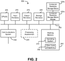
- FIG. 2 illustrates an exemplary computer system 200, in which various embodiments of the present invention may be implemented.
- the system 200 may be used to implement any of the computer systems described above.
- the computer system 200 is shown comprising hardware elements that may be electrically coupled via a bus 255.
- the hardware elements may include one or more central processing units (CPUs) 205, one or more input devices 210 (e.g., a mouse, a keyboard, etc.), and one or more output devices 215 (e.g., a display device, a printer, etc.).
- the computer system 200 may also include one or more storage device 220.
- storage device(s) 220 may be disk drives, optical storage devices, solid-state storage device such as a random access memory (“RAM”) and/or a read-only memory (“ROM”), which can be programmable, flash-updateable and/or the like.
- RAM random access memory
- ROM read-only memory
- the computer system 200 may additionally include a computer-readable storage media reader 225a, a communications system 230 (e.g., a modem, a network card (wireless or wired), an infra-red communication device, etc.), and working memory 240, which may include RAM and ROM devices as described above.
- the computer system 200 may also include a processing acceleration unit 235, which can include a DSP, a special-purpose processor and/or the like.
- the computer-readable storage media reader 225a can further be connected to a computer-readable storage medium 225b, together (and, optionally, in combination with storage device(s) 220) comprehensively representing remote, local, fixed, and/or removable storage devices plus storage media for temporarily and/or more permanently containing computer-readable information.
- the communications system 230 may permit data to be exchanged with the network 220 and/or any other computer described above with respect to the system 200.
- the computer system 200 may also comprise software elements, shown as being currently located within a working memory 240, including an operating system 245 and/or other code 250, such as an application program (which may be a client application, web browser, mid-tier application, RDBMS, etc.). It should be appreciated that alternate embodiments of a computer system 200 may have numerous variations from that described above. For example, customized hardware might also be used and/or particular elements might be implemented in hardware, software (including portable software, such as applets), or both. Further, connection to other computing devices such as network input/output devices may be employed.
- Software of computer system 200 may include code 250 for implementing embodiments of the present invention as described herein.
- FIG. 3 is a block diagram illustrating, at a high-level, functional components of a system for tracking a mobile device according to one embodiment of the present invention.
- the system 300 includes a mobile device 305 such as a cell phone, tablet computer, laptop or any other computing device such as described above.
- the mobile device 305 can comprise a device specifically designed for use in the system 300 and which can be conveniently worn or carried by a user.
- a special-purpose device may or may not include or provide features or functions generally associated with more general purpose mobile devices.
- the mobile device 305 can comprise a head-mounted device, with a form-factor similar to a miniature Bluetooth headset.
- Such a device in such a form-factor can contain sensors such as used by embodiments described herein as well as sufficient memory and CPU power to perform the calculations and other functions described below but onboard this miniature device (as opposed to a smart phone or other mobile device) and then communicate the information to a network either via a mobile phone or without one.
- sensors such as used by embodiments described herein as well as sufficient memory and CPU power to perform the calculations and other functions described below but onboard this miniature device (as opposed to a smart phone or other mobile device) and then communicate the information to a network either via a mobile phone or without one.
- other form-factors and various other implementations are contemplated and considered to be within the scope of the present invention.
- the wireless device 305 can be communicatively coupled with one or more communications networks 310.
- the network(s) 310 can include a cellular communications network and/or one or more other wired or wireless networks such as the Internet or another network as described above.
- Also connected with the network(s) 310 can be one or more servers 315 and other computers 325 or devices.
- the servers 315 can comprise any one or more computers such as described above performing one or more functions and/or providing one or more services related to locating and tracking the mobile device 305 as will be described herein.
- the servers 315 may maintain one or more databases 320 as noted above which can include information related to the location of the mobile device, subscribers of the services provided, policies such as access control policies, etc.
- the other computers 325 can comprise any of the variety of computing devices described above and may be used, for example, by an interested third party to locate and/or track, i.e., monitor, the location and movement of the mobile device 305.
- embodiments of the invention provide systems and methods for tracking the mobile device 305 using sensors within the device and without using external signals to determine location, velocity, or heading.
- This information can be used by the servers 315 and/or other computers 325 for the remote tracking of the user carrying the mobile device 305.
- Such application can include, but are not limited to, services provide by the servers 315 for remotely monitoring elderly at-home-users to measure their activity and insure their health and safety. These services can be provided to interested parties such as caretakers, healthcare professionals, relatives etc. through the other computers systems 325 through a subscription to the service and/or subject to various access controls as can be contemplated.
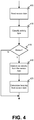
- FIG. 4 is a flowchart illustrating a process for tracking a mobile device according to one embodiment of the present invention.
- processing begins with reading 405 sensor data from each of a plurality of sensors within the mobile device.
- the sensors can provide the sensor data without relying on a signal from a device external to the mobile device.
- the plurality of sensors can comprise a compass, a gyroscope, and an accelerometer.
- Motion, velocity, and heading of the mobile device can be determined based on the sensor data. More specifically, determining motion, velocity, and heading of the mobile device based on the sensor data can comprise classifying 410 activity of the mobile device as motion or static.
- a velocity can be determined 420 for the mobile device based on the sensor data and a heading can be determined 425 for the mobile device based on the sensor data.
- This section addresses the issue of algorithmic differentiation of the type of activity that the user of the mobile device is currently engaging in. This capability can be used for a variety of applications from measuring and characterizing calorie consumption to fall detection, or instances in which the user may be incapacitated after a fall, for instance.
- Activity types can be classified into two categories, i.e., static and motion, with each of these categories divided into several sub-categories.
- the algorithm can differentiate between a person sitting still or standing still and differentiate both of those instances from the type of "behavior" measured when the mobile device is left lying on a shelf or desk.
- the motion category types identified by the algorithm can be differentiated between slow-walking, fast-walking and running.
- Embodiments of the present invention can implement a statistical machine learning approach based on data provided by the sensors in the mobile device (i.e. accelerometers, gyroscope, magnetometer, etc.). This data can be modeled to distinguish between these different activity types. To build this model, a set of n features can be analyzed. When plotted the analyzed data can be consistently accumulated (clustered) in different areas of the n-dimensional feature space in accordance with the different activities currently being performed (sitting, standing, walking etc.). An exemplary method to obtain such feature vectors can be summarized as follows:
- the first and third terms of the feature vector are simply the means of the NormUserAccel and NormGyro vectors respectively.
- the second term is the standard deviation of the NormUserAccel vector.
- FIG. 5 is a flowchart illustrating a process for classifying sensor data according to one embodiment of the present invention.
- classifying activity of the mobile device can comprise collecting 505 sensor data from each of the plurality of sensors over a time period.
- the sensor data can be fused 510 to produce estimates for each of a plurality of indications related to orientation of the mobile device.
- Each of the estimates can be normalized 515 and a plurality of vectors can be formed 520 representing activity of the mobile device based on the normalized estimates.
- the activity of the mobile device over the time period can then be classified 525 based on the plurality of vectors.
- a classification method can plot the data points on a 2-dimensional or 3-dimensional graphical representation.
- An exemplary algorithm is the k-Nearest Neighbors algorithm. This algorithm finds the k-nearest points to the new, unclassified point, where the measure of distance used is the Euclidean distance. Then the majority rule is applied, i.e. if that new, unclassified point is closer to more points in Group A than in Group B, then it will be classified as part of Group A.
- These groups can include any of the categories (i.e., motion or static) or subcategories mentioned above.
- embodiments of the present invention can proceed to determine the speed of the user.
- Embodiments described here can be used to differentiate the speed of the user while walking, as well as identify and differentiate between pedestrian and wheeled transportation methods (wheelchairs, bicycles etc.).
- these embodiments focus on determining velocity, when motion occurs, by analyzing specific data patterns provided by the sensors (accelerometer, gyroscope, magnetometer) to characterize patterns generated at different velocities.
- the machine learning algorithms can express these values, from repeated test trials, as data clusters, which make it possible to predict the velocity for each new data value.
- FIG. 6 illustrates the result of the machine learning algorithm that was used to characterize each of the data sets. For example, for a particular velocity, the mean and standard deviation of the readings from each of the accelerometers and gyroscopes can be used to characterize that velocity. These numbers can be collected in a feature vector. Each velocity can then be characterized by its unique feature vector cluster. This constitutes the reference data cluster 605, 610, or 615. When some new data 620 and 625 is collected, its characteristic feature vector can be calculated and then compared with the reference data set to determine velocity by assigning it to one of the reference data clusters 605, 610, 615.
- FIG. 7 is a flowchart illustrating a process for determining velocity according to one embodiment of the present invention.
- determining the velocity for the mobile device can comprise calculating 705 a mean and a standard deviation for each of a plurality of sensor data readings.
- a feature vector can be generated 710 based on each calculated mean and standard deviation.
- the generated feature vector can be compared 715 to a reference data set and each feature vector can be assigned 720 to a cluster based on said comparing.
- the velocity for the mobile device can then be determined 725 based on the clustered feature vector data.
- the process of assigning new values to one of the reference clusters can be accomplished using a variety of methods. Some, but not all, are described below.
- each velocity can be classified by a unique feature vector.
- each velocity can be classified by a cloud of points rather than a single one in feature space.
- the cloud for each velocity can be separated from the others in the high dimensional feature space and so when a new feature point is presented, its position with respect to a cloud, rather than a single point decides which velocity class it belongs to.
- clouds belonging to different velocities would be separable such that new data could be classified according to which cloud it is nearest to.
- K-nearest neighbors Given a training set cloud similar to described above, if a new test feature vector needs to be classified, its 'k' (where 'k' is some integer) nearest neighbors in the feature space are found. Depending on which class the majority of the 'k' neighbors belong to, the test feature vector can be classified accordingly.
- Naive Bayes Classification - Naive Bayes classifiers are statistical techniques built on Bayes' Theorem from probability. They assume that the presence (or absence) of a particular feature of a class is unrelated to the presence (or absence) of any other feature, given the class variable.
- Linear and Quadratic classifiers from MATLAB's Statistics Toolbox are conceptually similar techniques to those mentioned above with the point clouds in high dimensional feature space. They differ in the way the boundary between two clouds is decided. In the former the boundary is linear and in the latter the boundary is quadratic.
- Embodiments of the present invention can also account for the continuous velocity variations associated with pedestrian locomotion.
- a regression algorithm model can be implemented in order to enable the prediction of these continuous rather than discrete velocities.
- sets of features can be used to characterize the pattern of motion at a particular velocity. These features can include:
- the feature vector can be calculated (using the features corresponding to those used in the training set) and can be put into the different machine learning models to return the predicted velocity from each method.
- the features can be used in calculating the velocity value. Furthermore, the calculations were run with different combinations of these features to further refine the algorithm. In each case however, the model can include the data from all three axes in each of the feature groups mentioned above. This helps prevent the models from being biased towards a particular orientation of the devices. The following describes some possible the machine learning methods that can be used in developing these models.
- the training data for each velocity can be averaged to find the mean training velocity vector that characterized that particular velocity. In some sense, in high dimensional feature space, this would represent the cluster center of the particular velocity cluster. For a test feature vector, its Euclidean distance to each of the training cluster centers can be calculated. The cluster center that it is closest to can be predicted to be the velocity for that particular test feature vector.
- the training data can be distributed in high dimensional feature space as in the previous case.
- its nearest neighbors can be found and the velocity of the majority of those neighbors can be used as the predicted velocity of the particular test feature vector.
- Linear Classification This is an algorithm from the MATLAB library functions. It draws a linear discriminant boundary between the different training velocity clusters and predicts the velocity of a new test feature vector depending on which region it lies in, in the high dimensional feature space.
- Un-weighted Linear Regression This is a method in machine learning to essentially draw a line through the different clusters of the training data. Under certain statistical assumptions about the data, un-weighted linear regression results in the best fit line to the data (in higher dimensions it would not be a line but a hyper-plane).
- the training data represents motion at various velocities. Thus with the hyper-plane produced by linear regression it would be feasible to predict intermediate velocities with reasonable accuracy.
- Weighted Linear Regression This method theoretically accounts for variance that in some cases, severely affects the performance of linear regression. For instance, training clusters at different velocities might not be linearly related. So the best fit straight line for such data would not adequately capture the relationship in the data. Thus in weighted linear regression, when making predictions for a given test feature vector, the process is different. This method places more weight on those training samples that are closer (in some Euclidean sense) to the test feature vector and uses them as more important predictors than those samples that are farther away.
- the methods described here provided significantly more precise estimations of velocity over a range of velocities. Furthermore, the overall accuracy of the results, will improve as the database of training data is increased to take into consideration variations between individual body types and device placement on the subject's person.
- the heading algorithm can consider the device to be rotating when the magnitude of the angular velocity is above a certain threshold.
- the magnitude of the noise varies among the devices, so this threshold can be hard coded into the program based on examining a sample of the noise from each device or device type.
- this noise is still present when the device is rotating, so the heading will still drift over time.
- FIG. 8 is a flowchart illustrating a process for determining a heading according to one embodiment of the present invention.
- determining the heading for the mobile device can comprise determining 805 a magnitude of a set of angular velocity data.
- a determination 810 can be made as to whether the magnitude exceeds a pre-defined threshold.
- the mobile device can be considered 815 to be rotating.
- the sensor data can then be corrected 820 for drift over time and the corrected sensor data can be recorded 825 as a heading for the mobile device.
- the following methods can be used, after the initial estimate of heading is calculated, to help correct this drift.
- the heading can also be calculated by using the magnetometers of the mobile device to measure the Earth's magnetic field, which can then be used to find the device's absolute orientation.
- the problem with this approach is that the magnetometers pick up all magnetic fields, not just the Earth's, so there is a lot of noise in the readings due to magnetic fields generated by metals and electronic devices. This noise also varies greatly as the device changes its distance from these magnetic fields, so it is extremely difficult to filter out this noise, especially without some a priori knowledge of the magnetic fields present in the environment.
- the magnetometer does provide a signal that goes through a series of maximums and minimums as the device rotates. Since the largest component of the magnetic field present in most everyday environments is still the Earth's magnetic field, which is not changing, these extremes in the signal usually occur at the same orientation, i.e., if the magnetometer reading reaches a maximum at a heading of 135°, that reading will also be at a maximum the next time the device is at a heading of 135°. If an estimate of the heading has already been established, embodiments of the present invention can use the magnetometer reading to correct for drift by looking for extremes in the magnetometer readings. When a maximum is found, embodiments of the present invention can set the current heading equal to the heading of the device at the last maximum.
- One check can be expressed as: Is the initial estimate of the heading at the latest extreme within a certain tolerance of the heading found at the last similar extreme ("similar" extreme meaning that if at a maximum, look for the last maximum)? If the current heading differs from the last heading by a very large amount, greater than 30 degrees or so, it is likely that this difference is not due to drift. It is more likely that at least one of the two maximums in the magnetometer reading is a local maximum due to noise.
- This method takes advantage of the fact that people's movement is often restricted to fairly well-defined paths. For example, a person in an office building is bound to walk patterns constrained by the walls, hallways and other obstacles. As the algorithm tracks the subject's position and displacement, it can check the current estimate of position against the previously calculated positions. If the subject travels down a path that is similar in orientation and position to a path the subject has already taken, embodiments of the present invention can infer that this is a well-defined path the subject often takes, either due to physical restrictions, such as a hallway, or to habit or convention. Therefore, when estimating the subject's movement to be similar to a previously established pattern, embodiments of the present invention may assume the subject is actually repeating that same pattern and that any small differences in heading or position are errors.
- Embodiments of the present invention can also make adjustments to our location calculations based on assumptions about the way paths tend to be organized. For example, the hallways in an office building are likely to be either parallel or perpendicular to each other. It is especially unlikely for two hallways to be at a small angle to each other, like ten degrees.
- This means embodiments of the present invention can compare the heading of the user's current path to all the previous paths the user has taken. If the current path is close to parallel to a previous path, embodiments of the present invention can infer that the two paths are most likely supposed to be parallel and that the small difference in heading is due to drift, which embodiments of the present invention can correct.
- the biggest strength of the magnetometer method is that the assumptions that are made are more often valid than those in the environmental mapping method.
- the only assumption made is that the magnetic field in the environmental is fairly constant, with variations that are an order of magnitude smaller than the average strength of the field. Since the dominant magnetic field source in most everyday environments is the field of the Earth, which embodiments of the present invention an treat as constant (it is changing, but not quickly enough to be relevant to this application), this assumption is usually valid.
- the average person is still likely to occasionally experience large fluctuations in the magnetic field they are in, such as when they walk by a television that is turned on, but the safeguards described above seem to reliably ignore these events, as the raw data from the magnetometers were very noisy, but the algorithm did not misinterpret any of this noise.
- This section describes improvements to the heading algorithm so that it can estimate the path taken of a user carrying a device in his pocket (phone) or in a computer bag on his shoulder (tablet). With the device in the user's pocket, embodiments of the present invention can obtain an estimate of the heading if two conditions are met:
- embodiments of the present invention know that the two axes not aligned with gravity are in a horizontal plane, and embodiments of the present invention can use the magnetic readings on those axes to calculate a heading. Even if this heading is not the same as the actual heading of the user, it can still be used to draw the shape of the path taken if the difference between the user's heading and device's heading is constant.
- the raw heading can be calculated using the following logic:
- the two axes that aligned with the horizontal plane were identified by visually inspecting the gravity data collected on all three axes.
- the two that do not come near 1g are identified as the ones that cross the horizontal plane.
- This identification can be coded by taking the absolute value of the average of the gravity measured in the three axes and choosing the two axes with the smaller values.
- FIG. 9 is a flowchart illustrating a process for mapping location information according to one embodiment of the present invention.
- mapping the path of a mobile device can comprise identifying 905 each of a plurality of axes of a plane in which the mobile device is moving.
- a first heading vector along the identified axes and a second heading vector along the identified axes can be determined 910 and 915 based on the sensor data.
- the determined 910 and 915 heading vectors can be filtered 920 and a map of the path of the mobile device can be drawn 925 on the plane based on the filtered heading vectors.
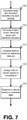
- FIG. 10 is a flowchart illustrating an exemplary process for filtering heading information according to one embodiment of the present invention.
- filtering the determined heading vectors can comprise storing 1005 the first heading vector as a third heading vector when a difference between the first heading vector and the second heading vector is determined to be large.
- the third heading vector can be copied 1010 to a fourth heading vector when a heading of a previous point is consistent with a heading of a current point.
- the first heading vector can be stored 1015 as a fifth heading vector when there is a large, consistent difference between the first heading vector and the fourth heading vector.
- Heading vectors that indicate quick changes can be discarded 1020 and gaps created by said discarding can be filled based on previous heading vectors and next heading vectors of the discarded heading vectors.
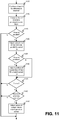
- FIG. 11 is a flowchart illustrating an exemplary process for drawing a map of location information according to one embodiment of the present invention.
- drawing the map of the path of the mobile device can comprise finding 1105 a current line of best fit for information received.
- the current line of best fit can be compared 1110 to previously saved lines.
- the current line of best fit can be adjusted 1120 to be parallel to the previously saved line.
- the position of the current line of best fit can be adjusted 1130 to match the position of the previously saved line.
- points of the current line of best fit can be adjusted 1145 to match points of the previously saved line.
- the algorithm can check several more conditions that help indicate how accurate the heading estimate is at that point. For example, it can check if the gravity signal on that axis is at a maximum. If it is, the device is as close to vertical as it will get for that particular step, which means that will probably provide the best heading estimate. If the gravity signal is not at a maximum, the heading estimate at that point can be ignored.
- the algorithm can also check the slope of the magnetic field strength signal. Theoretically, if the only magnetic field present were that of the Earth, the field strength should not change enough to be picked up by the magnetometers as the user walks around.
- the measured strength will almost always vary a small but significant amount, but if the strength quickly changes by a large amount, it is most likely due to a large noise source that will render the heading estimate unreliable. If the slope of the field strength is above a certain threshold, the heading at that point can be ignored.
- the strength of the field measured in the horizontal plane can also be checked because if the measurement on one of the axes is fluctuating between a positive and negative number, this can result in an unreliable heading measurement.
- the magnetometers on the horizontal axes are measuring magnetic field strengths of 1 uT and 1 uT, but one of the 1 uT readings sometimes bounces to -1 uT.
- the measured heading would be calculated as -90 - atan(1) , which is -135 degrees, but in the second scenario, the heading would be 90 - atan(-1) , which is 135 degrees. If the magnetic field strength in the horizontal plane is below a certain, threshold, then, embodiments of the present invention can ignore the heading calculation at that point.
- a moving median is the median of the collection of data points that surround the data point of interest. For example, considering the vector [7 3 11 -2 5 6] and taking the moving median of three data points at a time, the resulting vector would be [7 7 3 5 5 5] . For each data point, take the median of the sampling that consists of the point in question as well as the point before and after it, so for the third entry, 11, the median for that point is the median of the sample [3 11 -2]. For data points at the beginning and end of the first vector, where there are not enough surrounding data points to get a big enough sample size, the median of the closest data point with a big enough sample is substituted. For the first entry in the vector, 7, there is no data point before it, so the median of the next entry, 3, is used as the median for the first entry.
- embodiments of the present invention can assume that the user was on the same heading at both sections, so embodiments of the present invention can take the heading determined at that previous section and record it as the heading at the current index. It is important to make sure that the average is not changing too much at either point because the heading estimations are not very reliable when the signal is changing.
- This step is another attempt to undo the median filtering in cases where the changes that were filtered out were likely not noise.
- the raw heading will show a hump that gets removed by taking a moving median.
- the filtered heading and raw heading are superimposed, one sees that the raw heading signal constantly crosses the filtered heading signal, usually with every footstep. In this case, though, the hump stays on one side of the filtered heading for an unusually long time, on the order of two seconds.
- This blocks checks for such humps by keeping track of the area between the filtered and raw headings. If there is a section where the raw heading and filtered heading differ by a considerable amount for a long period of time, this section is probably indicative of a quick left-right or right-left, and the first heading estimate is restored.
- Embodiments of the present invention solve this problem by ignoring the heading calculations when the signal is changing very quickly and fill in the gaps by assigning the heading before the gap to the first half of the gap and the heading afterwards to the second half of the gap.
- Embodiments of the present invention determine whether the signal is changing too quickly by taking a moving average and comparing its slope at each point to a threshold value. For example, if the heading is 0 degrees at point 99 and 90 degrees and point 151 and the standard deviation for points 100 to 150 is above the threshold, points 100 to 125 will be given a heading of 0 and points 126 to 150 will be given a heading of 90.
- Finding Line of Best Fit As each new point is added to the map, the line of best fit for the current path is found. To find this line, two matrices are constructed. One is just a vertical vector containing the y-values of the coordinates. The second is matrix with two columns, where the first column contains ones and the second column contains the x-values of the coordinates. MATLAB has overloaded the backslash operator so that performing X ⁇ Y will return the matrix A, a 2x1 matrix where the first entry is the y-intercept and the second entry is the slope of the line of best fit.
- Start New Line of Best Fit The program has to be able to recognize when to end one line of best fit and start a new one to represent the path. There are two different ways the program determines that it is time to start a new line:
- the number of sample being used to calculate the line of best fit must meet a certain minimum before the algorithm decides to start a new line.
- the reason for this rule is that when trying to fit a line to a small number of data points, a bad fit often gets better as more data points are added, so if the number of points being fitted is less than min_samples, embodiments of the present invention can continue to add more data points to this fit even if the r 2 value is low.
- the paths taken would have headings of 0, 90, 180 and -90 degrees. It's possible that, while trying to map out a corner, the algorithm connects a 0 degree path and 90 degree path with a very short 60 degree line. Later on, as the user walks down the -90 degree path, the algorithm should not decide that this path is parallel to the 60 degree path because the 60 degree heading doesn't reflect anything about the actual path the user is taking. If a parallel line is found, the data points corresponding to the most recent line of best fit are rotated about the beginning point of the line to be exactly parallel with the older line.
- the algorithm can also check several conditions designed to determine if the two paths are in fact the same path.
- the conditions are (points A and B are endpoints of the new line; points 1 and 2 are endpoints of the previous line):
- condition (5) If any of conditions (1) to (4) are met and condition (5) is met, the two paths can be considered to be the same, and the coordinates contained in the new line can be snapped to the old line.
- a corner is defined as a point between two paths whose headings differ by at least 45 degrees. If the second-to-last endpoint is a corner, check if it is close to a previous corner and if the two corners have the same shape, i.e. is the heading of the path leading into corner 1 similar to the heading of the path leading into corner 2, and does the same apply for the paths coming after the corners? If so, the two corners are probably the same, and the points by the more recent corner can be shifted to match the previous corner. This is basically the same approach used to match the current path to previous paths, but because embodiments of the present invention are comparing shapes instead of just straight lines, it is less likely that the corner will get mistakenly identified as the same as another corner. That means that the tolerances used to compare the slopes and positions of two corners can be larger, which makes it possible to correct more extreme cases of drift.
- one embodiment of the present invention can include detecting aberrations in a magnetic field around the mobile device, augmenting the map of the path based the detected aberrations, wherein augmenting the map comprises adding one or more magnetic landmarks to the map based on the detected aberrations, and correcting a position estimate for the mobile device based on the augmented map and a currently detected aberration.
- machine-executable instructions may be stored on one or more machine readable mediums, such as CD-ROMs or other type of optical disks, floppy diskettes, ROMs, RAMs, EPROMs, EEPROMs, magnetic or optical cards, flash memory, or other types of machine-readable mediums suitable for storing electronic instructions.
- machine readable mediums such as CD-ROMs or other type of optical disks, floppy diskettes, ROMs, RAMs, EPROMs, EEPROMs, magnetic or optical cards, flash memory, or other types of machine-readable mediums suitable for storing electronic instructions.
- the methods may be performed by a combination of hardware and software.
Claims (8)
- Procédé de localisation et de suivi d'un dispositif mobile, le procédé comprenant :la lecture de données de capteur (405) à partir de chaque capteur parmi une pluralité de capteurs dans le dispositif mobile, la pluralité de capteurs comprenant un magnétomètre, un accéléromètre et un gyroscope ;la classification d'une activité (410) du dispositif mobile comme étant mobile ou statique ; eten réponse à la classification d'une activité du dispositif mobile comme étant mobile, la détermination (420) d'une vitesse du dispositif mobile, la classification d'une activité (410) du dispositif mobile comprenant :la collecte (505) de données de capteur à partir de chaque capteur parmi la pluralité de capteurs pendant une certaine période ;la fusion (510) des données de capteur pour produire des estimations pour chaque indication parmi une pluralité d'indications relatives à l'orientation et à l'accélération du dispositif mobile ;la normalisation (515) d'une estimation d'accélération et d'une estimation d'orientation ;la génération (520) d'un vecteur de caractéristiques en utilisant une pluralité de scalaires, la pluralité de scalaires comprenant l'estimation normalisée d'accélération et l'estimation normalisée d'orientation ;la comparaison (715) du vecteur de caractéristiques généré avec un ensemble de données de référence ;l'attribution (720) du vecteur de caractéristiques généré à un groupement de l'ensemble de données de référence en fonction de ladite comparaison ; etla détermination (725) d'une vitesse du dispositif mobile en fonction du groupement auquel le vecteur de caractéristiques généré est attribué, et la détermination (425) d'un cap du dispositif mobile en fonction des données de capteur.
- Procédé selon la revendication 1, dans lequel la détermination de la vitesse du dispositif mobile comprend :le calcul (705) d'une moyenne et d'un écart-type pour chaque lecture de données de capteur parmi une pluralité de lectures de données de capteur ; etla génération (710) du vecteur de caractéristiques en fonction de chaque moyenne et écart-type calculé.
- Procédé selon la revendication 1, dans lequel la détermination (425) d'un cap du dispositif mobile comprend :la détermination (805) d'une amplitude en fonction d'un ensemble de données de vitesse angulaire ;la détermination (810) selon laquelle l'amplitude dépasse un seuil prédéfini ; eten réponse à la détermination selon laquelle l'amplitude dépasse le seuil prédéfini, la classification (815) du dispositif mobile comme étant rotatif, la correction (820) de la dérive dans le temps des données de capteur collectées à partir du gyroscope, et l'enregistrement (825) des données de capteur corrigées en tant que cap du dispositif mobile.
- Procédé selon la revendication 1, comprenant en outre la cartographie d'un trajet du dispositif mobile,
la cartographie du trajet comprenant :l'identification (905) de chaque axe parmi une pluralité d'axes d'un plan dans lequel le dispositif mobile se déplace, le plan étant un plan horizontal identifié en fonction de données de gravité collectées le long de trois axes ;la détermination (910) d'un premier vecteur de cap le long des axes identifiés en fonction des données de capteur ;la détermination (915) d'un deuxième vecteur de cap le long des axes identifiés en fonction des données de capteur ;le filtrage (920) des vecteurs de cap déterminés ; etle traçage (925) d'une carte du trajet du dispositif mobile sur le plan en fonction des vecteurs de cap filtrés. - Procédé selon la revendication 4, dans lequel le traçage de la carte du trajet du dispositif mobile comprend les étapes suivantes :trouver (1105) une droite actuelle de meilleur ajustement pour un trajet actuel, le trajet actuel étant basé sur les vecteurs de cap filtrés ;comparer (1110) la droite actuelle de meilleur ajustement trouvée à des droites précédemment enregistrées ;en réponse à la détermination (1115) selon laquelle la droite actuelle de meilleur ajustement trouvée est quasiment parallèle à une droite précédemment enregistrée, ajuster (1120) la droite actuelle de meilleur ajustement trouvée pour qu'elle soit parallèle à la droite précédemment enregistrée ;en réponse à la détermination (1125) selon laquelle la droite actuelle de meilleur ajustement trouvée est située à une position proche de celle d'une droite précédemment enregistrée, ajuster (1130) la position de la droite actuelle de meilleur ajustement trouvée pour qu'elle corresponde à la position de la droite précédemment enregistrée ;en réponse à la détermination (1135) selon laquelle la droite actuelle de meilleur ajustement trouvée ajustée comprend un coin et en réponse à la détermination (1140) selon laquelle le coin de la droite actuelle de meilleur ajustement trouvée ajustée correspond à un coin d'une droite précédemment enregistrée, ajuster (1145) des points de la droite actuelle de meilleur ajustement trouvée ajustée pour correspondre à des points de la droite précédemment enregistrée, le traçage de la carte du trajet étant basé sur les points ajustés de la droite actuelle de meilleur ajustement trouvée ajustée.
- Procédé selon la revendication 4, comprenant en outre :la détection d'aberrations dans un champ magnétique autour du dispositif mobile ;l'augmentation de la carte du trajet en fonction des aberrations détectées, l'augmentation de la carte comprenant l'ajout d'un ou de plusieurs repères magnétiques sur la carte en fonction des aberrations détectées ; etla correction d'une estimation de position du dispositif mobile en fonction de la carte augmentée et d'une aberration actuellement détectée.
- Système (100, 200, 300) comprenant :un processeur (205) ; etune mémoire (240) couplée avec le processeur (205), et lisible par celui-ci, et stockant une séquence d'instructions qui, lorsqu'elle est exécutée par le processeur (205), entraîne la localisation et le suivi du dispositif mobile (305) par le processeur (205) de la manière suivante :en lisant des données de capteur à partir de chaque capteur parmi une pluralité de capteurs dans le dispositif mobile (305), la pluralité de capteurs comprenant un magnétomètre, un accéléromètre et un gyroscope ;en classant une activité du dispositif mobile comme étant mobile ou statique ; eten réponse à une classification d'une activité du dispositif mobile comme étant mobile, en déterminant une vitesse du dispositif mobile (305), la classification d'une activité (410) du dispositif mobile comprenant :la collecte de données de capteur à partir de chaque capteur parmi la pluralité de capteurs pendant une certaine période ;la fusion des données de capteur pour produire des estimations pour chaque indication parmi une pluralité d'indications relatives à l'orientation et à l'accélération du dispositif mobile (305) ;la normalisation d'une estimation d'accélération et d'une estimation d'orientation ;la génération d'un vecteur de caractéristiques en utilisant une pluralité de scalaires, la pluralité de scalaires comprenant l'estimation normalisée d'accélération et l'estimation normalisée d'orientation ;la comparaison du vecteur de caractéristiques généré avec un ensemble de données de référence ;l'attribution du vecteur de caractéristiques généré à un groupement de l'ensemble de données de référence en fonction de ladite comparaison ; etla détermination d'une vitesse en fonction du groupement auquel le vecteur de caractéristiques généré est attribué, et la détermination d'un cap du dispositif mobile (305) en fonction des données de capteur.
- Mémoire lisible par un ordinateur stockant une séquence d'instructions qui, lorsqu'elle est exécutée par un processeur (205), entraîne l'exécution par le processeur (205) du procédé selon l'une quelconque des revendications 1 à 6.
Applications Claiming Priority (3)
| Application Number | Priority Date | Filing Date | Title |
|---|---|---|---|
| US201161547969P | 2011-10-17 | 2011-10-17 | |
| US13/653,009 US8788193B2 (en) | 2011-10-17 | 2012-10-16 | Tracking activity, velocity, and heading using sensors in mobile devices or other systems |
| PCT/US2012/060509 WO2013059246A1 (fr) | 2011-10-17 | 2012-10-17 | Suivi d'activité, de vitesse et de cap à l'aide de capteurs dans des dispositifs mobiles ou autres systèmes |
Publications (3)
| Publication Number | Publication Date |
|---|---|
| EP2769574A1 EP2769574A1 (fr) | 2014-08-27 |
| EP2769574A4 EP2769574A4 (fr) | 2016-06-15 |
| EP2769574B1 true EP2769574B1 (fr) | 2019-01-02 |
Family
ID=48086547
Family Applications (1)
| Application Number | Title | Priority Date | Filing Date |
|---|---|---|---|
| EP12841080.0A Active EP2769574B1 (fr) | 2011-10-17 | 2012-10-17 | Suivi d'activité, de vitesse et de cap à l'aide de capteurs dans des dispositifs mobiles ou autres systèmes |
Country Status (4)
| Country | Link |
|---|---|
| US (1) | US8788193B2 (fr) |
| EP (1) | EP2769574B1 (fr) |
| CN (1) | CN104137594B (fr) |
| WO (1) | WO2013059246A1 (fr) |
Families Citing this family (33)
| Publication number | Priority date | Publication date | Assignee | Title |
|---|---|---|---|---|
| US8751151B2 (en) * | 2012-06-12 | 2014-06-10 | Trx Systems, Inc. | System and method for localizing a trackee at a location and mapping the location using inertial sensor information |
| US9395190B1 (en) * | 2007-05-31 | 2016-07-19 | Trx Systems, Inc. | Crowd sourced mapping with robust structural features |
| KR101960280B1 (ko) * | 2012-07-23 | 2019-03-20 | 삼성전자주식회사 | 자기장 지도를 수정하는 방법, 자기장 지도를 수정하는 사용자 단말 및 서버 |
| US20140143184A1 (en) * | 2012-11-21 | 2014-05-22 | Microsoft Corporation | Turn restriction inferencing |
| US9080878B2 (en) | 2013-02-21 | 2015-07-14 | Apple Inc. | Automatic identification of vehicle location |
| US11156464B2 (en) | 2013-03-14 | 2021-10-26 | Trx Systems, Inc. | Crowd sourced mapping with robust structural features |
| US11268818B2 (en) | 2013-03-14 | 2022-03-08 | Trx Systems, Inc. | Crowd sourced mapping with robust structural features |
| US9585768B2 (en) | 2013-03-15 | 2017-03-07 | DePuy Synthes Products, Inc. | Acetabular cup prosthesis alignment system and method |
| US9699739B2 (en) | 2013-06-07 | 2017-07-04 | Apple Inc. | Determination of device body location |
| US10716073B2 (en) * | 2013-06-07 | 2020-07-14 | Apple Inc. | Determination of device placement using pose angle |
| US9264862B2 (en) | 2013-08-15 | 2016-02-16 | Apple Inc. | Determining exit from a vehicle |
| US9305317B2 (en) | 2013-10-24 | 2016-04-05 | Tourmaline Labs, Inc. | Systems and methods for collecting and transmitting telematics data from a mobile device |
| US9363654B2 (en) | 2013-10-28 | 2016-06-07 | At&T Intellectual Property I, L.P. | Virtual historical displays |
| US9288630B2 (en) * | 2013-10-28 | 2016-03-15 | Verizon Patent And Licensing Inc. | Method and apparatus for providing positioning services using multi-spacing clustering |
| US9301082B2 (en) | 2013-12-06 | 2016-03-29 | Apple Inc. | Mobile device sensor data subscribing and sharing |
| US9360323B2 (en) | 2014-02-17 | 2016-06-07 | Tourmaline Labs, Inc. | Systems and methods for estimating movements of a vehicle using a mobile device |
| US10043112B2 (en) * | 2014-03-07 | 2018-08-07 | Qualcomm Incorporated | Photo management |
| GB201410612D0 (en) * | 2014-06-13 | 2014-07-30 | Tomtom Int Bv | Methods and systems for generating route data |
| CN105629324A (zh) * | 2014-12-01 | 2016-06-01 | 丰唐物联技术(深圳)有限公司 | 一种检测门开关状态的方法及装置 |
| US9544419B2 (en) * | 2014-12-24 | 2017-01-10 | Intel Corporation | Methods and systems for configuring a mobile device based on an orientation-based usage context |
| US9759561B2 (en) | 2015-01-06 | 2017-09-12 | Trx Systems, Inc. | Heading constraints in a particle filter |
| JP6644480B2 (ja) * | 2015-06-01 | 2020-02-12 | 株式会社イトーキ | 姿勢判別方法、姿勢判別プログラム、活動量計測方法、及び、活動量計測プログラム。 |
| US10438131B1 (en) * | 2015-12-14 | 2019-10-08 | Google Llc | Spherical random features for polynomial kernels |
| US10121374B2 (en) | 2016-06-10 | 2018-11-06 | Apple Inc. | Parking event detection and location estimation |
| US10003924B2 (en) | 2016-08-10 | 2018-06-19 | Yandex Europe Ag | Method of and server for processing wireless device sensor data to generate an entity vector associated with a physical location |
| US9924320B1 (en) | 2016-12-30 | 2018-03-20 | Uber Technologies, Inc. | Locating a user device |
| US11341512B2 (en) | 2018-12-20 | 2022-05-24 | Here Global B.V. | Distinguishing between pedestrian and vehicle travel modes by mining mix-mode trajectory probe data |
| US20220026461A1 (en) * | 2018-12-26 | 2022-01-27 | SWORD Health S.A. | Magnetometerless detection of incorrect attachment and calibration of motion tracking system |
| JP6804599B2 (ja) * | 2019-08-28 | 2020-12-23 | 株式会社イトーキ | 姿勢判別方法、姿勢判別プログラム、活動量計測方法、及び、活動量計測プログラム。 |
| US11715106B2 (en) | 2020-04-01 | 2023-08-01 | Mastercard International Incorporated | Systems and methods for real-time institution analysis based on message traffic |
| US11410178B2 (en) | 2020-04-01 | 2022-08-09 | Mastercard International Incorporated | Systems and methods for message tracking using real-time normalized scoring |
| CN111966130B (zh) * | 2020-06-28 | 2023-06-27 | 上海伊涵家居饰品有限公司 | 座椅自动归位控制方法、系统及其存储介质 |
| KR102576664B1 (ko) * | 2023-03-08 | 2023-09-13 | 스튜디오씨드코리아 주식회사 | 그래픽 사용자 인터페이스의 프로토타입 제작 방법 및 그 시스템 |
Family Cites Families (16)
| Publication number | Priority date | Publication date | Assignee | Title |
|---|---|---|---|---|
| US6195475B1 (en) | 1998-09-15 | 2001-02-27 | Hewlett-Packard Company | Navigation system for handheld scanner |
| JP3488144B2 (ja) * | 1999-08-24 | 2004-01-19 | 松下電器産業株式会社 | 位置通知装置 |
| US6522266B1 (en) * | 2000-05-17 | 2003-02-18 | Honeywell, Inc. | Navigation system, method and software for foot travel |
| US6826477B2 (en) * | 2001-04-23 | 2004-11-30 | Ecole Polytechnique Federale De Lausanne (Epfl) | Pedestrian navigation method and apparatus operative in a dead reckoning mode |
| US20050033200A1 (en) * | 2003-08-05 | 2005-02-10 | Soehren Wayne A. | Human motion identification and measurement system and method |
| CN1778598A (zh) * | 2004-11-17 | 2006-05-31 | 丰田自动车株式会社 | 电动汽车及其控制方法 |
| US7640148B2 (en) * | 2005-01-07 | 2009-12-29 | Gm Global Technology Operations, Inc. | Method of modeling vehicle parameter cycles |
| GB0515031D0 (en) | 2005-07-22 | 2005-08-31 | Univ Newcastle | Apparatus for determining the position of a moveable apparatus on a surface |
| US7561960B2 (en) * | 2006-04-20 | 2009-07-14 | Honeywell International Inc. | Motion classification methods for personal navigation |
| KR101239482B1 (ko) * | 2007-03-23 | 2013-03-06 | 퀄컴 인코포레이티드 | 멀티-센서 데이터 수집 및/또는 프로세싱 |
| AU2008283845A1 (en) * | 2007-08-06 | 2009-02-12 | Trx Systems, Inc. | Locating, tracking, and/or monitoring personnel and/or assets both indoors and outdoors |
| US10024676B2 (en) * | 2007-10-26 | 2018-07-17 | Tomtom Traffic B.V. | Method of processing positioning data |
| US9816821B2 (en) * | 2008-09-04 | 2017-11-14 | Apple Inc. | Location systems for handheld electronic devices |
| US8898034B2 (en) | 2009-06-03 | 2014-11-25 | Apple Inc. | Automatically identifying geographic direction |
| US20110238308A1 (en) | 2010-03-26 | 2011-09-29 | Isaac Thomas Miller | Pedal navigation using leo signals and body-mounted sensors |
| US8531180B2 (en) * | 2010-03-30 | 2013-09-10 | Apple Inc. | Determining heading using magnetometer data and angular rate data |
-
2012
- 2012-10-16 US US13/653,009 patent/US8788193B2/en active Active
- 2012-10-17 CN CN201280062283.1A patent/CN104137594B/zh active Active
- 2012-10-17 WO PCT/US2012/060509 patent/WO2013059246A1/fr active Application Filing
- 2012-10-17 EP EP12841080.0A patent/EP2769574B1/fr active Active
Non-Patent Citations (1)
| Title |
|---|
| None * |
Also Published As
| Publication number | Publication date |
|---|---|
| CN104137594B (zh) | 2018-03-02 |
| US8788193B2 (en) | 2014-07-22 |
| US20130096817A1 (en) | 2013-04-18 |
| EP2769574A4 (fr) | 2016-06-15 |
| WO2013059246A1 (fr) | 2013-04-25 |
| CN104137594A (zh) | 2014-11-05 |
| EP2769574A1 (fr) | 2014-08-27 |
Similar Documents
| Publication | Publication Date | Title |
|---|---|---|
| EP2769574B1 (fr) | Suivi d'activité, de vitesse et de cap à l'aide de capteurs dans des dispositifs mobiles ou autres systèmes | |
| Vlahogianni et al. | Driving analytics using smartphones: Algorithms, comparisons and challenges | |
| US10451744B2 (en) | Detecting user activity based on location data | |
| AU2015316575B2 (en) | Inertial tracking based determination of the position of a mobile device carried by a user in a geographical area | |
| US10496881B2 (en) | PU classifier for detection of travel mode associated with computing devices | |
| CN106682572B (zh) | 目标跟踪方法、系统和第一电子设备 | |
| US8892391B2 (en) | Activity detection | |
| US9730029B2 (en) | Unsupervised indoor localization and heading directions estimation | |
| Ahn et al. | RescueMe: An indoor mobile augmented-reality evacuation system by personalized pedometry | |
| EP3314205B1 (fr) | Technologies pour navigation à l'estimée pour piéton | |
| CN103340634B (zh) | 一种基于加速度变化检测人运动状态的方法 | |
| Zhang et al. | SmartMTra: Robust indoor trajectory tracing using smartphones | |
| US10401181B2 (en) | Detection of travel mode associated with computing devices | |
| Ren et al. | Movement pattern recognition assisted map matching for pedestrian/wheelchair navigation | |
| US20210396779A1 (en) | User posture transition detection and classification | |
| US20140309964A1 (en) | Internal Sensor Based Personalized Pedestrian Location | |
| CN103363990A (zh) | 信息处理装置、信息处理方法和程序 | |
| US20230314624A1 (en) | Device orientation initialization | |
| Yan et al. | FlexPDR: Fully flexible pedestrian dead reckoning using online multimode recognition and time-series decomposition | |
| US20190323842A1 (en) | Information processing apparatus, information processing method, and computer-readable recording medium recording information processing program | |
| Lopez et al. | Detecting changes of transportation-mode by using classification data | |
| Hemminki et al. | Gravity and linear acceleration estimation on mobile devices | |
| JP2016050868A (ja) | 行動推定装置、行動推定方法、および、行動推定プログラム | |
| Kamalian et al. | A survey on local transport mode detection on the edge | |
| Atashi | Multiple Model-based Indoor Localization via Bluetooth Low Energy and Inertial Measurement Unit Sensors |
Legal Events
| Date | Code | Title | Description |
|---|---|---|---|
| PUAI | Public reference made under article 153(3) epc to a published international application that has entered the european phase |
Free format text: ORIGINAL CODE: 0009012 |
|
| 17P | Request for examination filed |
Effective date: 20140513 |
|
| AK | Designated contracting states |
Kind code of ref document: A1 Designated state(s): AL AT BE BG CH CY CZ DE DK EE ES FI FR GB GR HR HU IE IS IT LI LT LU LV MC MK MT NL NO PL PT RO RS SE SI SK SM TR |
|
| DAX | Request for extension of the european patent (deleted) | ||
| RIC1 | Information provided on ipc code assigned before grant |
Ipc: H04W 4/04 20090101AFI20151021BHEP Ipc: H04W 4/02 20090101ALI20151021BHEP |
|
| RA4 | Supplementary search report drawn up and despatched (corrected) |
Effective date: 20160513 |
|
| RIC1 | Information provided on ipc code assigned before grant |
Ipc: H04W 4/04 20090101AFI20160509BHEP Ipc: H04W 4/02 20090101ALI20160509BHEP |
|
| STAA | Information on the status of an ep patent application or granted ep patent |
Free format text: STATUS: EXAMINATION IS IN PROGRESS |
|
| 17Q | First examination report despatched |
Effective date: 20170621 |
|
| REG | Reference to a national code |
Ref country code: DE Ref legal event code: R079 Ref document number: 602012055521 Country of ref document: DE Free format text: PREVIOUS MAIN CLASS: H04W0024000000 Ipc: H04W0004000000 |
|
| RIC1 | Information provided on ipc code assigned before grant |
Ipc: H04W 4/02 20090101ALI20180417BHEP Ipc: H04W 4/00 20090101AFI20180417BHEP |
|
| GRAP | Despatch of communication of intention to grant a patent |
Free format text: ORIGINAL CODE: EPIDOSNIGR1 |
|
| STAA | Information on the status of an ep patent application or granted ep patent |
Free format text: STATUS: GRANT OF PATENT IS INTENDED |
|
| INTG | Intention to grant announced |
Effective date: 20180720 |
|
| GRAS | Grant fee paid |
Free format text: ORIGINAL CODE: EPIDOSNIGR3 |
|
| GRAA | (expected) grant |
Free format text: ORIGINAL CODE: 0009210 |
|
| STAA | Information on the status of an ep patent application or granted ep patent |
Free format text: STATUS: THE PATENT HAS BEEN GRANTED |
|
| AK | Designated contracting states |
Kind code of ref document: B1 Designated state(s): AL AT BE BG CH CY CZ DE DK EE ES FI FR GB GR HR HU IE IS IT LI LT LU LV MC MK MT NL NO PL PT RO RS SE SI SK SM TR |
|
| REG | Reference to a national code |
Ref country code: GB Ref legal event code: FG4D |
|
| REG | Reference to a national code |
Ref country code: CH Ref legal event code: EP Ref country code: AT Ref legal event code: REF Ref document number: 1085992 Country of ref document: AT Kind code of ref document: T Effective date: 20190115 |
|
| REG | Reference to a national code |
Ref country code: IE Ref legal event code: FG4D |
|
| REG | Reference to a national code |
Ref country code: DE Ref legal event code: R096 Ref document number: 602012055521 Country of ref document: DE |
|
| REG | Reference to a national code |
Ref country code: NL Ref legal event code: MP Effective date: 20190102 |
|
| REG | Reference to a national code |
Ref country code: LT Ref legal event code: MG4D |
|
| REG | Reference to a national code |
Ref country code: AT Ref legal event code: MK05 Ref document number: 1085992 Country of ref document: AT Kind code of ref document: T Effective date: 20190102 |
|
| PG25 | Lapsed in a contracting state [announced via postgrant information from national office to epo] |
Ref country code: NL Free format text: LAPSE BECAUSE OF FAILURE TO SUBMIT A TRANSLATION OF THE DESCRIPTION OR TO PAY THE FEE WITHIN THE PRESCRIBED TIME-LIMIT Effective date: 20190102 |
|
| PG25 | Lapsed in a contracting state [announced via postgrant information from national office to epo] |
Ref country code: ES Free format text: LAPSE BECAUSE OF FAILURE TO SUBMIT A TRANSLATION OF THE DESCRIPTION OR TO PAY THE FEE WITHIN THE PRESCRIBED TIME-LIMIT Effective date: 20190102 Ref country code: SE Free format text: LAPSE BECAUSE OF FAILURE TO SUBMIT A TRANSLATION OF THE DESCRIPTION OR TO PAY THE FEE WITHIN THE PRESCRIBED TIME-LIMIT Effective date: 20190102 Ref country code: FI Free format text: LAPSE BECAUSE OF FAILURE TO SUBMIT A TRANSLATION OF THE DESCRIPTION OR TO PAY THE FEE WITHIN THE PRESCRIBED TIME-LIMIT Effective date: 20190102 Ref country code: PT Free format text: LAPSE BECAUSE OF FAILURE TO SUBMIT A TRANSLATION OF THE DESCRIPTION OR TO PAY THE FEE WITHIN THE PRESCRIBED TIME-LIMIT Effective date: 20190502 Ref country code: NO Free format text: LAPSE BECAUSE OF FAILURE TO SUBMIT A TRANSLATION OF THE DESCRIPTION OR TO PAY THE FEE WITHIN THE PRESCRIBED TIME-LIMIT Effective date: 20190402 Ref country code: LT Free format text: LAPSE BECAUSE OF FAILURE TO SUBMIT A TRANSLATION OF THE DESCRIPTION OR TO PAY THE FEE WITHIN THE PRESCRIBED TIME-LIMIT Effective date: 20190102 Ref country code: PL Free format text: LAPSE BECAUSE OF FAILURE TO SUBMIT A TRANSLATION OF THE DESCRIPTION OR TO PAY THE FEE WITHIN THE PRESCRIBED TIME-LIMIT Effective date: 20190102 |
|
| PG25 | Lapsed in a contracting state [announced via postgrant information from national office to epo] |
Ref country code: GR Free format text: LAPSE BECAUSE OF FAILURE TO SUBMIT A TRANSLATION OF THE DESCRIPTION OR TO PAY THE FEE WITHIN THE PRESCRIBED TIME-LIMIT Effective date: 20190403 Ref country code: BG Free format text: LAPSE BECAUSE OF FAILURE TO SUBMIT A TRANSLATION OF THE DESCRIPTION OR TO PAY THE FEE WITHIN THE PRESCRIBED TIME-LIMIT Effective date: 20190402 Ref country code: HR Free format text: LAPSE BECAUSE OF FAILURE TO SUBMIT A TRANSLATION OF THE DESCRIPTION OR TO PAY THE FEE WITHIN THE PRESCRIBED TIME-LIMIT Effective date: 20190102 Ref country code: IS Free format text: LAPSE BECAUSE OF FAILURE TO SUBMIT A TRANSLATION OF THE DESCRIPTION OR TO PAY THE FEE WITHIN THE PRESCRIBED TIME-LIMIT Effective date: 20190502 Ref country code: RS Free format text: LAPSE BECAUSE OF FAILURE TO SUBMIT A TRANSLATION OF THE DESCRIPTION OR TO PAY THE FEE WITHIN THE PRESCRIBED TIME-LIMIT Effective date: 20190102 Ref country code: LV Free format text: LAPSE BECAUSE OF FAILURE TO SUBMIT A TRANSLATION OF THE DESCRIPTION OR TO PAY THE FEE WITHIN THE PRESCRIBED TIME-LIMIT Effective date: 20190102 |
|
| REG | Reference to a national code |
Ref country code: DE Ref legal event code: R097 Ref document number: 602012055521 Country of ref document: DE |
|
| PG25 | Lapsed in a contracting state [announced via postgrant information from national office to epo] |
Ref country code: SK Free format text: LAPSE BECAUSE OF FAILURE TO SUBMIT A TRANSLATION OF THE DESCRIPTION OR TO PAY THE FEE WITHIN THE PRESCRIBED TIME-LIMIT Effective date: 20190102 Ref country code: CZ Free format text: LAPSE BECAUSE OF FAILURE TO SUBMIT A TRANSLATION OF THE DESCRIPTION OR TO PAY THE FEE WITHIN THE PRESCRIBED TIME-LIMIT Effective date: 20190102 Ref country code: RO Free format text: LAPSE BECAUSE OF FAILURE TO SUBMIT A TRANSLATION OF THE DESCRIPTION OR TO PAY THE FEE WITHIN THE PRESCRIBED TIME-LIMIT Effective date: 20190102 Ref country code: EE Free format text: LAPSE BECAUSE OF FAILURE TO SUBMIT A TRANSLATION OF THE DESCRIPTION OR TO PAY THE FEE WITHIN THE PRESCRIBED TIME-LIMIT Effective date: 20190102 Ref country code: DK Free format text: LAPSE BECAUSE OF FAILURE TO SUBMIT A TRANSLATION OF THE DESCRIPTION OR TO PAY THE FEE WITHIN THE PRESCRIBED TIME-LIMIT Effective date: 20190102 Ref country code: AT Free format text: LAPSE BECAUSE OF FAILURE TO SUBMIT A TRANSLATION OF THE DESCRIPTION OR TO PAY THE FEE WITHIN THE PRESCRIBED TIME-LIMIT Effective date: 20190102 Ref country code: IT Free format text: LAPSE BECAUSE OF FAILURE TO SUBMIT A TRANSLATION OF THE DESCRIPTION OR TO PAY THE FEE WITHIN THE PRESCRIBED TIME-LIMIT Effective date: 20190102 Ref country code: AL Free format text: LAPSE BECAUSE OF FAILURE TO SUBMIT A TRANSLATION OF THE DESCRIPTION OR TO PAY THE FEE WITHIN THE PRESCRIBED TIME-LIMIT Effective date: 20190102 |
|
| PLBE | No opposition filed within time limit |
Free format text: ORIGINAL CODE: 0009261 |
|
| STAA | Information on the status of an ep patent application or granted ep patent |
Free format text: STATUS: NO OPPOSITION FILED WITHIN TIME LIMIT |
|
| PG25 | Lapsed in a contracting state [announced via postgrant information from national office to epo] |
Ref country code: SM Free format text: LAPSE BECAUSE OF FAILURE TO SUBMIT A TRANSLATION OF THE DESCRIPTION OR TO PAY THE FEE WITHIN THE PRESCRIBED TIME-LIMIT Effective date: 20190102 |
|
| 26N | No opposition filed |
Effective date: 20191003 |
|
| PG25 | Lapsed in a contracting state [announced via postgrant information from national office to epo] |
Ref country code: SI Free format text: LAPSE BECAUSE OF FAILURE TO SUBMIT A TRANSLATION OF THE DESCRIPTION OR TO PAY THE FEE WITHIN THE PRESCRIBED TIME-LIMIT Effective date: 20190102 |
|
| PG25 | Lapsed in a contracting state [announced via postgrant information from national office to epo] |
Ref country code: TR Free format text: LAPSE BECAUSE OF FAILURE TO SUBMIT A TRANSLATION OF THE DESCRIPTION OR TO PAY THE FEE WITHIN THE PRESCRIBED TIME-LIMIT Effective date: 20190102 |
|
| REG | Reference to a national code |
Ref country code: DE Ref legal event code: R119 Ref document number: 602012055521 Country of ref document: DE |
|
| PG25 | Lapsed in a contracting state [announced via postgrant information from national office to epo] |
Ref country code: MC Free format text: LAPSE BECAUSE OF FAILURE TO SUBMIT A TRANSLATION OF THE DESCRIPTION OR TO PAY THE FEE WITHIN THE PRESCRIBED TIME-LIMIT Effective date: 20190102 |
|
| REG | Reference to a national code |
Ref country code: CH Ref legal event code: PL |
|
| PG25 | Lapsed in a contracting state [announced via postgrant information from national office to epo] |
Ref country code: CH Free format text: LAPSE BECAUSE OF NON-PAYMENT OF DUE FEES Effective date: 20191031 Ref country code: LI Free format text: LAPSE BECAUSE OF NON-PAYMENT OF DUE FEES Effective date: 20191031 Ref country code: DE Free format text: LAPSE BECAUSE OF NON-PAYMENT OF DUE FEES Effective date: 20200501 Ref country code: LU Free format text: LAPSE BECAUSE OF NON-PAYMENT OF DUE FEES Effective date: 20191017 |
|
| REG | Reference to a national code |
Ref country code: BE Ref legal event code: MM Effective date: 20191031 |
|
| PG25 | Lapsed in a contracting state [announced via postgrant information from national office to epo] |
Ref country code: BE Free format text: LAPSE BECAUSE OF NON-PAYMENT OF DUE FEES Effective date: 20191031 |
|
| GBPC | Gb: european patent ceased through non-payment of renewal fee |
Effective date: 20191017 |
|
| PG25 | Lapsed in a contracting state [announced via postgrant information from national office to epo] |
Ref country code: GB Free format text: LAPSE BECAUSE OF NON-PAYMENT OF DUE FEES Effective date: 20191017 Ref country code: IE Free format text: LAPSE BECAUSE OF NON-PAYMENT OF DUE FEES Effective date: 20191017 |
|
| PG25 | Lapsed in a contracting state [announced via postgrant information from national office to epo] |
Ref country code: CY Free format text: LAPSE BECAUSE OF FAILURE TO SUBMIT A TRANSLATION OF THE DESCRIPTION OR TO PAY THE FEE WITHIN THE PRESCRIBED TIME-LIMIT Effective date: 20190102 |
|
| PG25 | Lapsed in a contracting state [announced via postgrant information from national office to epo] |
Ref country code: MT Free format text: LAPSE BECAUSE OF FAILURE TO SUBMIT A TRANSLATION OF THE DESCRIPTION OR TO PAY THE FEE WITHIN THE PRESCRIBED TIME-LIMIT Effective date: 20190102 Ref country code: HU Free format text: LAPSE BECAUSE OF FAILURE TO SUBMIT A TRANSLATION OF THE DESCRIPTION OR TO PAY THE FEE WITHIN THE PRESCRIBED TIME-LIMIT; INVALID AB INITIO Effective date: 20121017 |
|
| PG25 | Lapsed in a contracting state [announced via postgrant information from national office to epo] |
Ref country code: MK Free format text: LAPSE BECAUSE OF FAILURE TO SUBMIT A TRANSLATION OF THE DESCRIPTION OR TO PAY THE FEE WITHIN THE PRESCRIBED TIME-LIMIT Effective date: 20190102 |
|
| P01 | Opt-out of the competence of the unified patent court (upc) registered |
Effective date: 20230724 |
|
| PGFP | Annual fee paid to national office [announced via postgrant information from national office to epo] |
Ref country code: FR Payment date: 20230911 Year of fee payment: 12 |