EP2769215B1 - Metering device for fluid- testing strips - Google Patents
Metering device for fluid- testing strips Download PDFInfo
- Publication number
- EP2769215B1 EP2769215B1 EP12840975.2A EP12840975A EP2769215B1 EP 2769215 B1 EP2769215 B1 EP 2769215B1 EP 12840975 A EP12840975 A EP 12840975A EP 2769215 B1 EP2769215 B1 EP 2769215B1
- Authority
- EP
- European Patent Office
- Prior art keywords
- test
- cartridge
- strips
- metering device
- array
- Prior art date
- Legal status (The legal status is an assumption and is not a legal conclusion. Google has not performed a legal analysis and makes no representation as to the accuracy of the status listed.)
- Active
Links
Images






Classifications
-
- B—PERFORMING OPERATIONS; TRANSPORTING
- B65—CONVEYING; PACKING; STORING; HANDLING THIN OR FILAMENTARY MATERIAL
- B65D—CONTAINERS FOR STORAGE OR TRANSPORT OF ARTICLES OR MATERIALS, e.g. BAGS, BARRELS, BOTTLES, BOXES, CANS, CARTONS, CRATES, DRUMS, JARS, TANKS, HOPPERS, FORWARDING CONTAINERS; ACCESSORIES, CLOSURES, OR FITTINGS THEREFOR; PACKAGING ELEMENTS; PACKAGES
- B65D83/00—Containers or packages with special means for dispensing contents
- B65D83/08—Containers or packages with special means for dispensing contents for dispensing thin flat articles in succession
- B65D83/0805—Containers or packages with special means for dispensing contents for dispensing thin flat articles in succession through an aperture in a wall
- B65D83/0811—Containers or packages with special means for dispensing contents for dispensing thin flat articles in succession through an aperture in a wall with means for assisting dispensing
- B65D83/0823—Containers or packages with special means for dispensing contents for dispensing thin flat articles in succession through an aperture in a wall with means for assisting dispensing the articles being pushed and slid through the aperture
- B65D83/0829—Containers or packages with special means for dispensing contents for dispensing thin flat articles in succession through an aperture in a wall with means for assisting dispensing the articles being pushed and slid through the aperture by means of an actuator
-
- B—PERFORMING OPERATIONS; TRANSPORTING
- B01—PHYSICAL OR CHEMICAL PROCESSES OR APPARATUS IN GENERAL
- B01L—CHEMICAL OR PHYSICAL LABORATORY APPARATUS FOR GENERAL USE
- B01L3/00—Containers or dishes for laboratory use, e.g. laboratory glassware; Droppers
-
- B—PERFORMING OPERATIONS; TRANSPORTING
- B01—PHYSICAL OR CHEMICAL PROCESSES OR APPARATUS IN GENERAL
- B01L—CHEMICAL OR PHYSICAL LABORATORY APPARATUS FOR GENERAL USE
- B01L9/00—Supporting devices; Holding devices
- B01L9/52—Supports specially adapted for flat sample carriers, e.g. for plates, slides, chips
-
- G—PHYSICS
- G01—MEASURING; TESTING
- G01N—INVESTIGATING OR ANALYSING MATERIALS BY DETERMINING THEIR CHEMICAL OR PHYSICAL PROPERTIES
- G01N33/00—Investigating or analysing materials by specific methods not covered by groups G01N1/00 - G01N31/00
- G01N33/48—Biological material, e.g. blood, urine; Haemocytometers
- G01N33/483—Physical analysis of biological material
- G01N33/487—Physical analysis of biological material of liquid biological material
- G01N33/4875—Details of handling test elements, e.g. dispensing or storage, not specific to a particular test method
- G01N33/48757—Test elements dispensed from a stack
-
- G—PHYSICS
- G01—MEASURING; TESTING
- G01N—INVESTIGATING OR ANALYSING MATERIALS BY DETERMINING THEIR CHEMICAL OR PHYSICAL PROPERTIES
- G01N35/00—Automatic analysis not limited to methods or materials provided for in any single one of groups G01N1/00 - G01N33/00; Handling materials therefor
-
- G—PHYSICS
- G01—MEASURING; TESTING
- G01N—INVESTIGATING OR ANALYSING MATERIALS BY DETERMINING THEIR CHEMICAL OR PHYSICAL PROPERTIES
- G01N35/00—Automatic analysis not limited to methods or materials provided for in any single one of groups G01N1/00 - G01N33/00; Handling materials therefor
- G01N35/00029—Automatic analysis not limited to methods or materials provided for in any single one of groups G01N1/00 - G01N33/00; Handling materials therefor provided with flat sample substrates, e.g. slides
- G01N35/00069—Automatic analysis not limited to methods or materials provided for in any single one of groups G01N1/00 - G01N33/00; Handling materials therefor provided with flat sample substrates, e.g. slides whereby the sample substrate is of the bio-disk type, i.e. having the format of an optical disk
-
- B—PERFORMING OPERATIONS; TRANSPORTING
- B01—PHYSICAL OR CHEMICAL PROCESSES OR APPARATUS IN GENERAL
- B01L—CHEMICAL OR PHYSICAL LABORATORY APPARATUS FOR GENERAL USE
- B01L2200/00—Solutions for specific problems relating to chemical or physical laboratory apparatus
- B01L2200/04—Exchange or ejection of cartridges, containers or reservoirs
-
- B—PERFORMING OPERATIONS; TRANSPORTING
- B01—PHYSICAL OR CHEMICAL PROCESSES OR APPARATUS IN GENERAL
- B01L—CHEMICAL OR PHYSICAL LABORATORY APPARATUS FOR GENERAL USE
- B01L2200/00—Solutions for specific problems relating to chemical or physical laboratory apparatus
- B01L2200/06—Fluid handling related problems
- B01L2200/0689—Sealing
-
- B—PERFORMING OPERATIONS; TRANSPORTING
- B01—PHYSICAL OR CHEMICAL PROCESSES OR APPARATUS IN GENERAL
- B01L—CHEMICAL OR PHYSICAL LABORATORY APPARATUS FOR GENERAL USE
- B01L2300/00—Additional constructional details
- B01L2300/08—Geometry, shape and general structure
- B01L2300/0809—Geometry, shape and general structure rectangular shaped
- B01L2300/0825—Test strips
-
- B—PERFORMING OPERATIONS; TRANSPORTING
- B01—PHYSICAL OR CHEMICAL PROCESSES OR APPARATUS IN GENERAL
- B01L—CHEMICAL OR PHYSICAL LABORATORY APPARATUS FOR GENERAL USE
- B01L2300/00—Additional constructional details
- B01L2300/12—Specific details about materials
- B01L2300/123—Flexible; Elastomeric
-
- G—PHYSICS
- G01—MEASURING; TESTING
- G01N—INVESTIGATING OR ANALYSING MATERIALS BY DETERMINING THEIR CHEMICAL OR PHYSICAL PROPERTIES
- G01N35/00—Automatic analysis not limited to methods or materials provided for in any single one of groups G01N1/00 - G01N33/00; Handling materials therefor
- G01N35/00029—Automatic analysis not limited to methods or materials provided for in any single one of groups G01N1/00 - G01N33/00; Handling materials therefor provided with flat sample substrates, e.g. slides
- G01N2035/00089—Magazines
-
- G—PHYSICS
- G01—MEASURING; TESTING
- G01N—INVESTIGATING OR ANALYSING MATERIALS BY DETERMINING THEIR CHEMICAL OR PHYSICAL PROPERTIES
- G01N35/00—Automatic analysis not limited to methods or materials provided for in any single one of groups G01N1/00 - G01N33/00; Handling materials therefor
- G01N35/00029—Automatic analysis not limited to methods or materials provided for in any single one of groups G01N1/00 - G01N33/00; Handling materials therefor provided with flat sample substrates, e.g. slides
- G01N2035/00099—Characterised by type of test elements
- G01N2035/00108—Test strips, e.g. paper
Definitions
- fluids may be tested for non-medical reasons, such as blood-alcohol testing in law enforcement.
- Several devices are currently available on the market for measuring aspects of body fluids, including devices that use electrochemical or photometric techniques, among other example techniques.
- electrochemical analyses input electrical signals are typically applied to fluids and resulting electrical signals are measured.
- photometric testing light signals are applied to fluids and resulting light signals are measured.
- Other testing such as wet chemical analysis, mass spectrometry, or droplet evaporation analysis may also be used to test fluids.
- a problem recognized by the present inventors in currently available fluid-testing systems is that they are bulky, difficult to use, and indiscreet. Additionally, fluid test strips in presently available systems are not effectively protected against contamination by dust, bacteria, fluid on adjacent test strips, and/or other particles.
- an example cartridge for test strips includes a support structure and a thin-walled housing encompassing the support structure.
- the support structure is configured to hold a sheet-like array comprising several test strips.
- the cartridge may be thin and may include mechanisms for dispensing test strips and sealing the test strips against contamination.
- an example metering device is configured to accommodate a thin, flat test strip holder and dispenser.
- the metering device includes an interface element (e.g., a button or switch) that allows a user to dispense test strips from the cartridge.
- the metering device may also include systems for testing the fluids on the test strips, and displaying results of the testing.
- a single interaction with the interface element may cause the metering device to trigger the test-strip dispensing, fluid metering, and displaying of results.
- Figures 1-4 illustrate example cartridge architectures.
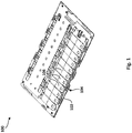
- Figure 1 shows an internal view of an example cartridge 100.
- cartridge 100 includes support structure 102 that holds array 104 of test strips (e.g., test strips 106).
- test strips 106 may be relatively flat, each having length and width that is much larger than the depth of each test strip.
- array 104 the test strips are laid with a thin side of each strip adjacent to a thin side of a neighboring strip (i.e., side-by-side rather than stacked on top of each other).
- array 104 is a thin, flat configuration that is sheet-like (i.e., thin and flat like a sheet of paper) in dimension.
- the particular arrangement shown in Figure 1 has the longer sides of each test strip placed directly adjacent to each other, other arrangements may place the test strips side-by-side in different ways.
- support structure 102 that holds array 104 may simply be an open channel in the housing into which test strips may be laid. Additionally, support structure 102 may include spring elements to hold the test strips in place to avoid disarrangement caused by the any open space in array 104.
- Figure 1 shows a particular number of test strips in array 104.
- this number of test strips is not essential and can vary according to the size of the cartridge, size of the metering device, and/or size of the test strips.
- a handheld cartridge may contain at least one array of 10-15 test strips.
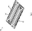
- Figure 2 shows a cartridge 200 that includes a second support structure 206 to support a second array of test strips 208, thereby holding 20-30 test strips.
- Other embodiments may support greater than two arrays of test strips or may support arrays of greater than 15 test strips.
- the second array of test strips 208 has roughly the same elements as first array 204, but second array 208 is oriented facing the opposite direction as first array 204.
- first array 204 were turned 180[deg.] around the geometric center of cartridge 200, then all the elements of the turned first array would be in the same position as corresponding elements in second array 208.
- the second array of test strips may be oriented in other ways with respect to the first array of test strips.
- each of the arrays may have different features and/or different numbers of test strips.
- cartridge 200 With a common size for test strips, the layout of cartridge 200 may result in about a credit-card-sized cartridge, making the cartridge convenient for pocketing.
- a cartridge In addition to holding test strips, a cartridge includes mechanisms for moving and dispensing the test strips.
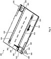
- Figure 3 shows elements that facilitate movement of array of test strips 204 held in cartridge 200.
- Figure 3 is an underside view of cartridge 200, showing housing 300 along with other elements that are accessible from the underside of cartridge 200.
- cartridge 200 includes an "ejector" 302 that, when actuated, applies pressure to test strip 304 in order to push test strip 304 at least partially through opening 308 in the direction indicated by arrow 306.
- the contacts of the electrical connectors from the metering device may interface with test strip 304 either on a portion of test strip 304 that has been pushed through opening 308 or on a portion exposed by opening 312.
- the electrical connectors may interface with electrical contacts on the test strip.
- the connectors may interface with a portion of the test strip that carries fluid. In either case, the electrical conductor may apply electrical signals to the captured fluids.
- the ejector may include features that can be caught, latched, pushed, pulled, held, actuated, or otherwise engaged to cause the ejector to dispense test strip 304.
- Such features may include, for example, grooves, indentations, holes, ridges, hooks, handles, buttons, teeth, knife-edges, among other examples. These features may be continuous across the underside or localized to certain areas. These features may be accessible through opening 312.
- test strips may include a capillary tube 310 that is operable to receive and convey the fluids to the electrical contact regions or to another area of measurement.
- the capillary tube may include a sharpened end so that blood or other internal fluids may be received directly into the test strip.
- Test strip 304 may then be removed from cartridge 200 through opening 308. Once test strip 304 is removed through opening 308, the next test strip in line may be moved into the vacancy left by test strip 304. In order to facilitate this movement, a slider 314 may be provided below the test strips so that array 204 may be moved together into a new position after test strip 304 is removed from cartridge 200. As shown, the tests-strips may move in the direction indicated by arrow 316 (called the transport direction) which is towards opening 308.
- This slider may also include hooks or barbs in order to prevent the test strips from moving in the direction opposite transport direction.
- the slider may also include features like those of the ejector that can be engaged by a user to move the slider from the outside of the cartridge.
- cartridge 200 may include elements for interacting with second array of test strips 208.
- cartridge 200 may include ejector 322, slider 324 and openings 326 and 328 that may function the same as the corresponding elements that interact with array 204.
- Figure 3 shows openings 318 and 330 for movement and interfacing with slider 314.
- a user may actuate the slider and ejector by, for example, sliding their finger across the features exposed by openings 312, 318, 328, and 330.
- the cartridge includes sealing structures that prevent ambient air from entering the cartridge.
- gaps between housing 300 and each of ejectors 302 and 322 may be sealed.
- gaps between housing 300 and sliders 314 and 324 may also be sealed.
- opening 308 may be sealed when not in use.
- Sealing structures may include labyrinth seals, elastomeric seals, and adhesive foil seals, among other examples.
- moving parts may be provisioned with specific features (e.g., glide ribs) to be movable across the adhesive surface without sticking.
- a cartridge may include one or more sliding seals that may seal and unseal in response to actuation.
- metal sliding seal 320 may open when ejector 302 pushes a test strip through opening 308. When no test strip is being pushed through opening 308, metal sliding seal 320 may be moved back in front of opening 308, sealing the opening.
- Such a sliding seal may also include any of the particular sealing structures described above, such as labyrinth, elastomeric or other sealing structures.
- a cartridge may include elastomeric layer 402 inside the first support structure 404 so that the capillary tube of each test strip (406A, 406B, and 406C) may be pressed into elastomeric layer 402. Elastomeric 402 may deform to accommodate the capillary tube of each test strip. In this way, any contamination that does enter the cartridge is kept out of the fluid test strip.
- the squeeze force of elastomeric layer 402 on test strips 406 may be partially equalized when the test strips move due to a sloped geometry of the rear supporting-wall in the cartridge.
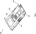
- top housing 500 may include viewing windows 502 to allow a user to visually check the status of the cartridge (e.g., how many test strips remain, whether the test strips are functional).
- viewing windows may be designed so that a particular part of the test strip may be seen through the windows.
- the test strips may be given marks along the portion of the test strips that is visible through the viewing windows. For example, a test strip may have a mark that changes color when fluid has been applied to the test strip.
- top housing 500 of cartridge 200 may be formed substantially out of a transparent material, so that test strips maybe visible without the need for windows 502.
- Figures 6-11 illustrate aspects of a metering device that is used with the above-described test-strip cartridge.
- metering device 600 may be designed to receive cartridge 200 into a cartridge bay 604.
- Figure 6 shows cartridge 200 protruding from cartridge bay 604.
- cartridge bay 604 may include spring elements and locking elements for receiving cartridge 200 and holding cartridge 200 fixed. In such an embodiment, cartridge bay 604 may also use the spring elements to eject cartridge 200.
- metering device 600 may include housing 602 and interface elements 606 for receiving user-input.
- interface elements 606 include a button that may be actuated to trigger internal mechanisms.
- user-input such a triggering may occur in response to a variety of input techniques.
- metering device 600 may respond to the actuation of button 608 in the same way regardless of whether a human, automated, or natural entity provides the force to actuate button 608.
- Other examples are also possible.
- other embodiments may include a variety of separate interface elements 606 to control particular functions of the metering device.
- metering device 600 may include display 610 for outputting the results of testing.
- Display 610 may include any standard display type (e.g., light-emitting diode array, liquid crystal display, etc.)
- Results of testing may be displayed as numbers, symbols, words, or other indicia and may the displayed results may describe various features of the tested liquid.
- the result may be a numerical representation of the concentration of glucose in the blood.
- the result may include other information, such as the units of concentration, whether the reported concentration is below a certain threshold level, etc.
- the result may be a numerical concentration result or a simple indication of whether the concentration is above or below a predefined concentration.
- display 610 may also indicate other information. For example, while the fluid on a test strip is being measured, display 610 may indicate that measurement is still under way, so that a user does not attempt to test the next strip prematurely.
- Figure 7 shows internal features of metering device 600, including a toothed gear-rack 702, a sliding lever 704 attached to a movable nut 706, metering and other electronics 708, and a battery 710. As will be explained, these and other elements may cause the movement, ejection, and measurement of test strips that are initially within an inserted cartridge.
- Figure 8 shows a magnified image of toothed gear-rack 702.
- the gear rack includes a set of ramp-shaped teeth 802, each tooth attached to a spring-element 804.
- Figure 9 shows toothed gear-rack 702 in place in metering device 600.
- gear-rack 702 may connect directly to button 608 so that, as button 608 is actuated by user-input, gear-rack 702 is also actuated.
- gear-rack 702 may initially slide up ramping surface 904A of an underlying support structure.
- gear-rack 702 may slide along flat surface 904B of the underlying support structure until button 608 reaches its maximum displacement.
- gear-rack 902 may slide back across flat surface 904B and down surface 904A in connection with button 608 moving back to its initial position.
- gear-rack 702 may cause the slider in the cartridge 200 to move array of test strips 204 towards opening 308.
- teeth 802 may engage with the features on the underside of slider 314 through opening 412.
- gear-rack 702 may be sufficiently below cartridge 200 that teeth 802 are not engaged with slider 314.
- cartridge 200 may be removed from metering device 600.
- gear-rack 702 moves up ramped surface 904A, teeth 802 may come in contact with and engage slider 314.
- gear-rack 702 moves across flat surface 904B, the engaged teeth 802 may push slider 314, along with array 204, towards opening 308.
- teeth 802 may disengage with slider 314 because of their ramped shape and because of the bending of spring elements 804. As gear-rack 702 moves back down ramped surface 904A, teeth 802 may move away from cartridge 200 until fully disengaged from slider 314.
- the length of the track on which button 608 moves i.e., the maximum distance that button 608 may move
- the strength of the spring elements used in the movable mechanisms may be chosen to minimize the force necessary for actuation of button 608.
- FIG. 10 shows a magnified view of lever 904 with the surrounding parts of metering device 600.
- slotted link 1002 also moves along the direction indicated by arrow 1004. This link may be part of gear-rack 702 or a separate piece that connects to the same interface element.
- Sliding lever 904 connects to slotted link 1002 by pin 1006, which impinges through the slot in slotted link 1002.
- pin 1006 For the first half of slotted link 904's forward movement, pin 1006 may be pushed in a downward direction (i.e., the direction away from gear-rack 702) due to the shape of sliding link 1002's slot. In turn, this force on pin 1006 may push lever 904 in an opposite direction along the direction indicated by arrow 1014.
- This lever actuates a movable nut 706, which includes a cam 1012 that may either engage or disengage with ejector 302 of cartridge 200 depending on the direction that cam 1012 is moving.
- cam 1012 when cam 1012 is moving upward (towards gear-rack 702), the cam does not engage with ejector 302. And, when cam 1012 is moving downward, the cam engages with ejector 302.
- the cam moves into place under ejector 302 without causing ejection.
- the slot may move along pin 1006 without affecting lever 904 because of the shape of the slot. Then, during the second half of the backward movement of sliding link 1002, cam 1012 engages with ejector 302 to cause cartridge 200 to eject a test strip.
- Cam 1012 is located on a spring feature that allows engagement and disengagement with the ejector 302 at a certain force.
- the dispensing step may cause the test strip to be completely ejected from the cartridge, thereby freeing up the dispensing position for the next actuation of button 608.
- a separate process may be used to remove a partially ejected test strip from the cartridge.
- Figures 8-10 show a particular way that each part may be moved to cause the movement and ejection of test strips
- lever 904 may be positioned to move in the necessary direction.
- ramp-shaped teeth 802 may be turned in the opposite direction to cause a movement of array 204 in the opposite direction. In such an embodiment, teeth 802 would not engage with the slider until the backward movement and the teeth would push the array away from opening 308.
- Other examples of variations are possible.
- gear-rack 702 and sliding link 1002 may not be physically connected to button 608. Rather, the actuation of button 608 may activate an electronic system that uses electrical motor, servos, or actuators to move gear-rack 702 and sliding link 1002. In this way, a user may supply only the force needed to activate the system, instead of supplying the mechanical force by actuating button 608.
- the test strip may be measured using fluid contacts 1016 and electronics 708.
- electronics 708 may provide electrical input signals to contacts 1016 and/or receive measurement signals from contacts 1016 to test the properties of fluids on the ejected test strip.
- Contacts 1016 may include electrical contacts for electrochemical analysis, such as a multi-pole connector to make electrical contact with the fluid on a test strip and relay signals to metering electronics in electronics 708.
- Electronics 708 may include circuits and systems for measuring, processing of results, displaying results, and/or communicate the data to a separate system. Battery 708 provides the necessary power to run the functions of electronics 708.
- contacts 1016 may include other types of interfaces for testing fluids.
- contacts 1016 may include photometric sensors, enzyme analyzers, or DNA testing systems, among other examples.
- electronics 708 and contacts 1016 may use any of the currently available methods for testing fluids, or any technique that will be made available hereafter.
- Metering device 600 can also include a secondary ejector for removing the test strip from the measuring position after the measurement is finished.
- a secondary ejector for removing the test strip from the measuring position after the measurement is finished.
- Such an ejector may discard the test strip either through an output opening in the metering device or into an area of metering device 600 that is designated for used test strips. In this way, the measurement area may be vacated in preparation for the next test strip.
- the secondary ejector may eject the measured test strip in response to the measurement electronics completing measurement. In other cases, the secondary ejector may activate along with the other mechanical elements when button 608 is actuated.
- Figure 11 shows an embodiment of metering device 600 that fully ejects a test strip 1102 through an opening 1104 in the housing of metering device 600.
- Figure 11 shows metering device 600 with the top housing removed.
- cartridge 200 is fully inserted into metering device 600 and actuation of button 608 has caused the internal mechanisms to eject test strip 1102.
- fluid may be received into test strip 1102 and electronics 708 may test the fluids and output the results. Then, test strip 1102 may be removed from cartridge 200 and metering device 600.
- metering device 600 may include viewing windows 1200 for checking on the status of test strips or system.
- the viewing windows 1200 on metering device 600 may be lined up with corresponding viewing windows 502 (or other transparent sections) on cartridge 200.
- larger portions of metering device 600 may be formed of transparent material.
Landscapes
- Health & Medical Sciences (AREA)
- Engineering & Computer Science (AREA)
- Life Sciences & Earth Sciences (AREA)
- Chemical & Material Sciences (AREA)
- Physics & Mathematics (AREA)
- Biomedical Technology (AREA)
- General Health & Medical Sciences (AREA)
- General Physics & Mathematics (AREA)
- Immunology (AREA)
- Pathology (AREA)
- Biochemistry (AREA)
- Analytical Chemistry (AREA)
- Clinical Laboratory Science (AREA)
- Chemical Kinetics & Catalysis (AREA)
- Optics & Photonics (AREA)
- Molecular Biology (AREA)
- Urology & Nephrology (AREA)
- Food Science & Technology (AREA)
- Medicinal Chemistry (AREA)
- Hematology (AREA)
- Biophysics (AREA)
- Mechanical Engineering (AREA)
- Automatic Analysis And Handling Materials Therefor (AREA)
- Investigating Or Analysing Materials By The Use Of Chemical Reactions (AREA)
- Investigating Or Analysing Biological Materials (AREA)
Description
- This application claims priority to
U.S. Provisional Application No. 61/549,382 filed on October 20, 2011 - Various medical conditions and treatments require the occasional testing of body fluids, such as blood, in order to monitor general health and effects of treatment.
- Additionally, fluids may be tested for non-medical reasons, such as blood-alcohol testing in law enforcement. Several devices are currently available on the market for measuring aspects of body fluids, including devices that use electrochemical or photometric techniques, among other example techniques. In electrochemical analyses, input electrical signals are typically applied to fluids and resulting electrical signals are measured. In photometric testing, light signals are applied to fluids and resulting light signals are measured. Other testing such as wet chemical analysis, mass spectrometry, or droplet evaporation analysis may also be used to test fluids.
- Metering devices and cartridges for fluid-testing are disclosed in
US 6,534,017 B1 ,US 6,176,119 B1 ,US 2008/817354 A1 ,US 2009/008395 A1 ,US 2008/181818 A1 ,US 2003/116583 A1 ,US 2008/164280 A1 andEP 1 531 934 A2 . - A problem recognized by the present inventors in currently available fluid-testing systems is that they are bulky, difficult to use, and indiscreet. Additionally, fluid test strips in presently available systems are not effectively protected against contamination by dust, bacteria, fluid on adjacent test strips, and/or other particles.
- The invention provides a metering device according to claim 1. In one embodiment, an example cartridge for test strips includes a support structure and a thin-walled housing encompassing the support structure. The support structure is configured to hold a sheet-like array comprising several test strips. The cartridge may be thin and may include mechanisms for dispensing test strips and sealing the test strips against contamination.
- In another embodiment, an example metering device is configured to accommodate a thin, flat test strip holder and dispenser. The metering device includes an interface element (e.g., a button or switch) that allows a user to dispense test strips from the cartridge. The metering device may also include systems for testing the fluids on the test strips, and displaying results of the testing. In some implementations, a single interaction with the interface element may cause the metering device to trigger the test-strip dispensing, fluid metering, and displaying of results.
-
-
FIG. 1 shows an example cartridge holding an example array of test strips. -
FIG. 2 shows an example cartridge holding multiple arrays of test strips. -
FIG. 3 shows an external view of the underside of an example cartridge in the process of dispensing a test strip. -
FIG. 4 shows an example array of test strips interfacing with an elastomeric seal. -
FIG. 5 shows an example top housing of a cartridge. -
FIG. 6 shows an example metering device receiving a cartridge. -
FIG. 7 shows an example toothed gear-rack. -
FIG. 8 shows internal mechanisms of an example metering device. -
FIG. 9 shows internal mechanisms of an example metering device. -
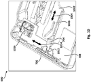
FIG. 10 shows internal mechanisms of an example metering device. -
FIG. 11 shows an example metering device holding an example cartridge. -
FIG. 12 shows external features of an example metering device. -
Figures 1-4 illustrate example cartridge architectures.Figure 1 shows an internal view of anexample cartridge 100. As shown,cartridge 100 includessupport structure 102 that holdsarray 104 of test strips (e.g., test strips 106). As shown,test strips 106 may be relatively flat, each having length and width that is much larger than the depth of each test strip. Inarray 104, the test strips are laid with a thin side of each strip adjacent to a thin side of a neighboring strip (i.e., side-by-side rather than stacked on top of each other). In this way,array 104 is a thin, flat configuration that is sheet-like (i.e., thin and flat like a sheet of paper) in dimension. Although the particular arrangement shown inFigure 1 has the longer sides of each test strip placed directly adjacent to each other, other arrangements may place the test strips side-by-side in different ways. - In some cases,
support structure 102 that holdsarray 104 may simply be an open channel in the housing into which test strips may be laid. Additionally,support structure 102 may include spring elements to hold the test strips in place to avoid disarrangement caused by the any open space inarray 104. -
Figure 1 shows a particular number of test strips inarray 104. However, this number of test strips is not essential and can vary according to the size of the cartridge, size of the metering device, and/or size of the test strips. For example, a handheld cartridge may contain at least one array of 10-15 test strips. As another example,Figure 2 shows acartridge 200 that includes asecond support structure 206 to support a second array oftest strips 208, thereby holding 20-30 test strips. Other embodiments may support greater than two arrays of test strips or may support arrays of greater than 15 test strips. As shown inFigure 2 , the second array oftest strips 208 has roughly the same elements asfirst array 204, butsecond array 208 is oriented facing the opposite direction asfirst array 204. In particular, iffirst array 204 were turned 180[deg.] around the geometric center ofcartridge 200, then all the elements of the turned first array would be in the same position as corresponding elements insecond array 208. In other embodiments, the second array of test strips may be oriented in other ways with respect to the first array of test strips. Further, in some embodiments, each of the arrays may have different features and/or different numbers of test strips. - With a common size for test strips, the layout of
cartridge 200 may result in about a credit-card-sized cartridge, making the cartridge convenient for pocketing. - In addition to holding test strips, a cartridge includes mechanisms for moving and dispensing the test strips.
Figure 3 shows elements that facilitate movement of array oftest strips 204 held incartridge 200. In particular,Figure 3 is an underside view ofcartridge 200, showinghousing 300 along with other elements that are accessible from the underside ofcartridge 200. As shown,cartridge 200 includes an "ejector" 302 that, when actuated, applies pressure to teststrip 304 in order to pushtest strip 304 at least partially through opening 308 in the direction indicated byarrow 306. Withtest strip 304 in this position, the contacts of the electrical connectors from the metering device may interface withtest strip 304 either on a portion oftest strip 304 that has been pushed through opening 308 or on a portion exposed by opening 312. In some cases, the electrical connectors may interface with electrical contacts on the test strip. In other cases, the connectors may interface with a portion of the test strip that carries fluid. In either case, the electrical conductor may apply electrical signals to the captured fluids. - Although not particularly shown, the ejector may include features that can be caught, latched, pushed, pulled, held, actuated, or otherwise engaged to cause the ejector to dispense
test strip 304. Such features may include, for example, grooves, indentations, holes, ridges, hooks, handles, buttons, teeth, knife-edges, among other examples. These features may be continuous across the underside or localized to certain areas. These features may be accessible through opening 312. - In order to facilitate capturing fluids, test strips may include a
capillary tube 310 that is operable to receive and convey the fluids to the electrical contact regions or to another area of measurement. In some cases, the capillary tube may include a sharpened end so that blood or other internal fluids may be received directly into the test strip. Whentest strip 304 is in the position shown inFigure 3 , fluids may be extracted and received intocapillary tube 310 and electrical connectors may be connected to the fluid for testing. -
Test strip 304 may then be removed fromcartridge 200 throughopening 308. Oncetest strip 304 is removed throughopening 308, the next test strip in line may be moved into the vacancy left bytest strip 304. In order to facilitate this movement, aslider 314 may be provided below the test strips so thatarray 204 may be moved together into a new position aftertest strip 304 is removed fromcartridge 200. As shown, the tests-strips may move in the direction indicated by arrow 316 (called the transport direction) which is towardsopening 308. - This slider may also include hooks or barbs in order to prevent the test strips from moving in the direction opposite transport direction. On the underside of the cartridge, the slider may also include features like those of the ejector that can be engaged by a user to move the slider from the outside of the cartridge.
- As also shown in
Figure 3 ,cartridge 200 may include elements for interacting with second array oftest strips 208. In particular,cartridge 200 may includeejector 322,slider 324 andopenings array 204. - In addition to
openings Figure 3 showsopenings slider 314. When used without a metering device, a user may actuate the slider and ejector by, for example, sliding their finger across the features exposed byopenings openings housing 300 and each ofejectors openings housing 300 andsliders - To seal some openings (e.g.,
openings 308 and 326), a cartridge may include one or more sliding seals that may seal and unseal in response to actuation. For example,metal sliding seal 320 may open whenejector 302 pushes a test strip throughopening 308. When no test strip is being pushed throughopening 308,metal sliding seal 320 may be moved back in front ofopening 308, sealing the opening. Such a sliding seal may also include any of the particular sealing structures described above, such as labyrinth, elastomeric or other sealing structures. - In addition to sealing the housing of the cartridge, the individual test strips may also be sealed against contamination. As shown in
Figure 4 , a cartridge may includeelastomeric layer 402 inside thefirst support structure 404 so that the capillary tube of each test strip (406A, 406B, and 406C) may be pressed intoelastomeric layer 402.Elastomeric 402 may deform to accommodate the capillary tube of each test strip. In this way, any contamination that does enter the cartridge is kept out of the fluid test strip. The squeeze force ofelastomeric layer 402 on test strips 406 may be partially equalized when the test strips move due to a sloped geometry of the rear supporting-wall in the cartridge. -
Figure 5 shows thetop housing 500 ofcartridge 200. As shown,top housing 500 may includeviewing windows 502 to allow a user to visually check the status of the cartridge (e.g., how many test strips remain, whether the test strips are functional). In some cases, viewing windows may be designed so that a particular part of the test strip may be seen through the windows. In some embodiments, the test strips may be given marks along the portion of the test strips that is visible through the viewing windows. For example, a test strip may have a mark that changes color when fluid has been applied to the test strip. In still other embodiments,top housing 500 ofcartridge 200 may be formed substantially out of a transparent material, so that test strips maybe visible without the need forwindows 502. -
Figures 6-11 illustrate aspects of a metering device that is used with the above-described test-strip cartridge. - As shown in
Figure 6 ,metering device 600 may be designed to receivecartridge 200 into acartridge bay 604.Figure 6 showscartridge 200 protruding fromcartridge bay 604. An example embodiment, though, may receive cartridge fully intocartridge bay 604. In some embodiments,cartridge bay 604 may include spring elements and locking elements for receivingcartridge 200 and holdingcartridge 200 fixed. In such an embodiment,cartridge bay 604 may also use the spring elements to ejectcartridge 200. - Also as shown in
Figure 6 ,metering device 600 may includehousing 602 andinterface elements 606 for receiving user-input. In particular,interface elements 606 include a button that may be actuated to trigger internal mechanisms. Although referred to as "user-input" such a triggering may occur in response to a variety of input techniques. For example,metering device 600 may respond to the actuation ofbutton 608 in the same way regardless of whether a human, automated, or natural entity provides the force to actuatebutton 608. Other examples are also possible. In addition to an implementation with asingle button 608, other embodiments may include a variety ofseparate interface elements 606 to control particular functions of the metering device. - Further, as shown in
Figure 6 ,metering device 600 may includedisplay 610 for outputting the results of testing.Display 610 may include any standard display type (e.g., light-emitting diode array, liquid crystal display, etc.) Results of testing may be displayed as numbers, symbols, words, or other indicia and may the displayed results may describe various features of the tested liquid. For example, if the metering device tests for blood-glucose levels, the result may be a numerical representation of the concentration of glucose in the blood. Alternatively, the result may include other information, such as the units of concentration, whether the reported concentration is below a certain threshold level, etc. As another example, if the test is for concentration of alcohol in saliva, the result may be a numerical concentration result or a simple indication of whether the concentration is above or below a predefined concentration. In addition to results,display 610 may also indicate other information. For example, while the fluid on a test strip is being measured,display 610 may indicate that measurement is still under way, so that a user does not attempt to test the next strip prematurely. -
Figure 7 shows internal features ofmetering device 600, including a toothed gear-rack 702, a slidinglever 704 attached to amovable nut 706, metering andother electronics 708, and abattery 710. As will be explained, these and other elements may cause the movement, ejection, and measurement of test strips that are initially within an inserted cartridge. -
Figure 8 shows a magnified image of toothed gear-rack 702. As shown, the gear rack includes a set of ramp-shapedteeth 802, each tooth attached to a spring-element 804.Figure 9 shows toothed gear-rack 702 in place inmetering device 600. Inmetering device 600, gear-rack 702 may connect directly tobutton 608 so that, asbutton 608 is actuated by user-input, gear-rack 702 is also actuated. As shown bymovement arrow 902, gear-rack 702 may initially slide up rampingsurface 904A of an underlying support structure. Then, as shown bymovement arrow 906, gear-rack 702 may slide alongflat surface 904B of the underlying support structure untilbutton 608 reaches its maximum displacement. Then, gear-rack 902 may slide back acrossflat surface 904B and downsurface 904A in connection withbutton 608 moving back to its initial position. - If
cartridge 200 is held incartridge bay 604, then the motion of gear-rack 702 may cause the slider in thecartridge 200 to move array oftest strips 204 towardsopening 308. In particular,teeth 802 may engage with the features on the underside ofslider 314 through opening 412. Whenbutton 608 is in its initial position, gear-rack 702 may be sufficiently belowcartridge 200 thatteeth 802 are not engaged withslider 314. In such a situation,cartridge 200 may be removed frommetering device 600. As gear-rack 702 moves up rampedsurface 904A,teeth 802 may come in contact with and engageslider 314. Then, as gear-rack 702 moves acrossflat surface 904B, the engagedteeth 802 may pushslider 314, along witharray 204, towardsopening 308. Asbutton 608 and gear-rack 702 move back to their initial positions,teeth 802 may disengage withslider 314 because of their ramped shape and because of the bending ofspring elements 804. As gear-rack 702 moves back down rampedsurface 904A,teeth 802 may move away fromcartridge 200 until fully disengaged fromslider 314. - Various considerations may be taken into account in designing the interface element and gear-rack system. For example, the length of the track on which
button 608 moves (i.e., the maximum distance thatbutton 608 may move) may be selected, based on the size of the test strips, to ensure thatarray 204 only moves the width of one test strip whenbutton 608 is actuated. Additionally, the strength of the spring elements used in the movable mechanisms may be chosen to minimize the force necessary for actuation ofbutton 608. - In addition to moving gear-
rack 702, actuation ofbutton 608 may move sliding lever 904. To illustrate,Figure 10 shows a magnified view of lever 904 with the surrounding parts ofmetering device 600. Whenbutton 608 is actuated, slottedlink 1002 also moves along the direction indicated byarrow 1004. This link may be part of gear-rack 702 or a separate piece that connects to the same interface element. Sliding lever 904 connects to slottedlink 1002 bypin 1006, which impinges through the slot in slottedlink 1002. - For the first half of slotted link 904's forward movement,
pin 1006 may be pushed in a downward direction (i.e., the direction away from gear-rack 702) due to the shape of slidinglink 1002's slot. In turn, this force onpin 1006 may push lever 904 in an opposite direction along the direction indicated byarrow 1014. This lever actuates amovable nut 706, which includes acam 1012 that may either engage or disengage withejector 302 ofcartridge 200 depending on the direction thatcam 1012 is moving. In particular, whencam 1012 is moving upward (towards gear-rack 702), the cam does not engage withejector 302. And, whencam 1012 is moving downward, the cam engages withejector 302. Hence, during the first half of the forward movement of slidinglink 1002, the cam moves into place underejector 302 without causing ejection. - For the second half of the forward movement and the first half of the backward movement, the slot may move along
pin 1006 without affecting lever 904 because of the shape of the slot. Then, during the second half of the backward movement of slidinglink 1002,cam 1012 engages withejector 302 to causecartridge 200 to eject a test strip.Cam 1012 is located on a spring feature that allows engagement and disengagement with theejector 302 at a certain force. When combined with the movement of gear-rack 702, the effect of a single stroke ofbutton 608 is that a test strip is pushed into a dispensing position and is then dispensed into a measuring position. In some cases, the dispensing step may cause the test strip to be completely ejected from the cartridge, thereby freeing up the dispensing position for the next actuation ofbutton 608. In other cases, a separate process may be used to remove a partially ejected test strip from the cartridge. - Although
Figures 8-10 show a particular way that each part may be moved to cause the movement and ejection of test strips, other example implementations may be used. For example, if a cartridge is designed so that a user must push theejector 302 in a different direction to eject a test strip, then lever 904 may be positioned to move in the necessary direction. As another example, ramp-shapedteeth 802 may be turned in the opposite direction to cause a movement ofarray 204 in the opposite direction. In such an
embodiment,teeth 802 would not engage with the slider until the backward movement and the teeth would push the array away from opening 308. Other examples of variations are possible. - Additionally, in some cases, gear-
rack 702 and slidinglink 1002 may not be physically connected tobutton 608. Rather, the actuation ofbutton 608 may activate an electronic system that uses electrical motor, servos, or actuators to move gear-rack 702 and slidinglink 1002. In this way, a user may supply only the force needed to activate the system, instead of supplying the mechanical force by actuatingbutton 608. - Once ejected, the test strip may be measured using
fluid contacts 1016 andelectronics 708. In particular,electronics 708 may provide electrical input signals tocontacts 1016 and/or receive measurement signals fromcontacts 1016 to test the properties of fluids on the ejected test strip.Contacts 1016 may include electrical contacts for electrochemical analysis, such as a multi-pole connector to make electrical contact with the fluid on a test strip and relay signals to metering electronics inelectronics 708.Electronics 708 may include circuits and systems for measuring, processing of results, displaying results, and/or communicate the data to a separate system.Battery 708 provides the necessary power to run the functions ofelectronics 708. In some embodiments,contacts 1016 may include other types of interfaces for testing fluids. For example,contacts 1016 may include photometric sensors, enzyme analyzers, or DNA testing systems, among other examples. For measuring and processing results,electronics 708 andcontacts 1016 may use any of the currently available methods for testing fluids, or any technique that will be made available hereafter. -
Metering device 600 can also include a secondary ejector for removing the test strip from the measuring position after the measurement is finished. Such an ejector may discard the test strip either through an output opening in the metering device or into an area ofmetering device 600 that is designated for used test strips. In this way, the measurement area may be vacated in preparation for the next test strip. The secondary ejector may eject the measured test strip in response to the measurement electronics completing measurement. In other cases, the secondary ejector may activate along with the other mechanical elements whenbutton 608 is actuated. - As an example,
Figure 11 shows an embodiment ofmetering device 600 that fully ejects atest strip 1102 through anopening 1104 in the housing ofmetering device 600. In particular,Figure 11 showsmetering device 600 with the top housing removed. InFigure 11 ,cartridge 200 is fully inserted intometering device 600 and actuation ofbutton 608 has caused the internal mechanisms to ejecttest strip 1102. Once the strip is ejected, fluid may be received intotest strip 1102 andelectronics 708 may test the fluids and output the results. Then,test strip 1102 may be removed fromcartridge 200 andmetering device 600. - As shown in
Figure 12 ,metering device 600 may includeviewing windows 1200 for checking on the status of test strips or system. In order to monitor test strips that are insidecartridge 200, theviewing windows 1200 onmetering device 600 may be lined up with corresponding viewing windows 502 (or other transparent sections) oncartridge 200. In some cases, larger portions ofmetering device 600 may be formed of transparent material. - Although described examples relate to uses with regard to biological fluids, a person of skill in the art would recognize that such devices could be applied to other fluids.
Claims (14)
- A metering device (600) accomodating a cartridge (200), wherein the cartridge (200) includes a support structure (206) configured to hold an array (204) of flat test-strips (304) for fluids in a sheet-like configuration, in which the test strips (304) are laid with a thin side of each strip (304) adjacent to a thin side of a neighboring strip (304), wherein the cartridge (200) comprises internal mechanisms for (i) ejecting a first test-strip (304) from the cartridge (200) and (ii) moving the array (204) of test-strips (304) through an opening (308) in the cartridge (200), and wherein a single interface element on the metering device (600) is operable to control the internal mechanisms,
the metering device (600) further comprising a toothed gear-rack (702) operably coupling the interface element and the internal mechanisms, wherein the gear-rack (702) is configured to successively engage and disengage from one or more test-strips (304) of the array (204) of test-strips (304) as part of a test-strip ejection process,
characterized in that
the toothed gear-rack (702) is movably mounted on a partially ramped structure (904A, 904B) such that the gear-rack (702) disengages with the internal mechanisms of the cartridge (200) when the gear-rack (702) is moved to particular positions. - The metering device (600) of claim 1, wherein the interface element is operable, through a single actuation movement, to cause the internal mechanisms to (i) move the first array (204) of test- strips (304) toward the opening (308) and (ii) eject a first test- strip (304).
- The metering device (600) of claim 1, wherein the metering device (600) further comprises: a slotted link (1002); and a lever (704) connecting the slotted link (1002) that, when actuated, is operable to engage the internal mechanisms for ejecting the first test strip from the cartridge (200).
- The metering device (600) of claim 1, wherein the interface element is operable to cause the test-strips (304) to be ejected into a measuring position and/or wherein the metering device (600) further comprises a viewing window (1200) through which test-strips (304) in the first array (204) of test-strips (304) are visible from outside of the metering device (600).
- The metering device (600) of any of claims 1 to 4, wherein the metering device (600) comprises a cartridge bay (604) in which a cartridge (200) is received, the cartridge (200) comprising:a slider (314) that facilitates movement of array (204) provided below the test strips (304) anda thin-walled housing (300) encompassing the support structure (206) and comprising an opening (308), wherein the gear-rack (702) causes the slider (314) to move the array (204) towards the opening (308) of the cartridge (200).
- The metering device (600) of claim 5, wherein the cartridge (200) further comprises a second support structure (404) configured to hold a second array (308) of flat test-strips (304), wherein the second support structure (404) is configured to hold the second array (308) of test-strips (304) adjacent and parallel to the first array (204) of flat test- strips (304).
- The metering device (600) of claim 6, wherein the second support structure (404) is equivalent to the first support structure (206), and wherein, with respect to the first support structure (206), the second support structure (404) is rotated in a flat plane by 180 degrees around a geometric center of the cartridge (200).
- The metering device (600) of claim 6, wherein the cartridge (200) further comprises a mechanism configured to push a first test-strip (304) at least partially through an opening (308) in the housing (300), whereby the first test-strip (304) may be removed from the cartridge (200).
- The metering device (600) of claim 8, wherein the cartridge (200) further comprising a second mechanism operable to move the first array (204) of test-strips (304) in a direction toward the opening (308), wherein the second mechanism is configured to move the first array (204) of test-strips (304) in response to the first test-strip (304) being removed from the cartridge (200).
- The metering device (600) of claim 5, wherein first support structure (206) holds an array (204) of test-strips (304), and wherein each of the test-strips (304) comprises a capillary tube (310), the cartridge (200) further comprising an elastomeric sealing configured to seal the capillary tubes (310) of the test-strips (304) and/or wherein the cartridge (200) further comprises barbs disposed in the first support structure (206), wherein the barbs are configured to prevent movement of the first array (204) of test strips (304) in a direction away from an opening (308) in the housing.
- The metering device (600) of claim 10, wherein a shape of each of the capillary tubes (310) matches a deformed shape of the elastomeric sealing.
- The metering device (600) of claim 5, wherein a rear support-area of the first support structure (206) has a specific shape to facilitate movement of the first array (204) of test-strips (304) within the first support structure (206).
- The metering device (600) of claim 5, wherein a set of external-interfacing parts are sealed against the first support structure (206) using labyrinth seals and/or wherein a set of external-interfacing parts are sealed against the first support structure (206) using an elastomeric material.
- The metering device (600) of claim 5, wherein the cartridge (200) comprises viewing windows (502) through the housing (300), wherein test-strips (304) in the first array (204) of test-strips (304) are visible through the viewing window (502).
Applications Claiming Priority (2)
| Application Number | Priority Date | Filing Date | Title |
|---|---|---|---|
| US201161549382P | 2011-10-20 | 2011-10-20 | |
| PCT/US2012/060857 WO2013059483A1 (en) | 2011-10-20 | 2012-10-18 | Cartridge and metering device for fluid- testing strips |
Publications (3)
| Publication Number | Publication Date |
|---|---|
| EP2769215A1 EP2769215A1 (en) | 2014-08-27 |
| EP2769215A4 EP2769215A4 (en) | 2015-08-26 |
| EP2769215B1 true EP2769215B1 (en) | 2019-09-18 |
Family
ID=48135140
Family Applications (1)
| Application Number | Title | Priority Date | Filing Date |
|---|---|---|---|
| EP12840975.2A Active EP2769215B1 (en) | 2011-10-20 | 2012-10-18 | Metering device for fluid- testing strips |
Country Status (4)
| Country | Link |
|---|---|
| US (1) | US9205971B2 (en) |
| EP (1) | EP2769215B1 (en) |
| CN (1) | CN103907024B (en) |
| WO (1) | WO2013059483A1 (en) |
Families Citing this family (4)
| Publication number | Priority date | Publication date | Assignee | Title |
|---|---|---|---|---|
| US11150246B2 (en) | 2015-09-11 | 2021-10-19 | Vigilant Biosciences, Inc. | Device for early detection of disease states |
| CN106918593A (en) * | 2017-04-17 | 2017-07-04 | 深圳汉华科技股份有限公司 | A kind of urine detection instrument and urine parameters acquisition system |
| US11517896B2 (en) | 2020-08-14 | 2022-12-06 | Luna Pharmaceuticals, Inc. | Test strip holder |
| TWD220369S (en) * | 2021-12-16 | 2022-08-01 | 豐康微流體晶片股份有限公司 | Biological testing chip |
Family Cites Families (20)
| Publication number | Priority date | Publication date | Assignee | Title |
|---|---|---|---|---|
| US4911344A (en) * | 1988-03-23 | 1990-03-27 | Tek-Aids Inc. | Strip dispenser box |
| DE19715031A1 (en) | 1997-04-11 | 1998-10-15 | Boehringer Mannheim Gmbh | Magazine for storing test elements |
| DE19755529A1 (en) * | 1997-12-13 | 1999-06-17 | Roche Diagnostics Gmbh | Analysis system for sample liquids |
| US6514769B2 (en) | 1999-07-29 | 2003-02-04 | Jin Po Lee | Multiple analyte assay device with sample integrity monitoring system |
| CN1377300A (en) * | 2000-09-19 | 2002-10-30 | 辛特朗生物研究公司 | Multi-analyte assay device with integrated sample monitoring system |
| KR100893275B1 (en) * | 2001-03-29 | 2009-04-17 | 라이프스캔 스코트랜드 리미티드 | Integrated sample test instrument |
| ES2269717T3 (en) * | 2001-06-08 | 2007-04-01 | Roche Diagnostics Gmbh | DEVICE OF EXTRACTION OF SAMPLES OF BODY FLUID AND CARTRIDGE WITH THE MEANS OF ANALYSIS TO BE USED WITH SUCH DEVICE. |
| US6908008B2 (en) * | 2001-12-21 | 2005-06-21 | Lifescan, Inc. | Test device with means for storing and dispensing diagnostic strips |
| AU2003257403B2 (en) * | 2002-08-26 | 2008-12-18 | Lattec I/S | A testing device for testing or analysing fluids and a holder and a storage container for such devices |
| DE102004057503B4 (en) | 2004-11-29 | 2013-11-21 | Roche Diagnostics Gmbh | Diagnostic system for determining substance concentrations in liquid samples |
| US7337918B2 (en) * | 2004-12-03 | 2008-03-04 | Nova Biomedical Corporation | Test strip dispenser |
| WO2006066123A1 (en) | 2004-12-17 | 2006-06-22 | Bayer Healthcare Llc | Disposable test sensor cartridge |
| EP1949099B1 (en) | 2005-03-22 | 2010-06-02 | Bayer Healthcare, LLC | Cartridge with a wheel for sealing the opening |
| DE102006001881A1 (en) * | 2006-01-13 | 2007-07-19 | Roche Diagnostics Gmbh | Packaging cassette for reagent carriers |
| CN100455492C (en) * | 2006-07-19 | 2009-01-28 | 江门创元电子有限公司 | Test paper box and box base and test paper accommodating device |
| US7918121B2 (en) | 2006-08-14 | 2011-04-05 | Bayer Healthcare, Llc | Meter system designed to run singulated test sensors |
| US8231048B2 (en) * | 2006-11-20 | 2012-07-31 | Bayer Healthcare Llc | Test-sensor cartridge |
| US20080217353A1 (en) * | 2007-03-06 | 2008-09-11 | Michael John Newman | Method of Dispensing A Test Strip |
| US9052305B2 (en) | 2007-03-06 | 2015-06-09 | Lifescan, Inc. | Test strip dispenser |
| FI123874B (en) * | 2009-06-05 | 2013-11-29 | Mendor Oy | Cassette for analytical test strips and body fluid gauge |
-
2012
- 2012-10-18 WO PCT/US2012/060857 patent/WO2013059483A1/en not_active Ceased
- 2012-10-18 CN CN201280051265.3A patent/CN103907024B/en not_active Expired - Fee Related
- 2012-10-18 US US13/655,154 patent/US9205971B2/en active Active
- 2012-10-18 EP EP12840975.2A patent/EP2769215B1/en active Active
Non-Patent Citations (1)
| Title |
|---|
| None * |
Also Published As
| Publication number | Publication date |
|---|---|
| CN103907024B (en) | 2016-06-08 |
| CN103907024A (en) | 2014-07-02 |
| EP2769215A4 (en) | 2015-08-26 |
| US9205971B2 (en) | 2015-12-08 |
| US20130098939A1 (en) | 2013-04-25 |
| EP2769215A1 (en) | 2014-08-27 |
| WO2013059483A1 (en) | 2013-04-25 |
Similar Documents
| Publication | Publication Date | Title |
|---|---|---|
| CA2583563C (en) | Diagnostic system for determining substance concentrations in liquid samples | |
| EP2075580B1 (en) | Auto-calibrating metering system and method of use | |
| CA2524812A1 (en) | Analysis system for analysis of a liquid sample on an analytical test element | |
| US20020076349A1 (en) | Test device | |
| US4190420A (en) | Container for dispensing articles to an automated analyzer | |
| CN100458440C (en) | Box for storing and distributing test strips and method for distributing test strips from the box | |
| US20100012530A1 (en) | Measurement device and sensor ejection method | |
| EP1301784A2 (en) | Device for measuring analyte concentration in a fluid | |
| US9205971B2 (en) | Cartridge and metering device for fluid-testing strips | |
| US20090294466A1 (en) | Sensor dispensing instrument | |
| US20120143085A1 (en) | Test element ejection mechanism for a meter | |
| US20200305779A1 (en) | Body fluid sampling element | |
| WO2011019657A1 (en) | Integrated cartridge and tub assembly | |
| AU2018348794B2 (en) | Integrated blood test device | |
| CN102762148A (en) | Blood glucose measuring system, strip receiving apparatus, strip storage apparatus and automatic blood collecting apparatus | |
| JP5206027B2 (en) | Medical equipment | |
| JP3954393B2 (en) | Biosensor cartridge and biosensor dispensing apparatus with the same attached | |
| JP4095105B2 (en) | Biosensor cartridge and biosensor dispensing apparatus with the same attached | |
| WO2010106402A1 (en) | Modified lancet carrier for single-use lancet sensor assembly | |
| US20080124243A1 (en) | Test strip-ejecting mechanism and a device with the test strip-ejecting mechanism | |
| EP2594198B1 (en) | Holding device | |
| EP1877191B1 (en) | Sensor release mechanism for a meter | |
| EP2780703B1 (en) | Test strip connector with reliable insertion and ejection | |
| JP5514464B2 (en) | Component measuring device | |
| JP4566231B2 (en) | Biosensor dispensing device |
Legal Events
| Date | Code | Title | Description |
|---|---|---|---|
| PUAI | Public reference made under article 153(3) epc to a published international application that has entered the european phase |
Free format text: ORIGINAL CODE: 0009012 |
|
| 17P | Request for examination filed |
Effective date: 20140328 |
|
| AK | Designated contracting states |
Kind code of ref document: A1 Designated state(s): AL AT BE BG CH CY CZ DE DK EE ES FI FR GB GR HR HU IE IS IT LI LT LU LV MC MK MT NL NO PL PT RO RS SE SI SK SM TR |
|
| DAX | Request for extension of the european patent (deleted) | ||
| RIC1 | Information provided on ipc code assigned before grant |
Ipc: G01N 37/00 20060101ALI20150528BHEP Ipc: G01N 33/487 20060101AFI20150528BHEP |
|
| RA4 | Supplementary search report drawn up and despatched (corrected) |
Effective date: 20150724 |
|
| RIC1 | Information provided on ipc code assigned before grant |
Ipc: G01N 33/487 20060101AFI20150720BHEP Ipc: G01N 37/00 20060101ALI20150720BHEP |
|
| RAP1 | Party data changed (applicant data changed or rights of an application transferred) |
Owner name: JABIL INC. |
|
| STAA | Information on the status of an ep patent application or granted ep patent |
Free format text: STATUS: EXAMINATION IS IN PROGRESS |
|
| 17Q | First examination report despatched |
Effective date: 20180928 |
|
| REG | Reference to a national code |
Ref country code: DE Ref legal event code: R079 Ref document number: 602012064189 Country of ref document: DE Free format text: PREVIOUS MAIN CLASS: G01N0033487000 Ipc: B01L0009000000 |
|
| GRAP | Despatch of communication of intention to grant a patent |
Free format text: ORIGINAL CODE: EPIDOSNIGR1 |
|
| STAA | Information on the status of an ep patent application or granted ep patent |
Free format text: STATUS: GRANT OF PATENT IS INTENDED |
|
| RIC1 | Information provided on ipc code assigned before grant |
Ipc: G01N 35/00 20060101ALI20190328BHEP Ipc: B01L 9/00 20060101AFI20190328BHEP Ipc: G01N 33/487 20060101ALI20190328BHEP |
|
| INTG | Intention to grant announced |
Effective date: 20190418 |
|
| GRAS | Grant fee paid |
Free format text: ORIGINAL CODE: EPIDOSNIGR3 |
|
| GRAA | (expected) grant |
Free format text: ORIGINAL CODE: 0009210 |
|
| STAA | Information on the status of an ep patent application or granted ep patent |
Free format text: STATUS: THE PATENT HAS BEEN GRANTED |
|
| AK | Designated contracting states |
Kind code of ref document: B1 Designated state(s): AL AT BE BG CH CY CZ DE DK EE ES FI FR GB GR HR HU IE IS IT LI LT LU LV MC MK MT NL NO PL PT RO RS SE SI SK SM TR |
|
| REG | Reference to a national code |
Ref country code: GB Ref legal event code: FG4D |
|
| REG | Reference to a national code |
Ref country code: CH Ref legal event code: EP |
|
| REG | Reference to a national code |
Ref country code: DE Ref legal event code: R096 Ref document number: 602012064189 Country of ref document: DE |
|
| REG | Reference to a national code |
Ref country code: AT Ref legal event code: REF Ref document number: 1180673 Country of ref document: AT Kind code of ref document: T Effective date: 20191015 |
|
| REG | Reference to a national code |
Ref country code: IE Ref legal event code: FG4D |
|
| REG | Reference to a national code |
Ref country code: NL Ref legal event code: MP Effective date: 20190918 |
|
| PG25 | Lapsed in a contracting state [announced via postgrant information from national office to epo] |
Ref country code: FI Free format text: LAPSE BECAUSE OF FAILURE TO SUBMIT A TRANSLATION OF THE DESCRIPTION OR TO PAY THE FEE WITHIN THE PRESCRIBED TIME-LIMIT Effective date: 20190918 Ref country code: NO Free format text: LAPSE BECAUSE OF FAILURE TO SUBMIT A TRANSLATION OF THE DESCRIPTION OR TO PAY THE FEE WITHIN THE PRESCRIBED TIME-LIMIT Effective date: 20191218 Ref country code: BG Free format text: LAPSE BECAUSE OF FAILURE TO SUBMIT A TRANSLATION OF THE DESCRIPTION OR TO PAY THE FEE WITHIN THE PRESCRIBED TIME-LIMIT Effective date: 20191218 Ref country code: SE Free format text: LAPSE BECAUSE OF FAILURE TO SUBMIT A TRANSLATION OF THE DESCRIPTION OR TO PAY THE FEE WITHIN THE PRESCRIBED TIME-LIMIT Effective date: 20190918 Ref country code: LT Free format text: LAPSE BECAUSE OF FAILURE TO SUBMIT A TRANSLATION OF THE DESCRIPTION OR TO PAY THE FEE WITHIN THE PRESCRIBED TIME-LIMIT Effective date: 20190918 Ref country code: HR Free format text: LAPSE BECAUSE OF FAILURE TO SUBMIT A TRANSLATION OF THE DESCRIPTION OR TO PAY THE FEE WITHIN THE PRESCRIBED TIME-LIMIT Effective date: 20190918 |
|
| REG | Reference to a national code |
Ref country code: LT Ref legal event code: MG4D |
|
| PG25 | Lapsed in a contracting state [announced via postgrant information from national office to epo] |
Ref country code: RS Free format text: LAPSE BECAUSE OF FAILURE TO SUBMIT A TRANSLATION OF THE DESCRIPTION OR TO PAY THE FEE WITHIN THE PRESCRIBED TIME-LIMIT Effective date: 20190918 Ref country code: GR Free format text: LAPSE BECAUSE OF FAILURE TO SUBMIT A TRANSLATION OF THE DESCRIPTION OR TO PAY THE FEE WITHIN THE PRESCRIBED TIME-LIMIT Effective date: 20191219 Ref country code: LV Free format text: LAPSE BECAUSE OF FAILURE TO SUBMIT A TRANSLATION OF THE DESCRIPTION OR TO PAY THE FEE WITHIN THE PRESCRIBED TIME-LIMIT Effective date: 20190918 Ref country code: AL Free format text: LAPSE BECAUSE OF FAILURE TO SUBMIT A TRANSLATION OF THE DESCRIPTION OR TO PAY THE FEE WITHIN THE PRESCRIBED TIME-LIMIT Effective date: 20190918 |
|
| REG | Reference to a national code |
Ref country code: AT Ref legal event code: MK05 Ref document number: 1180673 Country of ref document: AT Kind code of ref document: T Effective date: 20190918 |
|
| PG25 | Lapsed in a contracting state [announced via postgrant information from national office to epo] |
Ref country code: EE Free format text: LAPSE BECAUSE OF FAILURE TO SUBMIT A TRANSLATION OF THE DESCRIPTION OR TO PAY THE FEE WITHIN THE PRESCRIBED TIME-LIMIT Effective date: 20190918 Ref country code: PL Free format text: LAPSE BECAUSE OF FAILURE TO SUBMIT A TRANSLATION OF THE DESCRIPTION OR TO PAY THE FEE WITHIN THE PRESCRIBED TIME-LIMIT Effective date: 20190918 Ref country code: IT Free format text: LAPSE BECAUSE OF FAILURE TO SUBMIT A TRANSLATION OF THE DESCRIPTION OR TO PAY THE FEE WITHIN THE PRESCRIBED TIME-LIMIT Effective date: 20190918 Ref country code: PT Free format text: LAPSE BECAUSE OF FAILURE TO SUBMIT A TRANSLATION OF THE DESCRIPTION OR TO PAY THE FEE WITHIN THE PRESCRIBED TIME-LIMIT Effective date: 20200120 Ref country code: AT Free format text: LAPSE BECAUSE OF FAILURE TO SUBMIT A TRANSLATION OF THE DESCRIPTION OR TO PAY THE FEE WITHIN THE PRESCRIBED TIME-LIMIT Effective date: 20190918 Ref country code: RO Free format text: LAPSE BECAUSE OF FAILURE TO SUBMIT A TRANSLATION OF THE DESCRIPTION OR TO PAY THE FEE WITHIN THE PRESCRIBED TIME-LIMIT Effective date: 20190918 Ref country code: ES Free format text: LAPSE BECAUSE OF FAILURE TO SUBMIT A TRANSLATION OF THE DESCRIPTION OR TO PAY THE FEE WITHIN THE PRESCRIBED TIME-LIMIT Effective date: 20190918 Ref country code: NL Free format text: LAPSE BECAUSE OF FAILURE TO SUBMIT A TRANSLATION OF THE DESCRIPTION OR TO PAY THE FEE WITHIN THE PRESCRIBED TIME-LIMIT Effective date: 20190918 |
|
| PG25 | Lapsed in a contracting state [announced via postgrant information from national office to epo] |
Ref country code: SK Free format text: LAPSE BECAUSE OF FAILURE TO SUBMIT A TRANSLATION OF THE DESCRIPTION OR TO PAY THE FEE WITHIN THE PRESCRIBED TIME-LIMIT Effective date: 20190918 Ref country code: CZ Free format text: LAPSE BECAUSE OF FAILURE TO SUBMIT A TRANSLATION OF THE DESCRIPTION OR TO PAY THE FEE WITHIN THE PRESCRIBED TIME-LIMIT Effective date: 20190918 Ref country code: IS Free format text: LAPSE BECAUSE OF FAILURE TO SUBMIT A TRANSLATION OF THE DESCRIPTION OR TO PAY THE FEE WITHIN THE PRESCRIBED TIME-LIMIT Effective date: 20200224 Ref country code: SM Free format text: LAPSE BECAUSE OF FAILURE TO SUBMIT A TRANSLATION OF THE DESCRIPTION OR TO PAY THE FEE WITHIN THE PRESCRIBED TIME-LIMIT Effective date: 20190918 |
|
| REG | Reference to a national code |
Ref country code: CH Ref legal event code: PL |
|
| REG | Reference to a national code |
Ref country code: DE Ref legal event code: R097 Ref document number: 602012064189 Country of ref document: DE |
|
| PLBE | No opposition filed within time limit |
Free format text: ORIGINAL CODE: 0009261 |
|
| STAA | Information on the status of an ep patent application or granted ep patent |
Free format text: STATUS: NO OPPOSITION FILED WITHIN TIME LIMIT |
|
| PG2D | Information on lapse in contracting state deleted |
Ref country code: IS |
|
| PG25 | Lapsed in a contracting state [announced via postgrant information from national office to epo] |
Ref country code: DK Free format text: LAPSE BECAUSE OF FAILURE TO SUBMIT A TRANSLATION OF THE DESCRIPTION OR TO PAY THE FEE WITHIN THE PRESCRIBED TIME-LIMIT Effective date: 20190918 Ref country code: LI Free format text: LAPSE BECAUSE OF NON-PAYMENT OF DUE FEES Effective date: 20191031 Ref country code: CH Free format text: LAPSE BECAUSE OF NON-PAYMENT OF DUE FEES Effective date: 20191031 Ref country code: LU Free format text: LAPSE BECAUSE OF NON-PAYMENT OF DUE FEES Effective date: 20191018 Ref country code: IS Free format text: LAPSE BECAUSE OF FAILURE TO SUBMIT A TRANSLATION OF THE DESCRIPTION OR TO PAY THE FEE WITHIN THE PRESCRIBED TIME-LIMIT Effective date: 20200119 |
|
| REG | Reference to a national code |
Ref country code: BE Ref legal event code: MM Effective date: 20191031 |
|
| 26N | No opposition filed |
Effective date: 20200619 |
|
| PG25 | Lapsed in a contracting state [announced via postgrant information from national office to epo] |
Ref country code: SI Free format text: LAPSE BECAUSE OF FAILURE TO SUBMIT A TRANSLATION OF THE DESCRIPTION OR TO PAY THE FEE WITHIN THE PRESCRIBED TIME-LIMIT Effective date: 20190918 Ref country code: BE Free format text: LAPSE BECAUSE OF NON-PAYMENT OF DUE FEES Effective date: 20191031 Ref country code: MC Free format text: LAPSE BECAUSE OF FAILURE TO SUBMIT A TRANSLATION OF THE DESCRIPTION OR TO PAY THE FEE WITHIN THE PRESCRIBED TIME-LIMIT Effective date: 20190918 |
|
| GBPC | Gb: european patent ceased through non-payment of renewal fee |
Effective date: 20191218 |
|
| PG25 | Lapsed in a contracting state [announced via postgrant information from national office to epo] |
Ref country code: GB Free format text: LAPSE BECAUSE OF NON-PAYMENT OF DUE FEES Effective date: 20191218 Ref country code: IE Free format text: LAPSE BECAUSE OF NON-PAYMENT OF DUE FEES Effective date: 20191018 Ref country code: FR Free format text: LAPSE BECAUSE OF NON-PAYMENT OF DUE FEES Effective date: 20191118 |
|
| PG25 | Lapsed in a contracting state [announced via postgrant information from national office to epo] |
Ref country code: CY Free format text: LAPSE BECAUSE OF FAILURE TO SUBMIT A TRANSLATION OF THE DESCRIPTION OR TO PAY THE FEE WITHIN THE PRESCRIBED TIME-LIMIT Effective date: 20190918 |
|
| PG25 | Lapsed in a contracting state [announced via postgrant information from national office to epo] |
Ref country code: HU Free format text: LAPSE BECAUSE OF FAILURE TO SUBMIT A TRANSLATION OF THE DESCRIPTION OR TO PAY THE FEE WITHIN THE PRESCRIBED TIME-LIMIT; INVALID AB INITIO Effective date: 20121018 Ref country code: MT Free format text: LAPSE BECAUSE OF FAILURE TO SUBMIT A TRANSLATION OF THE DESCRIPTION OR TO PAY THE FEE WITHIN THE PRESCRIBED TIME-LIMIT Effective date: 20190918 |
|
| PG25 | Lapsed in a contracting state [announced via postgrant information from national office to epo] |
Ref country code: TR Free format text: LAPSE BECAUSE OF FAILURE TO SUBMIT A TRANSLATION OF THE DESCRIPTION OR TO PAY THE FEE WITHIN THE PRESCRIBED TIME-LIMIT Effective date: 20190918 |
|
| PG25 | Lapsed in a contracting state [announced via postgrant information from national office to epo] |
Ref country code: MK Free format text: LAPSE BECAUSE OF FAILURE TO SUBMIT A TRANSLATION OF THE DESCRIPTION OR TO PAY THE FEE WITHIN THE PRESCRIBED TIME-LIMIT Effective date: 20190918 |
|
| P01 | Opt-out of the competence of the unified patent court (upc) registered |
Effective date: 20230524 |
|
| PGFP | Annual fee paid to national office [announced via postgrant information from national office to epo] |
Ref country code: DE Payment date: 20251020 Year of fee payment: 14 |