EP2768647B1 - Bracket for clamping a wind turbine blade mould to a supporting structure - Google Patents
Bracket for clamping a wind turbine blade mould to a supporting structure Download PDFInfo
- Publication number
- EP2768647B1 EP2768647B1 EP12778221.7A EP12778221A EP2768647B1 EP 2768647 B1 EP2768647 B1 EP 2768647B1 EP 12778221 A EP12778221 A EP 12778221A EP 2768647 B1 EP2768647 B1 EP 2768647B1
- Authority
- EP
- European Patent Office
- Prior art keywords
- bracket
- mould
- relative
- slide rod
- parts
- Prior art date
- Legal status (The legal status is an assumption and is not a legal conclusion. Google has not performed a legal analysis and makes no representation as to the accuracy of the status listed.)
- Active
Links
Images





Classifications
-
- B—PERFORMING OPERATIONS; TRANSPORTING
- B29—WORKING OF PLASTICS; WORKING OF SUBSTANCES IN A PLASTIC STATE IN GENERAL
- B29C—SHAPING OR JOINING OF PLASTICS; SHAPING OF MATERIAL IN A PLASTIC STATE, NOT OTHERWISE PROVIDED FOR; AFTER-TREATMENT OF THE SHAPED PRODUCTS, e.g. REPAIRING
- B29C33/00—Moulds or cores; Details thereof or accessories therefor
- B29C33/20—Opening, closing or clamping
- B29C33/202—Clamping means operating on closed or nearly closed mould parts, the clamping means being independently movable of the opening or closing means
-
- B—PERFORMING OPERATIONS; TRANSPORTING
- B29—WORKING OF PLASTICS; WORKING OF SUBSTANCES IN A PLASTIC STATE IN GENERAL
- B29C—SHAPING OR JOINING OF PLASTICS; SHAPING OF MATERIAL IN A PLASTIC STATE, NOT OTHERWISE PROVIDED FOR; AFTER-TREATMENT OF THE SHAPED PRODUCTS, e.g. REPAIRING
- B29C33/00—Moulds or cores; Details thereof or accessories therefor
- B29C33/0011—Moulds or cores; Details thereof or accessories therefor thin-walled moulds
-
- B—PERFORMING OPERATIONS; TRANSPORTING
- B29—WORKING OF PLASTICS; WORKING OF SUBSTANCES IN A PLASTIC STATE IN GENERAL
- B29C—SHAPING OR JOINING OF PLASTICS; SHAPING OF MATERIAL IN A PLASTIC STATE, NOT OTHERWISE PROVIDED FOR; AFTER-TREATMENT OF THE SHAPED PRODUCTS, e.g. REPAIRING
- B29C33/00—Moulds or cores; Details thereof or accessories therefor
- B29C33/30—Mounting, exchanging or centering
- B29C33/303—Mounting, exchanging or centering centering mould parts or halves, e.g. during mounting
-
- B—PERFORMING OPERATIONS; TRANSPORTING
- B29—WORKING OF PLASTICS; WORKING OF SUBSTANCES IN A PLASTIC STATE IN GENERAL
- B29C—SHAPING OR JOINING OF PLASTICS; SHAPING OF MATERIAL IN A PLASTIC STATE, NOT OTHERWISE PROVIDED FOR; AFTER-TREATMENT OF THE SHAPED PRODUCTS, e.g. REPAIRING
- B29C33/00—Moulds or cores; Details thereof or accessories therefor
- B29C33/30—Mounting, exchanging or centering
- B29C33/307—Mould plates mounted on frames; Mounting the mould plates; Frame constructions therefor
-
- B—PERFORMING OPERATIONS; TRANSPORTING
- B29—WORKING OF PLASTICS; WORKING OF SUBSTANCES IN A PLASTIC STATE IN GENERAL
- B29C—SHAPING OR JOINING OF PLASTICS; SHAPING OF MATERIAL IN A PLASTIC STATE, NOT OTHERWISE PROVIDED FOR; AFTER-TREATMENT OF THE SHAPED PRODUCTS, e.g. REPAIRING
- B29C33/00—Moulds or cores; Details thereof or accessories therefor
- B29C33/30—Mounting, exchanging or centering
- B29C33/308—Adjustable moulds
-
- B—PERFORMING OPERATIONS; TRANSPORTING
- B29—WORKING OF PLASTICS; WORKING OF SUBSTANCES IN A PLASTIC STATE IN GENERAL
- B29L—INDEXING SCHEME ASSOCIATED WITH SUBCLASS B29C, RELATING TO PARTICULAR ARTICLES
- B29L2031/00—Other particular articles
- B29L2031/08—Blades for rotors, stators, fans, turbines or the like, e.g. screw propellers
- B29L2031/082—Blades, e.g. for helicopters
- B29L2031/085—Wind turbine blades
-
- Y—GENERAL TAGGING OF NEW TECHNOLOGICAL DEVELOPMENTS; GENERAL TAGGING OF CROSS-SECTIONAL TECHNOLOGIES SPANNING OVER SEVERAL SECTIONS OF THE IPC; TECHNICAL SUBJECTS COVERED BY FORMER USPC CROSS-REFERENCE ART COLLECTIONS [XRACs] AND DIGESTS
- Y02—TECHNOLOGIES OR APPLICATIONS FOR MITIGATION OR ADAPTATION AGAINST CLIMATE CHANGE
- Y02P—CLIMATE CHANGE MITIGATION TECHNOLOGIES IN THE PRODUCTION OR PROCESSING OF GOODS
- Y02P70/00—Climate change mitigation technologies in the production process for final industrial or consumer products
- Y02P70/50—Manufacturing or production processes characterised by the final manufactured product
Definitions
- the present invention relates generally to interface brackets of the type used to couple a wind turbine blade mould to a supporting structure such as a frame, and more specifically to an interface bracket that accommodates thermal expansion of the mould relative to the supporting structure.
- Wind turbine rotor blades extend longitudinally from root to tip in a 'spanwise' direction.
- the blades have an airfoil profile in cross-section, which comprises longitudinally extending leading and trailing edges.
- a 'chordwise' direction of the blade is defined as a direction perpendicular to the spanwise direction, and which lies in a plane containing the leading and trailing edges.
- a 'flapwise' direction of the blade is the direction perpendicular to both the spanwise and chordwise directions.
- Wind turbine rotor blades are generally formed from two shells, a windward shell and a leeward shell, which are joined together to form the complete blade.
- Each shell is moulded from composite materials in a respective female mould having a shape corresponding to the shape of the shell to be produced.
- the terms 'spanwise', 'chordwise' and 'flapwise' defined above with respect to the blade are also used hereinafter to refer to the corresponding directions with respect to the moulds.
- the moulds themselves are made from composite materials and are supported by respective steel frames. Interface brackets are used to connect the mould to the respective frames.
- Manufacturing the blades involves laying up composite material in the respective female moulds. Once the material has been laid up in the respective moulds, the moulds are placed one on top of the other and heat and pressure is applied to the closed mould assembly to cure the composite shells. During the cure cycle, the applied heat causes the blade shells and the moulds to expand relative to the steel frames.
- the blade shells and the moulds have a similar coefficient of thermal expansion because they are both made from similar composite material. Consequently, the shells expand at a similar rate to the moulds.
- the shells and moulds have a significantly different thermal expansion coefficient to the steel frames, causing the shells and moulds to expand more than the steel frames.
- WO2011/029273A1 describes an interface device for adjusting the shape of a rotor blade mould in the chordwise direction.
- the device is configured to accommodate thermal expansion of the mould relative to a frame in the spanwise direction.
- the chordwise shape adjustment prevents the device from accommodating thermal expansion in the chordwise direction.
- US 4,398,693 describes a device for fastening a rotor blade mould to a supporting structure.
- the device is configured to accommodate thermal expansion of the mould relative to the supporting structure in both spanwise and chordwise directions.
- WO2006070013A1 describes interface brackets for coupling a mould to a supporting structure.
- a plurality of brackets are arranged radially with respect to an expansion centre to accommodate spanwise and chordwise expansion of the mould relative to the supporting structure.
- WO2010/103493 discloses a wind turbine blade mould in which parallel (i.e. chordwise) mould deformations can be corrected by means of shape adjustment devices.
- Spanwise tubular stiffening ribs are bonded to the mould shell.
- the shape adjustment devices in the form of threaded, adjustable supports connect the stiffening ribs with a mould frame and are adjustable to push or pull the mould back into shape.
- Utility model CN200920267467 discloses a fixture for adjustably connecting a mould truss to a formwork. Adjustment of the distance between the mould truss and the formwork may be effected by a releasable fixing device with a slotted hole at a formwork connecting piece and an adjusting bolt in a screw hole at a mould truss connecting piece.
- the present invention aims to provide an improved interface bracket.
- a bracket for clamping a wind turbine blade mould to a supporting structure, the bracket comprising a first part and a second part for attaching to the mould and to the supporting structure, respectively, or vice versa.
- the first and second parts being connected together and configured to provide constrained relative movement along a first axis to accommodate thermal expansion of the mould relative to the supporting structure in a first direction parallel to the first axis; wherein the first and second parts of the bracket are connected via an articulated joint that allows the first and second parts to pivot relative to one another without moving the first axis, such that the bracket can independently accommodate misalignments between the mould and the supporting structure; wherein the first and second parts are configured to slide relative to one another in the first direction; wherein the bracket further includes a slide rod extending along the first axis, the slide rod being fixed relative to the second part of the bracket in the first direction, and the first part of the bracket includes an eyelet that is slidably engaged with the slide rod to permit relative movement between the first and second parts of the bracket
- the bracket of the present invention accommodates thermal expansion of a mould relative to a supporting structure and is also able to compensate for misalignments between the mould and the supporting structure.
- the bracket is able to accommodate differential rates of thermal expansion between the mould and the supporting structure by virtue of the first and second parts that are able to move relative to one another.
- the first and second parts are constrained to move along the first axis, which prevents distortion of the mould during thermal expansion.
- the articulated joint allows the bracket to compensate for misalignments between the mould and the supporting structure, which makes the bracket relatively easy to install.
- the articulated joint allows the first and second parts of the bracket to move relative to one another without changing the direction of the first axis of relative movement.
- the mechanism for compensating for misalignments is decoupled from the mechanism for compensating for thermal expansion.
- the first and second parts of the bracket are configured to slide relative to one another in the first direction.
- the bracket includes a slide rod extending along the first axis.
- the slide rod is fixed relative to the second part of the bracket in the first direction.
- the first part of the bracket includes an eyelet that is slidably engaged with the slide rod to permit relative movement between the first and second parts of the bracket in the first direction.
- the eyelet is configured to pivot relative to the slide rod.
- the eyelet may include an outer part and an inner part, the inner part being slidably engaged with the slide rod and the outer part being configured to pivot with respect to the inner part.
- the inner and outer parts together may define the articulated joint.
- the inner part may be substantially spherical (i.e. spherical or at least partly spherical) such that the inner and outer parts effectively form a ball joint.
- the first and second parts of the bracket are further configured to provide constrained relative movement along a second axis transverse to the first axis to accommodate thermal expansion of the mould relative to the supporting structure in a second direction parallel to the second axis.
- the articulated joint is preferably configured to allow the first and second parts of the bracket to pivot relative to one another without moving the mutually transverse first and second axes.
- the slide rod is permitted to move freely relative to the second part of the bracket in the second direction to permit relative movement between the first and second parts of the bracket in the second direction.
- the second part of the bracket may include an elongate slot extending in the second direction in which a first end of the slide rod is slidably received.
- a second end of the slide rod may be fixed relative to the second part of the bracket in the second direction. This arrangement may substantially prevent relative movement in the second direction when the eyelet is located towards the second end of the rod.
- both ends of the slide rod may be slidably received in respective opposed slots.
- An elongate member also referred to herein as a 'parallel key' may be provided at one or both ends of the rod.
- the or each elongate member may be received in a respective slot.
- the extent of relative movement permitted between the first and second parts of the bracket in the second direction is determined by the amount of clearance in the second direction between the or each elongate member and the respective slot. Relative movement in the second direction is facilitated by having an elongate member that is shorter than its respective slot.
- the rod may be fixed at one end by having an elongate member at that end which is the same length as its respective slot.
- the fixed end may not include an elongate member and may instead be bolted, welded or otherwise fixed to the second part of the bracket.
- the elongate members may be substantially the same length and the slots may have different lengths.
- one slot may be the same length as the elongate members and the other slot may be longer such the rod is fixed at one end whilst the other end of the rod is moveable in the second direction.
- the elongate members may have different lengths and the slots may have substantially the same length.
- one elongate member may be the same length as the slots and the other elongate member may be shorter so that the rod is fixed at one end and slidable in the respective slot at the other end.
- both elongate members may be slidable in the respective slots.
- the second part of the bracket may comprise a U-shaped mount.
- the U-shaped mount may have a substantially flat base and a pair of opposed sidewalls.
- the or each slot may be provided in a respective sidewall of the U-shaped mount.
- the bracket is preferably adjustable in a third direction perpendicular to the mutually transverse first and second axes. This adjustment may vary the separation between the first and second parts in the third direction. Alternatively the adjustment may cause the first and second parts to move together in the third direction relative to the mould and supporting structure.
- the mutually transverse first and second axes are preferably mutually perpendicular.
- the mould is a mould for part of a wind turbine blade, for example a blade shell.
- the first and second axes are preferably substantially parallel to the spanwise and chordwise directions of the mould respectively.
- the third direction is preferably substantially parallel to the flapwise direction of the mould.
- a mould assembly comprising a mould coupled to a supporting structure by a plurality of brackets as described above.
- the mould is preferably for moulding part of a wind turbine rotor blade, for example the blade shell.
- the brackets are preferably arranged to accommodate thermal expansion of the mould relative to the supporting structure in mutually perpendicular spanwise and chordwise directions of the mould.
- a first set of brackets may be arranged respectively at intervals along a leading edge of the mould.
- a second set of brackets may be arranged respectively at intervals along a trailing edge of the mould.
- the first and second sets of brackets may be configured to accommodate different extents of thermal expansion of the mould in the chordwise direction.
- Preferably the brackets at the trailing edge are configured to accommodate greater chordwise thermal expansion than the brackets at the leading edge.
- the mould may include a plurality of air ducts through which warm air is channelled to heat the moulds.
- the respective brackets are preferably attached to these air ducts.
- the inventive concept includes a wind turbine blade mould assembly comprising a mould coupled to a supporting structure by a plurality of brackets as described above.
- a bracket for clamping a wind turbine blade mould to a supporting structure, the bracket comprising a first part and a second part for attaching to the mould and the supporting structure, respectively, or vice versa, the first and second parts being connected together and configured to provide constrained relative movement between the mould and the supporting structure to accommodate thermal expansion of the mould relative to the supporting structure in a spanwise direction and/or in a chordwise direction; wherein the bracket is adjustable in a generally flapwise direction substantially perpendicular to both the spanwise and chordwise directions to vary the separation between the mould and the supporting structure in the flapwise direction.
- the flapwise adjustment enables the brackets to be used to change the shape of the mould slightly.
- first and second parts of the bracket may be connected via an articulated joint that allows the first and second parts to pivot relative to one another, such that the bracket can independently accommodate misalignments between the mould and the supporting structure.
- bracket of the invention is defined in appended claim 1. Further optional features are defined in appended subclaims 2-12.
- a mould assembly according to the invention is defined in appended claim 13.
- Optional features thereof are defined in appended subclaims 14 and 15.
- Optional features described above and/or claimed in respect to the bracket of the first aspect of the present invention are equally applicable to the bracket of the second aspect of the invention but are not repeated herein in order to avoid repetition.
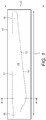
- Figure 1 is a plan view of an elongate female mould 10, which is used to form the windward shell of a wind turbine rotor blade.
- the dashed outline 12 in Figure 1 represents the general shape of the wind turbine blade, with the area inside the dashed line representing the female mould surface 14.
- the mould surface 14 extends in a longitudinal direction L from a root portion 15 to a tip portion 16, and in a chordwise direction C between a leading edge 17 and a trailing edge 18.
- the longitudinal and chordwise directions L, C are mutually perpendicular.
- FIG 2 shows a cross-section of a mould assembly 20 for manufacturing a rotor blade 22 of a wind turbine.
- the mould assembly 20 includes the windward mould 10 of Figure 1 , as viewed in cross-section in the direction of arrows A-A in Figure 1 , and a leeward mould 24.
- the windward mould 10 is supported by a windward frame 25, whilst the leeward mould 24 is supported by a leeward frame 26.
- the frames 25, 26 are each made from steel.
- the mould assembly 10 is shown in a closed configuration in Figure 2 , with the leeward mould 24 and frame 26 being arranged on top of the windward mould 10 and frame 25.
- a windward shell 27 of the blade 22 is moulded in the windward mould 10 and a leeward shell 28 is moulded in the leeward mould 24.
- the blade shells 27, 28 are formed from glass-fibre reinforced composite material (GRP).
- GRP glass-fibre reinforced composite material
- the straight dashed line 30 in Figure 1 which extends between the leading edge 17 of the blade 22 and the trailing edge 18 of the blade 22, is commonly referred to as a 'chord line'.
- the double-headed arrow C in Figure 1 represents the chordwise direction.
- the moulds 10, 24 are each made from composite material and comprise a smooth skin 32, which forms the mould surface 14 (see Figure 2 ).
- the skin 32 is backed by a honeycomb core 33, to which a plurality of air ducts 34-38 are attached.
- the air ducts 34-38 are formed from elongate boxes that extend in the longitudinal direction L (see Figure 1 ), i.e. perpendicular to the plane of Figure 2 .
- each mould 10, 24 includes five air ducts 34-38.
- a first air duct 34 is located at the leading edge 17 of the mould 10
- a second air duct 35 is located at the trailing edge 18 of the mould 10
- third and fourth air ducts 36, 37 are located on either side of a spar structure 40 of the blade 22, and a fifth air duct 38 is positioned approximately midway between the spar structure 40 and the trailing edge 18.
- the leeward mould 24 has a corresponding arrangement of air ducts 34'-38' such that when the mould assembly 20 is closed, as shown in Figure 2 , the air ducts 34-38, 34'-38' of the respective moulds 10, 24 are located substantially opposite one another. Curing the blade shells 27, 28 involves blowing warm air through the ducts 34-38, 34'-38'. The warm air diffuses through the honeycomb cores 33 of the respective moulds 10, 24 and warms the mould skins 32.
- the moulds 10, 24 are coupled to the respective frames 25, 26 via a plurality of interface brackets 44-48, 44'-48'.
- the interface brackets 44-48, 44'-48' are each welded to the frames 25, 26 and bolted to a respective air duct 34-38, 34'-38' of the respective moulds 10, 24.
- a first interface bracket 44 is located at the leading edge 17 and couples the frame 25 to the first air duct 34
- a second interface bracket 45 is located at the trailing edge 18 and couples the frame 25 to the second air duct 35
- three intermediate interface brackets 46, 47, 48 are provided which couple the frame 25 respectively to the third, fourth and fifth air ducts 36, 37, 38.
- a corresponding set of interface brackets 44'-48' is used to couple the leeward frame 26 to the respective air ducts 34-38 of the leeward mould 24.
- the interface brackets 44-48, 44'-48' will now be described in more detail with reference to Figures 3 to 5 .
- an interface bracket 44 generally comprises a first part 50 and a second part 51, which are moveable relative to one another via a slide rod 52 and eye bearing assembly 53, along first and second mutually perpendicular axes as represented by the respective dashed lines 54 and 55.
- the bracket 44 is mounted to the mould 10 and frame 25 (see Figure 2 ) such that the first axis 54 is aligned with the longitudinal direction L (see Figure 1 ) and the second axis 55 is aligned with the chordwise direction C (see Figure 1 ).
- the mechanism for providing this relative movement is described in more detail later, following a discussion of the component parts of the bracket 44.
- the first part 50 of the bracket 44 comprises a box-shaped housing 56, which attaches to the frame 25 of the mould assembly 20 shown in Figure 2 .
- the second part 51 of the bracket 44 comprises a U-shaped mount 57, which has a flat base 58 and a pair of opposed sidewalls 60, 60'.
- the U-shaped mount 57 attaches to an air duct 34 of the mould 10 (see Figure 2 ) via a pair of bolts 61, 61', which extend through respective slots 62, 62' provided in the base 58 of the U-shaped mount 57.
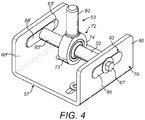
- first and second elongate slots 63, 63' are provided in the respective sidewalls 60, 60' of the U-shaped mount 57.
- the first slot 63 is shorter than the second slot 63'.
- the slide rod 52 extends between the slots 63, 63' in a direction substantially perpendicular to the direction of extension of the slots 63, 63'.
- a first end 65 (see Figure 5A ) of the slide rod 52 includes a first elongate portion 66 (see Figure 3 ) and a second end 65' of the slide rod 52 includes a second identical elongate portion 66'.
- the elongate portions 66, 66' which are referred to hereafter as 'parallel keys', are received in the respective slots 63, 63'.
- the parallel keys 66, 66' are each substantially the same shape and size as the shorter first slot 63. Consequently, the first parallel key 66 is prevented from moving within the first slot 63, whilst the second parallel key 66' is able to slide within the second slot 63' in a direction perpendicular to the direction of extension of the slide rod 52.
- the parallel keys 66, 66' are retained in the slots 63, 63' by a pair of bolts 67, 67' and a pair of washers 68, 68'.
- the bolts 67, 67' are provided axially in the respective ends 65, 65' of the slide rod 52 and the washers 68, 68' are provided between the respective bolts 67, 67' and the respective ends 65, 65' of the slide rod 52 on an outer side 70 of the respective sidewalls 60, 60' of the U-shaped mount 57.
- the washers 68, 68' are suitably larger than the slots 63, 63' to prevent axial movement of the slide rod 52 relative to the U-shaped mount 57 along the first axis 54, thereby serving to retain the parallel keys 66, 66' in the respective slots 63, 63'.
- the first bolt 67 is loosely tightened to allow some 'play' between the first end 65 of the slide rod 52 and the first parallel key 66, i.e. so that the slide rod 52 can pivot relative to the U-shaped mount 57.
- the first part 50 of the bracket 44 includes the eye bearing assembly 53, which includes an eyelet 72 that is slidably coupled to the slide rod 52.
- the eyelet 72 comprises an annular outer portion 73, which surrounds a substantially spherical inner portion 74.
- the spherical inner portion 74 includes a through bore 75 through which the slide rod 52 extends such that the eyelet 72 and slide rod 52 are slidably engaged.
- the eyelet 72 further includes an intermediate portion 76, which is provided between the spherical inner portion 74 and the annular outer portion 73.
- the intermediate portion 76 has a cylindrical outer surface 77 complementary to a cylindrical inner surface 78 of the annular portion 73, and a curved inner surface 79 complementary to a curved outer surface 80 of the spherical inner portion 74.
- the intermediate portion 76 is fixed to the outer annular portion 73 whilst the inner surface 79 of the intermediate portion 76 is configured to slide over the curved surface 80 of the spherical portion 74.
- the eye bearing assembly 53 provides an articulated joint between the first and second parts 50, 51 of the bracket 44 that enables these parts to pivot relative to one another.
- the articulated joint in this example is effectively a ball joint and provides relative movement between the first and second parts 50, 51 in three rotational degrees of freedom.
- the annular outer portion 73 of the eye bearing 53 is provided at one end of a threaded shaft 82, such that the shaft 82 extends substantially perpendicular to the slide rod 52.
- the other end of the shaft 82 is received inside a tubular bushing 83, which is inserted in an aperture 84 in a bottom plate 85 of the housing 56 of the first part 50 of the bracket 44.
- a threaded bolt 86 extends into the box-shaped housing 56 through an aperture 87 provided in a top plate 88 of the housing 56.
- a first end 89 of the bolt 86 is located outside the housing 56 and a second end 90 of the bolt 86 is located inside the housing 56.
- the tubular bushing 83 connects the second end 90 of the bolt 86 coaxially to the threaded shaft 82 of the eye bearing assembly 53.
- the bolt 86 is clamped to the top plate 88 of the housing 56 via a pair of nuts 90, 90' and washers 91, 91' arranged on opposite sides of the top plate 88.
- the first and second parts 50, 51 of the bracket 44 may be adjusted vertically (in the flapwise direction) by loosening the pair of nuts 90, 90' at the top plate 88 and turning both nuts 90, 90' so that the bolt 86 is pushed up or down. This causes the first and second parts 50, 51 of the bracket to move towards or away from one another.
- vertical adjustment may instead be provided by moving both the first and second parts 50, 51 of the bracket together relative to the mould 10 or the frame 25.
- the bolt 89 may be attached to the frame 25, and hence turning both nuts 90, 90' causes both the first and second parts 50, 51 of the bracket to move together to provide a vertical adjustment.
- FIG 6 which is an enlarged view of the part of Figure 2 within the dashed box 92, i.e. showing a leading-edge bracket 44, the U-shaped mount 57 is bolted to the first air duct 34 of the windward mould 10 and the box-shaped housing 56 is welded to the steel windward frame 25.
- the U-shaped mount 57 is arranged such that the elongate slot 63' extends in the chordwise direction C of the mould 10.
- FIG 7 which is a side view of the leading-edge bracket 44 as viewed in the direction of the arrow 94 in Figure 2
- the slide rod 52 which is fixed perpendicular to the slots 63, 63' ( Figure 3 ) extends in the longitudinal direction L.
- the other interface brackets are mounted in the same way, i.e. with their slots 63, 63' extending in the chordwise direction C and their slide rods 52 oriented in the longitudinal direction L.
- Figures 8A and 8B show the interface bracket 44 in a neutral or 'cold' position when the mould 10 is cold, i.e. before heat is applied to the mould 10, whilst Figures 8C and 8D show the position of the interface bracket 44 in a 'hot' position after the mould 10 has been heated.
- the mould 10 and frame 25 are represented schematically in Figures 8A to 8D , and the box-shaped housing 56 has been omitted to simplify these views.
- Figures 8A and 8C are side views of the bracket 44, showing the longitudinal direction L
- Figures 8B and 8D are end views of the bracket 44 as viewed in the direction of the respective arrows 95, 96 in Figures 8A and 8C , and showing the chordwise direction C.
- the eyelet 72 is located towards the first end 65 of the slide rod 52, and hence near the first, relatively short slot 63 of the U-mount 57 (see Figure 4 ).
- the first parallel key 66 is the same size as the first slot 63 and hence the first end 65 of the slide rod 52 is prevented from sliding in the first slot 63 in the chordwise direction.
- the loosely tightened bolt 67 at the first end 65 of the slide rod 52 allows the slide rod to pivot at the first end relative to the U-mount 57.
- the second parallel key 66' at the second end 65' of the slide rod 52 is located in a neutral position in the second slot 63', such that there is approximately 2mm clearance between each end of the parallel key 66' and the slot 63' in the chordwise direction C.
- FIGs 8C and 8D show the expanded mould 10 with the interface bracket 44 in a 'hot' position.
- the U-mount 57 and slide rod 52 move together with the mould 10 in the longitudinal direction L because the U-mount 57 is bolted to the mould 10 and the slide rod 52 is fixed in the longitudinal direction L to the U-mount 57.
- the slide rod 52 slides through the eyelet 72, which is mounted to the frame 25, such that the eyelet 72 ends up being located towards the second end 65' of the slide rod 52, i.e. close to the relatively long second slot 63' in the U-mount 57 ( Figure 8D ).
- the U-mount 57 is free to move in the chordwise direction C relative to the slide rod 52 as the mould 10 expands.
- the extent of relative movement permitted is determined by the clearance between the second parallel key 66' and the relatively long slot 63', which in this example is +/- 2 mm. Movement in the chordwise direction is also facilitated by the ability of the slide rod 52 to pivot at the first end, as described above.
- the mould 10 has expanded by approximately 2 mm in the chordwise direction C such that the slide rod 52 and second parallel key 66' have ended up towards one end of the second slot 63'.
- slots 63, 63' and parallel keys 66, 66' in this embodiment means that relative chordwise sliding between the mould 10 and the frame 25 is restricted in the cold condition and progressively allowed as the mould 10 expands longitudinally.
- the mould 10 is therefore advantageously rigid in the cold condition, yet free to expand in the chordwise direction when heated.
- the various interface brackets 44-48, 44'-48' in this example are configured to permit different amounts of relative chordwise movement between the moulds 10, 24 and the respective frames 25, 26.
- the brackets 44, 44' at the leading edge 17 are configured to allow relative movement of +/- 2 mm in the chordwise direction C
- the brackets 45, 45' at the trailing edge 18 and the intermediate brackets 46-48, 46'-48' are configured to allow relative chordwise movement of +/-10 mm.
- the second slot 63' of the respective trailing edge brackets 45, 45' and intermediate brackets 46-48, 46'-48' is 16 mm longer than the second slot 63' of the respective leading edge brackets 44, 44'.
- only the intermediate and trailing edge brackets may permit chordwise movement, with the leading edge brackets being completely restrained in the chordwise direction.
- the second slots 63' of the various brackets 44-48, 44'-48' may all be the same length, and the second parallel keys 66' of the various brackets 44-48, 44'-48' may have different lengths. This would allow a universal U-mount 57 to be used across all brackets 44-48, 44'-48'. It will be appreciated that the slide rod/parallel key assembly 52, 66, 66' in the present embodiment is universal across the various brackets 44-48, 44'-48'. In other variants of the invention, clearance may be provided between the first slot 63 and the first parallel key 66 such that chordwise movement is permitted in the 'cold' position of the brackets 44-48, 44'-48'.
- the amount of movement permitted in the longitudinal direction L is determined by the length of the slide rod 52 and the dimensions of the eyelet 72.
- the slide rod 52 is approximately 80 mm in length and the permitted lengthwise displacement is 60 mm.
- the mould 10, 24 Since the U-mount 57 is rigidly mounted to the mould 10, 24 with the slots 63, 63' aligned with the chordwise direction C and the slide rod 52 aligned in the longitudinal direction L, the mould 10, 24 is constrained to move only in those two mutually orthogonal directions, which ensures that the geometry of the mould 10, 24 is preserved during thermal expansion.
- any misalignment between the moulds 10, 24 and the respective frames 25, 26 may be compensated for by the articulated joint provided by the eye-bearing assembly 53.
- the articulated joint allows the U-shaped mount 57 of the second part 51 of the bracket to move in three rotational degrees of freedom relative to the box-shaped housing 50 of the second part 50 of the bracket. It will be appreciated that this mechanism is entirely decoupled from the mechanisms for accommodating thermal expansion described above because the articulated joint does not affect the alignment of the slots 63, 63' and slide rod 52 with respect to the mould 10, 24.
- both ends 65, 65' of the rod 52 may be moveable within the respective slots 63, 63'.
- both parallel keys 66, 66' may be suitably shorter than their respective slots 63, 63'.
- the ends 65, 65' of the rod 52 may not include parallel keys 66, 66'.
- the bare ends 65, 65' of the rod 52 may be slidable in the respective slots 63, 63'.
- the slots 63, 63' may alternatively be the same size and different sized keys 66, 66' may be used.
- This arrangement conveniently allows a universal mount 57 to be used for all the interface brackets 44-48, 44'-48'.
- a rod 52 fixed at one end that end need not be received in a slot. Instead the fixed end may be bolted or welded to the mount 57.
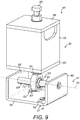
- Figure 9 shows an interface bracket 98 according to a second embodiment of the invention.
- both ends of the slide rod 52 are fixed to the mount 57. Consequently, the bracket 98 accommodates thermal expansion of the mould in the spanwise direction but not in the chordwise direction.
- Other features of the bracket 98 are identical to the bracket described above and so are not repeated.
- the brackets 98 of the second embodiment may be used in combination with the brackets 44 of the first embodiment.
- the brackets 98 may be used at certain positions of the mould assembly where chordwise expansion does not occur or to restrict chordwise expansion at those locations, whilst the brackets 44 of the first embodiment may be used at other positions of the mould assembly to permit chordwise expansion at those locations.
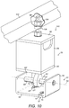
- Figure 10 shows an interface bracket 100 according to a third (not claimed) embodiment of the invention.
- This embodiment is similar to the second embodiment in that it only accommodates thermal expansion in the spanwise direction. However, this embodiment also omits the articulated ball joint of the first and second embodiments. Again, these brackets 100 may be used in combination with the brackets of the first and/or second embodiments.
- Figure 10 also shows the interface bracket 100 mounted to a tubular member 102 of the frame 25, 26 shown in Figure 2 .
- the threaded bolt 86 extends through a hole provided in the tubular member 102 and a pair of nuts 104, 106 are used to clamp the bracket 100 to the tubular member.
- One of the nuts 104 is provide inside the tubular member (as shown in the cutaway view), whilst the other nut 106 is provided outside the tubular member 102.
- the threaded bolt 86 may be turned to vary the extent to which the bolt 86 extends into the tubular member 102.
- this adjustment allows the bracket 100 to accommodate varying clearances between the mould and the frame. Furthermore, once the bracket 100 has been mounted to the mould and the frame, this adjustment can be used to vary the separation between the mould and the frame in the flapwise direction, and hence to adjust the shape of the mould as required. Whilst this flapwise adjustment has been described in relation to the third embodiment of the invention, it will be appreciated that it is equally applicable to the first and second embodiments.
- Figure 11 shows an interface bracket 108 according to a fourth embodiment of the invention.
- the second part 51 of the bracket 108 is generally box-shaped and includes an upstanding flange 110 on a first face 112 for mounting to the mould or frame of the mould assembly.
- the eyelet 72 of the first part 51 (not shown) of the bracket 108 extends through an aperture 114 in an opposed second face 116 of the bracket 108, and is slidably coupled to the slide rod 52 in substantially the same way as the brackets described above.
- a pair of flanges 118 are welded to an outer surface 120 of a first side 122 of the bracket 108, respectively at either end of the slot 63. Whilst not visible in the perspective view of Figure 11 , a similar pair of flanges is welded to the opposed second side 124 of the bracket 108.
- the flanges 118 each include an aperture 126 through which a respective threaded bolt 128 extends parallel to the slot 63 and towards an end 130 of the slide rod 52.
- the end 130 of the slide rod 52 is provided with flat side surfaces 132.
- the bolts 128 extend coaxially on the respective sides of the slide rod 52, and the separation between the respective ends 134 of the bolts 128 delimits the extent of relative chordwise movement permitted by the bracket 108.
- this arrangement provides an alternative to the parallel key arrangement described in relation to the first embodiment.
- the amount of separation between the respective ends 134 of the bolts 128 can be adjusted by turning the bolts 128.
- the bolts 128 are locked in place by nuts 136, which abut the respective flanges.
- the bolts 128 can be used to move the mould relative to the supporting frame in the chordwise direction, and/or actively to adjust the shape of the mould in the chordwise direction. This is achieved by extending the bolts 128 such that the end 130 of the slide rod 52 is clamped between the mutually opposed bolts 128. This is the configuration shown in Figure 11 , whereby the ends 134 of the respective bolts 128 each abut a respective flat side surface 132 of the slide rod 52. In this configuration, tightening one of the bolts 128 and loosening the other bolt 128 can be used to move or otherwise adjust the mould in the chordwise direction.
Landscapes
- Engineering & Computer Science (AREA)
- Mechanical Engineering (AREA)
- Wind Motors (AREA)
- Moulds For Moulding Plastics Or The Like (AREA)
Description
- The present invention relates generally to interface brackets of the type used to couple a wind turbine blade mould to a supporting structure such as a frame, and more specifically to an interface bracket that accommodates thermal expansion of the mould relative to the supporting structure.
- Wind turbine rotor blades extend longitudinally from root to tip in a 'spanwise' direction. The blades have an airfoil profile in cross-section, which comprises longitudinally extending leading and trailing edges. A 'chordwise' direction of the blade is defined as a direction perpendicular to the spanwise direction, and which lies in a plane containing the leading and trailing edges. A 'flapwise' direction of the blade is the direction perpendicular to both the spanwise and chordwise directions.
- Wind turbine rotor blades are generally formed from two shells, a windward shell and a leeward shell, which are joined together to form the complete blade. Each shell is moulded from composite materials in a respective female mould having a shape corresponding to the shape of the shell to be produced. The terms 'spanwise', 'chordwise' and 'flapwise' defined above with respect to the blade are also used hereinafter to refer to the corresponding directions with respect to the moulds. The moulds themselves are made from composite materials and are supported by respective steel frames. Interface brackets are used to connect the mould to the respective frames.
- Manufacturing the blades involves laying up composite material in the respective female moulds. Once the material has been laid up in the respective moulds, the moulds are placed one on top of the other and heat and pressure is applied to the closed mould assembly to cure the composite shells. During the cure cycle, the applied heat causes the blade shells and the moulds to expand relative to the steel frames. The blade shells and the moulds have a similar coefficient of thermal expansion because they are both made from similar composite material. Consequently, the shells expand at a similar rate to the moulds. However, the shells and moulds have a significantly different thermal expansion coefficient to the steel frames, causing the shells and moulds to expand more than the steel frames.
- In order to avoid distortion of a mould during a cure cycle, it is known to use interface brackets that accommodate relative movement between the mould and the supporting structure, which is caused by these differential rates of thermal expansion. Background art is discussed briefly below.
-
WO2011/029273A1 describes an interface device for adjusting the shape of a rotor blade mould in the chordwise direction. The device is configured to accommodate thermal expansion of the mould relative to a frame in the spanwise direction. The chordwise shape adjustment prevents the device from accommodating thermal expansion in the chordwise direction. -
US 4,398,693 describes a device for fastening a rotor blade mould to a supporting structure. The device is configured to accommodate thermal expansion of the mould relative to the supporting structure in both spanwise and chordwise directions. -
WO2006070013A1 describes interface brackets for coupling a mould to a supporting structure. A plurality of brackets are arranged radially with respect to an expansion centre to accommodate spanwise and chordwise expansion of the mould relative to the supporting structure. -
WO2010/103493 discloses a wind turbine blade mould in which parallel (i.e. chordwise) mould deformations can be corrected by means of shape adjustment devices. Spanwise tubular stiffening ribs are bonded to the mould shell. The shape adjustment devices in the form of threaded, adjustable supports connect the stiffening ribs with a mould frame and are adjustable to push or pull the mould back into shape. - Utility model
CN200920267467 - It is important that the mould is precisely aligned with the supporting structure in order for the interface brackets successfully to accommodate relative movement between the mould and the supporting structure. In practice, hundreds of interface brackets may be required for a wind turbine blade mould, as the blades of modern utility-scale wind turbines are very large, typically in excess of sixty metres in length. Achieving such precise alignment at each bracket is challenging and time consuming.
- Against this background, the present invention aims to provide an improved interface bracket.
- According to the present invention there is provided a bracket for clamping a wind turbine blade mould to a supporting structure, the bracket comprising a first part and a second part for attaching to the mould and to the supporting structure, respectively, or vice versa. the first and second parts being connected together and configured to provide constrained relative movement along a first axis to accommodate thermal expansion of the mould relative to the supporting structure in a first direction parallel to the first axis; wherein the first and second parts of the bracket are connected via an articulated joint that allows the first and second parts to pivot relative to one another without moving the first axis, such that the bracket can independently accommodate misalignments between the mould and the supporting structure; wherein the first and second parts are configured to slide relative to one another in the first direction; wherein the bracket further includes a slide rod extending along the first axis, the slide rod being fixed relative to the second part of the bracket in the first direction, and the first part of the bracket includes an eyelet that is slidably engaged with the slide rod to permit relative movement between the first and second parts of the bracket in the first direction; wherein the eyelet is configured to pivot relative to the slide rod; and wherein the articulated joint is a ball joint configured to provide relative movement between the first and second parts in three degrees of freedom.
- The bracket of the present invention accommodates thermal expansion of a mould relative to a supporting structure and is also able to compensate for misalignments between the mould and the supporting structure.
- The bracket is able to accommodate differential rates of thermal expansion between the mould and the supporting structure by virtue of the first and second parts that are able to move relative to one another. The first and second parts are constrained to move along the first axis, which prevents distortion of the mould during thermal expansion.
- The articulated joint allows the bracket to compensate for misalignments between the mould and the supporting structure, which makes the bracket relatively easy to install. The articulated joint allows the first and second parts of the bracket to move relative to one another without changing the direction of the first axis of relative movement. In other words, the mechanism for compensating for misalignments is decoupled from the mechanism for compensating for thermal expansion.
- The first and second parts of the bracket are configured to slide relative to one another in the first direction. The bracket includes a slide rod extending along the first axis. The slide rod is fixed relative to the second part of the bracket in the first direction. The first part of the bracket includes an eyelet that is slidably engaged with the slide rod to permit relative movement between the first and second parts of the bracket in the first direction.
- The eyelet is configured to pivot relative to the slide rod. The eyelet may include an outer part and an inner part, the inner part being slidably engaged with the slide rod and the outer part being configured to pivot with respect to the inner part. The inner and outer parts together may define the articulated joint. The inner part may be substantially spherical (i.e. spherical or at least partly spherical) such that the inner and outer parts effectively form a ball joint.
- In certain embodiments of the present invention, the first and second parts of the bracket are further configured to provide constrained relative movement along a second axis transverse to the first axis to accommodate thermal expansion of the mould relative to the supporting structure in a second direction parallel to the second axis. In such embodiments, the articulated joint is preferably configured to allow the first and second parts of the bracket to pivot relative to one another without moving the mutually transverse first and second axes.
- Preferably the slide rod is permitted to move freely relative to the second part of the bracket in the second direction to permit relative movement between the first and second parts of the bracket in the second direction. To this end, the second part of the bracket may include an elongate slot extending in the second direction in which a first end of the slide rod is slidably received. A second end of the slide rod may be fixed relative to the second part of the bracket in the second direction. This arrangement may substantially prevent relative movement in the second direction when the eyelet is located towards the second end of the rod. In other embodiments, both ends of the slide rod may be slidably received in respective opposed slots.
- An elongate member, also referred to herein as a 'parallel key' may be provided at one or both ends of the rod. The or each elongate member may be received in a respective slot. The extent of relative movement permitted between the first and second parts of the bracket in the second direction is determined by the amount of clearance in the second direction between the or each elongate member and the respective slot. Relative movement in the second direction is facilitated by having an elongate member that is shorter than its respective slot. Conversely, the rod may be fixed at one end by having an elongate member at that end which is the same length as its respective slot. Of course, for embodiments in which the rod is fixed at one end, the fixed end may not include an elongate member and may instead be bolted, welded or otherwise fixed to the second part of the bracket.
- For embodiments having an elongate member at both ends of the rod, the elongate members may be substantially the same length and the slots may have different lengths. For example one slot may be the same length as the elongate members and the other slot may be longer such the rod is fixed at one end whilst the other end of the rod is moveable in the second direction. Alternatively the elongate members may have different lengths and the slots may have substantially the same length. For example, one elongate member may be the same length as the slots and the other elongate member may be shorter so that the rod is fixed at one end and slidable in the respective slot at the other end. In other embodiments, both elongate members may be slidable in the respective slots.
- The second part of the bracket may comprise a U-shaped mount. The U-shaped mount may have a substantially flat base and a pair of opposed sidewalls. The or each slot may be provided in a respective sidewall of the U-shaped mount.
- The bracket is preferably adjustable in a third direction perpendicular to the mutually transverse first and second axes. This adjustment may vary the separation between the first and second parts in the third direction. Alternatively the adjustment may cause the first and second parts to move together in the third direction relative to the mould and supporting structure.
- The mutually transverse first and second axes are preferably mutually perpendicular. In preferred examples of the invention, the mould is a mould for part of a wind turbine blade, for example a blade shell. The first and second axes are preferably substantially parallel to the spanwise and chordwise directions of the mould respectively. The third direction is preferably substantially parallel to the flapwise direction of the mould.
- According to the present invention, there is also provided a mould assembly comprising a mould coupled to a supporting structure by a plurality of brackets as described above.
- As mentioned above, the mould is preferably for moulding part of a wind turbine rotor blade, for example the blade shell. The brackets are preferably arranged to accommodate thermal expansion of the mould relative to the supporting structure in mutually perpendicular spanwise and chordwise directions of the mould.
- A first set of brackets may be arranged respectively at intervals along a leading edge of the mould. A second set of brackets may be arranged respectively at intervals along a trailing edge of the mould. The first and second sets of brackets may be configured to accommodate different extents of thermal expansion of the mould in the chordwise direction. Preferably the brackets at the trailing edge are configured to accommodate greater chordwise thermal expansion than the brackets at the leading edge.
- The mould may include a plurality of air ducts through which warm air is channelled to heat the moulds. The respective brackets are preferably attached to these air ducts.
- The inventive concept includes a wind turbine blade mould assembly comprising a mould coupled to a supporting structure by a plurality of brackets as described above.
- According to a second aspect of the present invention (not claimed) there is provided a bracket for clamping a wind turbine blade mould to a supporting structure, the bracket comprising a first part and a second part for attaching to the mould and the supporting structure, respectively, or vice versa, the first and second parts being connected together and configured to provide constrained relative movement between the mould and the supporting structure to accommodate thermal expansion of the mould relative to the supporting structure in a spanwise direction and/or in a chordwise direction; wherein the bracket is adjustable in a generally flapwise direction substantially perpendicular to both the spanwise and chordwise directions to vary the separation between the mould and the supporting structure in the flapwise direction.
- Once the brackets are clamped between the mould and the supporting structure, the flapwise adjustment enables the brackets to be used to change the shape of the mould slightly.
- As described above, the first and second parts of the bracket may be connected via an articulated joint that allows the first and second parts to pivot relative to one another, such that the bracket can independently accommodate misalignments between the mould and the supporting structure.
- The bracket of the invention is defined in appended
claim 1. Further optional features are defined in appended subclaims 2-12. A mould assembly according to the invention is defined in appended claim 13. Optional features thereof are defined in appended subclaims 14 and 15. Optional features described above and/or claimed in respect to the bracket of the first aspect of the present invention are equally applicable to the bracket of the second aspect of the invention but are not repeated herein in order to avoid repetition. - In order that the present invention may be more readily understood, embodiments of the invention will now be described in detail, by way of example only, with reference to the following figures, in which:
-
Figure 1 is a plan view of a windward mould for a windward shell of a wind turbine blade, with the arrows L and C respectively indicating longitudinal and chordwise directions of the mould; -
Figure 2 is a cross-section through the windward mould taken along the line A-A inFigure 1 , in which a leeward mould is arranged on top of the windward mould, with each mould being coupled to a respective supporting frame by a plurality of interface brackets; -
Figure 3 is a perspective view of an interface bracket according to a first embodiment of the present invention; -
Figure 4 is an enlarged perspective view of a lower part of the interface bracket ofFigure 3 ; -
Figure 5A is a cross-sectional view of the interface bracket ofFigure 3 ; -
Figure 5B is an enlarged view of the part of the interface bracket within the dashed box ofFigure 5A ; -
Figure 6 is an enlarged view of the part ofFigure 2 within the dashed box, i.e. showing an interface bracket located at a leading edge of the windward mould; -
Figure 7 is a side view of the bracket shown inFigure 6 , as viewed in the direction of thearrow 94 inFigure 2 ; -
Figures 8A-8D illustrate schematically how the interface brackets accommodate relative movement between the mould and the frame when the mould is heated, wherein:-
Figure 8A is a side view of an interface bracket in a neutral position before the mould is heated; -
Figure 8B is an end view of the interface bracket in the neutral position, as viewed in the direction ofarrow 95 inFigure 8A ; -
Figure 8C is a side view of the interface bracket after the mould has been heated, in which the interface bracket has accommodated longitudinal expansion of the mould relative to the frame; and -
Figure 8D is an end view of the interface bracket after the mould has been heated, as viewed in the direction ofarrow 96 inFigure 8C , in which the interface bracket has accommodated chordwise expansion of the mould relative to the frame;
-
-
Figure 9 is a perspective view of an interface bracket according to a second embodiment of the present invention; -
Figure 10 shows an interface bracket according to a third embodiment (not claimed) of the present invention; and -
Figure 11 shows an interface bracket according to a fourth embodiment of the present invention. -
Figure 1 is a plan view of an elongatefemale mould 10, which is used to form the windward shell of a wind turbine rotor blade. The dashedoutline 12 inFigure 1 represents the general shape of the wind turbine blade, with the area inside the dashed line representing thefemale mould surface 14. Themould surface 14 extends in a longitudinal direction L from aroot portion 15 to atip portion 16, and in a chordwise direction C between aleading edge 17 and a trailingedge 18. The longitudinal and chordwise directions L, C are mutually perpendicular. -
Figure 2 shows a cross-section of amould assembly 20 for manufacturing arotor blade 22 of a wind turbine. Themould assembly 20 includes thewindward mould 10 ofFigure 1 , as viewed in cross-section in the direction of arrows A-A inFigure 1 , and a leeward mould 24. Thewindward mould 10 is supported by awindward frame 25, whilst the leeward mould 24 is supported by aleeward frame 26. Theframes mould assembly 10 is shown in a closed configuration inFigure 2 , with the leeward mould 24 andframe 26 being arranged on top of thewindward mould 10 andframe 25. - A
windward shell 27 of theblade 22 is moulded in thewindward mould 10 and aleeward shell 28 is moulded in the leeward mould 24. Theblade shells line 30 inFigure 1 , which extends between theleading edge 17 of theblade 22 and the trailingedge 18 of theblade 22, is commonly referred to as a 'chord line'. The double-headed arrow C inFigure 1 represents the chordwise direction. - The
moulds 10, 24 are each made from composite material and comprise asmooth skin 32, which forms the mould surface 14 (seeFigure 2 ). Theskin 32 is backed by ahoneycomb core 33, to which a plurality of air ducts 34-38 are attached. The air ducts 34-38 are formed from elongate boxes that extend in the longitudinal direction L (seeFigure 1 ), i.e. perpendicular to the plane ofFigure 2 . - As shown in
Figure 2 , eachmould 10, 24 includes five air ducts 34-38. Considering just thewindward mould 10, afirst air duct 34 is located at theleading edge 17 of themould 10, asecond air duct 35 is located at the trailingedge 18 of themould 10, third andfourth air ducts spar structure 40 of theblade 22, and afifth air duct 38 is positioned approximately midway between thespar structure 40 and the trailingedge 18. - The leeward mould 24 has a corresponding arrangement of air ducts 34'-38' such that when the
mould assembly 20 is closed, as shown inFigure 2 , the air ducts 34-38, 34'-38' of therespective moulds 10, 24 are located substantially opposite one another. Curing theblade shells honeycomb cores 33 of therespective moulds 10, 24 and warms the mould skins 32. - The
moulds 10, 24 are coupled to therespective frames frames respective moulds 10, 24. Considering just thewindward mould 10 and thewindward frame 25, afirst interface bracket 44 is located at theleading edge 17 and couples theframe 25 to thefirst air duct 34; asecond interface bracket 45 is located at the trailingedge 18 and couples theframe 25 to thesecond air duct 35; and threeintermediate interface brackets frame 25 respectively to the third, fourth andfifth air ducts leeward frame 26 to the respective air ducts 34-38 of the leeward mould 24. The interface brackets 44-48, 44'-48' will now be described in more detail with reference toFigures 3 to 5 . - Referring to the perspective view of
Figure 3 , aninterface bracket 44 according a first embodiment of the present invention generally comprises afirst part 50 and asecond part 51, which are moveable relative to one another via aslide rod 52 andeye bearing assembly 53, along first and second mutually perpendicular axes as represented by the respective dashedlines bracket 44 is mounted to themould 10 and frame 25 (seeFigure 2 ) such that thefirst axis 54 is aligned with the longitudinal direction L (seeFigure 1 ) and thesecond axis 55 is aligned with the chordwise direction C (seeFigure 1 ). The mechanism for providing this relative movement is described in more detail later, following a discussion of the component parts of thebracket 44. - The
first part 50 of thebracket 44 comprises a box-shapedhousing 56, which attaches to theframe 25 of themould assembly 20 shown inFigure 2 . Thesecond part 51 of thebracket 44 comprises aU-shaped mount 57, which has aflat base 58 and a pair ofopposed sidewalls 60, 60'. TheU-shaped mount 57 attaches to anair duct 34 of the mould 10 (seeFigure 2 ) via a pair ofbolts 61, 61', which extend throughrespective slots 62, 62' provided in thebase 58 of theU-shaped mount 57. - As best seen in
Figure 4 , first and secondelongate slots 63, 63' are provided in therespective sidewalls 60, 60' of theU-shaped mount 57. thefirst slot 63 is shorter than the second slot 63'. Theslide rod 52 extends between theslots 63, 63' in a direction substantially perpendicular to the direction of extension of theslots 63, 63'. A first end 65 (seeFigure 5A ) of theslide rod 52 includes a first elongate portion 66 (seeFigure 3 ) and a second end 65' of theslide rod 52 includes a second identical elongate portion 66'. Theelongate portions 66, 66', which are referred to hereafter as 'parallel keys', are received in therespective slots 63, 63'. Theparallel keys 66, 66' are each substantially the same shape and size as the shorterfirst slot 63. Consequently, the firstparallel key 66 is prevented from moving within thefirst slot 63, whilst the second parallel key 66' is able to slide within the second slot 63' in a direction perpendicular to the direction of extension of theslide rod 52. - As best seen in
Figure 5A , theparallel keys 66, 66' are retained in theslots 63, 63' by a pair ofbolts 67, 67' and a pair ofwashers 68, 68'. Thebolts 67, 67' are provided axially in the respective ends 65, 65' of theslide rod 52 and thewashers 68, 68' are provided between therespective bolts 67, 67' and the respective ends 65, 65' of theslide rod 52 on anouter side 70 of therespective sidewalls 60, 60' of theU-shaped mount 57. Referring toFigure 3 , thewashers 68, 68' are suitably larger than theslots 63, 63' to prevent axial movement of theslide rod 52 relative to theU-shaped mount 57 along thefirst axis 54, thereby serving to retain theparallel keys 66, 66' in therespective slots 63, 63'. Thefirst bolt 67 is loosely tightened to allow some 'play' between thefirst end 65 of theslide rod 52 and the firstparallel key 66, i.e. so that theslide rod 52 can pivot relative to theU-shaped mount 57. - The
first part 50 of thebracket 44 includes theeye bearing assembly 53, which includes aneyelet 72 that is slidably coupled to theslide rod 52. Referring toFigures 4 and5A , theeyelet 72 comprises an annularouter portion 73, which surrounds a substantially sphericalinner portion 74. The sphericalinner portion 74 includes a through bore 75 through which theslide rod 52 extends such that theeyelet 72 andslide rod 52 are slidably engaged. - As seen best in the enlarged cross-sectional view of
Figure 5B , theeyelet 72 further includes anintermediate portion 76, which is provided between the sphericalinner portion 74 and the annularouter portion 73. Theintermediate portion 76 has a cylindricalouter surface 77 complementary to a cylindricalinner surface 78 of theannular portion 73, and a curvedinner surface 79 complementary to a curvedouter surface 80 of the sphericalinner portion 74. Theintermediate portion 76 is fixed to the outerannular portion 73 whilst theinner surface 79 of theintermediate portion 76 is configured to slide over thecurved surface 80 of thespherical portion 74. - The
eye bearing assembly 53 provides an articulated joint between the first andsecond parts bracket 44 that enables these parts to pivot relative to one another. The articulated joint in this example is effectively a ball joint and provides relative movement between the first andsecond parts - Referring to
Figure 5A , the annularouter portion 73 of the eye bearing 53 is provided at one end of a threadedshaft 82, such that theshaft 82 extends substantially perpendicular to theslide rod 52. The other end of theshaft 82 is received inside atubular bushing 83, which is inserted in anaperture 84 in abottom plate 85 of thehousing 56 of thefirst part 50 of thebracket 44. A threadedbolt 86 extends into the box-shapedhousing 56 through anaperture 87 provided in atop plate 88 of thehousing 56. Afirst end 89 of thebolt 86 is located outside thehousing 56 and asecond end 90 of thebolt 86 is located inside thehousing 56. Thetubular bushing 83 connects thesecond end 90 of thebolt 86 coaxially to the threadedshaft 82 of theeye bearing assembly 53. - The
bolt 86 is clamped to thetop plate 88 of thehousing 56 via a pair ofnuts 90, 90' andwashers 91, 91' arranged on opposite sides of thetop plate 88. Once theinterface bracket 44 has been mounted to themould 10 and to the frame 25 (Figure 2 ), the first andsecond parts bracket 44 may be adjusted vertically (in the flapwise direction) by loosening the pair ofnuts 90, 90' at thetop plate 88 and turning bothnuts 90, 90' so that thebolt 86 is pushed up or down. This causes the first andsecond parts - In an alternative embodiment (not shown) vertical adjustment may instead be provided by moving both the first and
second parts mould 10 or theframe 25. For example, rather than fixing thehousing 56 to theframe 25, thebolt 89 may be attached to theframe 25, and hence turning bothnuts 90, 90' causes both the first andsecond parts - Referring to
Figure 6 , which is an enlarged view of the part ofFigure 2 within the dashedbox 92, i.e. showing a leading-edge bracket 44, theU-shaped mount 57 is bolted to thefirst air duct 34 of thewindward mould 10 and the box-shapedhousing 56 is welded to thesteel windward frame 25. TheU-shaped mount 57 is arranged such that the elongate slot 63' extends in the chordwise direction C of themould 10. - Referring to
Figure 7 , which is a side view of the leading-edge bracket 44 as viewed in the direction of thearrow 94 inFigure 2 , theslide rod 52, which is fixed perpendicular to theslots 63, 63' (Figure 3 ), extends in the longitudinal direction L. The other interface brackets are mounted in the same way, i.e. with theirslots 63, 63' extending in the chordwise direction C and theirslide rods 52 oriented in the longitudinal direction L. - As mentioned previously, warm air is blown through the air ducts 34-38, 34'-38' of the
moulds 10, 24 to cure theblade shells 27, 28 (seeFigure 2 ). The warm air causes both themoulds 10, 24 and theframes moulds 10, 24 and theframes moulds 10, 24 expand significantly more than theframes moulds 10, 24 to move slightly relative to the steel frames 25, 26 in order to accommodate this differential thermal expansion and hence to prevent themoulds 10, 24 from distorting, as will now be explained with reference toFigures 8A to 8D . -
Figures 8A and 8B show theinterface bracket 44 in a neutral or 'cold' position when themould 10 is cold, i.e. before heat is applied to themould 10, whilstFigures 8C and 8D show the position of theinterface bracket 44 in a 'hot' position after themould 10 has been heated. Themould 10 andframe 25 are represented schematically inFigures 8A to 8D , and the box-shapedhousing 56 has been omitted to simplify these views.Figures 8A and8C are side views of thebracket 44, showing the longitudinal direction L, whilstFigures 8B and8D are end views of thebracket 44 as viewed in the direction of therespective arrows Figures 8A and8C , and showing the chordwise direction C. - Referring first to the side view of
Figure 8A , in the neutral position theeyelet 72 is located towards thefirst end 65 of theslide rod 52, and hence near the first, relativelyshort slot 63 of the U-mount 57 (seeFigure 4 ). As described above, the firstparallel key 66 is the same size as thefirst slot 63 and hence thefirst end 65 of theslide rod 52 is prevented from sliding in thefirst slot 63 in the chordwise direction. However, as mentioned above, the loosely tightenedbolt 67 at thefirst end 65 of theslide rod 52 allows the slide rod to pivot at the first end relative to the U-mount 57. - Referring to the end view of
Figure 8B , the second parallel key 66' at the second end 65' of theslide rod 52 is located in a neutral position in the second slot 63', such that there is approximately 2mm clearance between each end of the parallel key 66' and the slot 63' in the chordwise direction C. - Once heat is applied to the
mould 10, themould 10 expands relative to theframe 25.Figures 8C and 8D show the expandedmould 10 with theinterface bracket 44 in a 'hot' position. Referring toFigure 8C , as themould 10 expands, the U-mount 57 andslide rod 52 move together with themould 10 in the longitudinal direction L because the U-mount 57 is bolted to themould 10 and theslide rod 52 is fixed in the longitudinal direction L to the U-mount 57. Theslide rod 52 slides through theeyelet 72, which is mounted to theframe 25, such that theeyelet 72 ends up being located towards the second end 65' of theslide rod 52, i.e. close to the relatively long second slot 63' in the U-mount 57 (Figure 8D ). - Referring to
Figure 8D , by virtue of theslots 63, 63', the U-mount 57 is free to move in the chordwise direction C relative to theslide rod 52 as themould 10 expands. The extent of relative movement permitted is determined by the clearance between the second parallel key 66' and the relatively long slot 63', which in this example is +/- 2 mm. Movement in the chordwise direction is also facilitated by the ability of theslide rod 52 to pivot at the first end, as described above. As shown inFigure 8D , themould 10 has expanded by approximately 2 mm in the chordwise direction C such that theslide rod 52 and second parallel key 66' have ended up towards one end of the second slot 63'. - The configuration of
slots 63, 63' andparallel keys 66, 66' in this embodiment means that relative chordwise sliding between themould 10 and theframe 25 is restricted in the cold condition and progressively allowed as themould 10 expands longitudinally. Themould 10 is therefore advantageously rigid in the cold condition, yet free to expand in the chordwise direction when heated. - Referring again to
Figure 2 , the various interface brackets 44-48, 44'-48' in this example are configured to permit different amounts of relative chordwise movement between themoulds 10, 24 and therespective frames brackets 44, 44' at theleading edge 17 are configured to allow relative movement of +/- 2 mm in the chordwise direction C, whilst thebrackets 45, 45' at the trailingedge 18 and the intermediate brackets 46-48, 46'-48' are configured to allow relative chordwise movement of +/-10 mm. To this end, the second slot 63' of the respectivetrailing edge brackets 45, 45' and intermediate brackets 46-48, 46'-48' is 16 mm longer than the second slot 63' of the respectiveleading edge brackets 44, 44'. In other embodiments, only the intermediate and trailing edge brackets may permit chordwise movement, with the leading edge brackets being completely restrained in the chordwise direction. - In other embodiments of the invention, the second slots 63' of the various brackets 44-48, 44'-48' may all be the same length, and the second parallel keys 66' of the various brackets 44-48, 44'-48' may have different lengths. This would allow a universal U-mount 57 to be used across all brackets 44-48, 44'-48'. It will be appreciated that the slide rod/parallel
key assembly first slot 63 and the firstparallel key 66 such that chordwise movement is permitted in the 'cold' position of the brackets 44-48, 44'-48'. - It will be apparent that the amount of movement permitted in the longitudinal direction L is determined by the length of the
slide rod 52 and the dimensions of theeyelet 72. In this example theslide rod 52 is approximately 80 mm in length and the permitted lengthwise displacement is 60 mm. - Since the U-mount 57 is rigidly mounted to the
mould 10, 24 with theslots 63, 63' aligned with the chordwise direction C and theslide rod 52 aligned in the longitudinal direction L, themould 10, 24 is constrained to move only in those two mutually orthogonal directions, which ensures that the geometry of themould 10, 24 is preserved during thermal expansion. - It will be appreciated that the accommodation of longitudinal expansion is decoupled from the accommodation of chordwise expansion. Different amounts of longitudinal expansion can be accommodated by varying the length of the
slide rod 52, whilst different amounts of chordwise expansion can be accommodated by varying the relative sizes of theslots 63, 63' andparallel keys 66, 66' for example. The design of the interface brackets 44-48, 44'-48' allows these parameters to be optimised independently. - Any misalignment between the
moulds 10, 24 and therespective frames assembly 53. The articulated joint allows theU-shaped mount 57 of thesecond part 51 of the bracket to move in three rotational degrees of freedom relative to the box-shapedhousing 50 of thesecond part 50 of the bracket. It will be appreciated that this mechanism is entirely decoupled from the mechanisms for accommodating thermal expansion described above because the articulated joint does not affect the alignment of theslots 63, 63' andslide rod 52 with respect to themould 10, 24. - In practice, several hundred interface brackets are used to coupled the
moulds 10, 24 to therespective frames moulds 10, 24 and theframes - Alternative embodiments of the invention are envisaged in which both ends 65, 65' of the
rod 52 may be moveable within therespective slots 63, 63'. In this respect, bothparallel keys 66, 66' may be suitably shorter than theirrespective slots 63, 63'. In other examples, the ends 65, 65' of therod 52 may not includeparallel keys 66, 66'. For example, the bare ends 65, 65' of therod 52 may be slidable in therespective slots 63, 63'. Rather than havingslots 63, 63' of different sizes, theslots 63, 63' may alternatively be the same size and differentsized keys 66, 66' may be used. This arrangement conveniently allows auniversal mount 57 to be used for all the interface brackets 44-48, 44'-48'. For embodiments having arod 52 fixed at one end, that end need not be received in a slot. Instead the fixed end may be bolted or welded to themount 57. -
Figure 9 shows aninterface bracket 98 according to a second embodiment of the invention. In this embodiment, both ends of theslide rod 52 are fixed to themount 57. Consequently, thebracket 98 accommodates thermal expansion of the mould in the spanwise direction but not in the chordwise direction. Other features of thebracket 98 are identical to the bracket described above and so are not repeated. In practice thebrackets 98 of the second embodiment may be used in combination with thebrackets 44 of the first embodiment. For example, thebrackets 98 may be used at certain positions of the mould assembly where chordwise expansion does not occur or to restrict chordwise expansion at those locations, whilst thebrackets 44 of the first embodiment may be used at other positions of the mould assembly to permit chordwise expansion at those locations. -
Figure 10 shows aninterface bracket 100 according to a third (not claimed) embodiment of the invention. This embodiment is similar to the second embodiment in that it only accommodates thermal expansion in the spanwise direction. However, this embodiment also omits the articulated ball joint of the first and second embodiments. Again, thesebrackets 100 may be used in combination with the brackets of the first and/or second embodiments. -
Figure 10 also shows theinterface bracket 100 mounted to atubular member 102 of theframe Figure 2 . The threadedbolt 86 extends through a hole provided in thetubular member 102 and a pair ofnuts bracket 100 to the tubular member. One of thenuts 104 is provide inside the tubular member (as shown in the cutaway view), whilst theother nut 106 is provided outside thetubular member 102. The threadedbolt 86 may be turned to vary the extent to which thebolt 86 extends into thetubular member 102. - When fitting the
bracket 100 to the mould and to the frame, this adjustment allows thebracket 100 to accommodate varying clearances between the mould and the frame. Furthermore, once thebracket 100 has been mounted to the mould and the frame, this adjustment can be used to vary the separation between the mould and the frame in the flapwise direction, and hence to adjust the shape of the mould as required. Whilst this flapwise adjustment has been described in relation to the third embodiment of the invention, it will be appreciated that it is equally applicable to the first and second embodiments. -
Figure 11 shows aninterface bracket 108 according to a fourth embodiment of the invention. In this embodiment, thesecond part 51 of thebracket 108 is generally box-shaped and includes anupstanding flange 110 on afirst face 112 for mounting to the mould or frame of the mould assembly. Theeyelet 72 of the first part 51 (not shown) of thebracket 108 extends through anaperture 114 in an opposedsecond face 116 of thebracket 108, and is slidably coupled to theslide rod 52 in substantially the same way as the brackets described above. - A pair of
flanges 118 are welded to anouter surface 120 of afirst side 122 of thebracket 108, respectively at either end of theslot 63. Whilst not visible in the perspective view ofFigure 11 , a similar pair of flanges is welded to the opposedsecond side 124 of thebracket 108. Theflanges 118 each include anaperture 126 through which a respective threadedbolt 128 extends parallel to theslot 63 and towards anend 130 of theslide rod 52. Theend 130 of theslide rod 52 is provided with flat side surfaces 132. Thebolts 128 extend coaxially on the respective sides of theslide rod 52, and the separation between the respective ends 134 of thebolts 128 delimits the extent of relative chordwise movement permitted by thebracket 108. It will be appreciated that this arrangement provides an alternative to the parallel key arrangement described in relation to the first embodiment. The amount of separation between the respective ends 134 of thebolts 128 can be adjusted by turning thebolts 128. Thebolts 128 are locked in place bynuts 136, which abut the respective flanges. - As an alternative to delimiting the extent of relative chordwise movement, the
bolts 128 can be used to move the mould relative to the supporting frame in the chordwise direction, and/or actively to adjust the shape of the mould in the chordwise direction. This is achieved by extending thebolts 128 such that theend 130 of theslide rod 52 is clamped between the mutually opposedbolts 128. This is the configuration shown inFigure 11 , whereby theends 134 of therespective bolts 128 each abut a respectiveflat side surface 132 of theslide rod 52. In this configuration, tightening one of thebolts 128 and loosening theother bolt 128 can be used to move or otherwise adjust the mould in the chordwise direction. - Many other modifications may be made to the examples described above without departing from the scope of the invention as defined by the accompanying claims.
Claims (15)
- A bracket (44-48, 44'-48', 98, 108) for clamping a wind turbine blade mould (10, 24) to a supporting structure (25, 26), the bracket comprising a first part (50) and a second part (51) for attaching to the mould and the supporting structure, respectively, or vice versa,
the first and second parts being connected together and configured to provide constrained relative movement along a first axis (54) to accommodate thermal expansion of the mould relative to the supporting structure in a first direction parallel to the first axis;
wherein the first and second parts of the bracket are connected via an articulated joint that allows the first and second parts to pivot relative to one another without moving the first axis, such that the bracket can independently accommodate misalignments between the mould and the supporting structure;
wherein the first and second parts are configured to slide relative to one another in the first direction;
wherein the bracket further includes a slide rod (52) extending along the first axis, the slide rod being fixed relative to the second part of the bracket in the first direction, and the first part of the bracket includes an eyelet (72) that is slidably engaged with the slide rod to permit relative movement between the first and second parts of the bracket in the first direction;
wherein the eyelet is configured to pivot relative to the slide rod;
and wherein the articulated joint is a ball joint configured to provide relative movement between the first and second parts in three degrees of freedom. - The bracket of Claim 1, wherein the eyelet includes an outer part (73) and an inner part (74), the inner part being slidably engaged with the slide rod and the outer part being configured to pivot with respect to the inner part.
- The bracket of Claim 2, wherein the inner and outer parts together define the articulated joint.
- The bracket of Claim 3, wherein the inner part is substantially spherical such that the inner and outer parts form said ball joint.
- The bracket of any preceding claim, wherein the first and second parts of the bracket are further configured to provide constrained relative movement along a second axis (55) transverse to the first axis (54) to accommodate thermal expansion of the mould relative to the supporting structure in a second direction parallel to the second axis.
- The bracket of Claim 5, wherein the articulated joint is configured to allow the first and second parts of the bracket to pivot relative to one another without moving the second axis.
- The bracket of Claim 5 or Claim 6, wherein the slide rod is permitted to move freely relative to the second part of the bracket in the second direction to permit relative movement between the first and second parts of the bracket in the second direction.
- The bracket of Claim 7, wherein the second part of the bracket includes an elongate slot (62, 62', 63, 63') extending in the second direction in which a first end of the slide rod is slidably received.
- The bracket of Claim 7, wherein the second part of the bracket includes a pair of opposed elongate slots (62, 62', 63, 63') in which first and second ends of the slide rod are respectively received, the elongate slots each extending in the second direction.
- The bracket of Claim 8 or 9, wherein the second part of the bracket comprises a U-shaped mount (57) having a substantially flat base (58) and a pair of opposed sidewalls (60, 60'), and wherein the or each slot is provided in a respective sidewall of the U-shaped mount.
- The bracket of any of Claims 5 to 10, wherein the first and second axes are mutually perpendicular.
- The bracket of claim 11, wherein said first and second axes are substantially parallel to the spanwise (L) and chordwise (C) directions of the mould respectively.
- A mould assembly (20) comprising a mould (10, 24) coupled to a supporting structure (25, 26) by a plurality of brackets (44-48, 44'-48', 98, 108) as defined in any preceding claim.
- The mould assembly of Claim 13, wherein the mould is for moulding part of a wind turbine rotor blade (22) and the brackets are arranged to accommodate thermal expansion of the mould (10, 24) relative to the supporting structure (25, 26) in mutually perpendicular spanwise (L) and chordwise (C) directions of the mould.
- The mould assembly of any of Claims 13 or 14, wherein the mould further includes a plurality of air ducts (38) through which warm air is channelled to heat the moulds, and the brackets are mounted to the air ducts.
Applications Claiming Priority (4)
| Application Number | Priority Date | Filing Date | Title |
|---|---|---|---|
| GBGB1118046.0A GB201118046D0 (en) | 2011-10-19 | 2011-10-19 | Interface bracket |
| DKPA201170735 | 2011-12-20 | ||
| US201261583666P | 2012-01-06 | 2012-01-06 | |
| PCT/DK2012/050360 WO2013056715A1 (en) | 2011-10-19 | 2012-09-27 | Bracket for clamping a wind turbine blade mould to a supporting structure |
Publications (2)
| Publication Number | Publication Date |
|---|---|
| EP2768647A1 EP2768647A1 (en) | 2014-08-27 |
| EP2768647B1 true EP2768647B1 (en) | 2016-12-28 |
Family
ID=58718210
Family Applications (1)
| Application Number | Title | Priority Date | Filing Date |
|---|---|---|---|
| EP12778221.7A Active EP2768647B1 (en) | 2011-10-19 | 2012-09-27 | Bracket for clamping a wind turbine blade mould to a supporting structure |
Country Status (6)
| Country | Link |
|---|---|
| US (1) | US9481109B2 (en) |
| EP (1) | EP2768647B1 (en) |
| CN (1) | CN104010784B (en) |
| DK (1) | DK2768647T3 (en) |
| ES (1) | ES2613825T3 (en) |
| WO (1) | WO2013056715A1 (en) |
Families Citing this family (10)
| Publication number | Priority date | Publication date | Assignee | Title |
|---|---|---|---|---|
| US20130328241A1 (en) * | 2012-06-07 | 2013-12-12 | John M. Obrecht | Arrangement and method for manufacturing a wind turbine blade |
| ES2472306B1 (en) * | 2012-12-27 | 2015-06-02 | Acciona Windpower, S.A. | Mold for the manufacture of precast concrete |
| CN103350469B (en) * | 2013-06-19 | 2015-09-16 | 广东明阳风电产业集团有限公司 | A kind of fan blade mould mismatch control method and device |
| DE202013105458U1 (en) * | 2013-11-29 | 2014-11-19 | Vestas Wind Systems A/S | Curing tool and components thereof for curing prepreg molds for wind turbine rotor blades in autoclaves |
| DE102017011737A1 (en) * | 2017-12-19 | 2019-06-19 | EUROS - Entwicklungsgesellschaft für Windkraftanlagen mbH | Method and system for operating a wind turbine |
| CN110253924B (en) * | 2019-06-04 | 2021-02-09 | 浙江星邦鞋业有限公司 | Mould pressing vulcanization process equipment for shoemaking |
| GB201916063D0 (en) * | 2019-11-05 | 2019-12-18 | Lm Wind Power As | Mould system and a method for moulding a blade shell of a wind turbine blade |
| FR3130672B1 (en) * | 2021-12-16 | 2023-11-03 | Safran Aircraft Engines | DEVICE FOR SHAPING A FIBROUS PREFORM FOR THE PRODUCTION OF A BLADED TURBOMACHINE PART |
| EP4601848A1 (en) * | 2022-10-11 | 2025-08-20 | Vestas Wind Systems A/S | Method of making a reconfigurable wind turbine blade mould |
| CN120322321A (en) * | 2022-10-11 | 2025-07-15 | 维斯塔斯风力系统有限公司 | Reconfigurable wind turbine blade mold |
Family Cites Families (14)
| Publication number | Priority date | Publication date | Assignee | Title |
|---|---|---|---|---|
| DE2948690C2 (en) | 1979-12-04 | 1983-06-30 | Messerschmitt-Bölkow-Blohm GmbH, 8000 München | Molded shell, in particular laminated molded shell |
| FR2569819B1 (en) | 1984-08-31 | 1986-08-29 | Engineering Management Data Pr | TRANSFORMABLE MOLD AND MANUFACTURING METHOD THEREOF |
| US6878025B2 (en) * | 2000-01-14 | 2005-04-12 | Kirby J. Mead | Shape-adjustable mold, skin and interior-core structures for custom board production |
| ES2276569B1 (en) | 2004-12-30 | 2008-06-16 | Airbus España S.L. | USEFUL HYBRID FOR THE CURING OF COMPOSITE MATERIAL PARTS. |
| US7398586B2 (en) * | 2005-11-01 | 2008-07-15 | The Boeing Company | Methods and systems for manufacturing a family of aircraft wings and other composite structures |
| US8118959B2 (en) * | 2007-06-27 | 2012-02-21 | The Boeing Company | Method and apparatus for contouring composite pre-preg articles |
| JP5112361B2 (en) * | 2009-02-27 | 2013-01-09 | 三菱重工業株式会社 | Aircraft structure manufacturing equipment |
| CN201357528Y (en) * | 2009-03-13 | 2009-12-09 | 苏州红枫风电模具有限公司 | Wind turbine blade die |
| CN201357535Y (en) * | 2009-03-13 | 2009-12-09 | 苏州红枫风电模具有限公司 | Adjustable aligning device for large-sized combined type dies |
| CN201552691U (en) | 2009-09-10 | 2010-08-18 | 苏州红枫风电模具有限公司 | Device for adjusting side surface shape of wind turbine blade mold |
| ES2584939T3 (en) * | 2009-09-29 | 2016-09-30 | Vestas Wind Systems A/S | Mold for the manufacture of wind turbine blades |
| CN201597184U (en) * | 2009-11-06 | 2010-10-06 | 保定华翼风电叶片研究开发有限公司 | Adjusting device |
| ES2387857B1 (en) * | 2010-11-30 | 2013-11-07 | Gamesa Innovation & Technology S.L. | DEVICE FOR REGULATION OF THE DEFINITIONS OF THE MILK OF AN AERODYNAMIC GEOMETRY MOLD AND MOLDING METHOD WITH SUCH DEVICE |
| ES2388865B1 (en) * | 2010-12-23 | 2013-09-06 | Gamesa Innovation & Tech Sl | MATCH SHELL MOLD FOR AEROGENERATOR BLADES, SUCH MOLD MANUFACTURING METHOD AND PALA MANUFACTURING METHOD USING SUCH MOLD. |
-
2012
- 2012-09-27 CN CN201280062629.8A patent/CN104010784B/en active Active
- 2012-09-27 DK DK12778221.7T patent/DK2768647T3/en active
- 2012-09-27 ES ES12778221.7T patent/ES2613825T3/en active Active
- 2012-09-27 US US14/352,949 patent/US9481109B2/en active Active
- 2012-09-27 EP EP12778221.7A patent/EP2768647B1/en active Active
- 2012-09-27 WO PCT/DK2012/050360 patent/WO2013056715A1/en not_active Ceased
Non-Patent Citations (1)
| Title |
|---|
| None * |
Also Published As
| Publication number | Publication date |
|---|---|
| EP2768647A1 (en) | 2014-08-27 |
| US20140287084A1 (en) | 2014-09-25 |
| WO2013056715A1 (en) | 2013-04-25 |
| ES2613825T3 (en) | 2017-05-26 |
| DK2768647T3 (en) | 2017-02-13 |
| CN104010784A (en) | 2014-08-27 |
| US9481109B2 (en) | 2016-11-01 |
| CN104010784B (en) | 2016-02-24 |
Similar Documents
| Publication | Publication Date | Title |
|---|---|---|
| US9481109B2 (en) | Bracket for clamping a wind turbine blade mould to a supporting structure | |
| US9199301B2 (en) | Apparatus for fabricating a wind turbine blade and related method | |
| US9573325B2 (en) | Mould shell section for a mould shell for a wind turbine blade, mould shell and method using the mould shell sections | |
| US9388789B2 (en) | Sectional wind turbine blade | |
| US20090068017A1 (en) | Wind turbine blade | |
| US11448182B2 (en) | Relating to wind turbine blade manufacture | |
| WO2015051803A1 (en) | Wind turbine blade | |
| US11359607B2 (en) | Temporary web support for wind turbine blade rotating device | |
| CN109789609B (en) | Mould for wind turbine blade and assembling method thereof | |
| EP3802090B1 (en) | A system and method for manufacturing a wind turbine blade | |
| EP2249031A2 (en) | Apparatus and method for transporting and aligning wind turbine rotor blades | |
| EP2688799B1 (en) | Link mechanism for krueger flaps and method for loosening them | |
| CN108138752B (en) | Wind turbine with gear unit, method for mounting and method for upgrading the same | |
| EP2626547A1 (en) | V-support with supporting legs for fitting wind turbine towers | |
| US20220203627A1 (en) | Distance member for connecting wind turbine blade shear webs | |
| CN223253661U (en) | Blade clamp and blade transportation system | |
| CN223164640U (en) | Blade holders, transport systems, wind farms and wind turbines | |
| EP4227521B9 (en) | Spar web assemblies and suitable fastener assemblies and methods | |
| CN121676262A (en) | Transportation support system, transportation method, wind farm and wind generating set | |
| CN121752411A (en) | Method and system for manufacturing wind turbine blade with flat back preform | |
| BR112020003722B1 (en) | LIFTING DEVICE AND METHOD FOR INSTALLING A BULKHEAD UNIT ON A WIND TURBINE BLADE |
Legal Events
| Date | Code | Title | Description |
|---|---|---|---|
| PUAI | Public reference made under article 153(3) epc to a published international application that has entered the european phase |
Free format text: ORIGINAL CODE: 0009012 |
|
| 17P | Request for examination filed |
Effective date: 20140417 |
|
| AK | Designated contracting states |
Kind code of ref document: A1 Designated state(s): AL AT BE BG CH CY CZ DE DK EE ES FI FR GB GR HR HU IE IS IT LI LT LU LV MC MK MT NL NO PL PT RO RS SE SI SK SM TR |
|
| DAX | Request for extension of the european patent (deleted) | ||
| RAP1 | Party data changed (applicant data changed or rights of an application transferred) |
Owner name: VESTAS WIND SYSTEMS A/S |
|
| GRAP | Despatch of communication of intention to grant a patent |
Free format text: ORIGINAL CODE: EPIDOSNIGR1 |
|
| RIC1 | Information provided on ipc code assigned before grant |
Ipc: B29C 33/30 20060101AFI20160412BHEP Ipc: B29L 31/08 20060101ALN20160412BHEP Ipc: B29C 33/00 20060101ALI20160412BHEP |
|
| INTG | Intention to grant announced |
Effective date: 20160428 |
|
| GRAS | Grant fee paid |
Free format text: ORIGINAL CODE: EPIDOSNIGR3 |
|
| GRAA | (expected) grant |
Free format text: ORIGINAL CODE: 0009210 |
|
| APBM | Appeal reference recorded |
Free format text: ORIGINAL CODE: EPIDOSNREFNO |
|
| GRAJ | Information related to disapproval of communication of intention to grant by the applicant or resumption of examination proceedings by the epo deleted |
Free format text: ORIGINAL CODE: EPIDOSDIGR1 |
|
| GRAL | Information related to payment of fee for publishing/printing deleted |
Free format text: ORIGINAL CODE: EPIDOSDIGR3 |
|
| PUAC | Information related to the publication of a b1 document modified or deleted |
Free format text: ORIGINAL CODE: 0009299EPPU |
|
| AK | Designated contracting states |
Kind code of ref document: B1 Designated state(s): AL AT BE BG CH CY CZ DE DK EE ES FI FR GB GR HR HU IE IS IT LI LT LU LV MC MK MT NL NO PL PT RO RS SE SI SK SM TR |
|
| REG | Reference to a national code |
Ref country code: GB Ref legal event code: FG4D |
|
| REG | Reference to a national code |
Ref country code: AT Ref legal event code: REF Ref document number: 841369 Country of ref document: AT Kind code of ref document: T Effective date: 20161115 Ref country code: CH Ref legal event code: PK Free format text: DIE ERTEILUNG WURDE VOM EPA WIDERRUFEN. Ref country code: CH Ref legal event code: EP |
|
| APBV | Interlocutory revision of appeal recorded |
Free format text: ORIGINAL CODE: EPIDOSNIRAPE |
|
| GRAJ | Information related to disapproval of communication of intention to grant by the applicant or resumption of examination proceedings by the epo deleted |
Free format text: ORIGINAL CODE: EPIDOSDIGR1 |
|
| GRAL | Information related to payment of fee for publishing/printing deleted |
Free format text: ORIGINAL CODE: EPIDOSDIGR3 |
|
| GRAR | Information related to intention to grant a patent recorded |
Free format text: ORIGINAL CODE: EPIDOSNIGR71 |
|
| DB1 | Publication of patent cancelled |
Effective date: 20161021 |
|
| GRAA | (expected) grant |
Free format text: ORIGINAL CODE: 0009210 |
|
| INTC | Intention to grant announced (deleted) | ||
| REG | Reference to a national code |
Ref country code: IE Ref legal event code: FG4D |
|
| RIC1 | Information provided on ipc code assigned before grant |
Ipc: B29C 33/30 20060101AFI20161026BHEP Ipc: B29C 33/00 20060101ALI20161026BHEP Ipc: B29L 31/08 20060101ALN20161026BHEP |
|
| REG | Reference to a national code |
Ref country code: DE Ref legal event code: R096 Ref document number: 602012024912 Country of ref document: DE |
|
| INTG | Intention to grant announced |
Effective date: 20161116 |
|
| AK | Designated contracting states |
Kind code of ref document: B1 Designated state(s): AL AT BE BG CH CY CZ DE DK EE ES FI FR GB GR HR HU IE IS IT LI LT LU LV MC MK MT NL NO PL PT RO RS SE SI SK SM TR |
|
| REG | Reference to a national code |
Ref country code: CH Ref legal event code: EP Ref country code: CH Ref legal event code: PK Free format text: DIE ERTEILUNG VOM 2.11.2016 WURDE VOM EPA WIDERRUFEN |
|
| REG | Reference to a national code |
Ref country code: AT Ref legal event code: REF Ref document number: 841369 Country of ref document: AT Kind code of ref document: T Effective date: 20170115 |
|
| REG | Reference to a national code |
Ref country code: DE Ref legal event code: R107 Ref document number: 602012024912 Country of ref document: DE |
|
| REG | Reference to a national code |
Ref country code: DE Ref legal event code: R096 Ref document number: 602012024912 Country of ref document: DE |
|
| REG | Reference to a national code |
Ref country code: DK Ref legal event code: T3 Effective date: 20170206 |
|
| PG25 | Lapsed in a contracting state [announced via postgrant information from national office to epo] |
Ref country code: LV Free format text: LAPSE BECAUSE OF FAILURE TO SUBMIT A TRANSLATION OF THE DESCRIPTION OR TO PAY THE FEE WITHIN THE PRESCRIBED TIME-LIMIT Effective date: 20161228 |
|
| REG | Reference to a national code |
Ref country code: LT Ref legal event code: MG4D |
|
| PG25 | Lapsed in a contracting state [announced via postgrant information from national office to epo] |
Ref country code: NO Free format text: LAPSE BECAUSE OF FAILURE TO SUBMIT A TRANSLATION OF THE DESCRIPTION OR TO PAY THE FEE WITHIN THE PRESCRIBED TIME-LIMIT Effective date: 20170202 Ref country code: LT Free format text: LAPSE BECAUSE OF FAILURE TO SUBMIT A TRANSLATION OF THE DESCRIPTION OR TO PAY THE FEE WITHIN THE PRESCRIBED TIME-LIMIT Effective date: 20161228 Ref country code: GR Free format text: LAPSE BECAUSE OF FAILURE TO SUBMIT A TRANSLATION OF THE DESCRIPTION OR TO PAY THE FEE WITHIN THE PRESCRIBED TIME-LIMIT Effective date: 20170203 |
|
| REG | Reference to a national code |
Ref country code: AT Ref legal event code: MK05 Ref document number: 841369 Country of ref document: AT Kind code of ref document: T Effective date: 20161228 |
|
| REG | Reference to a national code |
Ref country code: ES Ref legal event code: FG2A Ref document number: 2613825 Country of ref document: ES Kind code of ref document: T3 Effective date: 20170526 |
|
| PG25 | Lapsed in a contracting state [announced via postgrant information from national office to epo] |
Ref country code: FI Free format text: LAPSE BECAUSE OF FAILURE TO SUBMIT A TRANSLATION OF THE DESCRIPTION OR TO PAY THE FEE WITHIN THE PRESCRIBED TIME-LIMIT Effective date: 20161228 Ref country code: RS Free format text: LAPSE BECAUSE OF FAILURE TO SUBMIT A TRANSLATION OF THE DESCRIPTION OR TO PAY THE FEE WITHIN THE PRESCRIBED TIME-LIMIT Effective date: 20161228 Ref country code: HR Free format text: LAPSE BECAUSE OF FAILURE TO SUBMIT A TRANSLATION OF THE DESCRIPTION OR TO PAY THE FEE WITHIN THE PRESCRIBED TIME-LIMIT Effective date: 20161228 Ref country code: PT Free format text: LAPSE BECAUSE OF FAILURE TO SUBMIT A TRANSLATION OF THE DESCRIPTION OR TO PAY THE FEE WITHIN THE PRESCRIBED TIME-LIMIT Effective date: 20170302 Ref country code: IS Free format text: LAPSE BECAUSE OF FAILURE TO SUBMIT A TRANSLATION OF THE DESCRIPTION OR TO PAY THE FEE WITHIN THE PRESCRIBED TIME-LIMIT Effective date: 20170302 |
|
| PG25 | Lapsed in a contracting state [announced via postgrant information from national office to epo] |
Ref country code: SK Free format text: LAPSE BECAUSE OF FAILURE TO SUBMIT A TRANSLATION OF THE DESCRIPTION OR TO PAY THE FEE WITHIN THE PRESCRIBED TIME-LIMIT Effective date: 20161228 Ref country code: CZ Free format text: LAPSE BECAUSE OF FAILURE TO SUBMIT A TRANSLATION OF THE DESCRIPTION OR TO PAY THE FEE WITHIN THE PRESCRIBED TIME-LIMIT Effective date: 20161228 Ref country code: EE Free format text: LAPSE BECAUSE OF FAILURE TO SUBMIT A TRANSLATION OF THE DESCRIPTION OR TO PAY THE FEE WITHIN THE PRESCRIBED TIME-LIMIT Effective date: 20161228 Ref country code: RO Free format text: LAPSE BECAUSE OF FAILURE TO SUBMIT A TRANSLATION OF THE DESCRIPTION OR TO PAY THE FEE WITHIN THE PRESCRIBED TIME-LIMIT Effective date: 20161228 |
|
| PG25 | Lapsed in a contracting state [announced via postgrant information from national office to epo] |
Ref country code: PL Free format text: LAPSE BECAUSE OF NON-PAYMENT OF DUE FEES Effective date: 20161228 Ref country code: SM Free format text: LAPSE BECAUSE OF FAILURE TO SUBMIT A TRANSLATION OF THE DESCRIPTION OR TO PAY THE FEE WITHIN THE PRESCRIBED TIME-LIMIT Effective date: 20161228 Ref country code: BG Free format text: LAPSE BECAUSE OF FAILURE TO SUBMIT A TRANSLATION OF THE DESCRIPTION OR TO PAY THE FEE WITHIN THE PRESCRIBED TIME-LIMIT Effective date: 20170202 Ref country code: IT Free format text: LAPSE BECAUSE OF FAILURE TO SUBMIT A TRANSLATION OF THE DESCRIPTION OR TO PAY THE FEE WITHIN THE PRESCRIBED TIME-LIMIT Effective date: 20161228 Ref country code: AT Free format text: LAPSE BECAUSE OF FAILURE TO SUBMIT A TRANSLATION OF THE DESCRIPTION OR TO PAY THE FEE WITHIN THE PRESCRIBED TIME-LIMIT Effective date: 20161228 |
|
| REG | Reference to a national code |
Ref country code: FR Ref legal event code: PLFP Year of fee payment: 6 |
|
| REG | Reference to a national code |
Ref country code: DE Ref legal event code: R097 Ref document number: 602012024912 Country of ref document: DE |
|
| PLBE | No opposition filed within time limit |
Free format text: ORIGINAL CODE: 0009261 |
|
| STAA | Information on the status of an ep patent application or granted ep patent |
Free format text: STATUS: NO OPPOSITION FILED WITHIN TIME LIMIT |
|
| 26N | No opposition filed |
Effective date: 20170929 |
|
| PG25 | Lapsed in a contracting state [announced via postgrant information from national office to epo] |
Ref country code: SI Free format text: LAPSE BECAUSE OF FAILURE TO SUBMIT A TRANSLATION OF THE DESCRIPTION OR TO PAY THE FEE WITHIN THE PRESCRIBED TIME-LIMIT Effective date: 20161228 |
|
| REG | Reference to a national code |
Ref country code: CH Ref legal event code: PL |
|
| PG25 | Lapsed in a contracting state [announced via postgrant information from national office to epo] |
Ref country code: MC Free format text: LAPSE BECAUSE OF FAILURE TO SUBMIT A TRANSLATION OF THE DESCRIPTION OR TO PAY THE FEE WITHIN THE PRESCRIBED TIME-LIMIT Effective date: 20161228 |
|
| REG | Reference to a national code |
Ref country code: IE Ref legal event code: MM4A |
|
| PG25 | Lapsed in a contracting state [announced via postgrant information from national office to epo] |
Ref country code: LU Free format text: LAPSE BECAUSE OF NON-PAYMENT OF DUE FEES Effective date: 20170927 |
|
| PG25 | Lapsed in a contracting state [announced via postgrant information from national office to epo] |
Ref country code: CH Free format text: LAPSE BECAUSE OF NON-PAYMENT OF DUE FEES Effective date: 20170930 Ref country code: IE Free format text: LAPSE BECAUSE OF NON-PAYMENT OF DUE FEES Effective date: 20170927 Ref country code: LI Free format text: LAPSE BECAUSE OF NON-PAYMENT OF DUE FEES Effective date: 20170930 |
|
| REG | Reference to a national code |
Ref country code: FR Ref legal event code: PLFP Year of fee payment: 7 |
|
| PG25 | Lapsed in a contracting state [announced via postgrant information from national office to epo] |
Ref country code: MT Free format text: LAPSE BECAUSE OF NON-PAYMENT OF DUE FEES Effective date: 20170927 |
|
| PG25 | Lapsed in a contracting state [announced via postgrant information from national office to epo] |
Ref country code: HU Free format text: LAPSE BECAUSE OF FAILURE TO SUBMIT A TRANSLATION OF THE DESCRIPTION OR TO PAY THE FEE WITHIN THE PRESCRIBED TIME-LIMIT; INVALID AB INITIO Effective date: 20120927 |
|
| PG25 | Lapsed in a contracting state [announced via postgrant information from national office to epo] |
Ref country code: SE Free format text: LAPSE BECAUSE OF NON-PAYMENT OF DUE FEES Effective date: 20161228 Ref country code: LV Free format text: LAPSE BECAUSE OF NON-PAYMENT OF DUE FEES Effective date: 20161228 |
|
| PG25 | Lapsed in a contracting state [announced via postgrant information from national office to epo] |
Ref country code: NO Free format text: LAPSE BECAUSE OF FAILURE TO SUBMIT A TRANSLATION OF THE DESCRIPTION OR TO PAY THE FEE WITHIN THE PRESCRIBED TIME-LIMIT Effective date: 20170328 |
|
| PG25 | Lapsed in a contracting state [announced via postgrant information from national office to epo] |
Ref country code: CY Free format text: LAPSE BECAUSE OF FAILURE TO SUBMIT A TRANSLATION OF THE DESCRIPTION OR TO PAY THE FEE WITHIN THE PRESCRIBED TIME-LIMIT Effective date: 20161228 |
|
| PG25 | Lapsed in a contracting state [announced via postgrant information from national office to epo] |
Ref country code: MK Free format text: LAPSE BECAUSE OF FAILURE TO SUBMIT A TRANSLATION OF THE DESCRIPTION OR TO PAY THE FEE WITHIN THE PRESCRIBED TIME-LIMIT Effective date: 20161228 |
|
| PG25 | Lapsed in a contracting state [announced via postgrant information from national office to epo] |
Ref country code: TR Free format text: LAPSE BECAUSE OF FAILURE TO SUBMIT A TRANSLATION OF THE DESCRIPTION OR TO PAY THE FEE WITHIN THE PRESCRIBED TIME-LIMIT Effective date: 20161228 |
|
| PG25 | Lapsed in a contracting state [announced via postgrant information from national office to epo] |
Ref country code: BE Free format text: LAPSE BECAUSE OF NON-PAYMENT OF DUE FEES Effective date: 20161228 |
|
| PG25 | Lapsed in a contracting state [announced via postgrant information from national office to epo] |
Ref country code: NL Free format text: LAPSE BECAUSE OF FAILURE TO SUBMIT A TRANSLATION OF THE DESCRIPTION OR TO PAY THE FEE WITHIN THE PRESCRIBED TIME-LIMIT Effective date: 20161228 |
|
| PG25 | Lapsed in a contracting state [announced via postgrant information from national office to epo] |
Ref country code: AL Free format text: LAPSE BECAUSE OF FAILURE TO SUBMIT A TRANSLATION OF THE DESCRIPTION OR TO PAY THE FEE WITHIN THE PRESCRIBED TIME-LIMIT Effective date: 20161228 |
|
| P01 | Opt-out of the competence of the unified patent court (upc) registered |
Effective date: 20230521 |
|
| PGFP | Annual fee paid to national office [announced via postgrant information from national office to epo] |
Ref country code: DE Payment date: 20250926 Year of fee payment: 14 Ref country code: DK Payment date: 20250924 Year of fee payment: 14 |
|
| PGFP | Annual fee paid to national office [announced via postgrant information from national office to epo] |
Ref country code: GB Payment date: 20250923 Year of fee payment: 14 |
|
| PGFP | Annual fee paid to national office [announced via postgrant information from national office to epo] |
Ref country code: FR Payment date: 20250925 Year of fee payment: 14 |
|
| PGFP | Annual fee paid to national office [announced via postgrant information from national office to epo] |
Ref country code: ES Payment date: 20251015 Year of fee payment: 14 |