EP2768369B1 - Method of manufacturing a nozzle part for a hand dryer - Google Patents
Method of manufacturing a nozzle part for a hand dryer Download PDFInfo
- Publication number
- EP2768369B1 EP2768369B1 EP12779147.3A EP12779147A EP2768369B1 EP 2768369 B1 EP2768369 B1 EP 2768369B1 EP 12779147 A EP12779147 A EP 12779147A EP 2768369 B1 EP2768369 B1 EP 2768369B1
- Authority
- EP
- European Patent Office
- Prior art keywords
- nozzle body
- slot
- nozzle
- moulded
- hand dryer
- Prior art date
- Legal status (The legal status is an assumption and is not a legal conclusion. Google has not performed a legal analysis and makes no representation as to the accuracy of the status listed.)
- Not-in-force
Links
Images




Classifications
-
- F—MECHANICAL ENGINEERING; LIGHTING; HEATING; WEAPONS; BLASTING
- F26—DRYING
- F26B—DRYING SOLID MATERIALS OR OBJECTS BY REMOVING LIQUID THEREFROM
- F26B21/00—Arrangements for supplying or controlling air or other gases for drying solid materials or objects
- F26B21/50—Ducting arrangements from the source of air or other gases to the materials or objects being dried
-
- A—HUMAN NECESSITIES
- A47—FURNITURE; DOMESTIC ARTICLES OR APPLIANCES; COFFEE MILLS; SPICE MILLS; SUCTION CLEANERS IN GENERAL
- A47K—SANITARY EQUIPMENT; ACCESSORIES THEREFOR, e.g. TOILET ACCESSORIES
- A47K10/00—Body-drying implements; Toilet paper; Holders therefor
- A47K10/48—Drying by means of hot air
-
- B—PERFORMING OPERATIONS; TRANSPORTING
- B29—WORKING OF PLASTICS; WORKING OF SUBSTANCES IN A PLASTIC STATE IN GENERAL
- B29C—SHAPING OR JOINING OF PLASTICS; SHAPING OF MATERIAL IN A PLASTIC STATE, NOT OTHERWISE PROVIDED FOR; AFTER-TREATMENT OF THE SHAPED PRODUCTS, e.g. REPAIRING
- B29C45/00—Injection moulding, i.e. forcing the required volume of moulding material through a nozzle into a closed mould; Apparatus therefor
- B29C45/0053—Injection moulding, i.e. forcing the required volume of moulding material through a nozzle into a closed mould; Apparatus therefor combined with a final operation, e.g. shaping
- B29C45/0055—Shaping
-
- B—PERFORMING OPERATIONS; TRANSPORTING
- B29—WORKING OF PLASTICS; WORKING OF SUBSTANCES IN A PLASTIC STATE IN GENERAL
- B29C—SHAPING OR JOINING OF PLASTICS; SHAPING OF MATERIAL IN A PLASTIC STATE, NOT OTHERWISE PROVIDED FOR; AFTER-TREATMENT OF THE SHAPED PRODUCTS, e.g. REPAIRING
- B29C2793/00—Shaping techniques involving a cutting or machining operation
- B29C2793/0009—Cutting out
-
- B—PERFORMING OPERATIONS; TRANSPORTING
- B29—WORKING OF PLASTICS; WORKING OF SUBSTANCES IN A PLASTIC STATE IN GENERAL
- B29C—SHAPING OR JOINING OF PLASTICS; SHAPING OF MATERIAL IN A PLASTIC STATE, NOT OTHERWISE PROVIDED FOR; AFTER-TREATMENT OF THE SHAPED PRODUCTS, e.g. REPAIRING
- B29C2793/00—Shaping techniques involving a cutting or machining operation
- B29C2793/009—Shaping techniques involving a cutting or machining operation after shaping
Definitions
- the present invention relates to the field of hand dryers.
- Figure 1 shows a section through part of a conventional hand dryer, sold under the model name AB01 as part of the Dyson Airblade® range of hand dryers.
- This type of hand dryer is described in some detail in European Patent EP1909627 . It works by forcing the drying air through two opposing, thin air slots - each less than 1mm wide - to create opposing thin sheets of high velocity air, or "air-knives", which act to strip water from the front and backs of a user's hands as they are 'dipped' - palms flat - between the opposing air slots.
- the part a shown in Figure 1 is one of the so-called air-knife assemblies on the hand dryer. There are two of these air-knife assemblies, one forming each of the two opposing thin air slots.
- Each air-knife assembly a incorporates a nozzle b, which includes the respective air slot c and which connects to the end of a main air duct d .
- the nozzle b comes in two moulded parts e, f which are then assembled together to form the air slot c ( Figure 3 ). This lends itself to convenient injection-moulding of the two parts e, f, but makes it difficult accurately to control the width W of the slot c due to tolerance stacking in the final assembly of the parts e, f,
- a hand dryer is disclosed in US2009119942 , the dryer uses a high-speed blower producing high velocity air, a heater and a compound directional nozzle containing multiple tubular, cylindrical air sub-outlets to generate both suitable force and temperature in the sub-jets of air to dry the user's hands.
- the air outlets are sized and shaped to maintain direction of airflow at the location of the hands.
- the multiple tubular sub-nozzles reduce the air turbulence noise from the fast airflow sub-jets striking the hands by providing spaces between the adjacent sub-nozzles and air sub-jets so that the turbulence and hand impact noise is reduced and so that the water evaporated from the water film has a shorter escape distance.
- An ion source provides ions in the output air from the compound directional nozzle to enhance evaporation.
- US 5823447 describes a fan pattern nozzle having an inlet groove on its inlet surface along a radius to a single edge of its perimeter. The water enters the orifice via this inlet groove. The water picks up a momentum which results in an exit deflection angle of about 15° out the outlet groove.
- This nozzle enables the construction of an injection molded unibody washing cylinder having a maximum wall thickness of 1 ⁇ 4 inch.
- a plurality of nozzle mounting holes are canted at 15° down toward the bottom of the washing cylinder. When the nozzles are installed in the mounting holes, the resulting fan patterns are canted 30° toward the bottom of the washing cylinder, thereby improving the cleansing operation and minimizing the splashout. Washing embodiments include hand and glove, small parts, feet, whole body and cars.
- a method of manufacturing a hand dryer nozzle part comprising a nozzle body and an air outlet aperture in the nozzle body, the method comprising moulding the nozzle body from plastic as a single part and then post-machining the air outlet aperture in the moulded plastic nozzle body in the form of an elongate slot, a length of the slot being less than 1.5mm in width; and wherein the slot is machined into a part of the nozzle body which is reinforced by one or more bracing elements integrally moulded as part of the nozzle body.
- the nozzle part does not require assembly - thus eliminating the adverse effects of tolerance stacking and making it easier to control the dimension of the outlet aperture.
- slot width is in fact a critical drying parameter: even very small variations in the slot width can have a significant effect on drying performance. Consequently, being able to eliminate the effects of tolerance stacking on the slot width in accordance with the invention makes it significantly easier to meet performance specification for these types of hand dryer.
- the method allows convenient moulding of the nozzle body - lending itself to economical use of injection-moulding, for example. This is particularly so in the case where the outlet aperture is a narrow elongate slot, which might require the use of relatively complicated moulding inserts to mould the slots.
- the invention is particularly advantageous for manufacturing a nozzle part having a relatively long elongate air slot - greater than 100mm in length (preferably 100mm-160mm in length) - because here the effects of tolerance stacking on slot width may be more acute in a multi-part nozzle assembly.
- the invention may find particular application in hand dryers such as the Dyson Airblade® range of hand dryers, in which the length of the elongate air slot for each hand tends to be greater than 100mm in length in order to span the width of the user's hands held - palm open - facing the slot.
- the nozzle part may comprise a relatively long, elongate air slot for each hand.
- the elongate air slots may be combined to form a continuous air slot.
- each elongate slot will effectively be a separate length of the continuous, combined slot which - if each of the slots are greater than 100mm in length - will be greater than 200mm in length (preferably 200mm to 320mm in length).
- plastic is meant a thermosetting or thermoplastic polymer material.
- the nozzle body may be moulded from Polycarbonate, or a blend of Polycarbonate and Acrylonitrile Butadiene Styrene, allowing convenient post-machining of the outlet aperture.
- Any suitable moulding method may be used, such as injection moulding.
- the elongate air slot is machined into a part of the nozzle body which is reinforced by one or more bracing elements integrally moulded as part of the nozzle body. This provides a relatively sturdy construction, but still retains the advantages of single-part moulding of the nozzle body.
- the bracing elements may be reinforcing ribs moulded on the inside of the part. These ribs effectively span the machined slot to brace the opposing walls of the slot.
- the post-machining step may be carried out using a radiused cutting tool which cuts part way into the reinforcing ribs. Cutting part way into the ribs helps prevent the ribs acting as dividing partitions in the slot whilst nevertheless retaining the bracing function of the ribs.
- a radiused cutting tool - such as a ball-nose or bull-nose cutter - has the advantage that it limits stress risers in the ribs. This is described in more detail below, with reference to some of the Figures.
- the nozzle part may constitute, or form an integral part of, the external casing of the hand dryer. This provides for a simple construction in which the nozzle part is effectively integrated as part of the external casing of the hand dryer, making the dryer easier to clean and more hygienic.
- a hand dryer having a nozzle part, the nozzle part comprising a plastic-moulded nozzle body and an outlet aperture - through which drying air is ejected in use - which outlet aperture has been machined in the moulded nozzle body in the form of an elongate slot, a length of the slot being less than 1.5mm in width, and wherein the slot is machined into a part of the nozzle body which is reinforced by one or more bracing elements integrally moulded as part of the nozzle body.
- the hand dryer may be a high speed hand dryer, being arranged to eject drying air at an exit velocity greater than 100m/s.
- Figure 3 shows a wall-mountable hand dryer 1 incorporating a nozzle part manufactured in accordance with the present invention.
- the nozzle part constitutes the main exterior casing 3 of the hand dryer, which incorporates a pair of outlet apertures in the form of narrow, elongate air slots 5 - each approximately 0.8mm in width.
- the air slots are not easily visible in Figure 3 , but one of the slots 5 is shown more clearly in Figure 4 , provided on an underside 7 of the dryer 1.
- a motor-driven fan is provided inside the main casing 3, which draws air through intakes 9 on either side of the main casing 3 and forces the air at high speed (>100m/s) out through the narrow elongate air slots 5.
- Each of the elongate air slots 5 is sufficiently long to ensure that it spans the width of a typical user's hand when it is held - palm open - facing the slot 5. A length of between 120mm and 160mm is considered preferable for this.
- the dryer 1 is mounted on a wall 17. The user inserts his hands lengthwise front-to-back underneath the elongate air slots 5, as shown in Figure 5a , and high-speed air-sheets 11, 13 ( Figure 3 ) are directed down onto the hands to 'scrape' water from the hands as they are subsequently withdrawn underneath the slots 5. This action is then repeated with the hands turned over to dry the reverse side of the hands ( Figure 5b ).
- the elongate slots 5 need to be manufactured to strict tolerances: it has been found in accordance with the invention that even small variations in the width of the slots 5 can adversely affect the drying performance of the dryer 1. This is achieved conveniently and reliably in accordance with the present invention by first moulding a nozzle body - the nozzle body in this case being the main casing without the slots - and then post-machining the slots 5 into this nozzle body to form the finished main casing.
- the nozzle body 15 is shown in Figure 6 , viewed from the underneath so that the blank underside 7 is clearly visible. It may be injection-moulded from any suitable plastic, such as Polycarbonate (PC) or Acrylonitrile Butadiene Styrene (ABS), or a PC/ABS blend.
- PC Polycarbonate
- ABS Acrylonitrile Butadiene Styrene
- the elongate slots 5 can be machined on a conventional CNC milling machine using a suitable milling cutter.
- a disc cutter may be used to cut the slots 5.
- Figures 7a and 7b illustrates the resulting slot profile.
- a drawback with the use of a disc-cutter is that it produces a radiused end 19 to the slot 5, so that the cross-section of the slot 5 - as seen by the airflow - is not uniform. It has been found that this can adversely affect the flow structure around the edges of the slot 5. The problem can be reduced somewhat by increasing the disc cutter radius r 1 ( Figure 8b ), if this is practical, but only to a degree.
- the problem is solved by using a slot drill to cut the slot 5 with a straight end 21, as shown in Figures 8a and 8b .
- Part of the nozzle body 15 can conveniently be moulded with integral bracing elements and then the slot may be post-machined into this part, so that the bracing elements act to brace the opposing walls of the slots against deformation. This helps maintain a more consistent slot width over the life cycle of the hand dryer.
- Figure 9 shows inclusion of a bracing element in the form of a rib 23 on the inside of the main casing 3, extending between the underside 7 of the casing and a front wall 25 of the casing.
- the slot 5 is cut into the underside 7 of the casing: part way into the rib 23 to help prevent the rib 23 acting as a dividing partition in the slot 5.
- Figure 9 shows a slot which has been cut with a flat-nosed slot drill.
- the squared-off end 27 of the slot 5 may act as a stress riser in the rib 23.
- a radiused cutting tool such as a ball-nosed cutter or bull-nosed cutter, to create a radiused end 29 to the slot 5, as shown in Figure 10 .
- the invention is not limited to the particular hand dryer 1.
- the invention may equally be used to manufacture a suitable nozzle part - possibly separate from the main casing - to replace the two-part nozzle in the hand dryer described in EP1909627 . If the nozzle part is formed separately from the main casing, then it may be sealed or joined to the main casing in similar manner to the existing two-part nozzle.
Landscapes
- Engineering & Computer Science (AREA)
- Mechanical Engineering (AREA)
- Health & Medical Sciences (AREA)
- Public Health (AREA)
- Manufacturing & Machinery (AREA)
- General Engineering & Computer Science (AREA)
- Drying Of Solid Materials (AREA)
- Processing And Handling Of Plastics And Other Materials For Molding In General (AREA)
- Structures Of Non-Positive Displacement Pumps (AREA)
- Nozzles (AREA)
- Lift Valve (AREA)
Description
- The present invention relates to the field of hand dryers.
-
Figure 1 shows a section through part of a conventional hand dryer, sold under the model name AB01 as part of the Dyson Airblade® range of hand dryers. This type of hand dryer is described in some detail in European PatentEP1909627 . It works by forcing the drying air through two opposing, thin air slots - each less than 1mm wide - to create opposing thin sheets of high velocity air, or "air-knives", which act to strip water from the front and backs of a user's hands as they are 'dipped' - palms flat - between the opposing air slots. - The part a shown in
Figure 1 is one of the so-called air-knife assemblies on the hand dryer. There are two of these air-knife assemblies, one forming each of the two opposing thin air slots. Each air-knife assembly a incorporates a nozzle b, which includes the respective air slot c and which connects to the end of a main air duct d. The nozzle b comes in two moulded parts e, f which are then assembled together to form the air slot c (Figure 3 ). This lends itself to convenient injection-moulding of the two parts e, f, but makes it difficult accurately to control the width W of the slot c due to tolerance stacking in the final assembly of the parts e, f, - A hand dryer is disclosed in
US2009119942 , the dryer uses a high-speed blower producing high velocity air, a heater and a compound directional nozzle containing multiple tubular, cylindrical air sub-outlets to generate both suitable force and temperature in the sub-jets of air to dry the user's hands. The air outlets are sized and shaped to maintain direction of airflow at the location of the hands. The multiple tubular sub-nozzles reduce the air turbulence noise from the fast airflow sub-jets striking the hands by providing spaces between the adjacent sub-nozzles and air sub-jets so that the turbulence and hand impact noise is reduced and so that the water evaporated from the water film has a shorter escape distance. An ion source provides ions in the output air from the compound directional nozzle to enhance evaporation. -
US 5823447 describes a fan pattern nozzle having an inlet groove on its inlet surface along a radius to a single edge of its perimeter. The water enters the orifice via this inlet groove. The water picks up a momentum which results in an exit deflection angle of about 15° out the outlet groove. This nozzle enables the construction of an injection molded unibody washing cylinder having a maximum wall thickness of ¼ inch. A plurality of nozzle mounting holes are canted at 15° down toward the bottom of the washing cylinder. When the nozzles are installed in the mounting holes, the resulting fan patterns are canted 30° toward the bottom of the washing cylinder, thereby improving the cleansing operation and minimizing the splashout. Washing embodiments include hand and glove, small parts, feet, whole body and cars. - It is an object of the present invention to seek to provide an improved method of manufacturing a nozzle part for a hand dryer.
- According to the present invention there is provided a method of manufacturing a hand dryer nozzle part, the nozzle part comprising a nozzle body and an air outlet aperture in the nozzle body, the method comprising moulding the nozzle body from plastic as a single part and then post-machining the air outlet aperture in the moulded plastic nozzle body in the form of an elongate slot, a length of the slot being less than 1.5mm in width; and wherein the slot is machined into a part of the nozzle body which is reinforced by one or more bracing elements integrally moulded as part of the nozzle body.
- The nozzle part does not require assembly - thus eliminating the adverse effects of tolerance stacking and making it easier to control the dimension of the outlet aperture.
- This is particularly applicable to a hand dryer in which the outlet aperture is in the form of a narrow elongate slot - less than 1.5mm in width (in particular less than 1mm in width) - because work carried out in connection with this invention suggests that in these types of dryer, slot width is in fact a critical drying parameter: even very small variations in the slot width can have a significant effect on drying performance. Consequently, being able to eliminate the effects of tolerance stacking on the slot width in accordance with the invention makes it significantly easier to meet performance specification for these types of hand dryer.
- Because the outlet aperture is post-machined, the method allows convenient moulding of the nozzle body - lending itself to economical use of injection-moulding, for example. This is particularly so in the case where the outlet aperture is a narrow elongate slot, which might require the use of relatively complicated moulding inserts to mould the slots.
- The invention is particularly advantageous for manufacturing a nozzle part having a relatively long elongate air slot - greater than 100mm in length (preferably 100mm-160mm in length) - because here the effects of tolerance stacking on slot width may be more acute in a multi-part nozzle assembly. For example, the invention may find particular application in hand dryers such as the Dyson Airblade® range of hand dryers, in which the length of the elongate air slot for each hand tends to be greater than 100mm in length in order to span the width of the user's hands held - palm open - facing the slot.
- The nozzle part may comprise a relatively long, elongate air slot for each hand. In this case, the elongate air slots may be combined to form a continuous air slot. In this case, each elongate slot will effectively be a separate length of the continuous, combined slot which - if each of the slots are greater than 100mm in length - will be greater than 200mm in length (preferably 200mm to 320mm in length).
- By "plastic" is meant a thermosetting or thermoplastic polymer material. For example, the nozzle body may be moulded from Polycarbonate, or a blend of Polycarbonate and Acrylonitrile Butadiene Styrene, allowing convenient post-machining of the outlet aperture.
- Any suitable moulding method may be used, such as injection moulding.
- The elongate air slot is machined into a part of the nozzle body which is reinforced by one or more bracing elements integrally moulded as part of the nozzle body. This provides a relatively sturdy construction, but still retains the advantages of single-part moulding of the nozzle body.
- The bracing elements may be reinforcing ribs moulded on the inside of the part. These ribs effectively span the machined slot to brace the opposing walls of the slot. In this case, the post-machining step may be carried out using a radiused cutting tool which cuts part way into the reinforcing ribs. Cutting part way into the ribs helps prevent the ribs acting as dividing partitions in the slot whilst nevertheless retaining the bracing function of the ribs. Using a radiused cutting tool - such as a ball-nose or bull-nose cutter - has the advantage that it limits stress risers in the ribs. This is described in more detail below, with reference to some of the Figures.
- The nozzle part may constitute, or form an integral part of, the external casing of the hand dryer. This provides for a simple construction in which the nozzle part is effectively integrated as part of the external casing of the hand dryer, making the dryer easier to clean and more hygienic.
- According to a related aspect of the invention there is provided a hand dryer having a nozzle part, the nozzle part comprising a plastic-moulded nozzle body and an outlet aperture - through which drying air is ejected in use - which outlet aperture has been machined in the moulded nozzle body in the form of an elongate slot, a length of the slot being less than 1.5mm in width, and wherein the slot is machined into a part of the nozzle body which is reinforced by one or more bracing elements integrally moulded as part of the nozzle body.
- The hand dryer may be a high speed hand dryer, being arranged to eject drying air at an exit velocity greater than 100m/s.
- Embodiments of the invention will now be described, by way of example, with reference to the accompanying drawings in which:
-
Figure 1 is a sectional view of part of the conventional hand dryer described in European PatentEP1909627 ; -
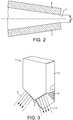
Figure 2 is a magnified sectional view of part of the conventional hand dryer described in European PatentEP1909627 ; -
Figure 3 is a schematic perspective view of a wall-mountable hand dryer in accordance with the present invention, shown in its normal orientation in use; -
Figure 4 is a perspective view from underneath the hand dryer shown inFigure 3 ; -
Figures 5a and 5b are perspective views - looking down on the dryer shown inFigure 3 - illustrating normal use of the dryer to dry the hands; -
Figure 6 is a perspective view of a moulded nozzle body for the hand dryer shown inFigure 3 ; -
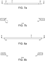
Figures 7a is an external front view of an elongate air slot machined using a disc cutter, intended to illustrate the end profile of the slot; -
Figure 7b is a sectional view along line A-A inFigure 7a , further illustrating the end profile of the slot; -
Figure 8a is an external front view of an elongate air slot machined using a slot drill, intended to illustrate the end profile of the slot; -
Figure 8b is a sectional view along the line B-B inFigure 8a , further illustrating the end profile of the slot; -
Figure 9 is a sectional view through a lower part of the dryer inFigure 3 , showing a bracing element moulded integrally as part of the nozzle body, with a slot which has been cut part-way into the bracing element using a flat-nosed cutting tool; -
Figure 10 is a view corresponding toFigure 9 , but illustrating a slot which has been cut part-way into the bracing element using a radiused cutting tool. -
Figure 3 shows a wall-mountable hand dryer 1 incorporating a nozzle part manufactured in accordance with the present invention. In this case, the nozzle part constitutes the mainexterior casing 3 of the hand dryer, which incorporates a pair of outlet apertures in the form of narrow, elongate air slots 5 - each approximately 0.8mm in width. The air slots are not easily visible inFigure 3 , but one of theslots 5 is shown more clearly inFigure 4 , provided on anunderside 7 of thedryer 1. - A motor-driven fan is provided inside the
main casing 3, which draws air throughintakes 9 on either side of themain casing 3 and forces the air at high speed (>100m/s) out through the narrowelongate air slots 5. - Each of the
elongate air slots 5 is sufficiently long to ensure that it spans the width of a typical user's hand when it is held - palm open - facing theslot 5. A length of between 120mm and 160mm is considered preferable for this. In use, thedryer 1 is mounted on awall 17. The user inserts his hands lengthwise front-to-back underneath theelongate air slots 5, as shown inFigure 5a , and high-speed air-sheets 11, 13 (Figure 3 ) are directed down onto the hands to 'scrape' water from the hands as they are subsequently withdrawn underneath theslots 5. This action is then repeated with the hands turned over to dry the reverse side of the hands (Figure 5b ). - The
elongate slots 5 need to be manufactured to strict tolerances: it has been found in accordance with the invention that even small variations in the width of theslots 5 can adversely affect the drying performance of thedryer 1. This is achieved conveniently and reliably in accordance with the present invention by first moulding a nozzle body - the nozzle body in this case being the main casing without the slots - and then post-machining theslots 5 into this nozzle body to form the finished main casing. - The
nozzle body 15 is shown inFigure 6 , viewed from the underneath so that theblank underside 7 is clearly visible. It may be injection-moulded from any suitable plastic, such as Polycarbonate (PC) or Acrylonitrile Butadiene Styrene (ABS), or a PC/ABS blend. - The
elongate slots 5 can be machined on a conventional CNC milling machine using a suitable milling cutter. - For example, a disc cutter may be used to cut the
slots 5.Figures 7a and 7b illustrates the resulting slot profile. A drawback with the use of a disc-cutter is that it produces aradiused end 19 to theslot 5, so that the cross-section of the slot 5 - as seen by the airflow - is not uniform. It has been found that this can adversely affect the flow structure around the edges of theslot 5. The problem can be reduced somewhat by increasing the disc cutter radius r1 (Figure 8b ), if this is practical, but only to a degree. In accordance with a further aspect of the invention, the problem is solved by using a slot drill to cut theslot 5 with astraight end 21, as shown inFigures 8a and 8b . - Part of the
nozzle body 15 can conveniently be moulded with integral bracing elements and then the slot may be post-machined into this part, so that the bracing elements act to brace the opposing walls of the slots against deformation. This helps maintain a more consistent slot width over the life cycle of the hand dryer.Figure 9 shows inclusion of a bracing element in the form of arib 23 on the inside of themain casing 3, extending between theunderside 7 of the casing and afront wall 25 of the casing. Theslot 5 is cut into theunderside 7 of the casing: part way into therib 23 to help prevent therib 23 acting as a dividing partition in theslot 5. -
Figure 9 shows a slot which has been cut with a flat-nosed slot drill. In this case, the squared-offend 27 of theslot 5 may act as a stress riser in therib 23. This can be addressed by using a radiused cutting tool such as a ball-nosed cutter or bull-nosed cutter, to create aradiused end 29 to theslot 5, as shown inFigure 10 . - The invention is not limited to the
particular hand dryer 1. For example, the invention may equally be used to manufacture a suitable nozzle part - possibly separate from the main casing - to replace the two-part nozzle in the hand dryer described inEP1909627 . If the nozzle part is formed separately from the main casing, then it may be sealed or joined to the main casing in similar manner to the existing two-part nozzle.
Claims (11)
- A method of manufacturing a hand dryer nozzle part, the nozzle part comprising a nozzle body (15) and an air outlet aperture in the nozzle body (15), the method comprising moulding the nozzle body (15) from plastic as a single part and then post-machining the air outlet aperture in the moulded plastic nozzle body (15) in the form of an elongate slot (5), a length of the slot (5) being less than 1.5mm in width; and characterised in that the slot (5) is machined into a part of the nozzle body (15) which is reinforced by one or more bracing elements (23) integrally moulded as part of the nozzle body (15).
- A method according to claim 1, wherein said length of the slot (5) is greater than 100mm.
- A method according to any preceding claim, in which the nozzle body (15) is moulded from Polycarbonate, or a blend of Polycarbonate and Acrylonitrile Butadiene Styrene.
- A method according to any preceding claim, in which the nozzle body (15) is injection-moulded.
- A method according to claim 1, wherein the bracing elements (23) are reinforcing ribs moulded on the inside of the nozzle body (15).
- A method according to claim 5, wherein the post-machining is carried out using a radiused cutting tool which cuts part way into the reinforcing ribs (23).
- A method according to any preceding claim, in which the nozzle body (15) constitutes, or forms part of, an external casing of the hand dryer(1).
- A hand dryer (1) having a nozzle part, the nozzle part comprising a plastic-moulded nozzle body (15) and a nozzle outlet aperture - through which drying air is ejected in use - which nozzle outlet aperture has been machined in the moulded nozzle body (15) in the form of an elongate slot (5), a length of the slot being less than 1.5mm in width, and characterised in that the slot (5) is machined into a part of the nozzle body (15) which is reinforced by one or more bracing elements (23) integrally moulded as part of the nozzle body (15).
- A hand dryer (1) according to claim 8, in which said length of the slot (5) is at least 120mm, for spanning the width of one or both of a user's hands held - palm open - facing the slot (5).
- A hand dryer (1) according to claim 8, wherein the bracing elements (23) are reinforcing ribs moulded on the inside of the nozzle body (15).
- A hand dryer (1) according to any of claims 8 to 10, wherein the nozzle body (15) is an external casing of the hand dryer (1).
Applications Claiming Priority (2)
| Application Number | Priority Date | Filing Date | Title |
|---|---|---|---|
| GB1118142.7A GB2495760B (en) | 2011-10-20 | 2011-10-20 | Developments in or relating to a hand dryer |
| PCT/GB2012/052474 WO2013057476A1 (en) | 2011-10-20 | 2012-10-05 | Method of manufacturing a nozzle part for a hand dryer |
Publications (2)
| Publication Number | Publication Date |
|---|---|
| EP2768369A1 EP2768369A1 (en) | 2014-08-27 |
| EP2768369B1 true EP2768369B1 (en) | 2017-08-23 |
Family
ID=45220015
Family Applications (1)
| Application Number | Title | Priority Date | Filing Date |
|---|---|---|---|
| EP12779147.3A Not-in-force EP2768369B1 (en) | 2011-10-20 | 2012-10-05 | Method of manufacturing a nozzle part for a hand dryer |
Country Status (6)
| Country | Link |
|---|---|
| US (1) | US9057560B2 (en) |
| EP (1) | EP2768369B1 (en) |
| JP (1) | JP5734939B2 (en) |
| CN (1) | CN103054502B (en) |
| GB (1) | GB2495760B (en) |
| WO (1) | WO2013057476A1 (en) |
Families Citing this family (10)
| Publication number | Priority date | Publication date | Assignee | Title |
|---|---|---|---|---|
| GB2495760B (en) * | 2011-10-20 | 2014-06-18 | Dyson Technology Ltd | Developments in or relating to a hand dryer |
| GB2508143B (en) | 2012-11-21 | 2015-05-13 | Dyson Technology Ltd | A hand dryer |
| GB2508144B (en) * | 2012-11-21 | 2015-05-13 | Dyson Technology Ltd | A hand dryer |
| CN105090067B (en) * | 2014-04-29 | 2019-07-16 | 德昌电机(深圳)有限公司 | Blower and hand dryer including it |
| GB2534176B (en) * | 2015-01-15 | 2018-08-08 | Dyson Technology Ltd | Motor mount |
| GB2543751B (en) | 2015-10-21 | 2019-04-24 | Dyson Technology Ltd | Motor mount |
| US10264931B2 (en) | 2016-09-23 | 2019-04-23 | The Boeing Company | Hand drying systems and methods |
| US11578918B2 (en) * | 2016-11-09 | 2023-02-14 | Airffect Gmbh | Handheld blower device |
| GB2562234B (en) * | 2017-05-08 | 2021-04-07 | Dyson Technology Ltd | A hand dryer |
| US10722083B2 (en) | 2017-10-03 | 2020-07-28 | Thunderhill Investments, LLC | Sanitary forced-air hand dryer |
Family Cites Families (29)
| Publication number | Priority date | Publication date | Assignee | Title |
|---|---|---|---|---|
| US3006079A (en) * | 1957-04-17 | 1961-10-31 | Sunbeam Corp | Hair dryer |
| US3401426A (en) * | 1966-05-31 | 1968-09-17 | New Britain Machine Co | Plastic injection molding machine |
| US3647147A (en) * | 1970-12-23 | 1972-03-07 | Norton Co | Spray nozzle orifice member |
| FR2242947B1 (en) * | 1973-09-11 | 1978-07-13 | Sfem | |
| US4126167A (en) * | 1976-12-06 | 1978-11-21 | Patient Care Products, Inc. | Gastric tube drainage bag |
| US4295233A (en) * | 1977-12-30 | 1981-10-20 | Whirlpool Corporation | Automatic hand washer and drier |
| US4756094A (en) * | 1984-10-31 | 1988-07-12 | Glenn Melvan Houck | Surface mountable air towel |
| US4642909A (en) * | 1985-02-27 | 1987-02-17 | Roy Garcia | Wall mounted hair dryer having adjustable outlet with multiple positions and directions |
| DE3627998C2 (en) * | 1986-08-18 | 1994-08-11 | Bosch Siemens Hausgeraete | Arrangement for lowering the temperature of hearth side walls |
| JPH08164088A (en) * | 1994-12-14 | 1996-06-25 | Oogaki Seiko Kk | Foot dryer |
| JPH09135788A (en) * | 1995-11-15 | 1997-05-27 | Matsushita Electric Ind Co Ltd | Hand drying equipment |
| US5823447A (en) * | 1996-08-27 | 1998-10-20 | Meritech, Inc. | Angled fan nozzle and unibody cylinder |
| US5819431A (en) * | 1997-01-10 | 1998-10-13 | Lancer; Harold | Foot dryer apparatus and method of drying feet |
| JP3585712B2 (en) * | 1997-04-16 | 2004-11-04 | 松下エコシステムズ株式会社 | Blow nozzle of hand dryer |
| US6038786A (en) * | 1998-04-16 | 2000-03-21 | Excel Dryer Inc. | Hand dryer |
| JP2003153823A (en) * | 2001-11-26 | 2003-05-27 | Matsushita Ecology Systems Co Ltd | Water droplet removing equipment |
| CA2470397A1 (en) * | 2001-12-08 | 2003-06-19 | Incro Limited | Method of manufacturing a nozzle arrangement |
| US6751886B2 (en) * | 2002-02-12 | 2004-06-22 | Vivrant, L.L.C. | Device for introduction of a substance into a propelled fluid |
| JP3760469B1 (en) * | 2004-10-01 | 2006-03-29 | 東陶機器株式会社 | Hand dryer |
| AU2006274711B2 (en) | 2005-07-30 | 2010-12-02 | Dyson Technology Limited | Dryer |
| GB0515744D0 (en) * | 2005-07-30 | 2005-09-07 | Dyson Technology Ltd | Dryer |
| JP3959546B2 (en) * | 2006-12-06 | 2007-08-15 | 三菱電機株式会社 | Hand dryer |
| TW200916038A (en) * | 2007-03-12 | 2009-04-16 | Alpha Technologies Corp Ltd | Improved airflow system & apparatus and method for airflow system |
| US20090119942A1 (en) * | 2007-11-14 | 2009-05-14 | Invent Resources, Inc. | Hand dryer |
| US8564444B2 (en) * | 2010-07-30 | 2013-10-22 | Toyota Motor Engineering & Manufacturing North America, Inc. | Mobile sanitizing devices and systems for dispensing sanitizer solution |
| US9267736B2 (en) * | 2011-04-18 | 2016-02-23 | Bradley Fixtures Corporation | Hand dryer with point of ingress dependent air delay and filter sensor |
| US9421291B2 (en) * | 2011-05-12 | 2016-08-23 | Fifth Third Bank | Hand dryer with sanitizing ionization assembly |
| US20120324755A1 (en) * | 2011-06-27 | 2012-12-27 | Zhao Shuai | Combination hair-hand dryer assembly, and blow drying method |
| GB2495760B (en) * | 2011-10-20 | 2014-06-18 | Dyson Technology Ltd | Developments in or relating to a hand dryer |
-
2011
- 2011-10-20 GB GB1118142.7A patent/GB2495760B/en not_active Expired - Fee Related
-
2012
- 2012-10-05 WO PCT/GB2012/052474 patent/WO2013057476A1/en not_active Ceased
- 2012-10-05 EP EP12779147.3A patent/EP2768369B1/en not_active Not-in-force
- 2012-10-18 JP JP2012230933A patent/JP5734939B2/en not_active Expired - Fee Related
- 2012-10-19 US US13/656,330 patent/US9057560B2/en not_active Expired - Fee Related
- 2012-10-22 CN CN201210402729.2A patent/CN103054502B/en not_active Expired - Fee Related
Non-Patent Citations (1)
| Title |
|---|
| None * |
Also Published As
| Publication number | Publication date |
|---|---|
| CN103054502B (en) | 2015-06-03 |
| EP2768369A1 (en) | 2014-08-27 |
| CN103054502A (en) | 2013-04-24 |
| GB2495760B (en) | 2014-06-18 |
| WO2013057476A1 (en) | 2013-04-25 |
| GB201118142D0 (en) | 2011-11-30 |
| GB2495760A (en) | 2013-04-24 |
| JP5734939B2 (en) | 2015-06-17 |
| US9057560B2 (en) | 2015-06-16 |
| US20130097885A1 (en) | 2013-04-25 |
| JP2013085961A (en) | 2013-05-13 |
Similar Documents
| Publication | Publication Date | Title |
|---|---|---|
| US9057560B2 (en) | Developments in or relating to a hand dryer | |
| KR100758415B1 (en) | Hand drying device | |
| CN101232833B (en) | dryer | |
| CN103052347B (en) | hand dryer | |
| JP4433093B2 (en) | Cross flow fan and air conditioner equipped with the same | |
| JP6419862B2 (en) | Lightweight board, connection configuration, and method of manufacturing connection configuration | |
| US20060202516A1 (en) | Cowl cover with integrated washer fluid passageway | |
| KR100457980B1 (en) | Air conditioner | |
| CN104640746B (en) | Air intake devices for vehicles | |
| KR102663783B1 (en) | Razor handle, razor comprising such handle, and method of manufacturing the same | |
| EP1909627B1 (en) | Dryer | |
| JP2006263152A (en) | Hand dryer | |
| WO2014116266A1 (en) | Backplate | |
| JP2012213585A (en) | Hand dryer | |
| CN101199402B (en) | hand dryer | |
| KR20130036424A (en) | Method for producing comb with various colors and anti-static and comb using the method | |
| CN101791203B (en) | hand dryer | |
| JPH11244191A (en) | Hand drying equipment | |
| US20040121128A1 (en) | Structural improvement of an injection molded blade | |
| JP5200235B2 (en) | End cap of extruded material and fixing method thereof | |
| HK1116373B (en) | Hand dryer | |
| JP2007183012A (en) | Indoor unit of air conditioner and cover member thereof, and wall embedding method of indoor unit | |
| HK1142252B (en) | Hand drying apparatus | |
| HK1118181B (en) | Hand drying apparatus |
Legal Events
| Date | Code | Title | Description |
|---|---|---|---|
| PUAI | Public reference made under article 153(3) epc to a published international application that has entered the european phase |
Free format text: ORIGINAL CODE: 0009012 |
|
| 17P | Request for examination filed |
Effective date: 20140331 |
|
| AK | Designated contracting states |
Kind code of ref document: A1 Designated state(s): AL AT BE BG CH CY CZ DE DK EE ES FI FR GB GR HR HU IE IS IT LI LT LU LV MC MK MT NL NO PL PT RO RS SE SI SK SM TR |
|
| DAX | Request for extension of the european patent (deleted) | ||
| 17Q | First examination report despatched |
Effective date: 20160428 |
|
| GRAP | Despatch of communication of intention to grant a patent |
Free format text: ORIGINAL CODE: EPIDOSNIGR1 |
|
| INTG | Intention to grant announced |
Effective date: 20170411 |
|
| GRAS | Grant fee paid |
Free format text: ORIGINAL CODE: EPIDOSNIGR3 |
|
| GRAA | (expected) grant |
Free format text: ORIGINAL CODE: 0009210 |
|
| AK | Designated contracting states |
Kind code of ref document: B1 Designated state(s): AL AT BE BG CH CY CZ DE DK EE ES FI FR GB GR HR HU IE IS IT LI LT LU LV MC MK MT NL NO PL PT RO RS SE SI SK SM TR |
|
| REG | Reference to a national code |
Ref country code: GB Ref legal event code: FG4D |
|
| REG | Reference to a national code |
Ref country code: CH Ref legal event code: EP |
|
| REG | Reference to a national code |
Ref country code: AT Ref legal event code: REF Ref document number: 920385 Country of ref document: AT Kind code of ref document: T Effective date: 20170915 |
|
| REG | Reference to a national code |
Ref country code: IE Ref legal event code: FG4D |
|
| REG | Reference to a national code |
Ref country code: DE Ref legal event code: R096 Ref document number: 602012036363 Country of ref document: DE |
|
| REG | Reference to a national code |
Ref country code: FR Ref legal event code: PLFP Year of fee payment: 6 |
|
| REG | Reference to a national code |
Ref country code: NL Ref legal event code: MP Effective date: 20170823 |
|
| REG | Reference to a national code |
Ref country code: LT Ref legal event code: MG4D |
|
| REG | Reference to a national code |
Ref country code: AT Ref legal event code: MK05 Ref document number: 920385 Country of ref document: AT Kind code of ref document: T Effective date: 20170823 |
|
| PG25 | Lapsed in a contracting state [announced via postgrant information from national office to epo] |
Ref country code: AT Free format text: LAPSE BECAUSE OF FAILURE TO SUBMIT A TRANSLATION OF THE DESCRIPTION OR TO PAY THE FEE WITHIN THE PRESCRIBED TIME-LIMIT Effective date: 20170823 Ref country code: LT Free format text: LAPSE BECAUSE OF FAILURE TO SUBMIT A TRANSLATION OF THE DESCRIPTION OR TO PAY THE FEE WITHIN THE PRESCRIBED TIME-LIMIT Effective date: 20170823 Ref country code: SE Free format text: LAPSE BECAUSE OF FAILURE TO SUBMIT A TRANSLATION OF THE DESCRIPTION OR TO PAY THE FEE WITHIN THE PRESCRIBED TIME-LIMIT Effective date: 20170823 Ref country code: HR Free format text: LAPSE BECAUSE OF FAILURE TO SUBMIT A TRANSLATION OF THE DESCRIPTION OR TO PAY THE FEE WITHIN THE PRESCRIBED TIME-LIMIT Effective date: 20170823 Ref country code: NO Free format text: LAPSE BECAUSE OF FAILURE TO SUBMIT A TRANSLATION OF THE DESCRIPTION OR TO PAY THE FEE WITHIN THE PRESCRIBED TIME-LIMIT Effective date: 20171123 Ref country code: NL Free format text: LAPSE BECAUSE OF FAILURE TO SUBMIT A TRANSLATION OF THE DESCRIPTION OR TO PAY THE FEE WITHIN THE PRESCRIBED TIME-LIMIT Effective date: 20170823 Ref country code: FI Free format text: LAPSE BECAUSE OF FAILURE TO SUBMIT A TRANSLATION OF THE DESCRIPTION OR TO PAY THE FEE WITHIN THE PRESCRIBED TIME-LIMIT Effective date: 20170823 |
|
| PG25 | Lapsed in a contracting state [announced via postgrant information from national office to epo] |
Ref country code: RS Free format text: LAPSE BECAUSE OF FAILURE TO SUBMIT A TRANSLATION OF THE DESCRIPTION OR TO PAY THE FEE WITHIN THE PRESCRIBED TIME-LIMIT Effective date: 20170823 Ref country code: LV Free format text: LAPSE BECAUSE OF FAILURE TO SUBMIT A TRANSLATION OF THE DESCRIPTION OR TO PAY THE FEE WITHIN THE PRESCRIBED TIME-LIMIT Effective date: 20170823 Ref country code: PL Free format text: LAPSE BECAUSE OF FAILURE TO SUBMIT A TRANSLATION OF THE DESCRIPTION OR TO PAY THE FEE WITHIN THE PRESCRIBED TIME-LIMIT Effective date: 20170823 Ref country code: GR Free format text: LAPSE BECAUSE OF FAILURE TO SUBMIT A TRANSLATION OF THE DESCRIPTION OR TO PAY THE FEE WITHIN THE PRESCRIBED TIME-LIMIT Effective date: 20171124 Ref country code: ES Free format text: LAPSE BECAUSE OF FAILURE TO SUBMIT A TRANSLATION OF THE DESCRIPTION OR TO PAY THE FEE WITHIN THE PRESCRIBED TIME-LIMIT Effective date: 20170823 Ref country code: BG Free format text: LAPSE BECAUSE OF FAILURE TO SUBMIT A TRANSLATION OF THE DESCRIPTION OR TO PAY THE FEE WITHIN THE PRESCRIBED TIME-LIMIT Effective date: 20171123 Ref country code: IS Free format text: LAPSE BECAUSE OF FAILURE TO SUBMIT A TRANSLATION OF THE DESCRIPTION OR TO PAY THE FEE WITHIN THE PRESCRIBED TIME-LIMIT Effective date: 20171223 |
|
| PG25 | Lapsed in a contracting state [announced via postgrant information from national office to epo] |
Ref country code: CZ Free format text: LAPSE BECAUSE OF FAILURE TO SUBMIT A TRANSLATION OF THE DESCRIPTION OR TO PAY THE FEE WITHIN THE PRESCRIBED TIME-LIMIT Effective date: 20170823 Ref country code: DK Free format text: LAPSE BECAUSE OF FAILURE TO SUBMIT A TRANSLATION OF THE DESCRIPTION OR TO PAY THE FEE WITHIN THE PRESCRIBED TIME-LIMIT Effective date: 20170823 Ref country code: RO Free format text: LAPSE BECAUSE OF FAILURE TO SUBMIT A TRANSLATION OF THE DESCRIPTION OR TO PAY THE FEE WITHIN THE PRESCRIBED TIME-LIMIT Effective date: 20170823 |
|
| REG | Reference to a national code |
Ref country code: DE Ref legal event code: R097 Ref document number: 602012036363 Country of ref document: DE |
|
| PG25 | Lapsed in a contracting state [announced via postgrant information from national office to epo] |
Ref country code: SK Free format text: LAPSE BECAUSE OF FAILURE TO SUBMIT A TRANSLATION OF THE DESCRIPTION OR TO PAY THE FEE WITHIN THE PRESCRIBED TIME-LIMIT Effective date: 20170823 Ref country code: IT Free format text: LAPSE BECAUSE OF FAILURE TO SUBMIT A TRANSLATION OF THE DESCRIPTION OR TO PAY THE FEE WITHIN THE PRESCRIBED TIME-LIMIT Effective date: 20170823 Ref country code: EE Free format text: LAPSE BECAUSE OF FAILURE TO SUBMIT A TRANSLATION OF THE DESCRIPTION OR TO PAY THE FEE WITHIN THE PRESCRIBED TIME-LIMIT Effective date: 20170823 Ref country code: MC Free format text: LAPSE BECAUSE OF FAILURE TO SUBMIT A TRANSLATION OF THE DESCRIPTION OR TO PAY THE FEE WITHIN THE PRESCRIBED TIME-LIMIT Effective date: 20170823 Ref country code: SM Free format text: LAPSE BECAUSE OF FAILURE TO SUBMIT A TRANSLATION OF THE DESCRIPTION OR TO PAY THE FEE WITHIN THE PRESCRIBED TIME-LIMIT Effective date: 20170823 |
|
| REG | Reference to a national code |
Ref country code: CH Ref legal event code: PL |
|
| PLBE | No opposition filed within time limit |
Free format text: ORIGINAL CODE: 0009261 |
|
| STAA | Information on the status of an ep patent application or granted ep patent |
Free format text: STATUS: NO OPPOSITION FILED WITHIN TIME LIMIT |
|
| REG | Reference to a national code |
Ref country code: IE Ref legal event code: MM4A |
|
| PG25 | Lapsed in a contracting state [announced via postgrant information from national office to epo] |
Ref country code: LI Free format text: LAPSE BECAUSE OF NON-PAYMENT OF DUE FEES Effective date: 20171031 Ref country code: CH Free format text: LAPSE BECAUSE OF NON-PAYMENT OF DUE FEES Effective date: 20171031 Ref country code: LU Free format text: LAPSE BECAUSE OF NON-PAYMENT OF DUE FEES Effective date: 20171005 |
|
| 26N | No opposition filed |
Effective date: 20180524 |
|
| REG | Reference to a national code |
Ref country code: BE Ref legal event code: MM Effective date: 20171031 |
|
| PG25 | Lapsed in a contracting state [announced via postgrant information from national office to epo] |
Ref country code: SI Free format text: LAPSE BECAUSE OF FAILURE TO SUBMIT A TRANSLATION OF THE DESCRIPTION OR TO PAY THE FEE WITHIN THE PRESCRIBED TIME-LIMIT Effective date: 20170823 Ref country code: BE Free format text: LAPSE BECAUSE OF NON-PAYMENT OF DUE FEES Effective date: 20171031 |
|
| PG25 | Lapsed in a contracting state [announced via postgrant information from national office to epo] |
Ref country code: MT Free format text: LAPSE BECAUSE OF NON-PAYMENT OF DUE FEES Effective date: 20171005 |
|
| REG | Reference to a national code |
Ref country code: FR Ref legal event code: PLFP Year of fee payment: 7 |
|
| PG25 | Lapsed in a contracting state [announced via postgrant information from national office to epo] |
Ref country code: IE Free format text: LAPSE BECAUSE OF NON-PAYMENT OF DUE FEES Effective date: 20171005 |
|
| PGFP | Annual fee paid to national office [announced via postgrant information from national office to epo] |
Ref country code: GB Payment date: 20180814 Year of fee payment: 7 |
|
| PG25 | Lapsed in a contracting state [announced via postgrant information from national office to epo] |
Ref country code: HU Free format text: LAPSE BECAUSE OF FAILURE TO SUBMIT A TRANSLATION OF THE DESCRIPTION OR TO PAY THE FEE WITHIN THE PRESCRIBED TIME-LIMIT; INVALID AB INITIO Effective date: 20121005 |
|
| PG25 | Lapsed in a contracting state [announced via postgrant information from national office to epo] |
Ref country code: CY Free format text: LAPSE BECAUSE OF NON-PAYMENT OF DUE FEES Effective date: 20170823 |
|
| PGFP | Annual fee paid to national office [announced via postgrant information from national office to epo] |
Ref country code: FR Payment date: 20190918 Year of fee payment: 8 |
|
| PG25 | Lapsed in a contracting state [announced via postgrant information from national office to epo] |
Ref country code: MK Free format text: LAPSE BECAUSE OF FAILURE TO SUBMIT A TRANSLATION OF THE DESCRIPTION OR TO PAY THE FEE WITHIN THE PRESCRIBED TIME-LIMIT Effective date: 20170823 |
|
| PGFP | Annual fee paid to national office [announced via postgrant information from national office to epo] |
Ref country code: DE Payment date: 20190918 Year of fee payment: 8 |
|
| PG25 | Lapsed in a contracting state [announced via postgrant information from national office to epo] |
Ref country code: TR Free format text: LAPSE BECAUSE OF FAILURE TO SUBMIT A TRANSLATION OF THE DESCRIPTION OR TO PAY THE FEE WITHIN THE PRESCRIBED TIME-LIMIT Effective date: 20170823 |
|
| PG25 | Lapsed in a contracting state [announced via postgrant information from national office to epo] |
Ref country code: PT Free format text: LAPSE BECAUSE OF FAILURE TO SUBMIT A TRANSLATION OF THE DESCRIPTION OR TO PAY THE FEE WITHIN THE PRESCRIBED TIME-LIMIT Effective date: 20170823 |
|
| PG25 | Lapsed in a contracting state [announced via postgrant information from national office to epo] |
Ref country code: AL Free format text: LAPSE BECAUSE OF FAILURE TO SUBMIT A TRANSLATION OF THE DESCRIPTION OR TO PAY THE FEE WITHIN THE PRESCRIBED TIME-LIMIT Effective date: 20170823 |
|
| GBPC | Gb: european patent ceased through non-payment of renewal fee |
Effective date: 20191005 |
|
| PG25 | Lapsed in a contracting state [announced via postgrant information from national office to epo] |
Ref country code: GB Free format text: LAPSE BECAUSE OF NON-PAYMENT OF DUE FEES Effective date: 20191005 |
|
| REG | Reference to a national code |
Ref country code: DE Ref legal event code: R119 Ref document number: 602012036363 Country of ref document: DE |
|
| PG25 | Lapsed in a contracting state [announced via postgrant information from national office to epo] |
Ref country code: DE Free format text: LAPSE BECAUSE OF NON-PAYMENT OF DUE FEES Effective date: 20210501 Ref country code: FR Free format text: LAPSE BECAUSE OF NON-PAYMENT OF DUE FEES Effective date: 20201031 |