EP2768161A1 - Uni-Fiber Lasercom Terminal Design - Google Patents
Uni-Fiber Lasercom Terminal Design Download PDFInfo
- Publication number
- EP2768161A1 EP2768161A1 EP20140155393 EP14155393A EP2768161A1 EP 2768161 A1 EP2768161 A1 EP 2768161A1 EP 20140155393 EP20140155393 EP 20140155393 EP 14155393 A EP14155393 A EP 14155393A EP 2768161 A1 EP2768161 A1 EP 2768161A1
- Authority
- EP
- European Patent Office
- Prior art keywords
- signal
- terminal
- ferrule
- optical fiber
- lens
- Prior art date
- Legal status (The legal status is an assumption and is not a legal conclusion. Google has not performed a legal analysis and makes no representation as to the accuracy of the status listed.)
- Granted
Links
Images




Classifications
-
- H—ELECTRICITY
- H04—ELECTRIC COMMUNICATION TECHNIQUE
- H04B—TRANSMISSION
- H04B10/00—Transmission systems employing electromagnetic waves other than radio-waves, e.g. infrared, visible or ultraviolet light, or employing corpuscular radiation, e.g. quantum communication
- H04B10/40—Transceivers
-
- H—ELECTRICITY
- H04—ELECTRIC COMMUNICATION TECHNIQUE
- H04B—TRANSMISSION
- H04B10/00—Transmission systems employing electromagnetic waves other than radio-waves, e.g. infrared, visible or ultraviolet light, or employing corpuscular radiation, e.g. quantum communication
- H04B10/11—Arrangements specific to free-space transmission, i.e. transmission through air or vacuum
- H04B10/112—Line-of-sight transmission over an extended range
- H04B10/1123—Bidirectional transmission
- H04B10/1125—Bidirectional transmission using a single common optical path
-
- G—PHYSICS
- G02—OPTICS
- G02B—OPTICAL ELEMENTS, SYSTEMS OR APPARATUS
- G02B26/00—Optical devices or arrangements for the control of light using movable or deformable optical elements
- G02B26/08—Optical devices or arrangements for the control of light using movable or deformable optical elements for controlling the direction of light
- G02B26/0816—Optical devices or arrangements for the control of light using movable or deformable optical elements for controlling the direction of light by means of one or more reflecting elements
- G02B26/0833—Optical devices or arrangements for the control of light using movable or deformable optical elements for controlling the direction of light by means of one or more reflecting elements the reflecting element being a micromechanical device, e.g. a MEMS mirror, DMD
- G02B26/0858—Optical devices or arrangements for the control of light using movable or deformable optical elements for controlling the direction of light by means of one or more reflecting elements the reflecting element being a micromechanical device, e.g. a MEMS mirror, DMD the reflecting means being moved or deformed by piezoelectric means
Definitions
- the present disclosure relates to laser communications (lasercom) terminals.
- laser communications lasercom
- a uni-fiber lasercom terminal a uni-fiber lasercom terminal.
- the present disclosure relates to a system, method, and apparatus for uni-fiber laser communications (lasercom) terminals.
- the disclosed method for a uni-fiber (i.e. a single optical fiber) lasercom terminal involves generating, with an oscillator, a first signal having a first wavelength ( ⁇ 1 ).
- the method further involves modulating, with a modulator, the first signal.
- the method involves circulating, with a circulator, the first signal.
- the method involves amplifying, with a bi-directional optical amplifier (optical amp), the first signal.
- the method involves transmitting, through an optical fiber, the first signal.
- the optical fiber is embedded in a ferrule, and an end of the ferrule is coated with a reflective coating.
- the method involves transmitting, through at least one lens, the first signal. Additionally, the method involves receiving, through at least one lens and the optical fiber, the first signal. Also, the method involves amplifying, with the bi-directional optical amp, the first signal. Additionally, the method involves circulating, with the circulator, the first signal. In addition, the method involves detecting, with an acquisition detector, the first signal. Further, the method involves nutating and translating, with an actuator associated with the ferrule, the ferrule according to feedback from the acquisition detector regarding the first signal.
- the method further involves receiving, through at least one lens and the optical fiber, a second signal having a second wavelength ( ⁇ 2 ).
- the method further involves amplifying, with the bi-directional optical amp, the second signal.
- the method further involves circulating, with the circulator, the second signal.
- the method further involves separating, with a wavelength division multiplexer (WDM), a third signal (which comprises the first signal and the second signal) into the first signal and the second signal.
- WDM wavelength division multiplexer
- the method further involves detecting, with a communication detector, the second signal.
- the method further involves reflecting the first signal and/or the second signal off at least one mirror associated with at least one lens.
- at least one of the mirrors is capable of being gimbaled.
- the actuator is a piezo-electric actuator.
- the reflective coating on the end of the ferrule is a cat's eye reflector.
- the detecting of the first signal by the acquisition detector is achieved by time division multiple access (TDMA) and/or correlation detection.
- TDMA time division multiple access
- the optical fiber and/or the ferrule are tapered to minimize backreflection.
- a uni-fiber lasercom terminal apparatus includes an oscillator to generate a first signal having a first wavelength ( ⁇ 1 ).
- the apparatus further includes a modulator to modulate the first signal.
- the apparatus includes a circulator to circulate the first signal.
- the apparatus includes a bi-directional optical amp to amplify the first signal.
- the apparatus includes an optical fiber; where the optical fiber is embedded in a ferrule, and an end of the ferrule is coated with a reflective coating.
- the apparatus includes at least one lens.
- the first signal is transmitted through and is received through the optical fiber and at least one lens.
- the apparatus includes an acquisition detector to detect the first signal. Further, the apparatus includes an actuator associated with the ferrule to nutate and translate the ferrule according to feedback from the acquisition detector regarding the first signal.
- the bi-directional optical amp of the apparatus is further to amplify a second signal, having a second wavelength ( ⁇ 2 ), that is received through the optical fiber and at least one lens.
- the circulator of the apparatus is further to circulate the second signal.
- the apparatus further includes a WDM to separate a third signal (which comprises the first signal and the second signal) into the first signal and the second signal.
- the apparatus further includes a communication detector to detect the second signal.
- the apparatus further includes at least one mirror, associated with at least one lens, to reflect the first signal and/or the second signal.
- at least one of the mirrors is capable of being gimbaled.
- the acquisition detector detects the first signal by TDMA and/or correlation detection.
- a method for operating a uni-fiber lasercom terminal system involves generating, with an oscillator associated with a first terminal, a first signal having a first wavelength ( ⁇ 1 ). The method further involves modulating, with a modulator associated with the first terminal, the first signal. Also, the method involves circulating, with a circulator associated with the first terminal, the first signal. In addition, the method involves amplifying, with a bi-directional optical amp associated with the first terminal, the first signal. Additionally, the method involves transmitting, through an optical fiber associated with the first terminal, the first signal. In one or more embodiments, the optical fiber is embedded in a ferrule, and an end of the ferrule is coated with a reflective coating.
- the method involves transmitting, through at least one lens associated with the first terminal, the first signal. Additionally, the method involves reflecting, by a reflective surface associated with a second terminal, the first signal. Also, the method involves receiving, by the first terminal through at least one lens associated with the first terminal and the optical fiber associated with the first terminal, the reflected first signal. In addition, the method involves amplifying, with the bi-directional optical amp associated with the first terminal, the reflected first signal. Additionally, the method involves circulating, with the circulator associated with the first terminal, the reflected first signal. Also, the method involves detecting, with an acquisition detector associated with the first terminal, the reflected first signal. The method further involves nutating and translating, with an actuator associated with the ferrule of the first terminal, the ferrule of the first terminal according to feedback from the acquisition detector regarding the reflected first signal.
- the method further involves receiving, by the first terminal through at least one lens associated with the first terminal and the optical fiber associated with the first terminal, a second signal from the second terminal, where the second signal has a second wavelength ( ⁇ 2 ).
- the method further involves amplifying, with the bi-directional optical amp associated with the first terminal, the second signal.
- the method further involves circulating, with the circulator associated with the first terminal, the second signal.
- the method further involves separating, with a WDM associated with the first terminal, a third signal (which comprises the first signal and the second signal) into the first signal and the second signal.
- the method further involves detecting, with a communication detector associated with the first terminal, the second signal.
- the method further involves reflecting the first signal and/or the second signal off at least one mirror associated with at least one lens associated with the first terminal.
- at least one of the mirrors of the first terminal is capable of being gimbaled.
- the reflective surface associated with the second terminal is a cat's eye reflector.
- a system for uni-fiber lasercom terminals includes an oscillator, associated with a first terminal, to generate a first signal having a first wavelength ( ⁇ 1 ).
- the system further includes a modulator, associated with the first terminal, to modulate the first signal.
- the system includes a circulator, associated with the first terminal, to circulate the first signal.
- the system includes a bi-directional optical amp, associated with the first terminal, to amplify the first signal.
- the system includes an optical fiber associated with the first terminal, where the optical fiber is embedded in a ferrule, and an end of the ferrule is coated with a reflective coating.
- the system includes at least one lens associated with the first terminal.
- the first signal is transmitted through and is received through the optical fiber associated with the first terminal and at least one lens associated with the first terminal.
- the system includes a reflective surface, associated with a second terminal, to reflect the first signal.
- the system includes an acquisition detector, associated with the first terminal, to detect the reflected first signal.
- the system includes an actuator, associated with the ferrule of the first terminal, to nutate and translate the ferrule of the first terminal according to feedback from the acquisition detector regarding the reflected first signal.
- the bi-directional optical amp, associated with the first terminal is further to amplify a second signal, from the second terminal and having a second wavelength ( ⁇ 2 ), that is received through the optical fiber associated with the first terminal and at least one lens associated with the first terminal.
- the circulator, associated with the first terminal is further to circulate the second signal.
- the system further includes a WDM, associated with the first terminal, to separate a third signal (which comprises the first signal and the second signal) into the first signal and the second signal.
- the system further includes a communication detector, associated with the first terminal, to detect the second signal.
- the system further includes at least one mirror, associated with at least one lens of the first terminal, to reflect the first signal and/or the second signal.
- at least one of the mirrors of the first terminal is capable of being gimbaled.
- the reflective coating on the end of the ferrule of the first terminal is a cat's eye reflector.
- the acquisition detector, associated with the first terminal detects the reflected first signal by TDMA and/or correlation detection.
- the reflective surface associated with the second terminal is a cat's eye reflector.
- the methods and apparatus disclosed herein provide an operative system for a uni-fiber (i.e. a single optical fiber) laser communications (lasercom) terminal.
- This disclosed system employs a simple and efficient uni-fiber lasercom terminal.
- the uni-fiber lasercom terminal design minimizes the amount of hardware required without sacrificing sensitivity.
- a single optical fiber is used for all signals, including but not limited to: the transmit beacon signal, the transmit communication signal, the receive acquisition signal, and the receive communication signal.
- the uni-fiber design of the uni-fiber lasercom terminal is enabled by the use of several features that are not commonly found in conventional lasercom terminals. Specifically, these features include, but are not limited to, a cat's eye reflector to assist in acquisition, a unique fiber ferrule designed to bring the reflector as close to the fiber core as possible while minimizing back-reflection of the fiber transmit signal, a special acquisition pulse code for transmit/receive isolation of a single wavelength, and a bi-directional optical amplifier (optical amp) to provide amplification for all signal paths.
- a cat's eye reflector to assist in acquisition
- a unique fiber ferrule designed to bring the reflector as close to the fiber core as possible while minimizing back-reflection of the fiber transmit signal
- a special acquisition pulse code for transmit/receive isolation of a single wavelength
- a bi-directional optical amplifier optical amp
- the optical head to be simplified to a single actuated fiber at the back focal plane of a focusing element (e.g., a lens or a reflective telescope), thereby making the uni-fiber lasercom terminal easy to integrate onto platforms with low payload size, weight, and power (SWaP) capabilities.
- a focusing element e.g., a lens or a reflective telescope
- SWaP payload size, weight, and power
- FIG. 1 shows a schematic diagram of a uni-fiber (i.e. a single optical fiber) laser communications (lasercom) terminal 100, in accordance with at least one embodiment of the present disclosure.
- FIG. 2 shows a schematic diagram of a second uni-fiber laser lasercom terminal 200 to be used in conjunction with the uni-fiber lasercom terminal 100 (i.e. the first terminal) of FIG. 1 , in accordance with at least one embodiment of the present disclosure. It should be noted that the design of the second terminal 200 of FIG.
- the master oscillator 110 of the first terminal 100 generates a first signal having a first wavelength ( ⁇ 1 ) and the master oscillator 210 of the second terminal 200 generates a second signal having a second wavelength ( ⁇ 2 );
- the acquisition detector 195 of the first terminal 100 detects a first signal having a first wavelength ( ⁇ 1 ) and the acquisition detector 295 of the second terminal 200 detects a second signal having a second wavelength ( ⁇ 2 );
- the communication detector 197 of the first terminal 100 detects a second signal having a second wavelength ( ⁇ 2 ) and the communication detector 297 of the second terminal 200 detects a first signal having a first wavelength ( ⁇ 1 ).
- the modulator 120 of the first terminal 100 and the modulator 220 of the second terminal 200 are the same, the circulator 130 of the first terminal 100 and the circulator 230 of the second terminal 200 are the same, the bi-directional optical amplifier (optical amp) 140 of the first terminal 100 and the bi-directional optical amp 240 of the second terminal 200 are the same, the wavelength division multiplexer (WDM) 190 of the first terminal 100 and the WDM 290 of the second terminal 200 are the same, the ferrule 150 of the first terminal 100 and the ferrule 250 of the second terminal 200 are the same, the lens 170 of the first terminal 100 and the lens 270 of the second terminal 200 are the same, the gimbaled mirror 180 of the first terminal 100 and the gimbaled mirror 280 of the second terminal 200 are the same, and the piezo-electric actuator 152 of the first terminal 100 and the piezo-electric actuator 252 of the second terminal 200 are the same.
- WDM wavelength division multiplexer
- both the terminal 100 of FIG. 1 and the terminal of FIG. 2 include a filter(s) (not depicted in FIGS. 1 and 2 ) to filter the received signals (i.e. the first signal and the second signal), and the filter(s) is located prior to the detectors (i.e. the communication detectors 197, 297 and the acquisition detectors 195, 295).
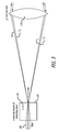
- FIG. 3 shows a diagram of the ferrule 150 surrounding the optical fiber 160 and the lens 170 of the uni-fiber lasercom terminal 100 of FIG. 1 , in accordance with at least one embodiment of the present disclosure.
- FIGS. 1 , 2 , and 3 will be described in combination with one another.
- a master oscillator 110 is shown to generate the first signal having a first wavelength ( ⁇ 1 ).
- a modulator 120 is then used to modulate the first signal.
- a circulator 130 circulates the first signal to a bi-directional optical amp 140.
- the bi-directional optical amp 140 then amplifies the first signal. Once the first signal is amplified by the bi-directional optical amp 140, the first signal passes through a ferrule 150 surrounding the optical fiber 160.
- the ferrule 150 of the first terminal 100 is manufactured from light-absorbing glass (or, alternatively, from other materials), and the ferrule 150 is approximately greater than or equal to ( ⁇ ) one (1) millimeter (mm) in diameter.
- the input/output end of the ferrule 150 surrounding the optical fiber 160 is coated with a high reflective coating 155, which creates a cat's eye reflector.
- the input/output tip of the optical fiber 160 is coated with an anti-reflection coating 153.
- the fiber and ferrule may be tapered to minimize backreflection of the transmitted signal by reflective coating 155.
- the lens 170 is approximately ⁇ 1 inch in diameter and located approximately one focal length away from the fiber.
- the ferrule 250 of the second terminal 200 is manufactured from light-absorbing glass (or, alternatively, from other materials); the ferrule 250 is approximately ⁇ 1 mm in diameter; the input/output end of the ferrule 250 surrounding the optical fiber 260 is coated with a high reflective coating 255, which creates a cat's eye reflector; the input/output tip of the optical fiber 260 is coated with an anti-reflection coating 253; the fiber and ferrule may be tapered to minimize backreflection of the transmitted signal by reflective coating 255; and the lens 270 is approximately ⁇ 1 inch in diameter and located approximately one focal length away from the fiber.
- the first signal passes through a ferrule 150 surrounding the optical fiber 160 of the first terminal 100
- the first signal is then propagated through a lens 170 of the first terminal 100, reflected off a gimbaled mirror 180 of the first terminal 100, and transmitted to a second terminal 200.
- more than one lens 170, 270 may be employed by the first terminal 100 and/or the second terminal 200.
- the mirror 180, 280 of the first terminal 100 and/or the second terminal 200 may or may not be manufactured to have gimballing capability. Additionally, it should be noted that more than one mirror 180, 280 may be employed by the first terminal 100 and/or the second terminal 200.
- the first signal reflects off of a reflective coating 255 on an end of the ferrule 250 surrounding the optical fiber 260 of the second terminal 200.
- the first signal is reflected back to the first terminal 100.
- the first signal is then reflected off the gimbaled mirror 180 of the first terminal, and propagated through the lens 170 and the optical fiber 160 of the first terminal 100.
- the master oscillator 210 of the second terminal 200 optionally (i.e. for embodiments where the first terminal 100 is not a transmit only a communications system, but rather is a transmit and receive communications system), the master oscillator 210 of the second terminal 200 generates a second signal having a second wavelength ( ⁇ 2 ), for example a second signal XXX.
- a modulator 220 is then used to modulate the second signal.
- a second circulator 230 circulates the second signal to a second bi-directional optical amp 240.
- the second bi-directional optical amp 240 then amplifies the second signal. Once the second signal is amplified by the second bi-directional optical amp 240, the second signal passes through the second ferrule 250 surrounding the second optical fiber 260.
- the second signal is then propagated through a second lens 270 of the second terminal 200, reflected off a second mirror 280 of the second terminal 200, and transmitted to the first terminal 100.
- the second signal is then reflected off the gimbaled mirror 180 of the first terminal 100, and propagated through the lens 170 and optical fiber 160 of the first terminal 100.
- the bi-directional optical amp 140 of the first terminal 100 amplifies a third signal, which comprises the reflected first signal and/or the second signal.
- the circulator 130 circulates the amplified third signal to a wavelength division multiplexer (WDM) 190.
- WDM wavelength division multiplexer
- the WDM 190 then separates the third signal into the first reflected signal and/or the second signal.
- an acquisition detector 195 detects the first reflected signal
- a communication detector 197 detects the second signal.
- a piezo-electric actuator 152 associated with the ferrule 150 nutates the ferrule 150 to generate a tracking signal and translates the ferrule 150 into proper alignment according to feedback from the acquisition detector 195 regarding the reflected first signal. It should be noted that in other embodiments, the ferrule 150 may be nutated and/or translated by means other than by a piezo-electric actuator 152.
- FIG. 4 shows a flow chart for the method 400 of operation of the first terminal 100 of FIG. 1 in conjunction with the second terminal 200 of FIG. 2 , in accordance with at least one embodiment of the present disclosure.
- an oscillator associated with the first terminal generates a first signal having a first wavelength ( ⁇ 1 ) 410.
- a modulator associated with the first terminal then modulates the first signal 415.
- a circulator associated with the first terminal circulates the first signal 420.
- a bi-directional optical amp associated with the first terminal amplifies the first signal 425. After the first signal is amplified, the first signal is transmitted through an optical fiber associated with the first terminal and through at least one lens associated with the first terminal 430.
- the first signal is then reflected by a reflective surface of the second terminal 435. Then, the reflected first signal and a second signal, which is transmitted from the second terminal and has a second wavelength ( ⁇ 2 ). are received through at least one lens associated with the first terminal and the optical fiber of the first terminal 440.
- the bi-directional optical amp associated with the first terminal amplifies the reflected first signal and the second signal 445.
- the circulator associated with the first terminal circulates the reflected first signal and the second signal 450.
- a wavelength division multiplexer (WDM) associated with the first terminal separates a third signal (which comprises the reflected first signal and/or the second signal) into the reflected first signal and/or the second signal 455.
- WDM wavelength division multiplexer
- an actuator associated with the first terminal, nutates and translates the ferrule surrounding the optical fiber of the first terminal according to feedback from the acquisition detector of the first terminal regarding the reflected first signal 465.
- a communication detector associated with the first terminal detects the second signal 470. Then, the method 400 ends 475.
- the transmitted (TX) acquisition signal e.g., the transmitted first signal having a first wavelength ( ⁇ 1 ) from the first terminal 100 of FIG. 1
- the received (RX) acquisition signal e.g., the reflected first signal having a first wavelength ( ⁇ 1 ), which is the first signal reflected off of the second terminal 200 of FIG. 2 .
- TX transmitted
- RX received
- FIGS. 5A, 5B, and 5C Three exemplary techniques are illustrated in FIGS. 5A, 5B, and 5C .
- FIG. 5A shows a graph 500 depicting a first technique, based on time division multiple access (TDMA), for isolation of the transmitted and the reflected first signal, in accordance with at least one embodiment of the present disclosure.
- a pulse train 510 of transmit acquisition signals (Tx 1 , Tx 2 ) is transmitted at a specific time interval such that the return pulses 520 of the receive acquisition signals (Rx 1 , Rx 2 ) will arrive approximately half-way in between the transmit pulses 510.
- an expected range i.e. distance
- the pulse rate would be approximately from 0.7 to 7 kilopulses per second (kpps), which would be undesirably slow for conventional optical amps.
- FIG. 5B shows a graph 530 depicting a second technique, based on TDMA, for isolation of the transmitted and the reflected first signal, in accordance with at least one embodiment of the present disclosure.
- the rate of the pulse train 540 of the transmit acquisition signals (Tx 1 , Tx 2 ) is increased such that multiple transmit pulses 540 remain in flight.
- This technique requires a more accurate knowledge of the range between the terminals to keep the return pulses 550 of the receive acquisition signals (Rx 1 , Rx 2 ) in between the transmit pulses 540.
- Mpps 0.5 megapulses per second
- FIG. 5C shows a graph 560 depicting a third technique, based on correlation detection, for isolation of the transmitted and the reflected first signal, in accordance with at least one embodiment of the present disclosure.
- pulse code words (Tx Word 1 , Tx Word 2 ) 570 are transmitted and return code words (Rx Word 1 , Rx Word 2 ) 580 are received.
- a correlation decoder is used to decode the return pulses 590.
- the range between the terminals only needs to be known (or derived) to within 1.1 km of accuracy in order to achieve 1 Mbps of on-off keying (OOK) code with a 31 bit code word length.
- OOK on-off keying
- various correlation techniques may be employed including, but not limited to, auto correlation, matched filter, Kalman filter, and hypothesis testing.
- FIG. 6 shows a schematic diagram of a uni-fiber lasercom terminal 600 that utilizes the isolation technique of FIG. 5C , in accordance with at least one embodiment of the present disclosure.
- the design of the terminal 600 of FIG. 6 is the same as the design of the first terminal 100 of FIG.1 except for that the terminal 600 of FIG. 6 includes additional components including, but not limited to, two correlation decoders 610, 620, two additional acquisition detectors 630, 640, two nutation tracking units 650, 660, a transmit blanking unit 670, and a communication demodulator 680.
- the correlation decoders 620, 610 are used to decode the received reflected first signal and the second signal, respectively.
- the transmit blanking unit 670 is used to remove the transmit pulses from the reflected first signal, which has a first wavelength ( ⁇ 1 ).
- the acquisition detectors 640, 630 are used to detect the receive pulses from the reflected first signal and the second signal, respectively.
- the nutation tracking units 660, 650 are used to provide feedback to the piezo-electric actuator 152 regarding the first reflected signal and the second signal, respectively.
- the communication demodulator 680 is used to demodulate the detected second signal.
- FIG. 7 shows a flow chart for the method 700 of operation of the terminal 100 in FIG. 1 acquiring, tracking, and communicating with the terminal 200 of FIG. 2 , in accordance with at least one embodiment of the present disclosure.
- the first terminal transmits a first signal having a first wavelength ( ⁇ 1 ) 720.
- the first terminal moves its gimbal (e.g., gimbals its mirror(s)) to scan the range of possible angles containing the second terminal 730.
- the first signal illuminates the second terminal, the first signal refects off the second cat's eye reflector (i.e. the cat's eye reflector on the second terminal), is focused into the first fiber (i.e.
- the first terminal uses an error signal, created by the modulation of the first signal by the first fiber nutation, to adjust the translation of the first fiber to track the second terminal 750.
- the second terminal transmits a second signal having a second wavelength ( ⁇ 2 ) and follows all of the steps of this method concurrent with the first terminal (i.e. steps 720-780) 760.
- the first terminal detects the wavelength of the second terminal (i.e. the second wavelength)
- the first terminal switches to tracking off an error signal created by the modulation of the second signal by the first fiber nutation 770.
- the first terminal then switches the modulation of the first signal from the acquisition waveform (i.e. the waveform of FIG. 5 ) to the communication waveform (i.e. the waveform used to send data to the communication detector in the second terminal) 780. Then, the method 700 ends 790.
- the acquisition waveform i.e. the waveform of FIG. 5
- the communication waveform i.e. the waveform used to send data to the communication detector in the second terminal
- FIG. 8 shows a chart 800 illustrating the advantages of the disclosed uni-fiber lasercom terminal design over a conventional lasercom terminal design, in accordance with at least one embodiment of the present disclosure.
- this chart 800 shows the advantages of a number of features of the disclosed uni-fiber lasercom terminal design over the features of a conventional lasercom terminal design.
- One advantage relates to the feature of aperture size.
- the disclosed uni-fiber design has an aperture size of only 1.0 inch, while the comparable conventional terminal design has an aperture size of 3.5 inches.
- a second advantage relates to the feature of the optical head dimensions.
- the disclosed uni-fiber design has optical head dimensions of only 3 inches x 4 inches x 7 inches, while the comparable conventional terminal design has optical head dimensions of 13.5 inches x 13.5 inches x 24.0 inches.
- a third advantage relates to the feature of mass (i.e. the mass for the optics and the electronics).
- the disclosed uni-fiber design has a mass of only 5 pounds (lbs) for the optics and a mass of 54 lbs for the electronics, while the comparable conventional terminal design has a mass of 50 lbs for the optics and a mass of 54 lbs for the electronics.
- a fourth advantage relates to the feature of transmit (Tx) power.
- the disclosed uni-fiber design has a transmit power of 250 milliwatts (mW), while the comparable conventional terminal design has a transmit power of 500 mW.
- a fifth advantage relates to the feature of power consumption.
- the disclosed uni-fiber design consumes only 60 Watts (W) of power, while the comparable conventional terminal design consumes 82 W of power.
Landscapes
- Physics & Mathematics (AREA)
- Electromagnetism (AREA)
- Engineering & Computer Science (AREA)
- Computer Networks & Wireless Communication (AREA)
- Signal Processing (AREA)
- General Physics & Mathematics (AREA)
- Optics & Photonics (AREA)
- Optical Communication System (AREA)
- Optical Couplings Of Light Guides (AREA)
Abstract
Description
- The present disclosure relates to laser communications (lasercom) terminals. In particular, it relates to a uni-fiber lasercom terminal.
- The present disclosure relates to a system, method, and apparatus for uni-fiber laser communications (lasercom) terminals. In particular, the disclosed method for a uni-fiber (i.e. a single optical fiber) lasercom terminal involves generating, with an oscillator, a first signal having a first wavelength (λ1). The method further involves modulating, with a modulator, the first signal. Also, the method involves circulating, with a circulator, the first signal. In addition, the method involves amplifying, with a bi-directional optical amplifier (optical amp), the first signal. Additionally, the method involves transmitting, through an optical fiber, the first signal. In one or more embodiments, the optical fiber is embedded in a ferrule, and an end of the ferrule is coated with a reflective coating. In addition, the method involves transmitting, through at least one lens, the first signal. Additionally, the method involves receiving, through at least one lens and the optical fiber, the first signal. Also, the method involves amplifying, with the bi-directional optical amp, the first signal. Additionally, the method involves circulating, with the circulator, the first signal. In addition, the method involves detecting, with an acquisition detector, the first signal. Further, the method involves nutating and translating, with an actuator associated with the ferrule, the ferrule according to feedback from the acquisition detector regarding the first signal.
- In one or more embodiments, the method further involves receiving, through at least one lens and the optical fiber, a second signal having a second wavelength (λ2). In addition, the method further involves amplifying, with the bi-directional optical amp, the second signal. Also, the method further involves circulating, with the circulator, the second signal. In addition, the method further involves separating, with a wavelength division multiplexer (WDM), a third signal (which comprises the first signal and the second signal) into the first signal and the second signal. Additionally, the method further involves detecting, with a communication detector, the second signal.
- In at least one embodiment, the method further involves reflecting the first signal and/or the second signal off at least one mirror associated with at least one lens. In some embodiments, at least one of the mirrors is capable of being gimbaled.
- In one or more embodiments, the actuator is a piezo-electric actuator. In at least one embodiment, the reflective coating on the end of the ferrule is a cat's eye reflector. In some embodiments, the detecting of the first signal by the acquisition detector is achieved by time division multiple access (TDMA) and/or correlation detection. In one or more embodiments, the optical fiber and/or the ferrule are tapered to minimize backreflection.
- In at least one embodiment, a uni-fiber lasercom terminal apparatus includes an oscillator to generate a first signal having a first wavelength (λ1). In one or more embodiments, the apparatus further includes a modulator to modulate the first signal. Also, the apparatus includes a circulator to circulate the first signal. In addition, the apparatus includes a bi-directional optical amp to amplify the first signal. Additionally, the apparatus includes an optical fiber; where the optical fiber is embedded in a ferrule, and an end of the ferrule is coated with a reflective coating. In addition, the apparatus includes at least one lens. In at least one embodiment, the first signal is transmitted through and is received through the optical fiber and at least one lens. Also, the apparatus includes an acquisition detector to detect the first signal. Further, the apparatus includes an actuator associated with the ferrule to nutate and translate the ferrule according to feedback from the acquisition detector regarding the first signal.
- In one or more embodiments, the bi-directional optical amp of the apparatus is further to amplify a second signal, having a second wavelength (λ2), that is received through the optical fiber and at least one lens. In at least one embodiment, the circulator of the apparatus is further to circulate the second signal. In some embodiments, the apparatus further includes a WDM to separate a third signal (which comprises the first signal and the second signal) into the first signal and the second signal. In addition, the apparatus further includes a communication detector to detect the second signal.
- In at least one embodiment, the apparatus further includes at least one mirror, associated with at least one lens, to reflect the first signal and/or the second signal. In one or more embodiments, at least one of the mirrors is capable of being gimbaled. In some embodiments, the acquisition detector detects the first signal by TDMA and/or correlation detection.
- In one or more embodiments, a method for operating a uni-fiber lasercom terminal system involves generating, with an oscillator associated with a first terminal, a first signal having a first wavelength (λ1). The method further involves modulating, with a modulator associated with the first terminal, the first signal. Also, the method involves circulating, with a circulator associated with the first terminal, the first signal. In addition, the method involves amplifying, with a bi-directional optical amp associated with the first terminal, the first signal. Additionally, the method involves transmitting, through an optical fiber associated with the first terminal, the first signal. In one or more embodiments, the optical fiber is embedded in a ferrule, and an end of the ferrule is coated with a reflective coating. In addition, the method involves transmitting, through at least one lens associated with the first terminal, the first signal. Additionally, the method involves reflecting, by a reflective surface associated with a second terminal, the first signal. Also, the method involves receiving, by the first terminal through at least one lens associated with the first terminal and the optical fiber associated with the first terminal, the reflected first signal. In addition, the method involves amplifying, with the bi-directional optical amp associated with the first terminal, the reflected first signal. Additionally, the method involves circulating, with the circulator associated with the first terminal, the reflected first signal. Also, the method involves detecting, with an acquisition detector associated with the first terminal, the reflected first signal. The method further involves nutating and translating, with an actuator associated with the ferrule of the first terminal, the ferrule of the first terminal according to feedback from the acquisition detector regarding the reflected first signal.
- In at least one embodiment, the method further involves receiving, by the first terminal through at least one lens associated with the first terminal and the optical fiber associated with the first terminal, a second signal from the second terminal, where the second signal has a second wavelength (λ2). In addition, the method further involves amplifying, with the bi-directional optical amp associated with the first terminal, the second signal. Additionally, the method further involves circulating, with the circulator associated with the first terminal, the second signal. Also, the method further involves separating, with a WDM associated with the first terminal, a third signal (which comprises the first signal and the second signal) into the first signal and the second signal. In addition, the method further involves detecting, with a communication detector associated with the first terminal, the second signal.
- In one or more embodiments, the method further involves reflecting the first signal and/or the second signal off at least one mirror associated with at least one lens associated with the first terminal. In at least one embodiment, at least one of the mirrors of the first terminal is capable of being gimbaled. In some embodiments, the reflective surface associated with the second terminal is a cat's eye reflector.
- In at least one embodiment, a system for uni-fiber lasercom terminals includes an oscillator, associated with a first terminal, to generate a first signal having a first wavelength (λ1). The system further includes a modulator, associated with the first terminal, to modulate the first signal. In addition, the system includes a circulator, associated with the first terminal, to circulate the first signal. Also, the system includes a bi-directional optical amp, associated with the first terminal, to amplify the first signal. Additionally, the system includes an optical fiber associated with the first terminal, where the optical fiber is embedded in a ferrule, and an end of the ferrule is coated with a reflective coating. Also, the system includes at least one lens associated with the first terminal. In one or more embodiments, the first signal is transmitted through and is received through the optical fiber associated with the first terminal and at least one lens associated with the first terminal. In addition, the system includes a reflective surface, associated with a second terminal, to reflect the first signal. Additionally, the system includes an acquisition detector, associated with the first terminal, to detect the reflected first signal. Further, the system includes an actuator, associated with the ferrule of the first terminal, to nutate and translate the ferrule of the first terminal according to feedback from the acquisition detector regarding the reflected first signal.
- In one or more embodiments, the bi-directional optical amp, associated with the first terminal, is further to amplify a second signal, from the second terminal and having a second wavelength (λ2), that is received through the optical fiber associated with the first terminal and at least one lens associated with the first terminal. In some embodiments, the circulator, associated with the first terminal, is further to circulate the second signal. In at least one embodiment, the system further includes a WDM, associated with the first terminal, to separate a third signal (which comprises the first signal and the second signal) into the first signal and the second signal. In addition, the system further includes a communication detector, associated with the first terminal, to detect the second signal.
- In at least one embodiment, the system further includes at least one mirror, associated with at least one lens of the first terminal, to reflect the first signal and/or the second signal. In some embodiments, at least one of the mirrors of the first terminal is capable of being gimbaled.
- In one or more embodiments, the reflective coating on the end of the ferrule of the first terminal is a cat's eye reflector. In some embodiments, the acquisition detector, associated with the first terminal, detects the reflected first signal by TDMA and/or correlation detection. In at least one embodiment, the reflective surface associated with the second terminal is a cat's eye reflector.
- Further, the disclosure comprises embodiments according to the following clauses:
-
Clause 1. A method for a uni-fiber laser communications (lasercom) terminal, the method comprising: generating, with an oscillator, a first signal having a first wavelength; modulating, with a modulator, the first signal; circulating, with a circulator, the first signal; amplifying, with a bi-directional optical amplifier (optical amp), the first signal; transmitting, through an optical fiber, the first signal, wherein the optical fiber is embedded in a ferrule, and an end of the ferrule is coated with a reflective coating; transmitting, through at least one lens, the first signal; receiving, through the at least one lens and the optical fiber, the first signal; amplifying, with the bi-directional optical amp, the first signal; circulating, with the circulator, the first signal; detecting, with an acquisition detector, the first signal; and nutating and translating, with an actuator associated with the ferrule, the ferrule according to feedback from the acquisition detector regarding the first signal. -
Clause 2. The method ofclause 1, wherein the method further comprises: receiving, through the at least one lens and the optical fiber, a second signal having a second wavelength; amplifying, with the bi-directional optical amp, the second signal; circulating, with the circulator, the second signal; separating, with a wavelength division multiplexer (WDM), a third signal, which comprises the first signal and the second signal, into the first signal and the second signal; and detecting, with a communication detector, the second signal. -
Clause 3. The method ofclause 2, wherein the method further comprises reflecting at least one of the first signal and the second signal off at least one mirror associated with the at least one lens. -
Clause 4. The method ofclause 3, wherein at least one of the at least one mirror is capable of being gimbaled. -
Clause 5. The method ofclause 1, wherein the actuator is a piezo-electric actuator. - Clause 6. The method of
clause 1, wherein the reflective coating on the end of the ferrule is a cat's eye reflector. -
Clause 7. The method ofclause 1, wherein the detecting of the first signal by the acquisition detector is achieved by at least one of time division multiple access (TDMA) and correlation detection. - Clause 8. The method of
clause 1, wherein at least one of the optical fiber and the ferrule are tapered to minimize backreflection. - Clause 9. A uni-fiber laser communications (lasercom) terminal apparatus, the apparatus comprising: an oscillator to generate a first signal having a first wavelength; a modulator to modulate the first signal; a circulator to circulate the first signal; a bi-directional optical amplifier (optical amp) to amplify the first signal; an optical fiber; wherein the optical fiber is embedded in a ferrule, and an end of the ferrule is coated with a reflective coating; at least one lens, wherein the first signal is transmitted through and is received through the optical fiber and the at least one lens; an acquisition detector to detect the first signal; and an actuator associated with the ferrule to nutate and translate the ferrule according to feedback from the acquisition detector regarding the first signal.
- Clause 10. The apparatus of clause 9, wherein the apparatus further comprises: the bi-directional optical amp to further amplify a second signal, having a second wavelength, that is received through the optical fiber and the at least one lens; the circulator to further circulate the second signal; a wavelength division multiplexer (WDM) to separate a third signal, which comprises the first signal and the second signal, into the first signal and the second signal; and a communication detector to detect the second signal.
- Clause 11. The apparatus of clause 10, wherein the apparatus further comprises at least one mirror, associated with the at least one lens, to reflect at least one of the first signal and the second signal.
-
Clause 12. The apparatus of clause 11, wherein at least one of the at least one mirror is capable of being gimbaled. - Clause 13. The apparatus of clause 9, wherein the actuator is a piezo-electric actuator.
- Clause 14. The apparatus of clause 9, wherein the reflective coating on the end of the ferrule is a cat's eye reflector.
- Clause 15. The apparatus of clause 9, wherein the acquisition detector detects the first signal by at least one of time division multiple access (TDMA) and correlation detection.
- Clause 16. The apparatus of clause 9, wherein at least one of the optical fiber and the ferrule are tapered to minimize backreflection.
-
Clause 17. A method for operating a uni-fiber laser communications (lasercom) terminal system, the method comprising: generating, with an oscillator associated with a first terminal, a first signal having a first wavelength; modulating, with a modulator associated with the first terminal, the first signal; circulating, with a circulator associated with the first terminal, the first signal; amplifying, with a bi-directional optical amplifier (optical amp) associated with the first terminal, the first signal; transmitting, through an optical fiber associated with the first terminal, the first signal, wherein the optical fiber is embedded in a ferrule, and an end of the ferrule is coated with a reflective coating; transmitting, through at least one lens associated with the first terminal, the first signal; reflecting, by a reflective surface associated with a second terminal, the first signal; receiving, by the first terminal through the at least one lens associated with the first terminal and the optical fiber associated with the first terminal, the reflected first signal; amplifying, with the bi-directional optical amp associated with the first terminal, the reflected first signal; circulating, with the circulator associated with the first terminal, the reflected first signal; detecting, with an acquisition detector associated with the first terminal, the reflected first signal; and nutating and translating, with an actuator associated with the ferrule of the first terminal, the ferrule of the first terminal according to feedback from the acquisition detector regarding the reflected first signal. - Clause 18. The method of
clause 17, wherein the method further comprises: receiving, by the first terminal through the at least one lens associated with the first terminal and the optical fiber associated with the first terminal, a second signal from the second terminal, wherein the second signal has a second wavelength; amplifying, with the bi-directional optical amp associated with the first terminal, the second signal; circulating, with the circulator associated with the first terminal, the second signal; separating, with a wavelength division multiplexer (WDM) associated with the first terminal, a third signal, which comprises the first signal and the second signal, into the first signal and the second signal; and detecting, with a communication detector associated with the first terminal, the second signal. - Clause 19. The method of clause 18, wherein the method further comprises reflecting at least one of the first signal and the second signal off at least one mirror associated with the at least one lens associated with the first terminal.
- Clause 20. The method of clause 19, wherein at least one of the at least one mirror is capable of being gimbaled.
-
Clause 21. The method ofclause 17, wherein the actuator associated with the first terminal is a piezo-electric actuator. -
Clause 22. The method ofclause 17, wherein the reflective coating on the end of the ferrule of the first terminal is a cat's eye reflector. - Clause 23. The method of
clause 17, wherein the detecting of the first signal by the acquisition detector is achieved by at least one of time division multiple access (TDMA) and correlation detection. - Clause 24. The method of
clause 17, wherein the reflective surface associated with the second terminal is a cat's eye reflector. - Clause 25. The method of
clause 17, wherein at least one of the optical fiber and the ferrule are tapered to minimize backreflection. - Clause 26. A system for uni-fiber laser communications (lasercom) terminals, the system comprising: an oscillator, associated with a first terminal, to generate a first signal having a first wavelength; a modulator, associated with the first terminal, to modulate the first signal; a circulator, associated with the first terminal, to circulate the first signal; a bi-directional optical amplifier (optical amp), associated with the first terminal, to amplify the first signal; an optical fiber associated with the first terminal, wherein the optical fiber is embedded in a ferrule, and an end of the ferrule is coated with a reflective coating; at least one lens associated with the first terminal, wherein the first signal is transmitted through and is received through the optical fiber associated with the first terminal and the at least one lens associated with the first terminal; a reflective surface, associated with a second terminal, to reflect the first signal; an acquisition detector, associated with the first terminal, to detect the reflected first signal; and an actuator, associated with the ferrule of the first terminal, to nutate and translate the ferrule of the first terminal according to feedback from the acquisition detector regarding the reflected first signal.
- Clause 27. The system of clause 26, wherein the system further comprises: the bi-directional optical amp, associated with the first terminal, to further amplify a second signal, from the second terminal and having a second wavelength, that is received through the optical fiber associated with the first terminal and the at least one lens associated with the first terminal; the circulator, associated with the first terminal, to further circulate the second signal; a wavelength division multiplexer (WDM), associated with the first terminal, to separate a third signal, which comprises the first signal and the second signal, into the first signal and the second signal; and a communication detector, associated with the first terminal, to detect the second signal.
- Clause 28. The system of clause 27, wherein the system further comprises at least one mirror, associated with the at least one lens of the first terminal, to reflect at least one of the first signal and the second signal.
- Clause 29. The system of clause 28, wherein at least one of the at least one mirror is capable of being gimbaled.
- Clause 30. The system of clause 26, wherein the actuator is a piezo-electric actuator.
- Clause 31. The system of clause 26, wherein the reflective coating on the end of the ferrule of the first terminal is a cat's eye reflector.
- Clause 32. The system of clause 26, wherein the acquisition detector, associated with the first terminal, detects the reflected first signal by at least one of time division multiple access (TDMA) and correlation detection.
- Clause 33. The system of clause 26, wherein the reflective surface associated with the second terminal is a cat's eye reflector.
- Clause 34. The system of clause 26, wherein at least one of the optical fiber and the ferrule are tapered to minimize backreflection.
- The features, functions, and advantages can be achieved independently in various embodiments of the present inventions or may be combined in yet other embodiments.
- These and other features, aspects, and advantages of the present disclosure will become better understood with regard to the following description, appended claims, and accompanying drawings where:
-
FIG. 1 shows a schematic diagram of a uni-fiber (i.e. a single optical fiber) laser communications (lasercom) terminal, in accordance with at least one embodiment of the present disclosure. -
FIG. 2 shows a schematic diagram of a second uni-fiber laser lasercom terminal to be used in conjunction with the uni-fiber lasercom terminal ofFIG. 1 , in accordance with at least one embodiment of the present disclosure. -
FIG. 3 shows a diagram of the ferrule surrounding the optical fiber and the lens of the uni-fiber lasercom terminal ofFIG. 1 , in accordance with at least one embodiment of the present disclosure. -
FIG. 4 shows a flow chart for the method of operation of the terminal ofFIG. 1 in conjunction with the terminal ofFIG. 2 , in accordance with at least one embodiment of the present disclosure. -
FIG. 5A shows a graph depicting a first technique, based on time division multiple access (TDMA), for isolation of the transmitted and the reflected first signal, in accordance with at least one embodiment of the present disclosure. -
FIG. 5B shows a graph depicting a second technique, based on TDMA, for isolation of the transmitted and the reflected first signal, in accordance with at least one embodiment of the present disclosure. -
FIG. 5C shows a graph depicting a third technique, based on correlation detection, for isolation of the transmitted and the reflected first signal, in accordance with at least one embodiment of the present disclosure. -
FIG. 6 shows a schematic diagram of a uni-fiber lasercom terminal that utilizes the isolation technique ofFIG. 5C , in accordance with at least one embodiment of the present disclosure. -
FIG. 7 shows a flow chart for the method of operation of the terminal inFIG. 1 acquiring, tracking, and communicating with the terminal ofFIG. 2 , in accordance with at least one embodiment of the present disclosure. -
FIG. 8 shows a chart illustrating the advantages of the disclosed uni-fiber lasercom terminal design over a conventional lasercom terminal design, in accordance with at least one embodiment of the present disclosure. - The methods and apparatus disclosed herein provide an operative system for a uni-fiber (i.e. a single optical fiber) laser communications (lasercom) terminal. This disclosed system employs a simple and efficient uni-fiber lasercom terminal. The uni-fiber lasercom terminal design minimizes the amount of hardware required without sacrificing sensitivity. In particular, a single optical fiber is used for all signals, including but not limited to: the transmit beacon signal, the transmit communication signal, the receive acquisition signal, and the receive communication signal.
- The uni-fiber design of the uni-fiber lasercom terminal is enabled by the use of several features that are not commonly found in conventional lasercom terminals. Specifically, these features include, but are not limited to, a cat's eye reflector to assist in acquisition, a unique fiber ferrule designed to bring the reflector as close to the fiber core as possible while minimizing back-reflection of the fiber transmit signal, a special acquisition pulse code for transmit/receive isolation of a single wavelength, and a bi-directional optical amplifier (optical amp) to provide amplification for all signal paths. These features enable the optical head to be simplified to a single actuated fiber at the back focal plane of a focusing element (e.g., a lens or a reflective telescope), thereby making the uni-fiber lasercom terminal easy to integrate onto platforms with low payload size, weight, and power (SWaP) capabilities. It should be noted that the disclosed uni-fiber lasercom terminal design is well suited for short range applications that do not require point-ahead.
- Current, conventional, lasercom terminals require a relatively large receive aperture along with lots of internal small beam space optics. Conversely, the disclosed uni-fiber lasercom terminal design provides a low size, low weight, and low power lasercom terminal.
- In the following description, numerous details are set forth in order to provide a more thorough description of the system. It will be apparent, however, to one skilled in the art, that the disclosed system may be practiced without these specific details. In the other instances, well known features have not been described in detail so as not to unnecessarily obscure the system.
-
FIG. 1 shows a schematic diagram of a uni-fiber (i.e. a single optical fiber) laser communications (lasercom) terminal 100, in accordance with at least one embodiment of the present disclosure.FIG. 2 shows a schematic diagram of a second uni-fiberlaser lasercom terminal 200 to be used in conjunction with the uni-fiber lasercom terminal 100 (i.e. the first terminal) ofFIG. 1 , in accordance with at least one embodiment of the present disclosure. It should be noted that the design of thesecond terminal 200 ofFIG. 2 is the same as the design of thefirst terminal 100 ofFIG.1 except for that themaster oscillator 110 of thefirst terminal 100 generates a first signal having a first wavelength (λ1) and themaster oscillator 210 of thesecond terminal 200 generates a second signal having a second wavelength (λ2); theacquisition detector 195 of thefirst terminal 100 detects a first signal having a first wavelength (λ1) and theacquisition detector 295 of thesecond terminal 200 detects a second signal having a second wavelength (λ2); and thecommunication detector 197 of thefirst terminal 100 detects a second signal having a second wavelength (λ2) and thecommunication detector 297 of thesecond terminal 200 detects a first signal having a first wavelength (λ1). As such, it follows that themodulator 120 of thefirst terminal 100 and themodulator 220 of thesecond terminal 200 are the same, thecirculator 130 of thefirst terminal 100 and thecirculator 230 of thesecond terminal 200 are the same, the bi-directional optical amplifier (optical amp) 140 of thefirst terminal 100 and the bi-directionaloptical amp 240 of thesecond terminal 200 are the same, the wavelength division multiplexer (WDM) 190 of thefirst terminal 100 and theWDM 290 of thesecond terminal 200 are the same, theferrule 150 of thefirst terminal 100 and theferrule 250 of thesecond terminal 200 are the same, thelens 170 of thefirst terminal 100 and thelens 270 of thesecond terminal 200 are the same, thegimbaled mirror 180 of thefirst terminal 100 and thegimbaled mirror 280 of thesecond terminal 200 are the same, and the piezo-electric actuator 152 of thefirst terminal 100 and the piezo-electric actuator 252 of thesecond terminal 200 are the same. In addition, it should be noted that it is understood that both theterminal 100 ofFIG. 1 and the terminal ofFIG. 2 include a filter(s) (not depicted inFIGS. 1 and2 ) to filter the received signals (i.e. the first signal and the second signal), and the filter(s) is located prior to the detectors (i.e. thecommunication detectors acquisition detectors 195, 295).FIG. 3 shows a diagram of theferrule 150 surrounding theoptical fiber 160 and thelens 170 of theuni-fiber lasercom terminal 100 ofFIG. 1 , in accordance with at least one embodiment of the present disclosure. - In order to better understand the operation of the
first terminal 100 ofFIG. 1 used in conjunction with thesecond terminal 200 ofFIG. 2 ,FIGS. 1 ,2 , and3 will be described in combination with one another. Referring toFIG. 1 , amaster oscillator 110 is shown to generate the first signal having a first wavelength (λ1). Amodulator 120 is then used to modulate the first signal. After the first signal is modulated, acirculator 130 circulates the first signal to a bi-directionaloptical amp 140. The bi-directionaloptical amp 140 then amplifies the first signal. Once the first signal is amplified by the bi-directionaloptical amp 140, the first signal passes through aferrule 150 surrounding theoptical fiber 160. - Referring to
FIG. 3 , It should be noted that theferrule 150 of thefirst terminal 100 is manufactured from light-absorbing glass (or, alternatively, from other materials), and theferrule 150 is approximately greater than or equal to (≥) one (1) millimeter (mm) in diameter. It should also be noted that the input/output end of theferrule 150 surrounding theoptical fiber 160 is coated with a highreflective coating 155, which creates a cat's eye reflector. In addition, it should be noted that the input/output tip of theoptical fiber 160 is coated with ananti-reflection coating 153. It should be noted that the fiber and ferrule may be tapered to minimize backreflection of the transmitted signal byreflective coating 155. Additionally, it should be noted that thelens 170 is approximately ≥ 1 inch in diameter and located approximately one focal length away from the fiber. Similarly, referring toFIG. 2 , theferrule 250 of thesecond terminal 200 is manufactured from light-absorbing glass (or, alternatively, from other materials); theferrule 250 is approximately ≥ 1 mm in diameter; the input/output end of theferrule 250 surrounding theoptical fiber 260 is coated with a highreflective coating 255, which creates a cat's eye reflector; the input/output tip of theoptical fiber 260 is coated with ananti-reflection coating 253; the fiber and ferrule may be tapered to minimize backreflection of the transmitted signal byreflective coating 255; and thelens 270 is approximately ≥ 1 inch in diameter and located approximately one focal length away from the fiber. - Referring to
FIGS. 1 ,2 , and3 together, after the first signal passes through aferrule 150 surrounding theoptical fiber 160 of thefirst terminal 100, the first signal is then propagated through alens 170 of thefirst terminal 100, reflected off agimbaled mirror 180 of thefirst terminal 100, and transmitted to asecond terminal 200. It should be noted that in other embodiments, more than onelens first terminal 100 and/or thesecond terminal 200. It should also be noted that themirror first terminal 100 and/or thesecond terminal 200 may or may not be manufactured to have gimballing capability. Additionally, it should be noted that more than onemirror first terminal 100 and/or thesecond terminal 200. - Once the first signal is transmitted from the
first terminal 100 to thesecond terminal 200, the first signal reflects off of areflective coating 255 on an end of theferrule 250 surrounding theoptical fiber 260 of thesecond terminal 200. After the first signal is reflected off of thereflective coating 255 of thesecond terminal 200, the first signal is reflected back to thefirst terminal 100. The first signal is then reflected off thegimbaled mirror 180 of the first terminal, and propagated through thelens 170 and theoptical fiber 160 of thefirst terminal 100. - Referring to
FIG. 2 , optionally (i.e. for embodiments where thefirst terminal 100 is not a transmit only a communications system, but rather is a transmit and receive communications system), themaster oscillator 210 of thesecond terminal 200 generates a second signal having a second wavelength (λ2), for example a second signal XXX. Amodulator 220 is then used to modulate the second signal. After the second signal is modulated, asecond circulator 230 circulates the second signal to a second bi-directionaloptical amp 240. The second bi-directionaloptical amp 240 then amplifies the second signal. Once the second signal is amplified by the second bi-directionaloptical amp 240, the second signal passes through thesecond ferrule 250 surrounding the secondoptical fiber 260. The second signal is then propagated through asecond lens 270 of thesecond terminal 200, reflected off asecond mirror 280 of thesecond terminal 200, and transmitted to thefirst terminal 100. Referring back toFIG. 1 , the second signal is then reflected off thegimbaled mirror 180 of thefirst terminal 100, and propagated through thelens 170 andoptical fiber 160 of thefirst terminal 100. - Then, the bi-directional
optical amp 140 of thefirst terminal 100 amplifies a third signal, which comprises the reflected first signal and/or the second signal. After the third signal is amplified, thecirculator 130 circulates the amplified third signal to a wavelength division multiplexer (WDM) 190. TheWDM 190 then separates the third signal into the first reflected signal and/or the second signal. After the third signal is separated into the first reflected signal and the second signal, anacquisition detector 195 detects the first reflected signal, and acommunication detector 197 detects the second signal. A piezo-electric actuator 152 associated with theferrule 150 nutates theferrule 150 to generate a tracking signal and translates theferrule 150 into proper alignment according to feedback from theacquisition detector 195 regarding the reflected first signal. It should be noted that in other embodiments, theferrule 150 may be nutated and/or translated by means other than by a piezo-electric actuator 152. -
FIG. 4 shows a flow chart for themethod 400 of operation of thefirst terminal 100 ofFIG. 1 in conjunction with thesecond terminal 200 ofFIG. 2 , in accordance with at least one embodiment of the present disclosure. At thestart 405 of themethod 400, an oscillator associated with the first terminal generates a first signal having a first wavelength (λ1) 410. A modulator associated with the first terminal then modulates thefirst signal 415. After the first signal is modulated, a circulator associated with the first terminal circulates thefirst signal 420. Then, a bi-directional optical amp associated with the first terminal amplifies thefirst signal 425. After the first signal is amplified, the first signal is transmitted through an optical fiber associated with the first terminal and through at least one lens associated with thefirst terminal 430. The first signal is then reflected by a reflective surface of thesecond terminal 435. Then, the reflected first signal and a second signal, which is transmitted from the second terminal and has a second wavelength (λ2). are received through at least one lens associated with the first terminal and the optical fiber of thefirst terminal 440. - After the first terminal receives the reflected first signal and the second signal, the bi-directional optical amp associated with the first terminal amplifies the reflected first signal and the
second signal 445. After the reflected first signal and the second signal are amplified, the circulator associated with the first terminal circulates the reflected first signal and thesecond signal 450. Then, a wavelength division multiplexer (WDM) associated with the first terminal separates a third signal (which comprises the reflected first signal and/or the second signal) into the reflected first signal and/or thesecond signal 455. After the reflected first signal and the second signal are separated, an acquisition detector associated with the first terminal detects the reflectedfirst signal 460. Then, an actuator, associated with the first terminal, nutates and translates the ferrule surrounding the optical fiber of the first terminal according to feedback from the acquisition detector of the first terminal regarding the reflectedfirst signal 465. A communication detector associated with the first terminal then detects thesecond signal 470. Then, themethod 400 ends 475. - It should be noted that for the disclosed uni-fiber lasercom terminal design, it will be necessary to isolate the transmitted (TX) acquisition signal (e.g., the transmitted first signal having a first wavelength (λ1) from the
first terminal 100 ofFIG. 1 ) from the received (RX) acquisition signal (e.g., the reflected first signal having a first wavelength (λ1), which is the first signal reflected off of thesecond terminal 200 ofFIG. 2 ). There are various techniques that may be employed to perform the isolation. Three exemplary techniques are illustrated inFIGS. 5A, 5B, and 5C . -
FIG. 5A shows agraph 500 depicting a first technique, based on time division multiple access (TDMA), for isolation of the transmitted and the reflected first signal, in accordance with at least one embodiment of the present disclosure. In this figure, apulse train 510 of transmit acquisition signals (Tx1, Tx2) is transmitted at a specific time interval such that thereturn pulses 520 of the receive acquisition signals (Rx1, Rx2) will arrive approximately half-way in between the transmitpulses 510. For this technique, an expected range (i.e. distance) between the first terminal and the second terminal would need to be known or derived with an accuracy of about 25%. However, it should be noted that for ranging distances of 10 to 100 kilometers (km) between terminals, the pulse rate would be approximately from 0.7 to 7 kilopulses per second (kpps), which would be undesirably slow for conventional optical amps. -
FIG. 5B shows agraph 530 depicting a second technique, based on TDMA, for isolation of the transmitted and the reflected first signal, in accordance with at least one embodiment of the present disclosure. In this figure, the rate of thepulse train 540 of the transmit acquisition signals (Tx1, Tx2) is increased such that multiple transmitpulses 540 remain in flight. This technique requires a more accurate knowledge of the range between the terminals to keep thereturn pulses 550 of the receive acquisition signals (Rx1, Rx2) in between the transmitpulses 540. When using this technique, to achieve a pulse rate of 0.5 megapulses per second (Mpps), the range between the terminals will need to be known (or derived) to within 75 meters of accuracy. -
FIG. 5C shows a graph 560 depicting a third technique, based on correlation detection, for isolation of the transmitted and the reflected first signal, in accordance with at least one embodiment of the present disclosure. In this figure, pulse code words (Tx Word1, Tx Word2) 570 are transmitted and return code words (Rx Word1, Rx Word2) 580 are received. A correlation decoder is used to decode thereturn pulses 590. For this technique, the range between the terminals only needs to be known (or derived) to within 1.1 km of accuracy in order to achieve 1 Mbps of on-off keying (OOK) code with a 31 bit code word length. It should be noted that various correlation techniques may be employed including, but not limited to, auto correlation, matched filter, Kalman filter, and hypothesis testing. -
FIG. 6 shows a schematic diagram of auni-fiber lasercom terminal 600 that utilizes the isolation technique ofFIG. 5C , in accordance with at least one embodiment of the present disclosure. It should be noted that the design of theterminal 600 ofFIG. 6 is the same as the design of thefirst terminal 100 ofFIG.1 except for that theterminal 600 ofFIG. 6 includes additional components including, but not limited to, twocorrelation decoders additional acquisition detectors nutation tracking units unit 670, and acommunication demodulator 680. The correlation decoders 620, 610 are used to decode the received reflected first signal and the second signal, respectively. The transmit blankingunit 670 is used to remove the transmit pulses from the reflected first signal, which has a first wavelength (λ1). Theacquisition detectors nutation tracking units electric actuator 152 regarding the first reflected signal and the second signal, respectively. Thecommunication demodulator 680 is used to demodulate the detected second signal. -
FIG. 7 shows a flow chart for themethod 700 of operation of the terminal 100 inFIG. 1 acquiring, tracking, and communicating with theterminal 200 ofFIG. 2 , in accordance with at least one embodiment of the present disclosure. At thestart 710 of themethod 700, the first terminal transmits a first signal having a first wavelength (λ1) 720. Then, the first terminal moves its gimbal (e.g., gimbals its mirror(s)) to scan the range of possible angles containing thesecond terminal 730. When the first signal illuminates the second terminal, the first signal refects off the second cat's eye reflector (i.e. the cat's eye reflector on the second terminal), is focused into the first fiber (i.e. the fiber of the first terminal), and is detected by the first acquisition detector (i.e. the acquisition detector of the first terminal) 740. Then, the first terminal uses an error signal, created by the modulation of the first signal by the first fiber nutation, to adjust the translation of the first fiber to track thesecond terminal 750. The second terminal then transmits a second signal having a second wavelength (λ2) and follows all of the steps of this method concurrent with the first terminal (i.e. steps 720-780) 760. When the first terminal detects the wavelength of the second terminal (i.e. the second wavelength), the first terminal switches to tracking off an error signal created by the modulation of the second signal by thefirst fiber nutation 770. The first terminal then switches the modulation of the first signal from the acquisition waveform (i.e. the waveform ofFIG. 5 ) to the communication waveform (i.e. the waveform used to send data to the communication detector in the second terminal) 780. Then, themethod 700 ends 790. -
FIG. 8 shows achart 800 illustrating the advantages of the disclosed uni-fiber lasercom terminal design over a conventional lasercom terminal design, in accordance with at least one embodiment of the present disclosure. In particular, thischart 800 shows the advantages of a number of features of the disclosed uni-fiber lasercom terminal design over the features of a conventional lasercom terminal design. One advantage relates to the feature of aperture size. For this feature, the disclosed uni-fiber design has an aperture size of only 1.0 inch, while the comparable conventional terminal design has an aperture size of 3.5 inches. A second advantage relates to the feature of the optical head dimensions. For this feature, the disclosed uni-fiber design has optical head dimensions of only 3 inches x 4 inches x 7 inches, while the comparable conventional terminal design has optical head dimensions of 13.5 inches x 13.5 inches x 24.0 inches. A third advantage relates to the feature of mass (i.e. the mass for the optics and the electronics). For this feature, the disclosed uni-fiber design has a mass of only 5 pounds (lbs) for the optics and a mass of 54 lbs for the electronics, while the comparable conventional terminal design has a mass of 50 lbs for the optics and a mass of 54 lbs for the electronics. A fourth advantage relates to the feature of transmit (Tx) power. For this feature, the disclosed uni-fiber design has a transmit power of 250 milliwatts (mW), while the comparable conventional terminal design has a transmit power of 500 mW. A fifth advantage relates to the feature of power consumption. For this feature, the disclosed uni-fiber design consumes only 60 Watts (W) of power, while the comparable conventional terminal design consumes 82 W of power. - Although certain illustrative embodiments and methods have been disclosed herein, it can be apparent from the foregoing disclosure to those skilled in the art that variations and modifications of such embodiments and methods can be made without departing from the true spirit and scope of the art disclosed. Many other examples of the art disclosed exist, each differing from others in matters of detail only. Accordingly, it is intended that the art disclosed shall be limited only to the extent required by the appended claims and the rules and principles of applicable law.
Claims (15)
- A method for a uni-fiber laser communications (lasercom) terminal (100, 200, 600), the method comprising:generating, with an oscillator (110), a first signal having a first wavelength;modulating, with a modulator (120), the first signal;circulating, with a circulator (130), the first signal;amplifying, with a bi-directional optical amplifier (optical amp)(140), the first signal;transmitting, through an optical fiber(160), the first signal, wherein the optical fiber (160) is embedded in a ferrule (150), and an end of the ferrule (150) is coated with a reflective coating(155);transmitting, through at least one lens(170), the first signal;receiving, through the at least one lens(170) and the optical fiber (160), the first signal;amplifying, with the bi-directional optical amp(140), the first signal;circulating, with the circulator(130), the first signal;detecting, with an acquisition detector (195), the first signal; andnutating and translating, with an actuator (152) associated with the ferrule (150), the ferrule (150) according to feedback from the acquisition detector (195,630,640) regarding the first signal.
- The method of claim 1, wherein the method further comprises:receiving, through the at least one lens (170) and the optical fiber (160), a second signal having a second wavelength;amplifying, with a bi-directional optical amp (240), the second signal;circulating, with the circulator (230), the second signal;separating, with a wavelength division multiplexer (WDM) (290) a third signal, which comprises the first signal and the second signal, into the first signal and the second signal; anddetecting, with a communication detector (197), the second signal.
- The method of claims 1 or 2, wherein the method further comprises reflecting at least one of the first signal and the second signal off at least one mirror (180,280) associated with the at least one lens (170,270).
- The method of claims 1, 2 or 3, wherein at least one of the at least one mirror (180, 280) is capable of being gimbaled.
- The method of claims 1 to 4, wherein the detecting of the first signal by the acquisition detector (195) is achieved by at least one of time division multiple access (TDMA) and correlation detection.
- The uni-fiber laser communications (lasercom) terminal (100, 200,600), of claims 1 to 5, wherein the reflective coating (155,255) on the end of the ferrule (150,250) is a cat's eye reflector.
- A system for uni-fiber laser communications (lasercom) terminals (100, 200,600), the system comprising:an oscillator (110), associated with a first terminal (100,600), to generate a first signal having a first wavelength;a modulator (120), associated with the first terminal (100,600), to modulate the first signal;a circulator (130), associated with the first terminal (100,600), to circulate the first signal;a bi-directional optical amplifier (optical amp) (140), associated with the first terminal (100), to amplify the first signal;an optical fiber (160) associated with the first terminal (100,600), wherein the optical fiber (160) is embedded in a ferrule (150), and an end of the ferrule (150) is coated with a reflective coating (155);at least one lens (170,270) associated with the first terminal (100,600), wherein the first signal is transmitted through and is received through the optical fiber (160) associated with the first terminal (100,600) and the at least one lens (170,270) associated with the first terminal (100,600) ;a reflective surface (280), associated with a second terminal (200), to reflect the first signal;an acquisition detector (195,630,640), associated with the first terminal (100,600), to detect the reflected first signal; andan actuator (152), associated with the ferrule (150) of the first terminal (100, 600), to nutate and translate the ferrule (150) of the first terminal (100,600) according to feedback from the acquisition detector (195,630,640) regarding the reflected first signal.
- The system of claim 7, wherein the system further comprises:a second terminal (200) havingan oscillator (210), to generate a second signal having a first wavelength;a modulator (220), to modulate the second signal;a circulator (230), to circulate the second signal;a bi-directional optical amplifier (optical amp) (240), to amplify the second signal;an optical fiber (260), wherein the optical fiber (260) is embedded in a ferrule (250), and an end of the ferrule (250) is coated with a reflective coating (255);at least one lens (270), wherein the second signal is transmitted through and is received through the optical fiber (260) and the at least one lens (,270);a reflective surface (280),an acquisition detector (295), to detect the reflected second signal; andan actuator (252), associated with the ferrule of the second terminal (200), to nutate and translate the ferrule (250) of the second terminal (200) according to feedback from the acquisition detector (295) regarding the reflected second signal.
- The system of claims 7 or 8, wherein the system further comprises at least one mirror (180, 280), associated with the at least one lens (170) of the first terminal (100,600), to reflect at least one of the first signal and the second signal.
- The system of claim 9, wherein at least one of the at least one mirror (180, 280) is capable of being gimbaled.
- The system of claims 7 to 10 , wherein the actuator (152, 252) is a piezo-electric actuator.
- The system of claims 7 to 11 , wherein the reflective coating (155) on the end of the ferrule (150) of the first terminal (100) is a cat's eye reflector.
- The system of claims 7 to 12, wherein the acquisition detector (195), associated with the first terminal (100,600), detects the reflected first signal by at least one of time division multiple access (TDMA) and correlation detection.
- The system of claims 8 to 13, wherein the reflective surface (255) associated with the second terminal (200) is a cat's eye reflector.
- The system of claims 8 to 14 , wherein at least one of the optical fiber (160,260) and the ferrule (150, 250) are tapered to minimize backreflection.
Applications Claiming Priority (1)
| Application Number | Priority Date | Filing Date | Title |
|---|---|---|---|
| US13/770,906 US9088367B2 (en) | 2013-02-19 | 2013-02-19 | Uni-fiber lasercom terminal design |
Publications (2)
| Publication Number | Publication Date |
|---|---|
| EP2768161A1 true EP2768161A1 (en) | 2014-08-20 |
| EP2768161B1 EP2768161B1 (en) | 2016-02-17 |
Family
ID=50101817
Family Applications (1)
| Application Number | Title | Priority Date | Filing Date |
|---|---|---|---|
| EP14155393.3A Active EP2768161B1 (en) | 2013-02-19 | 2014-02-17 | Uni-Fiber Lasercom Terminal Design |
Country Status (4)
| Country | Link |
|---|---|
| US (1) | US9088367B2 (en) |
| EP (1) | EP2768161B1 (en) |
| JP (1) | JP6422218B2 (en) |
| CN (1) | CN103997374B (en) |
Cited By (1)
| Publication number | Priority date | Publication date | Assignee | Title |
|---|---|---|---|---|
| EP3051722A1 (en) * | 2015-02-02 | 2016-08-03 | Alcatel Lucent | An optical regenerator, an optical transceiver, and an associated optical regeneration system |
Families Citing this family (7)
| Publication number | Priority date | Publication date | Assignee | Title |
|---|---|---|---|---|
| DE102018101554B4 (en) * | 2018-01-24 | 2021-04-01 | Precitec Gmbh & Co. Kg | Device and method for distance measurement for a laser processing system, and laser processing system |
| CN110601756B (en) * | 2019-08-28 | 2021-04-13 | 北京遥测技术研究所 | Electro-optical nutation coupling system and method for space laser communication |
| US10841007B1 (en) * | 2019-12-19 | 2020-11-17 | Bae Systems Information And Electronic Systems Integration Inc. | Full duplex laser communication terminal architecture without dedicated beacon laser |
| US11009595B1 (en) | 2020-11-13 | 2021-05-18 | Bae Systems Information And Electronic Systems Integration Inc. | Continuously variable optical beam splitter |
| US11002956B1 (en) | 2020-11-19 | 2021-05-11 | Bae Systems Information And Electronic Systems Integration Inc. | Refractive laser communication beam director with dispersion compensation |
| KR102506809B1 (en) * | 2021-08-25 | 2023-03-06 | 고려대학교 산학협력단 | Apparatus based on wireless optical communication |
| CN115480390B (en) * | 2022-08-31 | 2024-12-03 | 长春理工大学 | Transmit-receive wavelength switching method and device applied to laser communication |
Citations (4)
| Publication number | Priority date | Publication date | Assignee | Title |
|---|---|---|---|---|
| US20040042798A1 (en) * | 2002-08-29 | 2004-03-04 | Fsona Communications Corporation | Optical transceiver with a dual-axis tilt mirror for pointing and tracking free space communication signals |
| US20040208597A1 (en) * | 2002-07-30 | 2004-10-21 | Wittenberger John C. | Free-Space optical transceiver link |
| US20050069325A1 (en) * | 2003-09-30 | 2005-03-31 | Cicchiello James M. | Airborne free-space-optical system utilizing three-tier, ultrafine steering |
| WO2007016537A2 (en) * | 2005-08-02 | 2007-02-08 | Itt Manufacturing Enterprises, Inc. | Communication transceiver architecture |
Family Cites Families (9)
| Publication number | Priority date | Publication date | Assignee | Title |
|---|---|---|---|---|
| US5835199A (en) * | 1996-05-17 | 1998-11-10 | Coherent Technologies | Fiber-based ladar transceiver for range/doppler imaging with frequency comb generator |
| WO2000054413A2 (en) * | 1999-03-10 | 2000-09-14 | Oraccess (Israel) 1999, Ltd. | Atmospheric optical communication |
| US6535314B1 (en) * | 2000-01-13 | 2003-03-18 | Trw Inc. | Satellite optical communication beam acquisition techniques |
| JP2002072111A (en) * | 2000-08-31 | 2002-03-12 | Telecommunication Advancement Organization Of Japan | Optical element drive tracking mechanism for optical communication |
| JP2006050100A (en) * | 2004-08-02 | 2006-02-16 | Olympus Corp | Spatial optical communication unit |
| US7224508B2 (en) | 2004-09-13 | 2007-05-29 | Space Photonics, Inc. | MEMS-based optical communications beam steering apparatus |
| US7612317B2 (en) | 2004-09-13 | 2009-11-03 | Space Photonics, Inc. | Beam steering for optical target identification and tracking without gimbals or scanning mirrors |
| US8160452B1 (en) | 2008-01-07 | 2012-04-17 | Space Photonics, Inc. | Rapid acquisition, pointing and tracking optical system for free space optical communications |
| JP2010166279A (en) * | 2009-01-15 | 2010-07-29 | Hitachi Ltd | Optical communication system and optical line concentrator |
-
2013
- 2013-02-19 US US13/770,906 patent/US9088367B2/en active Active
-
2014
- 2014-02-17 JP JP2014027471A patent/JP6422218B2/en active Active
- 2014-02-17 EP EP14155393.3A patent/EP2768161B1/en active Active
- 2014-02-19 CN CN201410055869.6A patent/CN103997374B/en active Active
Patent Citations (4)
| Publication number | Priority date | Publication date | Assignee | Title |
|---|---|---|---|---|
| US20040208597A1 (en) * | 2002-07-30 | 2004-10-21 | Wittenberger John C. | Free-Space optical transceiver link |
| US20040042798A1 (en) * | 2002-08-29 | 2004-03-04 | Fsona Communications Corporation | Optical transceiver with a dual-axis tilt mirror for pointing and tracking free space communication signals |
| US20050069325A1 (en) * | 2003-09-30 | 2005-03-31 | Cicchiello James M. | Airborne free-space-optical system utilizing three-tier, ultrafine steering |
| WO2007016537A2 (en) * | 2005-08-02 | 2007-02-08 | Itt Manufacturing Enterprises, Inc. | Communication transceiver architecture |
Cited By (1)
| Publication number | Priority date | Publication date | Assignee | Title |
|---|---|---|---|---|
| EP3051722A1 (en) * | 2015-02-02 | 2016-08-03 | Alcatel Lucent | An optical regenerator, an optical transceiver, and an associated optical regeneration system |
Also Published As
| Publication number | Publication date |
|---|---|
| US9088367B2 (en) | 2015-07-21 |
| EP2768161B1 (en) | 2016-02-17 |
| JP6422218B2 (en) | 2018-11-14 |
| CN103997374A (en) | 2014-08-20 |
| JP2014161010A (en) | 2014-09-04 |
| US20140233958A1 (en) | 2014-08-21 |
| CN103997374B (en) | 2018-01-23 |
Similar Documents
| Publication | Publication Date | Title |
|---|---|---|
| EP2768161B1 (en) | Uni-Fiber Lasercom Terminal Design | |
| US12298399B2 (en) | Receive path for LiDAR system | |
| KR101795113B1 (en) | Optical equipment and method for telemetry and for high bit rate communication | |
| EP2387167B1 (en) | Technique for simultaneously transmitting wide and narrow optical beacon signals | |
| US4995101A (en) | Secure two-way communications with submerged submarines | |
| US20020075472A1 (en) | Optical fiber ceilometer for meteorological cloud altitude sensing | |
| WO2014133835A1 (en) | System and method for free space optical communication beam acquisition | |
| US11296787B2 (en) | Integrated track-and-receive system for free-space optical communications | |
| CN102096071B (en) | Relay light-amplified laser ranging method and device for cooperative target | |
| Swann et al. | Low-loss reciprocal optical terminals for two-way time-frequency transfer | |
| US5978121A (en) | Method and device for the optical transmission of data over distances in space | |
| Biswas | NASA’s deep space optical communications–an update | |
| Alerstam et al. | Ground Laser Receivers for the Deep Space Optical Communications Demonstration: Performance and lessons learned from first year of operations | |
| CN102983904A (en) | Free space optical communication system based on modulation retroflector and communication method thereof | |
| CN120691957B (en) | A secure and concealed quasi-omnidirectional full-duplex laser communication device, system, and method | |
| US7705290B2 (en) | Multi-channel fiber relays for high energy laser delivery to multi-beam optical sensors | |
| US11329722B2 (en) | Optical terminals | |
| US7693426B2 (en) | Laser-based communications with a remote information source | |
| US20100097600A1 (en) | Fiber Optic Optical Subassembly Configuration | |
| CN221784176U (en) | Mobile optical communication terminal | |
| Chalfant III et al. | Novel laser communications transceiver with internal gimbal-less pointing and tracking | |
| CN121567213B (en) | Infrared star sensor-based pointing calibration and target capture integrated laser communication terminal device and pointing calibration and target capture method | |
| WO2019209901A1 (en) | Long-range optical tag | |
| KR20260068489A (en) | Optical Connection Device for Free-Space Optical Communication, and Optical Transmission Device and Optical Reception Device with the same | |
| Peng et al. | Binary polarization-shift-keyed modulation for interplanetary CubeSat optical communications |
Legal Events
| Date | Code | Title | Description |
|---|---|---|---|
| PUAI | Public reference made under article 153(3) epc to a published international application that has entered the european phase |
Free format text: ORIGINAL CODE: 0009012 |
|
| 17P | Request for examination filed |
Effective date: 20140217 |
|
| AK | Designated contracting states |
Kind code of ref document: A1 Designated state(s): AL AT BE BG CH CY CZ DE DK EE ES FI FR GB GR HR HU IE IS IT LI LT LU LV MC MK MT NL NO PL PT RO RS SE SI SK SM TR |
|
| AX | Request for extension of the european patent |
Extension state: BA ME |
|
| RIC1 | Information provided on ipc code assigned before grant |
Ipc: H04B 10/112 20130101AFI20150422BHEP Ipc: G02B 26/08 20060101ALI20150422BHEP Ipc: H04B 10/40 20130101ALI20150422BHEP |
|
| GRAP | Despatch of communication of intention to grant a patent |
Free format text: ORIGINAL CODE: EPIDOSNIGR1 |
|
| GRAJ | Information related to disapproval of communication of intention to grant by the applicant or resumption of examination proceedings by the epo deleted |
Free format text: ORIGINAL CODE: EPIDOSDIGR1 |
|
| GRAP | Despatch of communication of intention to grant a patent |
Free format text: ORIGINAL CODE: EPIDOSNIGR1 |
|
| INTG | Intention to grant announced |
Effective date: 20150617 |
|
| INTG | Intention to grant announced |
Effective date: 20150625 |
|
| GRAJ | Information related to disapproval of communication of intention to grant by the applicant or resumption of examination proceedings by the epo deleted |
Free format text: ORIGINAL CODE: EPIDOSDIGR1 |
|
| GRAP | Despatch of communication of intention to grant a patent |
Free format text: ORIGINAL CODE: EPIDOSNIGR1 |
|
| INTG | Intention to grant announced |
Effective date: 20150807 |
|
| GRAS | Grant fee paid |
Free format text: ORIGINAL CODE: EPIDOSNIGR3 |
|
| GRAA | (expected) grant |
Free format text: ORIGINAL CODE: 0009210 |
|
| AK | Designated contracting states |
Kind code of ref document: B1 Designated state(s): AL AT BE BG CH CY CZ DE DK EE ES FI FR GB GR HR HU IE IS IT LI LT LU LV MC MK MT NL NO PL PT RO RS SE SI SK SM TR |
|
| REG | Reference to a national code |
Ref country code: GB Ref legal event code: FG4D Ref country code: FR Ref legal event code: PLFP Year of fee payment: 3 |
|
| REG | Reference to a national code |
Ref country code: CH Ref legal event code: EP |
|
| REG | Reference to a national code |
Ref country code: IE Ref legal event code: FG4D |
|
| REG | Reference to a national code |
Ref country code: AT Ref legal event code: REF Ref document number: 776059 Country of ref document: AT Kind code of ref document: T Effective date: 20160315 |
|
| REG | Reference to a national code |
Ref country code: DE Ref legal event code: R096 Ref document number: 602014000865 Country of ref document: DE |
|
| REG | Reference to a national code |
Ref country code: NL Ref legal event code: MP Effective date: 20160217 |
|
| REG | Reference to a national code |
Ref country code: LT Ref legal event code: MG4D |
|
| REG | Reference to a national code |
Ref country code: AT Ref legal event code: MK05 Ref document number: 776059 Country of ref document: AT Kind code of ref document: T Effective date: 20160217 |
|
| PG25 | Lapsed in a contracting state [announced via postgrant information from national office to epo] |
Ref country code: HR Free format text: LAPSE BECAUSE OF FAILURE TO SUBMIT A TRANSLATION OF THE DESCRIPTION OR TO PAY THE FEE WITHIN THE PRESCRIBED TIME-LIMIT Effective date: 20160217 Ref country code: NO Free format text: LAPSE BECAUSE OF FAILURE TO SUBMIT A TRANSLATION OF THE DESCRIPTION OR TO PAY THE FEE WITHIN THE PRESCRIBED TIME-LIMIT Effective date: 20160517 Ref country code: IT Free format text: LAPSE BECAUSE OF FAILURE TO SUBMIT A TRANSLATION OF THE DESCRIPTION OR TO PAY THE FEE WITHIN THE PRESCRIBED TIME-LIMIT Effective date: 20160217 Ref country code: GR Free format text: LAPSE BECAUSE OF FAILURE TO SUBMIT A TRANSLATION OF THE DESCRIPTION OR TO PAY THE FEE WITHIN THE PRESCRIBED TIME-LIMIT Effective date: 20160518 Ref country code: ES Free format text: LAPSE BECAUSE OF FAILURE TO SUBMIT A TRANSLATION OF THE DESCRIPTION OR TO PAY THE FEE WITHIN THE PRESCRIBED TIME-LIMIT Effective date: 20160217 Ref country code: FI Free format text: LAPSE BECAUSE OF FAILURE TO SUBMIT A TRANSLATION OF THE DESCRIPTION OR TO PAY THE FEE WITHIN THE PRESCRIBED TIME-LIMIT Effective date: 20160217 |
|
| PG25 | Lapsed in a contracting state [announced via postgrant information from national office to epo] |
Ref country code: RS Free format text: LAPSE BECAUSE OF FAILURE TO SUBMIT A TRANSLATION OF THE DESCRIPTION OR TO PAY THE FEE WITHIN THE PRESCRIBED TIME-LIMIT Effective date: 20160217 Ref country code: LV Free format text: LAPSE BECAUSE OF FAILURE TO SUBMIT A TRANSLATION OF THE DESCRIPTION OR TO PAY THE FEE WITHIN THE PRESCRIBED TIME-LIMIT Effective date: 20160217 Ref country code: LT Free format text: LAPSE BECAUSE OF FAILURE TO SUBMIT A TRANSLATION OF THE DESCRIPTION OR TO PAY THE FEE WITHIN THE PRESCRIBED TIME-LIMIT Effective date: 20160217 Ref country code: PL Free format text: LAPSE BECAUSE OF FAILURE TO SUBMIT A TRANSLATION OF THE DESCRIPTION OR TO PAY THE FEE WITHIN THE PRESCRIBED TIME-LIMIT Effective date: 20160217 Ref country code: BE Free format text: LAPSE BECAUSE OF NON-PAYMENT OF DUE FEES Effective date: 20160229 Ref country code: NL Free format text: LAPSE BECAUSE OF FAILURE TO SUBMIT A TRANSLATION OF THE DESCRIPTION OR TO PAY THE FEE WITHIN THE PRESCRIBED TIME-LIMIT Effective date: 20160217 Ref country code: AT Free format text: LAPSE BECAUSE OF FAILURE TO SUBMIT A TRANSLATION OF THE DESCRIPTION OR TO PAY THE FEE WITHIN THE PRESCRIBED TIME-LIMIT Effective date: 20160217 Ref country code: PT Free format text: LAPSE BECAUSE OF FAILURE TO SUBMIT A TRANSLATION OF THE DESCRIPTION OR TO PAY THE FEE WITHIN THE PRESCRIBED TIME-LIMIT Effective date: 20160617 Ref country code: SE Free format text: LAPSE BECAUSE OF FAILURE TO SUBMIT A TRANSLATION OF THE DESCRIPTION OR TO PAY THE FEE WITHIN THE PRESCRIBED TIME-LIMIT Effective date: 20160217 |
|
| PG25 | Lapsed in a contracting state [announced via postgrant information from national office to epo] |
Ref country code: EE Free format text: LAPSE BECAUSE OF FAILURE TO SUBMIT A TRANSLATION OF THE DESCRIPTION OR TO PAY THE FEE WITHIN THE PRESCRIBED TIME-LIMIT Effective date: 20160217 Ref country code: DK Free format text: LAPSE BECAUSE OF FAILURE TO SUBMIT A TRANSLATION OF THE DESCRIPTION OR TO PAY THE FEE WITHIN THE PRESCRIBED TIME-LIMIT Effective date: 20160217 |
|
| REG | Reference to a national code |
Ref country code: DE Ref legal event code: R097 Ref document number: 602014000865 Country of ref document: DE |
|
| PG25 | Lapsed in a contracting state [announced via postgrant information from national office to epo] |
Ref country code: SM Free format text: LAPSE BECAUSE OF FAILURE TO SUBMIT A TRANSLATION OF THE DESCRIPTION OR TO PAY THE FEE WITHIN THE PRESCRIBED TIME-LIMIT Effective date: 20160217 Ref country code: RO Free format text: LAPSE BECAUSE OF FAILURE TO SUBMIT A TRANSLATION OF THE DESCRIPTION OR TO PAY THE FEE WITHIN THE PRESCRIBED TIME-LIMIT Effective date: 20160217 Ref country code: SK Free format text: LAPSE BECAUSE OF FAILURE TO SUBMIT A TRANSLATION OF THE DESCRIPTION OR TO PAY THE FEE WITHIN THE PRESCRIBED TIME-LIMIT Effective date: 20160217 Ref country code: CZ Free format text: LAPSE BECAUSE OF FAILURE TO SUBMIT A TRANSLATION OF THE DESCRIPTION OR TO PAY THE FEE WITHIN THE PRESCRIBED TIME-LIMIT Effective date: 20160217 |
|
| REG | Reference to a national code |
Ref country code: IE Ref legal event code: MM4A |
|
| PLBE | No opposition filed within time limit |
Free format text: ORIGINAL CODE: 0009261 |
|
| STAA | Information on the status of an ep patent application or granted ep patent |
Free format text: STATUS: NO OPPOSITION FILED WITHIN TIME LIMIT |
|
| PG25 | Lapsed in a contracting state [announced via postgrant information from national office to epo] |
Ref country code: BE Free format text: LAPSE BECAUSE OF FAILURE TO SUBMIT A TRANSLATION OF THE DESCRIPTION OR TO PAY THE FEE WITHIN THE PRESCRIBED TIME-LIMIT Effective date: 20160217 |
|
| 26N | No opposition filed |
Effective date: 20161118 |
|
| PG25 | Lapsed in a contracting state [announced via postgrant information from national office to epo] |
Ref country code: IE Free format text: LAPSE BECAUSE OF NON-PAYMENT OF DUE FEES Effective date: 20160217 |
|
| REG | Reference to a national code |
Ref country code: FR Ref legal event code: PLFP Year of fee payment: 4 |
|
| PG25 | Lapsed in a contracting state [announced via postgrant information from national office to epo] |
Ref country code: BG Free format text: LAPSE BECAUSE OF FAILURE TO SUBMIT A TRANSLATION OF THE DESCRIPTION OR TO PAY THE FEE WITHIN THE PRESCRIBED TIME-LIMIT Effective date: 20160517 Ref country code: SI Free format text: LAPSE BECAUSE OF FAILURE TO SUBMIT A TRANSLATION OF THE DESCRIPTION OR TO PAY THE FEE WITHIN THE PRESCRIBED TIME-LIMIT Effective date: 20160217 |
|
| PG25 | Lapsed in a contracting state [announced via postgrant information from national office to epo] |
Ref country code: MT Free format text: LAPSE BECAUSE OF FAILURE TO SUBMIT A TRANSLATION OF THE DESCRIPTION OR TO PAY THE FEE WITHIN THE PRESCRIBED TIME-LIMIT Effective date: 20160217 |
|
| PG25 | Lapsed in a contracting state [announced via postgrant information from national office to epo] |
Ref country code: MC Free format text: LAPSE BECAUSE OF FAILURE TO SUBMIT A TRANSLATION OF THE DESCRIPTION OR TO PAY THE FEE WITHIN THE PRESCRIBED TIME-LIMIT Effective date: 20160217 |
|
| REG | Reference to a national code |
Ref country code: CH Ref legal event code: PL |
|
| PG25 | Lapsed in a contracting state [announced via postgrant information from national office to epo] |
Ref country code: CH Free format text: LAPSE BECAUSE OF NON-PAYMENT OF DUE FEES Effective date: 20170228 Ref country code: LI Free format text: LAPSE BECAUSE OF NON-PAYMENT OF DUE FEES Effective date: 20170228 |
|
| REG | Reference to a national code |
Ref country code: FR Ref legal event code: PLFP Year of fee payment: 5 |
|
| PG25 | Lapsed in a contracting state [announced via postgrant information from national office to epo] |
Ref country code: CY Free format text: LAPSE BECAUSE OF FAILURE TO SUBMIT A TRANSLATION OF THE DESCRIPTION OR TO PAY THE FEE WITHIN THE PRESCRIBED TIME-LIMIT Effective date: 20160217 Ref country code: HU Free format text: LAPSE BECAUSE OF FAILURE TO SUBMIT A TRANSLATION OF THE DESCRIPTION OR TO PAY THE FEE WITHIN THE PRESCRIBED TIME-LIMIT; INVALID AB INITIO Effective date: 20140217 |
|
| PG25 | Lapsed in a contracting state [announced via postgrant information from national office to epo] |
Ref country code: TR Free format text: LAPSE BECAUSE OF FAILURE TO SUBMIT A TRANSLATION OF THE DESCRIPTION OR TO PAY THE FEE WITHIN THE PRESCRIBED TIME-LIMIT Effective date: 20160217 Ref country code: IS Free format text: LAPSE BECAUSE OF FAILURE TO SUBMIT A TRANSLATION OF THE DESCRIPTION OR TO PAY THE FEE WITHIN THE PRESCRIBED TIME-LIMIT Effective date: 20160217 Ref country code: MT Free format text: LAPSE BECAUSE OF FAILURE TO SUBMIT A TRANSLATION OF THE DESCRIPTION OR TO PAY THE FEE WITHIN THE PRESCRIBED TIME-LIMIT Effective date: 20160229 Ref country code: MK Free format text: LAPSE BECAUSE OF FAILURE TO SUBMIT A TRANSLATION OF THE DESCRIPTION OR TO PAY THE FEE WITHIN THE PRESCRIBED TIME-LIMIT Effective date: 20160217 Ref country code: LU Free format text: LAPSE BECAUSE OF NON-PAYMENT OF DUE FEES Effective date: 20160217 |
|
| PG25 | Lapsed in a contracting state [announced via postgrant information from national office to epo] |
Ref country code: AL Free format text: LAPSE BECAUSE OF FAILURE TO SUBMIT A TRANSLATION OF THE DESCRIPTION OR TO PAY THE FEE WITHIN THE PRESCRIBED TIME-LIMIT Effective date: 20160217 |
|
| P01 | Opt-out of the competence of the unified patent court (upc) registered |
Effective date: 20230516 |
|
| PGFP | Annual fee paid to national office [announced via postgrant information from national office to epo] |
Ref country code: GB Payment date: 20260227 Year of fee payment: 13 |
|
| PGFP | Annual fee paid to national office [announced via postgrant information from national office to epo] |
Ref country code: DE Payment date: 20260227 Year of fee payment: 13 |
|
| PGFP | Annual fee paid to national office [announced via postgrant information from national office to epo] |
Ref country code: FR Payment date: 20260225 Year of fee payment: 13 |