EP2768115A1 - Protective control device - Google Patents
Protective control device Download PDFInfo
- Publication number
- EP2768115A1 EP2768115A1 EP11874093.5A EP11874093A EP2768115A1 EP 2768115 A1 EP2768115 A1 EP 2768115A1 EP 11874093 A EP11874093 A EP 11874093A EP 2768115 A1 EP2768115 A1 EP 2768115A1
- Authority
- EP
- European Patent Office
- Prior art keywords
- voltage
- bus
- simulated
- protection control
- data
- Prior art date
- Legal status (The legal status is an assumption and is not a legal conclusion. Google has not performed a legal analysis and makes no representation as to the accuracy of the status listed.)
- Granted
Links
Images




Classifications
-
- H—ELECTRICITY
- H02—GENERATION; CONVERSION OR DISTRIBUTION OF ELECTRIC POWER
- H02H—EMERGENCY PROTECTIVE CIRCUIT ARRANGEMENTS
- H02H7/00—Emergency protective circuit arrangements specially adapted for specific types of electric machines or apparatus or for sectionalised protection of cable or line systems, and effecting automatic switching in the event of an undesired change from normal working conditions
- H02H7/26—Sectionalised protection of cable or line systems, e.g. for disconnecting a section on which a short-circuit, earth fault, or arc discharge has occured
- H02H7/261—Sectionalised protection of cable or line systems, e.g. for disconnecting a section on which a short-circuit, earth fault, or arc discharge has occured involving signal transmission between at least two stations
-
- H—ELECTRICITY
- H02—GENERATION; CONVERSION OR DISTRIBUTION OF ELECTRIC POWER
- H02H—EMERGENCY PROTECTIVE CIRCUIT ARRANGEMENTS
- H02H1/00—Details of emergency protective circuit arrangements
- H02H1/0038—Details of emergency protective circuit arrangements concerning the connection of the detecting means, e.g. for reducing their number
-
- H—ELECTRICITY
- H02—GENERATION; CONVERSION OR DISTRIBUTION OF ELECTRIC POWER
- H02H—EMERGENCY PROTECTIVE CIRCUIT ARRANGEMENTS
- H02H3/00—Emergency protective circuit arrangements for automatic disconnection directly responsive to an undesired change from normal electric working condition with or without subsequent reconnection ; integrated protection
-
- H—ELECTRICITY
- H02—GENERATION; CONVERSION OR DISTRIBUTION OF ELECTRIC POWER
- H02H—EMERGENCY PROTECTIVE CIRCUIT ARRANGEMENTS
- H02H3/00—Emergency protective circuit arrangements for automatic disconnection directly responsive to an undesired change from normal electric working condition with or without subsequent reconnection ; integrated protection
- H02H3/02—Details
- H02H3/06—Details with automatic reconnection
-
- H—ELECTRICITY
- H02—GENERATION; CONVERSION OR DISTRIBUTION OF ELECTRIC POWER
- H02J—ELECTRIC POWER NETWORKS; CIRCUIT ARRANGEMENTS OR SYSTEMS FOR SUPPLYING OR DISTRIBUTING ELECTRIC POWER; SYSTEMS FOR STORING ELECTRIC ENERGY
- H02J13/00—Circuit arrangements for providing remote monitoring or remote control of equipment in a power distribution network
-
- H—ELECTRICITY
- H02—GENERATION; CONVERSION OR DISTRIBUTION OF ELECTRIC POWER
- H02J—ELECTRIC POWER NETWORKS; CIRCUIT ARRANGEMENTS OR SYSTEMS FOR SUPPLYING OR DISTRIBUTING ELECTRIC POWER; SYSTEMS FOR STORING ELECTRIC ENERGY
- H02J13/00—Circuit arrangements for providing remote monitoring or remote control of equipment in a power distribution network
- H02J13/18—Circuit arrangements for providing remote monitoring or remote control of equipment in a power distribution network characterised by the remotely-controlled equipment, e.g. converters or transformers
- H02J13/333—Circuit arrangements for providing remote monitoring or remote control of equipment in a power distribution network characterised by the remotely-controlled equipment, e.g. converters or transformers the equipment forming part of substations
-
- H—ELECTRICITY
- H02—GENERATION; CONVERSION OR DISTRIBUTION OF ELECTRIC POWER
- H02J—ELECTRIC POWER NETWORKS; CIRCUIT ARRANGEMENTS OR SYSTEMS FOR SUPPLYING OR DISTRIBUTING ELECTRIC POWER; SYSTEMS FOR STORING ELECTRIC ENERGY
- H02J13/00—Circuit arrangements for providing remote monitoring or remote control of equipment in a power distribution network
- H02J13/18—Circuit arrangements for providing remote monitoring or remote control of equipment in a power distribution network characterised by the remotely-controlled equipment, e.g. converters or transformers
- H02J13/34—Circuit arrangements for providing remote monitoring or remote control of equipment in a power distribution network characterised by the remotely-controlled equipment, e.g. converters or transformers the equipment being switches, relays or circuit breakers
- H02J13/36—Circuit arrangements for providing remote monitoring or remote control of equipment in a power distribution network characterised by the remotely-controlled equipment, e.g. converters or transformers the equipment being switches, relays or circuit breakers specially adapted for protection systems
Definitions
- the present invention relates to a digital protection control device that acquires a bus voltage and operates even when a voltage transformer for measuring a bus voltage is not arranged on a substation bus or even in a state where a voltage transformer for measuring a bus voltage cannot be used.
- Non Patent Literature 1 " Supply and Installation Substation Automation Systems PM2-0008-WBX", Metropolitan Electricity Authority (Klongmahasawad (KMS) Substation explanatory diagr am)
- the present invention has been achieved in view of the above and an object of the present invention is to obtain a digital protection control device capable of acquiring a bus voltage by using digital data output from protection control terminals.
- the present invention is a digital protection control device that acquires a bus voltage by using data from a protection control terminal that converts a voltage detected by a voltage transformer arranged on a plurality of lines, a state of a circuit breaker arranged on each of the lines, and a state of a disconnector arranged on each of the lines into digital data, including a simulated-bus-voltage selecting unit that, on a basis of voltage data related to the voltage, data related to the state of the circuit breaker, and data related to the state of the disconnector, selects the voltage data as a simulated bus voltage that is a simulated value of the bus voltage; and a synchronism indicator that performs a detection process of whether the voltage data and the simulated bus voltage selected by the simulated-bus-voltage selecting unit are in a synchronized state and outputs information indicating a synchronized state to the protection control terminal.
- FIG. 1 is a circuit configuration diagram of the periphery of circuit breakers focusing on a protection control device according to first to third embodiments of the present invention.
- FIG. 2 is a configuration diagram of a protection control device 9 illustrated in FIG. 1 .
- protection control terminal(s) 8 when an explanation is made of a point that is common among all of protection control terminals 8-1 to 8-n, these are generically referred to as protection control terminal(s) 8.
- lines 3-1 to 3-n are referred to as line(s) 3
- circuit breakers 4-1 to 4-n are referred to as circuit breaker(s) 4
- disconnectors 5-1 to 5-n are referred to as disconnector(s) 5
- disconnectors 6-1 to 6-n are referred to as disconnector(s) 6
- voltage transformers 7-1 to 7-n are referred to as voltage transformer(s) 7.
- the digital protection control system illustrated in FIG. 1 is configured to include, as main components, the protection control device 9 and the protection control terminals 8.
- the disconnector 5 and the circuit breaker (CB) 4 are arranged in sequence, starting from a bus 1 side, between the bus 1 and the line 3 illustrated in FIG. 1 .
- the disconnector 6 and the circuit breaker 4 are arranged in sequence, starting from a bus 2 side, between the bus 2 and the line 3.
- the disconnector 5 is arranged between the bus 1 and the circuit breaker 4 and the disconnector 6 is arranged between the bus 2 and the circuit breaker 4.
- the voltage transformer 7 for acquiring a line voltage is connected to the line 3.
- circuit breakers 4 receive switch-on instructions from the outside, when line-voltage data VL1 to VLn, first disconnector data LS5-1 to LS5-n indicating the states of the disconnectors 5, disconnector data LS6-1 to LS6-n indicating the states of the disconnectors 6, and circuit breaker data CB1 to CBn indicating the states of the circuit breakers 4 satisfy a certain condition (which will be described later), the circuit breakers 4 are switched on (enter an "on" state).
- the line-voltage data VL1 to VLn are referred to as line-voltage data VL
- the first disconnector data LS5-1 to LS5-n are referred to as first disconnector data LS5
- the disconnector data LS6-1 to LS6-n are referred to as disconnector data LS6
- the circuit breaker data CB1 to CBn are referred to as circuit breaker data CB.
- the protection control terminals 8 receive the line-voltage data VL1 to VLn detected by the voltage transformers 7, the first disconnector data LS5, the disconnector data LS6, and the circuit breaker data CB and then output the voltage data VL on the basis of these pieces of data.
- FIG. 2 is a configuration diagram illustrating the protection control device 9 according to the first embodiment of the present invention.
- the protection control device 9 is configured to include, as main components, a simulated-bus-voltage selecting unit 91 and a synchronism indicator 92.
- the simulated-bus-voltage selecting unit 91 is used to select normal values (values correctly indicating the voltages of the buses 1 and 2) from the voltage data VL output from the protection control terminals 8.
- the priority of the lines 3 is preset in the simulated-bus-voltage selecting unit 91 according to the first embodiment and the simulated-bus-voltage selecting unit 91 selects a simulated bus voltage V1 or a simulated bus voltage V2 from the voltage data VL on the basis of the data from the protection control terminals 8 and the priority and then outputs the selected simulated bus voltages V1 and V2 to the synchronism indicator 92.
- the priority is information necessary for determining the simulated bus voltages V1 and V2 from the voltage data VL.
- the priority is used for determining which of the lines 3 is selected as a detection source of the simulated bus voltage V1 from among these five lines.
- the priority is, for example, set according to the installation time of each of the lines 3 and is set such that the line 3 whose installation time is earlier has a higher priority.
- the method of setting the priority is not limited thereto and the priority may be set by using any other method.
- the synchronism indicator 92 receives the voltage data VL and determines, on the basis of the data, whether the simulated bus voltage V1 and the voltage data VL are in a synchronized state satisfying a certain relationship (whether no problem occurs even if the circuit breaker 4 is switched on again) and determines whether the simulated bus voltage V2 and the voltage data VL are in a synchronized state satisfying a certain relationship.
- This synchronism determination is performed such that, for example, when the difference in each of the frequency, phase, and voltage value between the simulated bus voltage V1 (V2) and the voltage data VL is within a defined range, it is determined that they are in a state (synchronized state) satisfying a certain relationship, and information C1 to Cn indicating that they are in the synchronized state is transmitted to the protection control terminals 8 from the synchronism indicator 92.
- the protection control terminals 8 After receiving switch-on instructions from the outside, the protection control terminals 8 that have received the information C1 to Cn accept the switch-on instructions when the protection control terminals 8 receive the information C1 to Cn from the synchronism indicator 92, and switch on the circuit breakers 4 corresponding to the switch-on instructions.
- FIG. 3 is a flowchart of a simulated-bus-voltage selection process performed by the simulated-bus-voltage selecting unit 91 according to the first embodiment of the present invention.
- the simulated-bus-voltage selecting unit 91 determines whether all the pieces of the voltage data VL have been received. If all the pieces of the voltage data VL have not been received (No in Step S10), the simulated-bus-voltage selecting unit 91 continues the receiving process until all the pieces of the voltage data VL are received. When all the pieces of the voltage data VL have been received (Yes in Step S10), the simulated-bus-voltage selecting unit 91 performs the process in Step S11.
- Step S11 the simulated-bus-voltage selecting unit 91 sets a variable i, indicating a line to be processed, to "1", sets the total number of lines N in a priority Pri1 of the line 3 corresponding to the simulated bus voltage V1 that is currently set as the voltage of the bus 1, sets the total number of lines N in a priority Pri2 of the lines 3 corresponding to the simulated bus voltage V2 that is currently set as the voltage of the bus 2, sets "0" as the simulated bus voltage V1, and sets "0" as the simulated bus voltage V2.
- the simulated-bus-voltage selecting unit 91 determines whether the variable i is equal to or less than the total number of lines N. If the variable i exceeds the total number of lines N (No in Step S12), the simulated-bus-voltage selecting unit 91 ends the simulated-bus-voltage selection process. If the variable i is equal to or less than the total number of lines N (Yes in Step S12), the simulated-bus-voltage selecting unit 91 performs the process in Step S13.
- Step S13 if the voltage data VL(i) is abnormal and/or the CB(i) is in an open state (No in Step S13), the simulated-bus-voltage selecting unit 91 performs the process in Step S20. If the voltage data VL(i) is normal and the CB(i) is in a closed state (Yes in Step S13), the simulated-bus-voltage selecting unit 91 performs the process in Step S14.
- Step S14 the simulated-bus-voltage selecting unit 91 checks whether the disconnector 5 (LS5(i)) of the line 3 corresponding to the value of the variable i is in a closed state. If the LS5(i) is in an open state (No in Step S14), the simulated-bus-voltage selecting unit 91 performs the process in Step S17 and, if the LS5(i) is in a closed state (Yes in Step S14), the simulated-bus-voltage selecting unit 91 performs the process in Step S15.
- Step S15 the simulated-bus-voltage selecting unit 91 compares the priority Pri(i) of the line 3 corresponding to the variable i with the value of the Pri1. If the value of the priority Pri(i) is larger than the value of the Pri1 (No in Step S15), the simulated-bus-voltage selecting unit 91 determines that the priority Pri(i) is low and performs the process in Step S17 and, if the value of the priority Pri(i) is equal to or lower than the value of the Pri1 (Yes in Step S15), the simulated-bus-voltage selecting unit 91 determines that the priority Pri(i) is high and performs the process in Step S16.
- Step S16 the simulated-bus-voltage selecting unit 91 sets the priority Pri(i) to the priority Pri1 and sets the voltage data VL(i) as the simulated bus voltage V1.
- Step S17 the simulated-bus-voltage selecting unit 91 checks whether the disconnector (LS6(i)) of the line 3 corresponding to the value of the variable i is in a closed state. If the LS6(i) is in an open state (No in Step S17), the simulated-bus-voltage selecting unit 91 performs the process in Step S20 and, if the LS6(i) is in a closed state (Yes in Step S17), the simulated-bus-voltage selecting unit 91 performs the process in Step S18.
- Step S18 the simulated-bus-voltage selecting unit 91 compares the priority Pri(i) with the value of the Pri2. If the value of the priority Pri(i) is larger than the value of the Pri2 (No in Step S18), the simulated-bus-voltage selecting unit 91 determines that the priority Pri(i) is low and performs the process in Step S20 and, if the value of the priority Pri(i) is equal to or lower than the value of the Pri2 (Yes in Step S18), the simulated-bus-voltage selecting unit 91 determines that the priority Pri(i) is high and performs the process in Step S19.
- Step S19 the simulated-bus-voltage selecting unit 91 sets the priority Pri(i) to the priority Pri2 and sets the voltage data VL(i) as the simulated bus voltage V2. Furthermore, in Step S20, the simulated-bus-voltage selecting unit 91 increments the variable i and performs the process in Step S12 again. Then, the simulated bus voltages V1 and V2 selected by the simulated-bus-voltage selecting unit 91 are transmitted to the synchronism indicator 92.
- the open/closed state of the disconnector 5 and the disconnector 6 is checked in sequence starting with the disconnector 5 and then the disconnector 6; however, the open/closed state may be checked in sequence starting with the disconnector 6 and then the disconnector 5.
- the operation of the simulated-bus-voltage selecting unit 91 is not limited to that illustrated in the flow in FIG. 3 and, for example, it is possible to use a method of performing the operation on the basis of the priority orders (priority 1, 2, and so on) instead of in the order of line numbers as the order for checking the device state of all of the lines 3.
- FIG. 4 is a flowchart of a synchronism detection process performed by the synchronism indicator 92 according to the first embodiment of the present invention.
- the synchronism indicator 92 determines whether the simulated bus voltages V1 and V2 have been received from the simulated-bus-voltage selecting unit 91. If the simulated bus voltages V1 and V2 have not been received (No in Step S51), the synchronism indicator 92 continues the simulated-bus-voltage receiving process until the simulated bus voltages V1 and V2 are received. When the simulated bus voltages V1 and V2 have been received (Yes in Step S51), the synchronism indicator 92 performs the process in Step S52.
- Step S52 the synchronism indicator 92 sets the variable i, indicating a line to be processed, to "1". Moreover, in Step S53, the synchronism indicator 92 determines whether the variable i is equal to or less than the total number of lines N. If the variable i exceeds the total number of lines N (No in Step S53), the synchronism indicator 92 ends the synchronism detection process. If the variable i is equal to or less than the total number of lines N (Yes in Step S53), the synchronism indicator 92 performs the process in Step S54.
- Step S54 the synchronism indicator 92 checks that the voltage data VL(i) of the line 3 corresponding to the value of the variable i is normal and checks whether the CB(i) arranged on the line 3 corresponding to the value of the variable i is in an open state. If the voltage data VL(i) is abnormal and/or the CB(i) is in a closed state (No in Step S54), the synchronism indicator 92 performs the process in Step S59. If the voltage data VL(i) is normal and the CB(i) is in an open state (Yes in Step S54), the synchronism indicator 92 performs the process in Step S55.
- Step S55 the synchronism indicator 92 checks whether the disconnector (LS5(i)) of the line 3 corresponding to the value of the variable i is in a closed state. If the LS5(i) is in a closed state (Yes in Step S55), the synchronism indicator 92 performs the process in Step S56 and, if the LS5(i) is in an open state (No in Step S56), the synchronism indicator 92 performs the process in Step S57.
- Step S56 the synchronism indicator 92 performs a synchronism detection on the simulated bus voltage V1 and the voltage data VL(i). Specifically, when the difference in each of the frequency, phase, and voltage value between the simulated bus voltage V1 and the voltage data VL is within a defined range, the synchronism indicator 92 determines that the simulated bus voltage V1 and the voltage data VL(i) are in a synchronized state and outputs a corresponding one of the pieces of the information C1 to Cn to the protection control terminal 8, and then performs the process in Step S59.
- Step S57 the synchronism indicator 92 checks whether the disconnector (LS6(i)) of the line 3 corresponding to the value of the variable i is in a closed state. If the LS6(i) is in a closed state (Yes in Step S57), the synchronism indicator 92 performs the process in Step S58 and, if the LS6(i) is in an open state (No in Step S57), the synchronism indicator 92 performs the process in Step S59.
- Step S58 the synchronism indicator 92 performs the synchronism detection on the simulated bus voltage V2 and the voltage data VL(i). Specifically, when the difference in each of the frequency, phase, and voltage value between the simulated bus voltage V2 and the voltage data VL is within a defined range, the synchronism indicator 92 determines that the simulated bus voltage V2 and the voltage data VL(i) are in a synchronized state and outputs a corresponding one of the pieces of the information C1 to Cn to the protection control terminal 8, and then performs the process in Step S59. Finally, in Step S59, the synchronism indicator 92 increments the variable i and performs the process in Step S53 again.
- the open/closed state of the disconnector 5 and the disconnector 6 is checked in sequence starting with the disconnector 5 and then the disconnector 6; however, the open/closed state may be checked in sequence starting with the disconnector 6 and then the disconnector 5.
- the priority of the lines 3 is set in the simulated-bus-voltage selecting unit 91 according to the first embodiment.
- the simulated-bus-voltage selecting unit 91 selects the simulated bus voltages V1 and V2 corresponding to the line 3 having the highest priority.
- the synchronism indicator 92 upon receiving the simulated bus voltages V1 and V2, performs the synchronism detection process when the circuit breaker 4 is in an open state and the disconnectors 5 and 6 are in a closed state.
- each protection control terminal 8 can be reduced, for example, compared with a case where each protection control terminal 8 performs the synchronism detection process.
- the protection control device 9 in the first embodiment is configured to perform the simulated-bus-voltage selection process by using the priority after all the pieces of the voltage data VL have been received.
- the protection control device 9 according to a second embodiment is configured to perform the simulated-bus-voltage selection process by using the voltage data VL that arrives first from among the data transmitted from the protection control terminals 8.
- the synchronism detection process is similar to that in the first embodiment and therefore an explanation thereof is omitted.
- components identical to those of the first embodiment are denoted by the same reference signs and explanations thereof will be omitted, and only different points are explained.
- FIG. 5 is a flowchart of the simulated-bus-voltage selection process performed by the simulated-bus-voltage selecting unit 91 according to the second embodiment of the present invention.
- the simulated-bus-voltage selecting unit 91 sets the simulated bus voltage V1 that is currently set as a voltage of the bus 1 to "0", sets the simulated bus voltage V2 that is currently set as a voltage of the bus 2 to "0", sets a Flag 1 indicating whether the simulated bus voltage V1 has already been selected to "0" (unselected), and sets a Flag 2 indicating whether the simulated bus voltage V2 has already been selected to "0” (Step S31).
- Step S32 the simulated-bus-voltage selecting unit 91 determines whether any piece of the voltage data VL from the protection control terminals 8 has been received. If no voltage data VL has been received (No in Step S32), the simulated-bus-voltage selecting unit 91 continues a receiving process until any piece of the voltage data VL is received. When any piece of the voltage data VL is received (Yes in Step S32), the simulated-bus-voltage selecting unit 91 performs the process in Step S33.
- Step S33 the simulated-bus-voltage selecting unit 91 stores the voltage data VL, the circuit breaker data CB, the first disconnector data LS5, and the second disconnector data LS6.
- Step S34 the simulated-bus-voltage selecting unit 91 checks that the voltage data VL is normal and checks whether the circuit breaker data CB is in a closed state. If the voltage data VL is abnormal and/or the circuit breaker data CB is in an open state (No in Step S34), the simulated-bus-voltage selecting unit 91 performs the process in Step S41. If the voltage data VL(i) is normal and the circuit breaker data CB is in a closed state (Yes in Step S34), the simulated-bus-voltage selecting unit 91 performs the process in Step S35.
- Step S35 the simulated-bus-voltage selecting unit 91 determines whether the voltage data VL has already been selected. If the Flag 1 is "1" (No in Step S35), the simulated-bus-voltage selecting unit 91 performs the process in Step S38 and, if the Flag 1 is "0" (Yes in Step S35), the simulated-bus-voltage selecting unit 91 performs the process in Step S36.
- Step S36 the simulated-bus-voltage selecting unit 91 checks whether the disconnector (LS5) is in a closed state. If the LS5 is in an open state (No in Step S36), the simulated-bus-voltage selecting unit 91 performs the process in Step S38 and, if the LS5 is in a closed state (Yes in Step S36), the simulated-bus-voltage selecting unit 91 performs the process in Step S37.
- Step S37 the simulated-bus-voltage selecting unit 91 sets the voltage data VL of the line 3 received in Step S32 as the simulated bus voltage V1 and sets the Flag 1 to "1" (selected).
- Step S38 the simulated-bus-voltage selecting unit 91 determines whether the voltage data VL has already been selected. If the Flag 2 is "1" (No in Step S38), the simulated-bus-voltage selecting unit 91 performs the process in Step S41 and, if the Flag 2 is "0" (Yes in Step S38), the simulated-bus-voltage selecting unit 91 performs the process in Step S39.
- Step S39 the simulated-bus-voltage selecting unit 91 checks whether the disconnector (LS6) is in a closed state. If the LS6 is in an open state (No in Step S39), the simulated-bus-voltage selecting unit 91 performs the process in Step S41. If the LS6 is in a closed state (Yes in Step S39), the simulated-bus-voltage selecting unit 91 performs the process in Step S40.
- Step S40 the simulated-bus-voltage selecting unit 91 sets the voltage data VL of the line 3 received in Step S32 as the simulated bus voltage V2 and sets the Flag 2 to "1" (selected).
- Step S41 the simulated-bus-voltage selecting unit 91 determines whether the values of the Flag 1 and the Flag 2 are both "1". If either or both of the Flag 1 and the Flag 2 has a value of "0" (No in Step S41), the simulated-bus-voltage selecting unit 91 performs the process in Step S32. If the values of the Flag 1 and the Flag 2 are both "1" (Yes in Step S41), the simulated-bus-voltage selecting unit 91 ends the process.
- the states of the Flags 1 and 2 are checked after the open/closed state of the disconnector 5 or the disconnector 6 is checked; however, the open/closed state of the disconnector 5 or the disconnector 6 may be checked after the states of the Flags 1 and 2 are checked.
- the protection control device 9 is such that the simulated-bus-voltage selecting unit determines whether the circuit breaker 4 and the disconnectors 5 and 6 are in a closed state in order of the arrival of the voltage data VL from the protection control terminals 8 and, if the circuit breaker 4 and the disconnectors 5 and 6 are in a closed state, the simulated-bus-voltage selecting unit selects the simulated bus voltages V1 and V2. Therefore, the bus voltages can be selected earlier than in the first embodiment and thus the processing load of the protection control device 9 itself can be reduced.
- the protection control device 9 in the first embodiment is configured to perform the synchronism detection process on all the lines 3 by changing the variable i.
- the protection control device 9 in a third embodiment is configured to, after performing the simulated-bus-voltage selection process similar to that in the first embodiment, perform the synchronism detection process only on the line 3 corresponding to the protection control terminal 8 that is a transmission source of a corresponding one of circuit-breaker switch-on requests D1 to Dn and transmit a corresponding one of the pieces of the information C1 to Cn to the protection control terminal 8.
- the circuit-breaker switch-on requests D1 to Dn are, for example, data that is transmitted to the protection control device 9 from the protection control terminal 8-1 in response to a manual switch-on request from the operator when the operator switches on the circuit breaker 4-1 again.
- components identical to those of the first embodiment are denoted by the same reference signs and explanations thereof will be omitted, and only different points are explained.
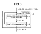
- FIG. 6 is a configuration diagram of the protection control device 9 according to the third embodiment of the present invention.
- the protection control device 9 in the present embodiment is different from the protection control device 9 illustrated in FIG. 2 in that the circuit-breaker switch-on requests D1 to Dn output from the protection control terminals 8 are input to the protection control device 9.
- FIG. 7 is a flowchart of the synchronism detection process performed by the synchronism indicator 92 according to the third embodiment of the present invention.
- the synchronism indicator 92 determines whether all the simulated bus voltages V1 and V2 have been received from the simulated-bus-voltage selecting unit 91. If all the simulated bus voltages V1 and V2 have not been received (No in Step S71), the synchronism indicator 92 continues the simulated-bus-voltage receiving process until the simulated bus voltages V1 and V2 are received. When the simulated bus voltages V1 and V2 have been received (Yes in Step S71), the synchronism indicator 92 performs the process in Step S72.
- Step S72 the synchronism indicator 92 determines whether any of the circuit-breaker switch-on requests D1 to Dn has been received. If none of the circuit-breaker switch-on requests D1 to Dn has been received (No in Step S72), the synchronism indicator 92 ends the synchronism detection process. When any of the circuit-breaker switch-on requests D1 to Dn is received (Yes in Step S72), the synchronism indicator 92 performs the process in Step S73.
- Step S73 the synchronism indicator 92 checks whether the voltage data VL of the line 3 corresponding to the protection control terminal 8 that is a transmission source of a corresponding one of the circuit-breaker switch-on requests D1 to Dn is normal and checks whether the CB arranged on the line 3 is in an open state. If the voltage data VL is abnormal and/or the CB is in a closed state (No in Step S73), the synchronism indicator 92 ends the synchronism detection process. If the voltage data VL is normal and the CB is in an open state (Yes in Step S73), the synchronism indicator 92 performs the process in Step S74.
- Step S74 the synchronism indicator 92 checks whether the disconnector (LS5) of the line 3 corresponding to the protection control terminal 8 that is a transmission source of a corresponding one of the circuit-breaker switch-on requests D1 to Dn is in a closed state. If the LS5 is in a closed state (Yes in Step S74), the synchronism indicator 92 performs the process in Step S75 and, if the LS5 is in an open state (No in Step S74), the synchronism indicator 92 performs the process in Step S76.
- Step S75 the synchronism indicator 92 performs the synchronism detection on the simulated bus voltage V1 and the voltage data VL. If the synchronism indicator 92 determines that the simulated bus voltage V1 and the voltage data VL are in a synchronized state, the synchronism indicator 92 outputs a corresponding one of the pieces of the information C1 to Cn to the protection control terminal 8 that is a transmission source of a corresponding one of the circuit-breaker switch-on requests D1 to Dn and ends the synchronism detection process.
- Step S76 the synchronism indicator 92 checks whether the disconnector (LS6) of the line 3 corresponding to the protection control terminal 8 that is a transmission source of a corresponding one of the circuit-breaker switch-on requests D1 to Dn is in a closed state. If the LS6 is in a closed state (Yes in Step S76), the synchronism indicator 92 performs the process in Step S77. If the LS6 is in an open state (No in Step S76), the synchronism indicator 92 ends the synchronism detection process.
- the disconnector (LS6) of the line 3 corresponding to the protection control terminal 8 that is a transmission source of a corresponding one of the circuit-breaker switch-on requests D1 to Dn is in a closed state. If the LS6 is in a closed state (Yes in Step S76), the synchronism indicator 92 performs the process in Step S77. If the LS6 is in an open state (No in Step S76), the synchronism indicator 92 ends the synchronism detection process
- Step S77 the synchronism indicator 92 performs the synchronism detection on the simulated bus voltage V2 and the voltage data VL. If the synchronism indicator 92 determines that the simulated bus voltage V2 and the voltage data VL are in a synchronized state, the synchronism indicator 92 outputs a corresponding one of the pieces of the information C1 to Cn to the protection control terminal 8 that is a transmission source of a corresponding one of the circuit-breaker switch-on requests D1 to Dn and ends the synchronism detection process.
- the open/closed state of the disconnector 5 and the disconnector 6 is checked in sequence starting with the disconnector 5 and then the disconnector 6; however, the open/closed state may be checked in sequence starting with the disconnector 6 and then the disconnector 5.
- the protection control device 9 is configured such that when the synchronism indicator 92 receives the simulated bus voltages V1 and V2, if the circuit breaker 4 arranged on the line 3 corresponding to the protection control terminal 8 that is a transmission source of the circuit-breaker switch-on request (D1 to Dn) is in an open state and the disconnectors 5 and 6 arranged on the line 3 are in a closed state, the synchronism indicator 92 performs the synchronism detection process and transmits a corresponding one of the pieces of the information C1 to Cn to the protection control terminal 8; therefore, the processing load of the protection control device 9 can be reduced compared with the case where the synchronism detection is performed on all the lines 3 as in the first embodiment and the amount of transmission of the information C1 to Cn transmitted to the protection control terminals 8 can be reduced compared with the first embodiment.
- the protection control device 9 in the third embodiment is preferable for a substation or the like in which the circuit breakers 4 are manually switched on instead of performing reclosing by using a protection relay.
- the protection control device in the second embodiment is configured to perform the simulated-bus-voltage selection process on a first-come-first-served basis and the protection control device in the third embodiment is configured to perform the synchronism detection process by using the circuit-breaker switch-on requests D.
- the protection control device 9 according to the embodiment of the present invention is not limited to this and may be configured such that the simulated-bus-voltage selection process in the second embodiment and the synchronism detection process in the third embodiment are combined. With such a configuration, it is possible to obtain the effects of the second and third embodiments.
- the protection control device 9 is the digital protection control device 9 that acquires a bus voltage by using data from the protection control terminals 8 that convert the voltages detected by the voltage transformers 7 arranged on the lines 3, the states of the circuit breakers 4 arranged on the lines 3, and the states of the disconnectors 5 and 6 arranged on the lines 3 into digital data, and that includes the simulated-bus-voltage selecting unit 91 that selects voltage data (VL) as the simulated bus voltages V1 and V2 that are simulated values of bus voltages on the basis of the voltage data (VL) related to a voltage, the data (CB) related to the states of the circuit breakers 4, and the data (LS) related to the states of the disconnectors 5 and 6 and the synchronism indicator 92 that performs the detection process of whether the voltage data (VL) and each of the simulated bus voltages V1 and V2 are in a synchronized state and outputs the information C1 to Cn indicating that the voltage data (VL
- the process flows according to the first to third embodiments can be applied also to the substation configuration, such as a 1-1/2CB bus system.
- the protection control device 9 according to the first to third embodiments of the present invention is applied to a double bus; however, the present invention can be applied also to a case of a single bus.
- the protection control device 9 according to the first to third embodiments is one example of the content of the present invention and it is obvious that it can be combined with other publicly known technologies and the configuration can be changed, for example, by omitting a part thereof without departing from the scope of the present invention.
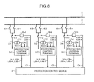
- FIG. 8 is a first diagram for explaining another example of an application of the protection control device according to the first to third embodiments of the present invention.
- the protection control terminals 8 illustrated in FIG. 1 accept switch-on instructions upon receiving the information C1 to Cn and switch on the circuit breakers 4 when the switch-on condition is satisfied; however, IEDs (Intelligent Electric Devices) 10-1 to 10-n illustrated in FIG. 8 receive the information C1 to Cn from the protection control device 9 instead of the protection control terminals 8 and switch on the circuit breakers 4 when the switch-on condition is satisfied.
- IEDs Intelligent Electric Devices
- FIG. 9 is a second diagram for explaining another example of an application of the protection control device according to the first to third embodiments of the present invention.
- the difference between FIG. 8 and FIG. 9 is in the communication configuration between the protection control terminals 8 and the protection control device 9.
- data output from the protection control terminals 8 is captured by the protection control device 9 via one network.
- the configuration is such that the information C1 to Cn generated based on the data transmitted from the protection control terminals 8 are input to the IEDs 10-1 to 10-n, the effects similar to those in the first to third embodiments can be obtained.
- the present invention can be applied mainly to a merging unit of a protection relay and is particularly useful as an invention that can continue protection even when the sampling frequency is discontinued.
Landscapes
- Emergency Protection Circuit Devices (AREA)
Abstract
Description
- The present invention relates to a digital protection control device that acquires a bus voltage and operates even when a voltage transformer for measuring a bus voltage is not arranged on a substation bus or even in a state where a voltage transformer for measuring a bus voltage cannot be used.
- In order to reduce costs, instead of using a voltage transformer for acquiring a bus voltage, conventional protection control devices, for example, capture secondary outputs of voltage transformers arranged on the lines branching off from the bus and compare these outputs in an analog manner on the basis the circuit breaker conditions and the disconnector conditions on the lines (connecting the secondary outputs of the voltage transformers with each other), thereby selecting and acquiring a bus voltage (for example,
Non Patent Literature 1 described below). - Non Patent Literature 1: "Supply and Installation Substation Automation Systems PM2-0008-WBX", Metropolitan Electricity Authority (Klongmahasawad (KMS) Substation explanatory diagram)
- However, in a digital protection control system that consists of protection control terminals that convert secondary outputs of voltage transformers into digital outputs and a protection control device that performs a protection calculation by using the digital outputs from the protection control terminals, digital data is output from the protection control terminals; therefore, it is difficult to use a method of acquiring a bus voltage by simply comparing the secondary outputs of the voltage transformers, which is used in an analog system.
- The present invention has been achieved in view of the above and an object of the present invention is to obtain a digital protection control device capable of acquiring a bus voltage by using digital data output from protection control terminals.
- In order to solve the above problems and achieve the object, the present invention is a digital protection control device that acquires a bus voltage by using data from a protection control terminal that converts a voltage detected by a voltage transformer arranged on a plurality of lines, a state of a circuit breaker arranged on each of the lines, and a state of a disconnector arranged on each of the lines into digital data, including a simulated-bus-voltage selecting unit that, on a basis of voltage data related to the voltage, data related to the state of the circuit breaker, and data related to the state of the disconnector, selects the voltage data as a simulated bus voltage that is a simulated value of the bus voltage; and a synchronism indicator that performs a detection process of whether the voltage data and the simulated bus voltage selected by the simulated-bus-voltage selecting unit are in a synchronized state and outputs information indicating a synchronized state to the protection control terminal.
- According to the present invention, an effect is obtained where a bus voltage can be acquired by using digital data output from protection control terminals.
-
-
FIG. 1 is a circuit configuration diagram of the periphery of circuit breakers focusing on a protection control device according to first to third embodiments of the present invention. -
FIG. 2 is a configuration diagram of the protection control device illustrated inFIG. 1 . -
FIG. 3 is a flowchart of a simulated-bus-voltage selection process performed by a simulated-bus-voltage selecting unit according to the first embodiment of the present invention. -
FIG. 4 is a flowchart of a synchronism detection process performed by a synchronism indicator according to the first embodiment of the present invention. -
FIG. 5 is a flowchart of the simulated-bus-voltage selection process performed by a simulated-bus-voltage selecting unit according to a second embodiment of the present invention. -
FIG. 6 is a configuration diagram of a protection control device according to a third embodiment of the present invention. -
FIG. 7 is a flowchart of the synchronism detection process performed by a synchronism indicator according to the third embodiment of the present invention. -
FIG. 8 is a first diagram for explaining another example of an application of the protection control device according to the first to third embodiments of the present invention. -
FIG. 9 is a second diagram for explaining another example of an application of the protection control device according to the first to third embodiments of the present invention. - Exemplary embodiments of a protection control device according to the present invention will be explained below in detail with reference to the drawings. This invention is not limited to the embodiments.
-
FIG. 1 is a circuit configuration diagram of the periphery of circuit breakers focusing on a protection control device according to first to third embodiments of the present invention.FIG. 2 is a configuration diagram of aprotection control device 9 illustrated inFIG. 1 . In the following explanation, when an explanation is made of a point that is common among all of protection control terminals 8-1 to 8-n, these are generically referred to as protection control terminal(s) 8. Moreover, lines 3-1 to 3-n are referred to as line(s) 3, circuit breakers 4-1 to 4-n are referred to as circuit breaker(s) 4, disconnectors 5-1 to 5-n are referred to as disconnector(s) 5, disconnectors 6-1 to 6-n are referred to as disconnector(s) 6, and voltage transformers 7-1 to 7-n are referred to as voltage transformer(s) 7. - The digital protection control system illustrated in
FIG. 1 is configured to include, as main components, theprotection control device 9 and theprotection control terminals 8. Thedisconnector 5 and the circuit breaker (CB) 4 are arranged in sequence, starting from abus 1 side, between thebus 1 and theline 3 illustrated inFIG. 1 . Thedisconnector 6 and thecircuit breaker 4 are arranged in sequence, starting from abus 2 side, between thebus 2 and theline 3. Thedisconnector 5 is arranged between thebus 1 and thecircuit breaker 4 and thedisconnector 6 is arranged between thebus 2 and thecircuit breaker 4. Thevoltage transformer 7 for acquiring a line voltage is connected to theline 3. - In a case where the
circuit breakers 4 receive switch-on instructions from the outside, when line-voltage data VL1 to VLn, first disconnector data LS5-1 to LS5-n indicating the states of thedisconnectors 5, disconnector data LS6-1 to LS6-n indicating the states of thedisconnectors 6, and circuit breaker data CB1 to CBn indicating the states of thecircuit breakers 4 satisfy a certain condition (which will be described later), thecircuit breakers 4 are switched on (enter an "on" state). In the following explanation, the line-voltage data VL1 to VLn are referred to as line-voltage data VL, the first disconnector data LS5-1 to LS5-n are referred to as first disconnector data LS5, the disconnector data LS6-1 to LS6-n are referred to as disconnector data LS6, and the circuit breaker data CB1 to CBn are referred to as circuit breaker data CB. - The
protection control terminals 8 receive the line-voltage data VL1 to VLn detected by thevoltage transformers 7, the first disconnector data LS5, the disconnector data LS6, and the circuit breaker data CB and then output the voltage data VL on the basis of these pieces of data. -
FIG. 2 is a configuration diagram illustrating theprotection control device 9 according to the first embodiment of the present invention. Theprotection control device 9 is configured to include, as main components, a simulated-bus-voltage selecting unit 91 and asynchronism indicator 92. - The simulated-bus-voltage selecting unit 91 is used to select normal values (values correctly indicating the voltages of the
buses 1 and 2) from the voltage data VL output from theprotection control terminals 8. The priority of thelines 3 is preset in the simulated-bus-voltage selecting unit 91 according to the first embodiment and the simulated-bus-voltage selecting unit 91 selects a simulated bus voltage V1 or a simulated bus voltage V2 from the voltage data VL on the basis of the data from theprotection control terminals 8 and the priority and then outputs the selected simulated bus voltages V1 and V2 to thesynchronism indicator 92. The priority is information necessary for determining the simulated bus voltages V1 and V2 from the voltage data VL. For example, when fivelines 3 are connected to thebus 1, the priority is used for determining which of thelines 3 is selected as a detection source of the simulated bus voltage V1 from among these five lines. The priority is, for example, set according to the installation time of each of thelines 3 and is set such that theline 3 whose installation time is earlier has a higher priority. However, the method of setting the priority is not limited thereto and the priority may be set by using any other method. - The
synchronism indicator 92 receives the voltage data VL and determines, on the basis of the data, whether the simulated bus voltage V1 and the voltage data VL are in a synchronized state satisfying a certain relationship (whether no problem occurs even if thecircuit breaker 4 is switched on again) and determines whether the simulated bus voltage V2 and the voltage data VL are in a synchronized state satisfying a certain relationship. This synchronism determination is performed such that, for example, when the difference in each of the frequency, phase, and voltage value between the simulated bus voltage V1 (V2) and the voltage data VL is within a defined range, it is determined that they are in a state (synchronized state) satisfying a certain relationship, and information C1 to Cn indicating that they are in the synchronized state is transmitted to theprotection control terminals 8 from thesynchronism indicator 92. After receiving switch-on instructions from the outside, theprotection control terminals 8 that have received the information C1 to Cn accept the switch-on instructions when theprotection control terminals 8 receive the information C1 to Cn from thesynchronism indicator 92, and switch on thecircuit breakers 4 corresponding to the switch-on instructions. - The operation of the
protection control device 9 according to the first embodiment will be explained below.FIG. 3 is a flowchart of a simulated-bus-voltage selection process performed by the simulated-bus-voltage selecting unit 91 according to the first embodiment of the present invention. The simulated-bus-voltage selecting unit 91 determines whether all the pieces of the voltage data VL have been received. If all the pieces of the voltage data VL have not been received (No in Step S10), the simulated-bus-voltage selecting unit 91 continues the receiving process until all the pieces of the voltage data VL are received. When all the pieces of the voltage data VL have been received (Yes in Step S10), the simulated-bus-voltage selecting unit 91 performs the process in Step S11. - In Step S11, the simulated-bus-voltage selecting unit 91 sets a variable i, indicating a line to be processed, to "1", sets the total number of lines N in a priority Pri1 of the
line 3 corresponding to the simulated bus voltage V1 that is currently set as the voltage of thebus 1, sets the total number of lines N in a priority Pri2 of thelines 3 corresponding to the simulated bus voltage V2 that is currently set as the voltage of thebus 2, sets "0" as the simulated bus voltage V1, and sets "0" as the simulated bus voltage V2. - Next, the simulated-bus-voltage selecting unit 91 determines whether the variable i is equal to or less than the total number of lines N. If the variable i exceeds the total number of lines N (No in Step S12), the simulated-bus-voltage selecting unit 91 ends the simulated-bus-voltage selection process. If the variable i is equal to or less than the total number of lines N (Yes in Step S12), the simulated-bus-voltage selecting unit 91 performs the process in Step S13.
- In Step S13, if the voltage data VL(i) is abnormal and/or the CB(i) is in an open state (No in Step S13), the simulated-bus-voltage selecting unit 91 performs the process in Step S20. If the voltage data VL(i) is normal and the CB(i) is in a closed state (Yes in Step S13), the simulated-bus-voltage selecting unit 91 performs the process in Step S14.
- In Step S14, the simulated-bus-voltage selecting unit 91 checks whether the disconnector 5 (LS5(i)) of the
line 3 corresponding to the value of the variable i is in a closed state. If the LS5(i) is in an open state (No in Step S14), the simulated-bus-voltage selecting unit 91 performs the process in Step S17 and, if the LS5(i) is in a closed state (Yes in Step S14), the simulated-bus-voltage selecting unit 91 performs the process in Step S15. - In Step S15, the simulated-bus-voltage selecting unit 91 compares the priority Pri(i) of the
line 3 corresponding to the variable i with the value of the Pri1. If the value of the priority Pri(i) is larger than the value of the Pri1 (No in Step S15), the simulated-bus-voltage selecting unit 91 determines that the priority Pri(i) is low and performs the process in Step S17 and, if the value of the priority Pri(i) is equal to or lower than the value of the Pri1 (Yes in Step S15), the simulated-bus-voltage selecting unit 91 determines that the priority Pri(i) is high and performs the process in Step S16. - In Step S16, the simulated-bus-voltage selecting unit 91 sets the priority Pri(i) to the priority Pri1 and sets the voltage data VL(i) as the simulated bus voltage V1. In Step S17, the simulated-bus-voltage selecting unit 91 checks whether the disconnector (LS6(i)) of the
line 3 corresponding to the value of the variable i is in a closed state. If the LS6(i) is in an open state (No in Step S17), the simulated-bus-voltage selecting unit 91 performs the process in Step S20 and, if the LS6(i) is in a closed state (Yes in Step S17), the simulated-bus-voltage selecting unit 91 performs the process in Step S18. - In Step S18, the simulated-bus-voltage selecting unit 91 compares the priority Pri(i) with the value of the Pri2. If the value of the priority Pri(i) is larger than the value of the Pri2 (No in Step S18), the simulated-bus-voltage selecting unit 91 determines that the priority Pri(i) is low and performs the process in Step S20 and, if the value of the priority Pri(i) is equal to or lower than the value of the Pri2 (Yes in Step S18), the simulated-bus-voltage selecting unit 91 determines that the priority Pri(i) is high and performs the process in Step S19.
- In Step S19, the simulated-bus-voltage selecting unit 91 sets the priority Pri(i) to the priority Pri2 and sets the voltage data VL(i) as the simulated bus voltage V2. Furthermore, in Step S20, the simulated-bus-voltage selecting unit 91 increments the variable i and performs the process in Step S12 again. Then, the simulated bus voltages V1 and V2 selected by the simulated-bus-voltage selecting unit 91 are transmitted to the
synchronism indicator 92. - In the flow in
FIG. 3 , the open/closed state of thedisconnector 5 and thedisconnector 6 is checked in sequence starting with thedisconnector 5 and then thedisconnector 6; however, the open/closed state may be checked in sequence starting with thedisconnector 6 and then thedisconnector 5. Moreover, the operation of the simulated-bus-voltage selecting unit 91 is not limited to that illustrated in the flow inFIG. 3 and, for example, it is possible to use a method of performing the operation on the basis of the priority orders (priority lines 3. -
FIG. 4 is a flowchart of a synchronism detection process performed by thesynchronism indicator 92 according to the first embodiment of the present invention. Thesynchronism indicator 92 determines whether the simulated bus voltages V1 and V2 have been received from the simulated-bus-voltage selecting unit 91. If the simulated bus voltages V1 and V2 have not been received (No in Step S51), thesynchronism indicator 92 continues the simulated-bus-voltage receiving process until the simulated bus voltages V1 and V2 are received. When the simulated bus voltages V1 and V2 have been received (Yes in Step S51), thesynchronism indicator 92 performs the process in Step S52. - In Step S52, the
synchronism indicator 92 sets the variable i, indicating a line to be processed, to "1". Moreover, in Step S53, thesynchronism indicator 92 determines whether the variable i is equal to or less than the total number of lines N. If the variable i exceeds the total number of lines N (No in Step S53), thesynchronism indicator 92 ends the synchronism detection process. If the variable i is equal to or less than the total number of lines N (Yes in Step S53), thesynchronism indicator 92 performs the process in Step S54. - In Step S54, the
synchronism indicator 92 checks that the voltage data VL(i) of theline 3 corresponding to the value of the variable i is normal and checks whether the CB(i) arranged on theline 3 corresponding to the value of the variable i is in an open state. If the voltage data VL(i) is abnormal and/or the CB(i) is in a closed state (No in Step S54), thesynchronism indicator 92 performs the process in Step S59. If the voltage data VL(i) is normal and the CB(i) is in an open state (Yes in Step S54), thesynchronism indicator 92 performs the process in Step S55. - In Step S55, the
synchronism indicator 92 checks whether the disconnector (LS5(i)) of theline 3 corresponding to the value of the variable i is in a closed state. If the LS5(i) is in a closed state (Yes in Step S55), thesynchronism indicator 92 performs the process in Step S56 and, if the LS5(i) is in an open state (No in Step S56), thesynchronism indicator 92 performs the process in Step S57. - In Step S56, the
synchronism indicator 92 performs a synchronism detection on the simulated bus voltage V1 and the voltage data VL(i). Specifically, when the difference in each of the frequency, phase, and voltage value between the simulated bus voltage V1 and the voltage data VL is within a defined range, thesynchronism indicator 92 determines that the simulated bus voltage V1 and the voltage data VL(i) are in a synchronized state and outputs a corresponding one of the pieces of the information C1 to Cn to theprotection control terminal 8, and then performs the process in Step S59. - In Step S57, the
synchronism indicator 92 checks whether the disconnector (LS6(i)) of theline 3 corresponding to the value of the variable i is in a closed state. If the LS6(i) is in a closed state (Yes in Step S57), thesynchronism indicator 92 performs the process in Step S58 and, if the LS6(i) is in an open state (No in Step S57), thesynchronism indicator 92 performs the process in Step S59. - In Step S58, the
synchronism indicator 92 performs the synchronism detection on the simulated bus voltage V2 and the voltage data VL(i). Specifically, when the difference in each of the frequency, phase, and voltage value between the simulated bus voltage V2 and the voltage data VL is within a defined range, thesynchronism indicator 92 determines that the simulated bus voltage V2 and the voltage data VL(i) are in a synchronized state and outputs a corresponding one of the pieces of the information C1 to Cn to theprotection control terminal 8, and then performs the process in Step S59. Finally, in Step S59, thesynchronism indicator 92 increments the variable i and performs the process in Step S53 again. In the flow inFIG. 4 , the open/closed state of thedisconnector 5 and thedisconnector 6 is checked in sequence starting with thedisconnector 5 and then thedisconnector 6; however, the open/closed state may be checked in sequence starting with thedisconnector 6 and then thedisconnector 5. - As described above, the priority of the
lines 3 is set in the simulated-bus-voltage selecting unit 91 according to the first embodiment. When thecircuit breaker 4 and the disconnectors 5 and 6 are in a closed state, the simulated-bus-voltage selecting unit 91 selects the simulated bus voltages V1 and V2 corresponding to theline 3 having the highest priority. Moreover, upon receiving the simulated bus voltages V1 and V2, thesynchronism indicator 92 according to the first embodiment performs the synchronism detection process when thecircuit breaker 4 is in an open state and the disconnectors 5 and 6 are in a closed state. Therefore, when a voltage transformer for measuring bus voltages is not arranged on thebuses protection control terminals 8 that convert the line voltages VL1 to VLn into digital outputs and theprotection control device 9 that performs a protection calculation by using the digital outputs from theprotection control terminals 8. Accordingly, it is possible to eliminate the voltage transformer for measuring the bus voltages of thebuses protection control device 9, the calculation load of eachprotection control terminal 8 can be reduced, for example, compared with a case where eachprotection control terminal 8 performs the synchronism detection process. - The
protection control device 9 in the first embodiment is configured to perform the simulated-bus-voltage selection process by using the priority after all the pieces of the voltage data VL have been received. Theprotection control device 9 according to a second embodiment is configured to perform the simulated-bus-voltage selection process by using the voltage data VL that arrives first from among the data transmitted from theprotection control terminals 8. The synchronism detection process is similar to that in the first embodiment and therefore an explanation thereof is omitted. Hereinafter, components identical to those of the first embodiment are denoted by the same reference signs and explanations thereof will be omitted, and only different points are explained. -
FIG. 5 is a flowchart of the simulated-bus-voltage selection process performed by the simulated-bus-voltage selecting unit 91 according to the second embodiment of the present invention. The simulated-bus-voltage selecting unit 91 sets the simulated bus voltage V1 that is currently set as a voltage of thebus 1 to "0", sets the simulated bus voltage V2 that is currently set as a voltage of thebus 2 to "0", sets aFlag 1 indicating whether the simulated bus voltage V1 has already been selected to "0" (unselected), and sets aFlag 2 indicating whether the simulated bus voltage V2 has already been selected to "0" (Step S31). - In Step S32, the simulated-bus-voltage selecting unit 91 determines whether any piece of the voltage data VL from the
protection control terminals 8 has been received. If no voltage data VL has been received (No in Step S32), the simulated-bus-voltage selecting unit 91 continues a receiving process until any piece of the voltage data VL is received. When any piece of the voltage data VL is received (Yes in Step S32), the simulated-bus-voltage selecting unit 91 performs the process in Step S33. - In Step S33, the simulated-bus-voltage selecting unit 91 stores the voltage data VL, the circuit breaker data CB, the first disconnector data LS5, and the second disconnector data LS6.
- In Step S34, the simulated-bus-voltage selecting unit 91 checks that the voltage data VL is normal and checks whether the circuit breaker data CB is in a closed state. If the voltage data VL is abnormal and/or the circuit breaker data CB is in an open state (No in Step S34), the simulated-bus-voltage selecting unit 91 performs the process in Step S41. If the voltage data VL(i) is normal and the circuit breaker data CB is in a closed state (Yes in Step S34), the simulated-bus-voltage selecting unit 91 performs the process in Step S35.
- In Step S35, the simulated-bus-voltage selecting unit 91 determines whether the voltage data VL has already been selected. If the
Flag 1 is "1" (No in Step S35), the simulated-bus-voltage selecting unit 91 performs the process in Step S38 and, if theFlag 1 is "0" (Yes in Step S35), the simulated-bus-voltage selecting unit 91 performs the process in Step S36. - In Step S36, the simulated-bus-voltage selecting unit 91 checks whether the disconnector (LS5) is in a closed state. If the LS5 is in an open state (No in Step S36), the simulated-bus-voltage selecting unit 91 performs the process in Step S38 and, if the LS5 is in a closed state (Yes in Step S36), the simulated-bus-voltage selecting unit 91 performs the process in Step S37.
- In Step S37, the simulated-bus-voltage selecting unit 91 sets the voltage data VL of the
line 3 received in Step S32 as the simulated bus voltage V1 and sets theFlag 1 to "1" (selected). - In Step S38, the simulated-bus-voltage selecting unit 91 determines whether the voltage data VL has already been selected. If the
Flag 2 is "1" (No in Step S38), the simulated-bus-voltage selecting unit 91 performs the process in Step S41 and, if theFlag 2 is "0" (Yes in Step S38), the simulated-bus-voltage selecting unit 91 performs the process in Step S39. - In Step S39, the simulated-bus-voltage selecting unit 91 checks whether the disconnector (LS6) is in a closed state. If the LS6 is in an open state (No in Step S39), the simulated-bus-voltage selecting unit 91 performs the process in Step S41. If the LS6 is in a closed state (Yes in Step S39), the simulated-bus-voltage selecting unit 91 performs the process in Step S40.
- In Step S40, the simulated-bus-voltage selecting unit 91 sets the voltage data VL of the
line 3 received in Step S32 as the simulated bus voltage V2 and sets theFlag 2 to "1" (selected). - In Step S41, the simulated-bus-voltage selecting unit 91 determines whether the values of the
Flag 1 and theFlag 2 are both "1". If either or both of theFlag 1 and theFlag 2 has a value of "0" (No in Step S41), the simulated-bus-voltage selecting unit 91 performs the process in Step S32. If the values of theFlag 1 and theFlag 2 are both "1" (Yes in Step S41), the simulated-bus-voltage selecting unit 91 ends the process. - In the flow in
FIG. 5 , the states of theFlags disconnector 5 or thedisconnector 6 is checked; however, the open/closed state of thedisconnector 5 or thedisconnector 6 may be checked after the states of theFlags - As explained above, the
protection control device 9 according to the second embodiment is such that the simulated-bus-voltage selecting unit determines whether thecircuit breaker 4 and the disconnectors 5 and 6 are in a closed state in order of the arrival of the voltage data VL from theprotection control terminals 8 and, if thecircuit breaker 4 and the disconnectors 5 and 6 are in a closed state, the simulated-bus-voltage selecting unit selects the simulated bus voltages V1 and V2. Therefore, the bus voltages can be selected earlier than in the first embodiment and thus the processing load of theprotection control device 9 itself can be reduced. - The
protection control device 9 in the first embodiment is configured to perform the synchronism detection process on all thelines 3 by changing the variable i. Theprotection control device 9 in a third embodiment is configured to, after performing the simulated-bus-voltage selection process similar to that in the first embodiment, perform the synchronism detection process only on theline 3 corresponding to theprotection control terminal 8 that is a transmission source of a corresponding one of circuit-breaker switch-on requests D1 to Dn and transmit a corresponding one of the pieces of the information C1 to Cn to theprotection control terminal 8. The circuit-breaker switch-on requests D1 to Dn are, for example, data that is transmitted to theprotection control device 9 from the protection control terminal 8-1 in response to a manual switch-on request from the operator when the operator switches on the circuit breaker 4-1 again. Hereinafter, components identical to those of the first embodiment are denoted by the same reference signs and explanations thereof will be omitted, and only different points are explained. -
FIG. 6 is a configuration diagram of theprotection control device 9 according to the third embodiment of the present invention. Theprotection control device 9 in the present embodiment is different from theprotection control device 9 illustrated inFIG. 2 in that the circuit-breaker switch-on requests D1 to Dn output from theprotection control terminals 8 are input to theprotection control device 9. -
FIG. 7 is a flowchart of the synchronism detection process performed by thesynchronism indicator 92 according to the third embodiment of the present invention. Thesynchronism indicator 92 determines whether all the simulated bus voltages V1 and V2 have been received from the simulated-bus-voltage selecting unit 91. If all the simulated bus voltages V1 and V2 have not been received (No in Step S71), thesynchronism indicator 92 continues the simulated-bus-voltage receiving process until the simulated bus voltages V1 and V2 are received. When the simulated bus voltages V1 and V2 have been received (Yes in Step S71), thesynchronism indicator 92 performs the process in Step S72. - In Step S72, the
synchronism indicator 92 determines whether any of the circuit-breaker switch-on requests D1 to Dn has been received. If none of the circuit-breaker switch-on requests D1 to Dn has been received (No in Step S72), thesynchronism indicator 92 ends the synchronism detection process. When any of the circuit-breaker switch-on requests D1 to Dn is received (Yes in Step S72), thesynchronism indicator 92 performs the process in Step S73. - In Step S73, the
synchronism indicator 92 checks whether the voltage data VL of theline 3 corresponding to theprotection control terminal 8 that is a transmission source of a corresponding one of the circuit-breaker switch-on requests D1 to Dn is normal and checks whether the CB arranged on theline 3 is in an open state. If the voltage data VL is abnormal and/or the CB is in a closed state (No in Step S73), thesynchronism indicator 92 ends the synchronism detection process. If the voltage data VL is normal and the CB is in an open state (Yes in Step S73), thesynchronism indicator 92 performs the process in Step S74. - In Step S74, the
synchronism indicator 92 checks whether the disconnector (LS5) of theline 3 corresponding to theprotection control terminal 8 that is a transmission source of a corresponding one of the circuit-breaker switch-on requests D1 to Dn is in a closed state. If the LS5 is in a closed state (Yes in Step S74), thesynchronism indicator 92 performs the process in Step S75 and, if the LS5 is in an open state (No in Step S74), thesynchronism indicator 92 performs the process in Step S76. - In Step S75, the
synchronism indicator 92 performs the synchronism detection on the simulated bus voltage V1 and the voltage data VL. If thesynchronism indicator 92 determines that the simulated bus voltage V1 and the voltage data VL are in a synchronized state, thesynchronism indicator 92 outputs a corresponding one of the pieces of the information C1 to Cn to theprotection control terminal 8 that is a transmission source of a corresponding one of the circuit-breaker switch-on requests D1 to Dn and ends the synchronism detection process. - In Step S76, the
synchronism indicator 92 checks whether the disconnector (LS6) of theline 3 corresponding to theprotection control terminal 8 that is a transmission source of a corresponding one of the circuit-breaker switch-on requests D1 to Dn is in a closed state. If the LS6 is in a closed state (Yes in Step S76), thesynchronism indicator 92 performs the process in Step S77. If the LS6 is in an open state (No in Step S76), thesynchronism indicator 92 ends the synchronism detection process. - In Step S77, the
synchronism indicator 92 performs the synchronism detection on the simulated bus voltage V2 and the voltage data VL. If thesynchronism indicator 92 determines that the simulated bus voltage V2 and the voltage data VL are in a synchronized state, thesynchronism indicator 92 outputs a corresponding one of the pieces of the information C1 to Cn to theprotection control terminal 8 that is a transmission source of a corresponding one of the circuit-breaker switch-on requests D1 to Dn and ends the synchronism detection process. In the flow inFIG. 7 , the open/closed state of thedisconnector 5 and thedisconnector 6 is checked in sequence starting with thedisconnector 5 and then thedisconnector 6; however, the open/closed state may be checked in sequence starting with thedisconnector 6 and then thedisconnector 5. - As explained above, the
protection control device 9 according to the third embodiment is configured such that when thesynchronism indicator 92 receives the simulated bus voltages V1 and V2, if thecircuit breaker 4 arranged on theline 3 corresponding to theprotection control terminal 8 that is a transmission source of the circuit-breaker switch-on request (D1 to Dn) is in an open state and the disconnectors 5 and 6 arranged on theline 3 are in a closed state, thesynchronism indicator 92 performs the synchronism detection process and transmits a corresponding one of the pieces of the information C1 to Cn to theprotection control terminal 8; therefore, the processing load of theprotection control device 9 can be reduced compared with the case where the synchronism detection is performed on all thelines 3 as in the first embodiment and the amount of transmission of the information C1 to Cn transmitted to theprotection control terminals 8 can be reduced compared with the first embodiment. Thus, it is possible to reduce the load on the network provided between theprotection control terminals 8 and theprotection control device 9. Particularly, theprotection control device 9 in the third embodiment is preferable for a substation or the like in which thecircuit breakers 4 are manually switched on instead of performing reclosing by using a protection relay. - In the above explanation, the protection control device in the second embodiment is configured to perform the simulated-bus-voltage selection process on a first-come-first-served basis and the protection control device in the third embodiment is configured to perform the synchronism detection process by using the circuit-breaker switch-on requests D. The
protection control device 9 according to the embodiment of the present invention is not limited to this and may be configured such that the simulated-bus-voltage selection process in the second embodiment and the synchronism detection process in the third embodiment are combined. With such a configuration, it is possible to obtain the effects of the second and third embodiments. - As explained above, the
protection control device 9 according to the first to third embodiments is the digitalprotection control device 9 that acquires a bus voltage by using data from theprotection control terminals 8 that convert the voltages detected by thevoltage transformers 7 arranged on thelines 3, the states of thecircuit breakers 4 arranged on thelines 3, and the states of thedisconnectors lines 3 into digital data, and that includes the simulated-bus-voltage selecting unit 91 that selects voltage data (VL) as the simulated bus voltages V1 and V2 that are simulated values of bus voltages on the basis of the voltage data (VL) related to a voltage, the data (CB) related to the states of thecircuit breakers 4, and the data (LS) related to the states of thedisconnectors synchronism indicator 92 that performs the detection process of whether the voltage data (VL) and each of the simulated bus voltages V1 and V2 are in a synchronized state and outputs the information C1 to Cn indicating that the voltage data (VL) and each of the simulated bus voltages V1 and V2 are in a synchronized state to theprotection control terminals 8. Therefore, it is possible to acquire a bus voltage by using digital data output from theprotection control terminals 8. - The process flows according to the first to third embodiments can be applied also to the substation configuration, such as a 1-1/2CB bus system. Moreover, in the above explanation, explanation is made of an example in which the
protection control device 9 according to the first to third embodiments of the present invention is applied to a double bus; however, the present invention can be applied also to a case of a single bus. Moreover, theprotection control device 9 according to the first to third embodiments is one example of the content of the present invention and it is obvious that it can be combined with other publicly known technologies and the configuration can be changed, for example, by omitting a part thereof without departing from the scope of the present invention. - The
protection control device 9 according to the first to third embodiments can be applied to the following configuration on the periphery of the circuit breakers.FIG. 8 is a first diagram for explaining another example of an application of the protection control device according to the first to third embodiments of the present invention. Theprotection control terminals 8 illustrated inFIG. 1 accept switch-on instructions upon receiving the information C1 to Cn and switch on thecircuit breakers 4 when the switch-on condition is satisfied; however, IEDs (Intelligent Electric Devices) 10-1 to 10-n illustrated inFIG. 8 receive the information C1 to Cn from theprotection control device 9 instead of theprotection control terminals 8 and switch on thecircuit breakers 4 when the switch-on condition is satisfied.FIG. 9 is a second diagram for explaining another example of an application of the protection control device according to the first to third embodiments of the present invention. The difference betweenFIG. 8 andFIG. 9 is in the communication configuration between theprotection control terminals 8 and theprotection control device 9. InFIG. 9 , data output from theprotection control terminals 8 is captured by theprotection control device 9 via one network. As described above, even when the configuration is such that the information C1 to Cn generated based on the data transmitted from theprotection control terminals 8 are input to the IEDs 10-1 to 10-n, the effects similar to those in the first to third embodiments can be obtained. - As described above, the present invention can be applied mainly to a merging unit of a protection relay and is particularly useful as an invention that can continue protection even when the sampling frequency is discontinued.
-
- 1, 2 bus
- 3-1, 3-2, 3-n line
- 4-1, 4-2, 4-n circuit breaker
- 5-1, 5-2, 5-n, 6-1, 6-2, 6-n disconnector
- 7-1, 7-2, 7-n voltage transformer
- 8-1, 8-2, 8-n protection control terminal
- 9 protection control device
- 10-1, 10-2, 10-n IED10-1, 10-2, 10-n
- C1 to Cn information
- CB1, CB2, CBn circuit breaker data
- D1, Dn circuit-breaker switch-on request
- LS5-1, LS5-2, LS5-n first disconnector data
- LS6-1, LS6-2, LS6-n second disconnector data
- V1, V2 simulated bus voltage
- VL1, VL2, VLn line-voltage data
Claims (6)
- A digital protection control device that acquires a bus voltage by using data from a protection control terminal that converts a voltage detected by a voltage transformer arranged on a plurality of lines, a state of a circuit breaker arranged on each of the lines, and a state of a disconnector arranged on each of the lines into digital data, the device comprising:a simulated-bus-voltage selecting unit that, on a basis of voltage data related to the voltage, data related to the state of the circuit breaker, and data related to the state of the disconnector, selects the voltage data as a simulated bus voltage that is a simulated value of the bus voltage; anda synchronism indicator that performs a detection process of whether the voltage data and the simulated bus voltage selected by the simulated-bus-voltage selecting unit are in a synchronized state and outputs information indicating a synchronized state to the protection control terminal.
- The protection control device according to claim 1, wherein
a priority of each of the lines is set in the simulated-bus-voltage selecting unit, and
the simulated-bus-voltage selecting unit selects a simulated bus voltage corresponding to a line whose priority is highest when the circuit breaker and the disconnector are in a closed state. - The protection control device according to claim 1, wherein in a case where a synchronism indicator has received a simulated bus voltage, when the circuit breaker is in an open state and the disconnector is in a closed state, the synchronism indicator performs the detection process.
- The protection control device according to claim 1, wherein the simulated-bus-voltage selecting unit determines whether the circuit breaker and the disconnector are in a closed state in order of arrival of the voltage data and, when the circuit breaker and the disconnector are in a closed state, selects a simulated bus voltage.
- The protection control device according to claim 1, wherein in a case where the synchronism indicator has received a simulated bus voltage, when the circuit breaker arranged on a line corresponding to a protection control terminal that is a transmission source of a circuit-breaker switch-on request is in an open state and the disconnector arranged on the line is in a closed state, the synchronism indicator performs the detection process.
- The protection control device according to claim 1, wherein
the simulated-bus-voltage selecting unit determines whether the circuit breaker and the disconnector are in a closed state in order of arrival of the voltage data and, when the circuit breaker and the disconnector are in a closed state, selects a simulated bus voltage, and
in a case where the synchronism indicator has received a simulated bus voltage, when the circuit breaker arranged on a line corresponding to a protection control terminal that is a transmission source of a circuit-breaker switch-on request is in an open state and the disconnector arranged on the line is in a closed state, the synchronism indicator performs the detection process.
Applications Claiming Priority (1)
| Application Number | Priority Date | Filing Date | Title |
|---|---|---|---|
| PCT/JP2011/073573 WO2013054419A1 (en) | 2011-10-13 | 2011-10-13 | Protective control device |
Publications (3)
| Publication Number | Publication Date |
|---|---|
| EP2768115A1 true EP2768115A1 (en) | 2014-08-20 |
| EP2768115A4 EP2768115A4 (en) | 2015-07-01 |
| EP2768115B1 EP2768115B1 (en) | 2021-09-15 |
Family
ID=48081496
Family Applications (1)
| Application Number | Title | Priority Date | Filing Date |
|---|---|---|---|
| EP11874093.5A Active EP2768115B1 (en) | 2011-10-13 | 2011-10-13 | Protective control device |
Country Status (3)
| Country | Link |
|---|---|
| EP (1) | EP2768115B1 (en) |
| JP (1) | JP5383931B2 (en) |
| WO (1) | WO2013054419A1 (en) |
Families Citing this family (1)
| Publication number | Priority date | Publication date | Assignee | Title |
|---|---|---|---|---|
| CN104931876B (en) * | 2015-06-25 | 2018-01-30 | 国网四川省电力公司映秀湾水力发电总厂 | Portable three-phase breaker simulation box |
Family Cites Families (5)
| Publication number | Priority date | Publication date | Assignee | Title |
|---|---|---|---|---|
| JPS6016117A (en) * | 1983-07-08 | 1985-01-26 | 株式会社日立製作所 | Simulating circuit of bus voltage |
| JPS6074917A (en) * | 1983-09-30 | 1985-04-27 | 株式会社東芝 | Information processor for protecting and controlling system of electric station |
| JPS61205234U (en) * | 1985-06-11 | 1986-12-24 | ||
| JP4128907B2 (en) * | 2003-05-22 | 2008-07-30 | 三菱電機株式会社 | Supervisory control system |
| JP5513771B2 (en) * | 2009-05-25 | 2014-06-04 | 株式会社東芝 | Synchronous verification system |
-
2011
- 2011-10-13 JP JP2012551825A patent/JP5383931B2/en active Active
- 2011-10-13 EP EP11874093.5A patent/EP2768115B1/en active Active
- 2011-10-13 WO PCT/JP2011/073573 patent/WO2013054419A1/en not_active Ceased
Also Published As
| Publication number | Publication date |
|---|---|
| EP2768115A4 (en) | 2015-07-01 |
| EP2768115B1 (en) | 2021-09-15 |
| WO2013054419A1 (en) | 2013-04-18 |
| JPWO2013054419A1 (en) | 2015-03-30 |
| JP5383931B2 (en) | 2014-01-08 |
Similar Documents
| Publication | Publication Date | Title |
|---|---|---|
| US10218167B2 (en) | Circuit breaker | |
| EP2335082B1 (en) | Method and apparatus for dynamic signal switching of a merging unit in an electrical power system | |
| WO2012139959A2 (en) | Remote control and operation of lv distribution networks | |
| US9966754B2 (en) | Circuit breaker | |
| CN101946385A (en) | Photovoltaic auxiliary generator junction box, photovoltaic generator junction box, photovoltaic inverter for photovoltaic equipment, and photovoltaic equipment | |
| CN104917160B (en) | A kind of distributed feed line automatization system permissive type fault handling method based on FTU | |
| WO2011134851A1 (en) | Protection of power lines | |
| JP2010161865A (en) | System and method for protecting ground of distribution system and program | |
| US8817444B2 (en) | Control arrangement | |
| EP2768115B1 (en) | Protective control device | |
| CN103503317B (en) | There is at least three and monitor base site controller on the ripple of input | |
| US10916930B2 (en) | Electrical power systems | |
| US20170373486A1 (en) | Phase control device | |
| Zhao et al. | Advanced bus transfer and load shedding applications with IEC61850 | |
| US11079436B2 (en) | Multiple merging unit testing system | |
| US11121536B2 (en) | Digital input electric power system panel meter | |
| CN116114132B (en) | Power distribution device | |
| Brunner | The impact of IEC 61850 on protection | |
| Boteza et al. | Automatic transfer switch using IEC 61850 protocol in smart grids | |
| GB2521143A (en) | An improved ring main unit | |
| Gajic et al. | Using IEC 61850 analogue goose messages for OLTC control of parallel transformers | |
| Cornell | Philosophy for operation of distribution system automation schemes: ACTEW's approach | |
| JP2004166353A (en) | Power distribution controller |
Legal Events
| Date | Code | Title | Description |
|---|---|---|---|
| PUAI | Public reference made under article 153(3) epc to a published international application that has entered the european phase |
Free format text: ORIGINAL CODE: 0009012 |
|
| 17P | Request for examination filed |
Effective date: 20140410 |
|
| AK | Designated contracting states |
Kind code of ref document: A1 Designated state(s): AL AT BE BG CH CY CZ DE DK EE ES FI FR GB GR HR HU IE IS IT LI LT LU LV MC MK MT NL NO PL PT RO RS SE SI SK SM TR |
|
| DAX | Request for extension of the european patent (deleted) | ||
| RA4 | Supplementary search report drawn up and despatched (corrected) |
Effective date: 20150603 |
|
| RIC1 | Information provided on ipc code assigned before grant |
Ipc: H02H 3/02 20060101ALI20150528BHEP Ipc: H02H 3/06 20060101ALN20150528BHEP Ipc: H02J 13/00 20060101AFI20150528BHEP Ipc: H02H 1/00 20060101ALI20150528BHEP Ipc: H02H 3/00 20060101ALI20150528BHEP Ipc: H02H 7/26 20060101ALI20150528BHEP |
|
| STAA | Information on the status of an ep patent application or granted ep patent |
Free format text: STATUS: EXAMINATION IS IN PROGRESS |
|
| 17Q | First examination report despatched |
Effective date: 20180516 |
|
| RIC1 | Information provided on ipc code assigned before grant |
Ipc: H02H 3/02 20060101ALI20210303BHEP Ipc: H02H 3/06 20060101ALN20210303BHEP Ipc: H02H 1/00 20060101ALI20210303BHEP Ipc: H02H 7/26 20060101ALI20210303BHEP Ipc: H02H 3/00 20060101ALI20210303BHEP Ipc: H02J 13/00 20060101AFI20210303BHEP |
|
| GRAP | Despatch of communication of intention to grant a patent |
Free format text: ORIGINAL CODE: EPIDOSNIGR1 |
|
| STAA | Information on the status of an ep patent application or granted ep patent |
Free format text: STATUS: GRANT OF PATENT IS INTENDED |
|
| RIC1 | Information provided on ipc code assigned before grant |
Ipc: H02H 3/06 20060101ALN20210324BHEP Ipc: H02H 7/26 20060101ALI20210324BHEP Ipc: H02H 3/00 20060101ALI20210324BHEP Ipc: H02H 1/00 20060101ALI20210324BHEP Ipc: H02H 3/02 20060101ALI20210324BHEP Ipc: H02J 13/00 20060101AFI20210324BHEP |
|
| INTG | Intention to grant announced |
Effective date: 20210421 |
|
| GRAS | Grant fee paid |
Free format text: ORIGINAL CODE: EPIDOSNIGR3 |
|
| GRAA | (expected) grant |
Free format text: ORIGINAL CODE: 0009210 |
|
| STAA | Information on the status of an ep patent application or granted ep patent |
Free format text: STATUS: THE PATENT HAS BEEN GRANTED |
|
| AK | Designated contracting states |
Kind code of ref document: B1 Designated state(s): AL AT BE BG CH CY CZ DE DK EE ES FI FR GB GR HR HU IE IS IT LI LT LU LV MC MK MT NL NO PL PT RO RS SE SI SK SM TR |
|
| REG | Reference to a national code |
Ref country code: CH Ref legal event code: EP Ref country code: GB Ref legal event code: FG4D |
|
| REG | Reference to a national code |
Ref country code: DE Ref legal event code: R096 Ref document number: 602011071804 Country of ref document: DE |
|
| REG | Reference to a national code |
Ref country code: IE Ref legal event code: FG4D |
|
| REG | Reference to a national code |
Ref country code: AT Ref legal event code: REF Ref document number: 1431283 Country of ref document: AT Kind code of ref document: T Effective date: 20211015 |
|
| REG | Reference to a national code |
Ref country code: LT Ref legal event code: MG9D |
|
| REG | Reference to a national code |
Ref country code: NL Ref legal event code: MP Effective date: 20210915 |
|
| PG25 | Lapsed in a contracting state [announced via postgrant information from national office to epo] |
Ref country code: HR Free format text: LAPSE BECAUSE OF FAILURE TO SUBMIT A TRANSLATION OF THE DESCRIPTION OR TO PAY THE FEE WITHIN THE PRESCRIBED TIME-LIMIT Effective date: 20210915 Ref country code: SE Free format text: LAPSE BECAUSE OF FAILURE TO SUBMIT A TRANSLATION OF THE DESCRIPTION OR TO PAY THE FEE WITHIN THE PRESCRIBED TIME-LIMIT Effective date: 20210915 Ref country code: BG Free format text: LAPSE BECAUSE OF FAILURE TO SUBMIT A TRANSLATION OF THE DESCRIPTION OR TO PAY THE FEE WITHIN THE PRESCRIBED TIME-LIMIT Effective date: 20211215 Ref country code: LT Free format text: LAPSE BECAUSE OF FAILURE TO SUBMIT A TRANSLATION OF THE DESCRIPTION OR TO PAY THE FEE WITHIN THE PRESCRIBED TIME-LIMIT Effective date: 20210915 Ref country code: NO Free format text: LAPSE BECAUSE OF FAILURE TO SUBMIT A TRANSLATION OF THE DESCRIPTION OR TO PAY THE FEE WITHIN THE PRESCRIBED TIME-LIMIT Effective date: 20211215 Ref country code: RS Free format text: LAPSE BECAUSE OF FAILURE TO SUBMIT A TRANSLATION OF THE DESCRIPTION OR TO PAY THE FEE WITHIN THE PRESCRIBED TIME-LIMIT Effective date: 20210915 Ref country code: FI Free format text: LAPSE BECAUSE OF FAILURE TO SUBMIT A TRANSLATION OF THE DESCRIPTION OR TO PAY THE FEE WITHIN THE PRESCRIBED TIME-LIMIT Effective date: 20210915 |
|
| REG | Reference to a national code |
Ref country code: AT Ref legal event code: MK05 Ref document number: 1431283 Country of ref document: AT Kind code of ref document: T Effective date: 20210915 |
|
| PG25 | Lapsed in a contracting state [announced via postgrant information from national office to epo] |
Ref country code: LV Free format text: LAPSE BECAUSE OF FAILURE TO SUBMIT A TRANSLATION OF THE DESCRIPTION OR TO PAY THE FEE WITHIN THE PRESCRIBED TIME-LIMIT Effective date: 20210915 Ref country code: GR Free format text: LAPSE BECAUSE OF FAILURE TO SUBMIT A TRANSLATION OF THE DESCRIPTION OR TO PAY THE FEE WITHIN THE PRESCRIBED TIME-LIMIT Effective date: 20211216 |
|
| PG25 | Lapsed in a contracting state [announced via postgrant information from national office to epo] |
Ref country code: AT Free format text: LAPSE BECAUSE OF FAILURE TO SUBMIT A TRANSLATION OF THE DESCRIPTION OR TO PAY THE FEE WITHIN THE PRESCRIBED TIME-LIMIT Effective date: 20210915 |
|
| REG | Reference to a national code |
Ref country code: DE Ref legal event code: R119 Ref document number: 602011071804 Country of ref document: DE |
|
| REG | Reference to a national code |
Ref country code: CH Ref legal event code: PL |
|
| PG25 | Lapsed in a contracting state [announced via postgrant information from national office to epo] |
Ref country code: IS Free format text: LAPSE BECAUSE OF FAILURE TO SUBMIT A TRANSLATION OF THE DESCRIPTION OR TO PAY THE FEE WITHIN THE PRESCRIBED TIME-LIMIT Effective date: 20220115 Ref country code: SM Free format text: LAPSE BECAUSE OF FAILURE TO SUBMIT A TRANSLATION OF THE DESCRIPTION OR TO PAY THE FEE WITHIN THE PRESCRIBED TIME-LIMIT Effective date: 20210915 Ref country code: SK Free format text: LAPSE BECAUSE OF FAILURE TO SUBMIT A TRANSLATION OF THE DESCRIPTION OR TO PAY THE FEE WITHIN THE PRESCRIBED TIME-LIMIT Effective date: 20210915 Ref country code: RO Free format text: LAPSE BECAUSE OF FAILURE TO SUBMIT A TRANSLATION OF THE DESCRIPTION OR TO PAY THE FEE WITHIN THE PRESCRIBED TIME-LIMIT Effective date: 20210915 Ref country code: PT Free format text: LAPSE BECAUSE OF FAILURE TO SUBMIT A TRANSLATION OF THE DESCRIPTION OR TO PAY THE FEE WITHIN THE PRESCRIBED TIME-LIMIT Effective date: 20220117 Ref country code: PL Free format text: LAPSE BECAUSE OF FAILURE TO SUBMIT A TRANSLATION OF THE DESCRIPTION OR TO PAY THE FEE WITHIN THE PRESCRIBED TIME-LIMIT Effective date: 20210915 Ref country code: NL Free format text: LAPSE BECAUSE OF FAILURE TO SUBMIT A TRANSLATION OF THE DESCRIPTION OR TO PAY THE FEE WITHIN THE PRESCRIBED TIME-LIMIT Effective date: 20210915 Ref country code: ES Free format text: LAPSE BECAUSE OF FAILURE TO SUBMIT A TRANSLATION OF THE DESCRIPTION OR TO PAY THE FEE WITHIN THE PRESCRIBED TIME-LIMIT Effective date: 20210915 Ref country code: EE Free format text: LAPSE BECAUSE OF FAILURE TO SUBMIT A TRANSLATION OF THE DESCRIPTION OR TO PAY THE FEE WITHIN THE PRESCRIBED TIME-LIMIT Effective date: 20210915 Ref country code: CZ Free format text: LAPSE BECAUSE OF FAILURE TO SUBMIT A TRANSLATION OF THE DESCRIPTION OR TO PAY THE FEE WITHIN THE PRESCRIBED TIME-LIMIT Effective date: 20210915 Ref country code: AL Free format text: LAPSE BECAUSE OF FAILURE TO SUBMIT A TRANSLATION OF THE DESCRIPTION OR TO PAY THE FEE WITHIN THE PRESCRIBED TIME-LIMIT Effective date: 20210915 |
|
| REG | Reference to a national code |
Ref country code: BE Ref legal event code: MM Effective date: 20211031 |
|
| PG25 | Lapsed in a contracting state [announced via postgrant information from national office to epo] |
Ref country code: MC Free format text: LAPSE BECAUSE OF FAILURE TO SUBMIT A TRANSLATION OF THE DESCRIPTION OR TO PAY THE FEE WITHIN THE PRESCRIBED TIME-LIMIT Effective date: 20210915 |
|
| PLBE | No opposition filed within time limit |
Free format text: ORIGINAL CODE: 0009261 |
|
| STAA | Information on the status of an ep patent application or granted ep patent |
Free format text: STATUS: NO OPPOSITION FILED WITHIN TIME LIMIT |
|
| PG25 | Lapsed in a contracting state [announced via postgrant information from national office to epo] |
Ref country code: LU Free format text: LAPSE BECAUSE OF NON-PAYMENT OF DUE FEES Effective date: 20211013 Ref country code: DK Free format text: LAPSE BECAUSE OF FAILURE TO SUBMIT A TRANSLATION OF THE DESCRIPTION OR TO PAY THE FEE WITHIN THE PRESCRIBED TIME-LIMIT Effective date: 20210915 Ref country code: DE Free format text: LAPSE BECAUSE OF NON-PAYMENT OF DUE FEES Effective date: 20220503 Ref country code: BE Free format text: LAPSE BECAUSE OF NON-PAYMENT OF DUE FEES Effective date: 20211031 |
|
| 26N | No opposition filed |
Effective date: 20220616 |
|
| PG25 | Lapsed in a contracting state [announced via postgrant information from national office to epo] |
Ref country code: SI Free format text: LAPSE BECAUSE OF FAILURE TO SUBMIT A TRANSLATION OF THE DESCRIPTION OR TO PAY THE FEE WITHIN THE PRESCRIBED TIME-LIMIT Effective date: 20210915 Ref country code: LI Free format text: LAPSE BECAUSE OF NON-PAYMENT OF DUE FEES Effective date: 20211031 Ref country code: CH Free format text: LAPSE BECAUSE OF NON-PAYMENT OF DUE FEES Effective date: 20211031 |
|
| PG25 | Lapsed in a contracting state [announced via postgrant information from national office to epo] |
Ref country code: IE Free format text: LAPSE BECAUSE OF NON-PAYMENT OF DUE FEES Effective date: 20211013 |
|
| PG25 | Lapsed in a contracting state [announced via postgrant information from national office to epo] |
Ref country code: FR Free format text: LAPSE BECAUSE OF NON-PAYMENT OF DUE FEES Effective date: 20211115 |
|
| PG25 | Lapsed in a contracting state [announced via postgrant information from national office to epo] |
Ref country code: IT Free format text: LAPSE BECAUSE OF FAILURE TO SUBMIT A TRANSLATION OF THE DESCRIPTION OR TO PAY THE FEE WITHIN THE PRESCRIBED TIME-LIMIT Effective date: 20210915 |
|
| PG25 | Lapsed in a contracting state [announced via postgrant information from national office to epo] |
Ref country code: HU Free format text: LAPSE BECAUSE OF FAILURE TO SUBMIT A TRANSLATION OF THE DESCRIPTION OR TO PAY THE FEE WITHIN THE PRESCRIBED TIME-LIMIT; INVALID AB INITIO Effective date: 20111013 Ref country code: CY Free format text: LAPSE BECAUSE OF FAILURE TO SUBMIT A TRANSLATION OF THE DESCRIPTION OR TO PAY THE FEE WITHIN THE PRESCRIBED TIME-LIMIT Effective date: 20210915 |
|
| PG25 | Lapsed in a contracting state [announced via postgrant information from national office to epo] |
Ref country code: MK Free format text: LAPSE BECAUSE OF FAILURE TO SUBMIT A TRANSLATION OF THE DESCRIPTION OR TO PAY THE FEE WITHIN THE PRESCRIBED TIME-LIMIT Effective date: 20210915 |
|
| REG | Reference to a national code |
Ref country code: GB Ref legal event code: 746 Effective date: 20240604 |
|
| PG25 | Lapsed in a contracting state [announced via postgrant information from national office to epo] |
Ref country code: TR Free format text: LAPSE BECAUSE OF FAILURE TO SUBMIT A TRANSLATION OF THE DESCRIPTION OR TO PAY THE FEE WITHIN THE PRESCRIBED TIME-LIMIT Effective date: 20210915 |
|
| PG25 | Lapsed in a contracting state [announced via postgrant information from national office to epo] |
Ref country code: MT Free format text: LAPSE BECAUSE OF FAILURE TO SUBMIT A TRANSLATION OF THE DESCRIPTION OR TO PAY THE FEE WITHIN THE PRESCRIBED TIME-LIMIT Effective date: 20210915 |
|
| PGFP | Annual fee paid to national office [announced via postgrant information from national office to epo] |
Ref country code: GB Payment date: 20250828 Year of fee payment: 15 |