EP2768097A1 - Rubber plug penetration device - Google Patents
Rubber plug penetration device Download PDFInfo
- Publication number
- EP2768097A1 EP2768097A1 EP12850436.2A EP12850436A EP2768097A1 EP 2768097 A1 EP2768097 A1 EP 2768097A1 EP 12850436 A EP12850436 A EP 12850436A EP 2768097 A1 EP2768097 A1 EP 2768097A1
- Authority
- EP
- European Patent Office
- Prior art keywords
- rubber plug
- wire
- holding member
- end portion
- hole
- Prior art date
- Legal status (The legal status is an assumption and is not a legal conclusion. Google has not performed a legal analysis and makes no representation as to the accuracy of the status listed.)
- Withdrawn
Links
Images




Classifications
-
- H—ELECTRICITY
- H01—ELECTRIC ELEMENTS
- H01R—ELECTRICALLY-CONDUCTIVE CONNECTIONS; STRUCTURAL ASSOCIATIONS OF A PLURALITY OF MUTUALLY-INSULATED ELECTRICAL CONNECTING ELEMENTS; COUPLING DEVICES; CURRENT COLLECTORS
- H01R43/00—Apparatus or processes specially adapted for manufacturing, assembling, maintaining, or repairing of line connectors or current collectors or for joining electric conductors
- H01R43/28—Apparatus or processes specially adapted for manufacturing, assembling, maintaining, or repairing of line connectors or current collectors or for joining electric conductors for wire processing before connecting to contact members, not provided for in groups H01R43/02 - H01R43/26
-
- H—ELECTRICITY
- H01—ELECTRIC ELEMENTS
- H01R—ELECTRICALLY-CONDUCTIVE CONNECTIONS; STRUCTURAL ASSOCIATIONS OF A PLURALITY OF MUTUALLY-INSULATED ELECTRICAL CONNECTING ELEMENTS; COUPLING DEVICES; CURRENT COLLECTORS
- H01R43/00—Apparatus or processes specially adapted for manufacturing, assembling, maintaining, or repairing of line connectors or current collectors or for joining electric conductors
- H01R43/005—Apparatus or processes specially adapted for manufacturing, assembling, maintaining, or repairing of line connectors or current collectors or for joining electric conductors for making dustproof, splashproof, drip-proof, waterproof, or flameproof connection, coupling, or casing
-
- H—ELECTRICITY
- H02—GENERATION; CONVERSION OR DISTRIBUTION OF ELECTRIC POWER
- H02G—INSTALLATION OF ELECTRIC CABLES OR LINES, OR OF COMBINED OPTICAL AND ELECTRIC CABLES OR LINES
- H02G15/00—Cable fittings
- H02G15/02—Cable terminations
- H02G15/04—Cable-end sealings
- H02G15/043—Cable-end sealings with end caps, e.g. sleeve closed at one end
- H02G15/046—Cable-end sealings with end caps, e.g. sleeve closed at one end with bores or protruding portions allowing passage of cable conductors
-
- H—ELECTRICITY
- H02—GENERATION; CONVERSION OR DISTRIBUTION OF ELECTRIC POWER
- H02G—INSTALLATION OF ELECTRIC CABLES OR LINES, OR OF COMBINED OPTICAL AND ELECTRIC CABLES OR LINES
- H02G3/00—Installations of electric cables or lines or protective tubing therefor in or on buildings, equivalent structures or vehicles
- H02G3/22—Installations of cables or lines through walls, floors or ceilings, e.g. into buildings
Definitions
- the present invention relates to a technology for inserting a wire into a rubber plug.
- Patent Document 1 An example of conventional devices for inserting a wire into a rubber plug is disclosed in Patent Document 1.
- This rubber plug penetration device includes a rubber plug supply member having a penetrating hole portion and a rubber plug supply hole portion extending outward from the middle of the penetrating hole portion, a rubber plug holding member that holds the rubber plug in an opening of the penetrating hole portion at a first end side thereof, a pin member having a core pin main body portion that can be inserted into the penetrating hole portion, a pin support member that allows the pin member to retract by opening a movable accommodation space, a wire holding member that holds an end portion of a wire along an extension of the central axis of the core pin main body portion, and a wire inserting drive mechanism portion that moves the wire and the rubber plug such that the wire and the rubber plug move relative to each other in a direction in which the wire and the rubber plug approach each other so that the end portion of the wire is inserted into an inner hole of the rubber plug.
- the rubber plug is pressure-fed by air from a rubber plug supply pipe toward the opening of the penetrating hole portion at the first end side thereof via the rubber plug supply hole portion and a middle portion of the penetrating hole portion, and the rubber plug is thus held in a rubber plug accommodation recess of the rubber plug holding member. Then, after the pin member is moved forward (toward the first end side of the penetrating hole portion), a distal end portion of the core pin main body portion is made to protrude from the pin member and pressure-fitted into the inner hole of the rubber plug within the rubber plug accommodation recess.
- the end portion of the wire is inserted into the inner hole of the rubber plug while coming into contact with the distal end portion of the core pin main body portion and causing the core pin main body portion and the pin member to be retracted.
- a pair of holding portions of the rubber plug holding member is opened, and the wire holding member grips the wire and carries the wire together with the rubber plug to the outside as a finished component.
- Patent Document 1 JP 2007-288966A
- the pin member is moved to the first end side of the penetrating hole portion before the core pin main body portion is pressure-fitted.
- the penetrating hole portion has a long length in a front-rear direction, the time taken to move the pin member to the first end side of the penetrating hole portion is prolonged, resulting in a problem that it is difficult to quickly perform insertion of the wire into the rubber plug.
- a rubber plug penetration device for inserting a wire into a rubber plug, the device including a supply member having a rubber plug supply path through which the rubber plug can be supplied, a wire holding member holding an end portion of the wire in an orientation in which the end portion of the wire is pointed toward the rubber plug, a rubber plug holding member having a rubber plug accommodation hole for holding the rubber plug, the rubber plug holding member being disposed so as to move between a first position at which the rubber plug accommodation hole faces an opening of the rubber plug supply path at one end side of the rubber plug supply path and a second position which is located laterally to the first position and at which the end portion of the wire lies on an extension of the central axis of the rubber plug accommodation hole, a wire inserting mechanism portion moving at least one of the wire and the rubber plug such that the wire and the rubber plug move relative to each other in a direction in which the wire and the rubber plug approach each other so that the end portion of the wire is inserted into an inner hole of the
- a second aspect is the rubber plug penetration device according to the first aspect, wherein an abutting portion is formed in the rubber plug holding member, and a front end portion of the rubber plug can abut against the abutting portion in a state in which the rubber plug holding member is located in the second position and in a state in which the rubber plug holding member is moving between the first position and the second position.
- a third aspect is the rubber plug penetration device according to the first or second aspect, wherein a hole portion into which the end portion of the wire inserted into the inner hole of the rubber plug is inserted is formed in the rubber plug restricting member, and a rear end portion of the rubber plug is inserted into the hole portion in a state in which the end portion of the wire is inserted into the inner hole of the rubber plug.
- a fourth aspect is the rubber plug penetration device according to the first or second aspect, wherein a hole portion into which the end portion of the wire inserted into the inner hole of the rubber plug is inserted is formed in the rubber plug restricting member, an abutting portion is formed in a region around the hole portion of the rubber plug restricting member, and a rear end portion of the rubber plug can abut against the abutting portion in a state in which the end portion of the wire is inserted into the inner hole of the rubber plug.
- a fifth aspect is the rubber plug penetration device according to any one of the first to fourth aspects, the device further including a wire guide member disposed between the wire holding member and the rubber plug holding member, the wire guide member guiding the end portion of the wire extending from the wire holding member along the extension of the central axis of the rubber plug accommodation hole.
- a sixth aspect is the rubber plug penetration device according to the fifth aspect, wherein an abutting portion is formed in the wire guide member, and the front end portion of the rubber plug held in the rubber plug accommodation hole can abut against the abutting portion in a state in which the rubber plug holding member is located in the first position and in a state in which the rubber plug holding member is moving between the first position and the second position.
- insertion of the wire into the rubber plug can be performed by moving the rubber plug holding member to the second position, which is located laterally to the first position, and during insertion of the wire into the rubber plug, the operation for suppressing a movement of the rubber plug in the insertion direction of the wire, such as the operation of advancing/retracting a core pin main body portion, is unnecessary. Therefore, insertion of the wire into the rubber plug can be performed quickly.
- the rubber plug holding member in a state in which the rubber plug holding member is located in the second position, it is possible to allow a rubber plug serving as the next insertion target to stand by with the front end portion of the rubber plug abutting against the abutting portion of the rubber plug holding member. Also, it is possible to smoothly move the rubber plug holding member from the second position to the first position with the front end portion of the rubber plug serving as the next insertion target abutting against the abutting portion of the rubber plug holding member, and thus the rubber plug serving as the next insertion target can be quickly held in the rubber plug accommodation hole. Therefore, insertion of wires into a plurality of rubber plugs can be performed quickly.
- the wire is inserted into the rubber plug with the rear end portion of the rubber plug being inserted into the hole portion of the rubber plug restricting member.
- the wire is inserted into the rubber plug with the rear end portion of the rubber plug abutting against the abutting portion of the rubber plug restricting member, the insertion position of the wire is stable, and the wire quality is improved.
- the wire can be accurately inserted into the rubber plug.
- the sixth aspect it is possible to smoothly move the rubber plug holding member from the first position to the second position while maintaining the rubber plug in a stable orientation with the front end portion of the rubber plug held in the rubber plug accommodation hole abutting against the abutting portion of the wire guide member. Therefore, insertion of the wire into the rubber plug can be performed quickly.
- FIG. 1 is a front view showing the rubber plug penetration device serving as a part of cutting and crimping equipment
- FIG. 2 is an explanatory diagram showing the rubber plug penetration device 1.
- a parts feeder (not shown) that aligns the orientations of a plurality of rubber plugs
- a dispensing device (not shown) that separates a plurality of rubber plugs supplied from the parts feeder and supplies the rubber plugs one by one
- a cutting and crimping machine (not shown) that cuts a wire and crimps a terminal onto the wire, as well as the rubber plug penetration device 1, a rubber plug penetration device 1A, a rubber plug penetration device 1B, etc. that insert a wire into a rubber plug.
- the rubber plug penetration device 1, the rubber plug penetration device 1A, and the rubber plug penetration device 1B are different devices that insert wires into different types of rubber plugs.
- the rubber plug penetration device 1 will be described in the first embodiment.
- the rubber plug penetration device 1A will be described in a second embodiment.
- the rubber plug penetration device 1B has substantially the same structure as the rubber plug penetration device 1 or the rubber plug penetration device 1A, and therefore a description thereof is omitted.
- the rubber plug penetration device 1 is a device that inserts a wire 34 into a rubber plug 35.
- the rubber plug penetration device 1 includes a rubber plug restricting member 20 having a rubber plug supply passage 22 (rubber plug supply path) communicating with a rubber plug supply pipe 7, a rubber plug holding member 2, a wire holding member 30, a wire guide member 10, and a wire inserting drive mechanism portion 32.
- the rubber plug restricting member 20 and the rubber plug holding member 2 are coupled to each other by a pair of left and right coupling members 8 and 9 such that the rubber plug holding member 2 is movable in a width direction thereof.
- the rubber plug restricting member 20 corresponds to a supply member. Alternatively, it is possible to provide a supply member separately from the rubber plug restricting member 20 and form the rubber plug supply path in this supply member.
- the rubber plug 35 is an elongated tubular member formed of an elastic member such as rubber, and an inner hole 35a is formed inside the rubber plug 35.
- the rubber plug 35 has a tubular main body portion 35b and a tubular small diameter portion 35c protruding from one end of the main body portion 35b.
- the inner hole 35a is formed to have such a dimension that allows an inner circumferential surface of the inner hole 35a to come into close contact with an outer circumferential surface of the wire 34 in a state in which the wire 34 is inserted into the inner hole 35a.
- the rubber plug 35 has a function of preventing entry of water along the wire 34 in a state in which the wire 34 is installed in a predetermined component or device.
- the rubber plug supply pipe 7 is a pipe-shaped member for supplying the rubber plug 35.
- the rubber plug supply pipe 7 is formed to have an inner diameter that is larger than the outer diameter of the rubber plug 35 and smaller than a projected shape of the rubber plug 35 that is projected laterally so that a plurality of rubber plugs 35 can pass through the rubber plug supply pipe 7 while maintaining a fixed orientation.
- rubber plugs 35 are supplied one by one by the dispensing device, and air is supplied by an air supply means, which is not shown. It should be noted that in this embodiment, during operation of the rubber plug penetration device 1, air is continuously supplied by the air supply means, but air may also be periodically supplied at predetermined timings.
- the rubber plug restricting member 20 is a member for restricting a movement of the rubber plug 35 in an insertion direction of the wire 34 during insertion of the wire 34 into the rubber plug 35 held in a rubber plug accommodation hole 3, which will be described later.
- the rubber plug supply passage 22 communicating with the rubber plug supply pipe 7 and a penetrating hole portion 21 (hole portion) into which an end portion of the wire 34 inserted in the inner hole 35a of the rubber plug 35 is inserted during insertion of the wire 34 into the rubber plug 35 are formed, each extending in the front-rear direction.
- the rubber plug supply passage 22 is formed to have an inner diameter that is larger than the outer diameter of the rubber plug 35 and smaller than the projected shape of the rubber plug 35 that is projected laterally so that a plurality of rubber plugs 35 can pass through the rubber plug supply passage 22 while maintaining a fixed orientation.
- the penetrating hole portion 21 is formed to have a diameter that is larger than (in this embodiment, that is slightly larger than) the outer diameter of the small diameter portion 35c (rear end portion) of the rubber plug 35 and smaller than the outer diameter of the main body portion 35b of the rubber plug 35 so that the small diameter portion 35c of the rubber plug 35 can be inserted into the penetrating hole portion 21 in a state in which the end portion of the wire 34 is inserted into the inner hole 35a of the rubber plug 35.
- the main body portion 35b of the rubber plug 35 is prevented from being inserted into the penetrating hole portion 21.
- an abutting portion 20a (see FIG. 8 ) is formed, and a base end portion of the main body portion 35b of the rubber plug 35 can abut against the abutting portion 20a in a state in which the small diameter portion 35c of the rubber plug 35 is inserted into the penetrating hole portion 21.
- the rubber plug holding member 2 is a member that holds a rubber plug 35 that has been pressure-fed from the rubber plug supply pipe 7 via the rubber plug supply passage 22.
- the rubber plug accommodation hole 3 for accommodating and holding the rubber plug 35 that has been pressure-fed from the rubber plug supply pipe 7 via the rubber plug supply passage 22 is formed, extending in the front-rear direction.
- the rubber plug accommodation hole 3 is formed into a shape conforming to the outer circumferential shape of the rubber plug 35, and in a state in which the rubber plug holding member 2 is located in a first position, which will be described later, the rubber plug 35 is held in a substantially fixed orientation with an opening of the inner hole 35a of the rubber plug 35 at a rear end side of the inner hole 35a facing an opening of the rubber plug supply passage 22 at a front end side thereof.
- the rubber plug 35 is held in a substantially fixed orientation with the opening of the inner hole 35a of the rubber plug 35 at the rear end side of the inner hole 35a facing the opening of the penetrating hole portion 21 of the rubber plug restricting member 20 at the front end side of the penetrating hole portion 21.
- the rubber plug accommodation hole 3 may also be formed into a shape that is more or less larger than the rubber plug 35 such that the rubber plug 35 can more or less move within the rubber plug accommodation hole 3.
- the rubber plug holding member 2 is provided with a rubber plug holding drive mechanism portion 4.
- the rubber plug holding drive mechanism portion 4 allows the rubber plug holding member 2 to move between the first position at which the rubber plug accommodation hole 3 faces the opening of the rubber plug supply passage 22 at the front end side thereof and the second position which is located laterally to the first position and at which the end portion of the wire 34 lies on the extension of the central axis of the rubber plug accommodation hole 3.
- the first position is a position at which the rubber plug 35 that has been supplied from the rubber plug supply pipe 7 via the rubber plug supply passage 22 is taken into and held in the rubber plug accommodation hole 3.
- the second position is a position at which the rubber plug 35 is held in the rubber plug accommodation hole 3 so that the wire 34 can be inserted into the inner hole 35a of the rubber plug 35.
- the rubber plug holding drive mechanism portion 4 is configured by a drive mechanism including a well-known actuator such as an air cylinder or a linear motor. It should be noted that it is also possible to adopt a rotary rubber plug holding member and adopt a configuration in which the rubber plug holding member moves between the first and second positions along a circular path.
- An abutting portion 2a (see FIG. 6 ) is formed on a rear surface of the rubber plug holding member 2.
- a distal end portion (front end portion) of the main body portion 35b of the rubber plug 35 can abut against the abutting portion 2a in a state in which the rubber plug holding member 2 is located in the second position and in a state in which the rubber plug holding member 2 is moving between the first position and the second position. Accordingly, when the rubber plug holding member 2 is located in the second position, it is possible to allow the next target rubber plug 35 that has been supplied from the rubber plug supply pipe 7 via the rubber plug supply passage 22 to stand by within the rubber plug supply passage 22 while abutting against the abutting portion 2a.
- the rubber plug holding member 2 can smoothly move between the first position and the second position with the distal end portion of the main body portion 35b of the next target rubber plug 35 abutting against the abutting portion 2a.
- the distal end portion of the main body portion 35b of a rubber plug 35 that comes after a rubber plug currently abutting against the abutting portion 2a is made to abut against a distal end portion of the small diameter portion 35c of the rubber plug currently abutting against the abutting portion 2a, and in this manner, it is possible to allow the plurality of rubber plugs 35 to stand by within the rubber plug supply passage 22.
- the wire guide member 10 is provided between the wire holding member 30 and the rubber plug holding member 2 and is a member for guiding the wire 34 from the front side of the rubber plug holding member 2 along an extension of the central axis of the rubber plug accommodation hole 3 in a state in which the rubber plug holding member 2 is located in the second position.
- the wire guide member 10 has a pair of guide portions 11 and a wire guiding drive mechanism portion 14 and is configured so that the wire guiding drive mechanism portion 14 can open/close the pair of guide portions 11.
- a wire insertion hole 12 into which the wire 34 can be inserted is formed between the pair of guide portions 11, and a tapered guide surface 13 surrounding the wire insertion hole 12 and spreading outward with its diameter gradually increasing is formed.
- the dimension of the wire insertion hole 12 in the diameter direction of the wire 34 varies depending on the open/close state of the pair of guide portions 11.
- the pair of guide portions 11 In the initial state and during wire insertion, the pair of guide portions 11 is made to approach each other so that the distance therebetween becomes slightly larger than the diameter of the wire 34.
- the pair of guide portions 11 is opened so that the dimension of the wire insertion hole 12 in the diameter direction of the wire 34 becomes larger than the outer diameter of the rubber plug 35.
- the wire insertion hole 12 is located on an extension line of the rubber plug accommodation hole 3. Accordingly, the end portion of the wire 34 passes through the wire insertion hole 12 and is guided toward the inner hole 35a of the rubber plug 35 within the rubber plug accommodation hole 3. At this time, even when the wire 34 is more or less bent with its distal end portion being in an eccentric position with respect to the wire insertion hole 12, the end portion of the wire 34 slides on the tapered guide surface 13 and is guided toward the wire insertion hole 12.
- the wire guiding drive mechanism portion 14 is configured by a drive mechanism including a well-known actuator such as an air cylinder or a linear motor.
- An abutting portion 10a is formed on a rear surface of the wire guide member 10.
- the distal end portion of the main body portion 35b of the rubber plug 35 held in the rubber plug accommodation hole 3 can abut against the abutting portion 10a in a state in which the rubber plug holding member 2 is located in the first position and in a state in which the rubber plug holding member 2 is moving between the first position and the second position.
- the rubber plug holding member 2 can smoothly move between the first position and the second position with the distal end portion of the main body portion 35b abutting against the abutting portion 10a.
- the wire holding member 30 is provided in front of the wire guide member 10 and holds the end portion of the wire 34 in an orientation in which the wire 34 is pointed toward the wire insertion hole 12 of the wire guide member 10 and the rubber plug 35 held in the rubber plug accommodation hole 3.
- the wire holding member 30 has the wire holding drive mechanism portion 31 and is configured to sandwich and hold the wire 34 between a pair of gripping portions, which is not shown, by the driving of the wire holding drive mechanism portion 31.
- the wire holding drive mechanism portion 31 is configured by a drive mechanism including a well-known actuator such as an air cylinder or a linear motor.
- the wire inserting drive mechanism portion 32 is a drive mechanism for inserting the end portion of the wire 34 into the inner hole 35a of the rubber plug 35 by moving the rubber plug 35 to the side of the wire 34, and is configured by a drive mechanism including a well-known actuator such as an air cylinder or a linear motor.
- a well-known actuator such as an air cylinder or a linear motor.
- the rubber plug holding member 2, the rubber plug supply pipe 7, the wire guide member 10, and the rubber plug restricting member 20 are integrally moved to the side of the wire 34. It should be noted that the details of the operation during insertion of the end portion of the wire 34 into the inner hole 35a of the rubber plug 35 will be described later.
- the dispensing device has a dispensing drive mechanism portion, which is not shown, and separates a plurality of rubber plugs 35 supplied from the parts feeder and supplies the rubber plugs 35 one by one to the rubber plug supply pipe 7 by the driving of the dispensing drive mechanism portion.
- the dispensing drive mechanism portion is configured by a drive mechanism including a well-known actuator such as an air cylinder or a linear motor.
- the rubber plug holding drive mechanism portion 4, the wire guiding drive mechanism portion 14, the wire holding drive mechanism portion 31, the wire inserting drive mechanism portion 32, the dispensing drive mechanism portion, etc. perform the following operation under the control of the control unit 33.
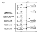
- FIG. 3 is a block diagram showing the control unit 33.
- the control unit 33 is configured by a common computer in which a CPU 40, a ROM 41, a RAM 42, an input unit 43, a display unit 44, external connection interfaces 45 to 49, etc. are connected to one another via a bus line 50.
- the CPU 40 controls the various drive mechanism portions by performing arithmetic processing in accordance with a control program stored in the ROM 41.
- a control program etc. for controlling the various drive mechanism portions including the rubber plug holding drive mechanism portion 4, the wire guiding drive mechanism portion 14, the wire holding drive mechanism portion 31, the wire inserting drive mechanism portion 32, the dispensing drive mechanism portion, etc. is stored.
- the RAM 42 is used as a working area when the CPU 40 performs predetermined processing.
- the input unit 43 is configured by a plurality of switches, a touch panel, etc., and is capable of accepting various instructions, various settings, and the like given to the control unit 33.
- the display unit 44 is a liquid crystal display or the like, and is capable of displaying various types of information such as a settings screen for the control unit 33 and a work screen.
- control unit 33 gives commands to the various drive mechanism portions based on the control program, and thus the following operation is performed.
- the gripping portions of the wire holding member 30 are closed to grip the wire 34 by the driving of the wire holding drive mechanism portion 31, and a single rubber plug 35 is supplied to the rubber plug supply pipe 7 by the driving of the dispensing drive mechanism portion.
- the rubber plug holding member 2 is moved from the first position to the second position by the driving of the rubber plug holding drive mechanism portion 4.
- another rubber plug 35 is supplied to the rubber plug supply pipe 7 by the driving of the dispensing drive mechanism portion, and the rubber plug supply pipe 7, the rubber plug restricting member 20, the rubber plug holding member 2, and the wire guide member 10 are moved forward by the driving of the wire inserting drive mechanism portion 32, so that the wire 34 is inserted into the rubber plug 35.
- the guide portions 11 are opened by the driving of the wire guiding drive mechanism portion 14, and the rubber plug supply pipe 7, the rubber plug restricting member 20, the rubber plug holding member 2, and the wire guide member 10 are moved rearward by the driving of the wire inserting drive mechanism portion 32, so that the wire 34 is taken out together with the rubber plug 35.
- the gripping portions of the wire holding member 30 are opened to replace the wire 34, and afterward, the gripping portions are closed to grip a wire 34 to be inserted next.
- the rubber plug holding member 2 is moved from the second position to the first position by the driving of the rubber plug holding drive mechanism portion 4, and the guide portions 11 are closed until the inner diameter of the wire insertion hole 12 becomes slightly larger than the diameter of the wire 34 by the driving of the wire guiding drive mechanism portion 14. Then, the above-described processing is repeatedly performed.
- FIGS. 4 to 7 and 9 are diagrams showing the operation of the rubber plug penetration device 1, and FIG. 8 is an enlarged view of a relevant portion in FIG. 7 .
- the rubber plug holding member 2 is located in the first position, as shown in FIG. 4 .
- a single rubber plug 35 is pressure-fed from the rubber plug supply pipe 7 via the rubber plug supply passage 22 by the driving of the dispensing drive mechanism portion and thus held in the rubber plug accommodation hole 3 of the rubber plug holding member 2.
- the distal end portion of the main body portion 35b of the rubber plug 35 abuts against the abutting portion 10a of the wire guide member.
- a wire 34 supplied by a wire supply mechanism portion which is not shown, is held by the wire holding member 30.
- the rubber plug holding member 2 is moved to the second position by the driving of the rubber plug holding drive mechanism portion 4 with the distal end portion of the main body portion 35b of the rubber plug 35 abutting against the abutting portion 10a of the wire guide member.
- the wire insertion hole 12, the rubber plug accommodation hole 3, and the penetrating hole portion 21 are made to communicate with one another, and the rubber plug 35 is in position.
- the rubber plug supply pipe 7, the rubber plug restricting member 20, the rubber plug holding member 2, and the wire guide member 10 are integrally moved toward the wire holding member 30 by the driving of the wire inserting drive mechanism portion 32.
- the end portion of the wire 34 is inserted into the inner hole 35a of the rubber plug 35 via the wire insertion hole 12 and the rubber plug accommodation hole 3.
- the end portion of the wire 34 pushes the rubber plug 35 rearward.
- the small diameter portion 35c of the rubber plug 35 is inserted into the penetrating hole portion 21, and the base end portion of the main body portion 35b of the rubber plug 35 abuts against the abutting portion 20a of the rubber plug restricting member 20.
- a rearward movement of the rubber plug 35 is restricted, and the wire 34 is inserted sufficiently until the wire 34 penetrates the inner hole 35a of the rubber plug 35.
- the central axis of the inner hole 35a of the rubber plug 35 is not offset from the central axis of the rubber plug accommodation hole 3 because the small diameter portion 35c of the rubber plug 35 is inserted into the penetrating hole portion 21.
- the wire holding member 30 grips the wire 34 and carries the wire 34 together with the rubber plug 35 to the outside as a finished component.
- the pair of guide portions 11 of the wire guide member 10 is made to approach each other, and the rubber plug holding member 2 is moved to the first position by the driving of the rubber plug holding drive mechanism portion 4. Then, the rubber plug 35 serving as the next insertion target, which has been allowed to stand by within the rubber plug supply passage 22, is held in the rubber plug accommodation hole 3.
- insertion of the wire 34 into the rubber plug 35 can be performed by moving the rubber plug holding member 2 to the second position, which is located laterally to the first position, and furthermore, during insertion of the wire 34 into the rubber plug 35, the operation for suppressing a movement of the rubber plug 35 in the insertion direction of the wire 34, such as the operation of advancing/retracting a core pin main body portion, is unnecessary. Therefore, insertion of the wire 34 into the rubber plug 35 can be performed quickly.
- the wire 34 is inserted into the rubber plug 35 in a state in which the small diameter portion 35c of the rubber plug 35 is inserted into the penetrating hole portion 21 of the rubber plug restricting member 20, even in the case where the wire 34 is inserted into the elongated rubber plug 35, the insertion position of the wire 34 is stable, and the quality of the wire 34 is improved.
- the provision of the wire guide member 10, which is disposed between the wire holding member 30 and the rubber plug holding member 2 and guides the end portion of the wire 34 extending from the wire holding member 30 along the extension of the central axis of the rubber plug accommodation hole 3, enables the wire 34 to be accurately inserted into the rubber plug 35.
- the abutting portion 10a is formed in the wire guide member 10, and the distal end portion of the main body portion 35b of the rubber plug 35 held in the rubber plug accommodation hole 3 can abut against the abutting portion 10a in a state in which the rubber plug holding member 2 is located in the first position and in a state in which the rubber plug holding member 2 is moving between the first position and the second position, it is possible to smoothly move the rubber plug holding member 2 from the first position to the second position while maintaining the rubber plug 35 held in the rubber plug accommodation hole 3 in a stable orientation with the distal end portion of the main body portion 35b of the rubber plug 35 abutting against the abutting portion 10a of the wire guide member 10. Therefore, insertion of the wire 34 into the rubber plug 35 can be performed quickly.
- FIG. 10 is a diagram showing the operation of the rubber plug penetration device 1A according to the second embodiment
- FIG. 11 is an enlarged view of a relevant portion in FIG. 10 .
- the rubber plug penetration device 1A is a device that inserts the wire 34 into a rubber plug 35A.
- the rubber plug 35A is formed of an elastic member such as rubber and is a tubular member having a larger diameter than the rubber plug 35 of the first embodiment, and an inner hole 35a is formed inside the rubber plug 35A.
- the rubber plug 35A has a tubular main body portion 35d and a tubular small diameter portion 35e extending from one end of the main body portion 35d.
- the rubber plug penetration device 1A includes a rubber plug supply pipe 7A, a rubber plug restricting member 20A, a rubber plug holding member 2A, the wire holding member 30, the wire guide member 10, and the wire inserting drive mechanism portion 32.
- the rubber plug supply pipe 7A is formed to have an inner diameter that is larger than the outer diameter of the rubber plug 35A and smaller than a projected shape of the rubber plug 35A that is projected laterally so that a plurality of rubber plugs 35A can pass through the rubber plug supply pipe 7A while maintaining a fixed orientation.
- a rubber plug supply passage 22A communicating with the rubber plug supply pipe 7A and the penetrating hole portion 21 are formed, each extending in the front-rear direction.
- An abutting portion 20b is formed in a region around an opening of the penetrating hole portion 21 of the rubber plug restricting member 20A on the front end side of the penetrating hole portion 21.
- a distal end portion (rear end portion) of the small diameter portion 35e of the rubber plug 35A can abut against the abutting portion 20b in a state in which the end portion of the wire 34 is inserted into the inner hole 35a of the rubber plug 35A.
- the rubber plug supply passage 22A is formed to have an inner diameter that is larger than the outer diameter of the rubber plug 35A and smaller than the projected shape of the rubber plug 35A that is projected laterally so that a plurality of rubber plugs 35A can pass through the rubber plug supply passage 22A while maintaining a fixed orientation.
- the penetrating hole portion 21 is formed to have a diameter that is smaller than the outer diameter of the small diameter portion 35e of the rubber plug 35A.
- a rubber plug accommodation hole 3A is formed in the rubber plug holding member 2A.
- the rubber plug accommodation hole 3A is formed into a shape conforming to the outer circumferential shape of the rubber plug 35A. It should be noted that as long as the distal end portion of the small diameter portion 35e of the rubber plug 35A can abut against the abutting portion 20b, the rubber plug accommodation hole 3A may also be formed into a shape that is more or less larger than the rubber plug 35A such that the rubber plug 35A can more or less move within the rubber plug accommodation hole 3A.
- a rubber plug 35A that has been pressure-fed from the rubber plug supply pipe 7A via the rubber plug supply passage 22A is held in the rubber plug accommodation hole 3A, and the rubber plug holding member 2A is moved from the first position to the second position by the driving of the rubber plug holding drive mechanism portion 4 with the distal end portion of the main body portion 35d of the rubber plug 35A abutting against the abutting portion 10a.
- the rubber plug supply pipe 7A, the rubber plug restricting member 20A, the rubber plug holding member 2A, and the wire guide member 10 are integrally moved toward the wire holding member 30 by the driving of the wire inserting drive mechanism portion 32.
- the end portion of the wire 34 is inserted into the inner hole 35a of the rubber plug 35A via the wire insertion hole 12 and the rubber plug accommodation hole 3A.
- the distal end portion of the small diameter portion 35e of the rubber plug 35A abuts against the abutting portion 20b of the rubber plug restricting member 20.
- a rearward movement of the rubber plug 35A is restricted, and the wire 34 is sufficiently inserted until the wire 34 penetrates the inner hole 35a of the rubber plug 35A.
- the abutting portion 20b can stop the small diameter portion 35e of the rubber plug 35A with a wider area.
- the central axis of the inner hole 35a of the rubber plug 35A is prevented from being offset from the central axis of the rubber plug accommodation hole 3A.
- the abutting portion 20b which the distal end portion of the small diameter portion 35e of the rubber plug 35A can abut against in a state in which the end portion of the wire 34 is inserted into the inner hole 35a of the rubber plug 35A, is formed in the region around the penetrating hole portion 21A of the rubber plug restricting member 20A, the wire 34 is inserted into the rubber plug 35A with the distal end portion of the small diameter portion 35e of the rubber plug 35A abutting against the abutting portion 20b of the rubber plug restricting member 20A.
- the insertion position of the wire 34 is stable, and the wire quality is improved.
Landscapes
- Engineering & Computer Science (AREA)
- Manufacturing & Machinery (AREA)
- Architecture (AREA)
- Civil Engineering (AREA)
- Structural Engineering (AREA)
- Processing Of Terminals (AREA)
- Automatic Assembly (AREA)
Abstract
Description
- The present invention relates to a technology for inserting a wire into a rubber plug.
- An example of conventional devices for inserting a wire into a rubber plug is disclosed in
Patent Document 1. - This rubber plug penetration device includes a rubber plug supply member having a penetrating hole portion and a rubber plug supply hole portion extending outward from the middle of the penetrating hole portion, a rubber plug holding member that holds the rubber plug in an opening of the penetrating hole portion at a first end side thereof, a pin member having a core pin main body portion that can be inserted into the penetrating hole portion, a pin support member that allows the pin member to retract by opening a movable accommodation space, a wire holding member that holds an end portion of a wire along an extension of the central axis of the core pin main body portion, and a wire inserting drive mechanism portion that moves the wire and the rubber plug such that the wire and the rubber plug move relative to each other in a direction in which the wire and the rubber plug approach each other so that the end portion of the wire is inserted into an inner hole of the rubber plug.
- In this rubber plug penetration device, the rubber plug is pressure-fed by air from a rubber plug supply pipe toward the opening of the penetrating hole portion at the first end side thereof via the rubber plug supply hole portion and a middle portion of the penetrating hole portion, and the rubber plug is thus held in a rubber plug accommodation recess of the rubber plug holding member. Then, after the pin member is moved forward (toward the first end side of the penetrating hole portion), a distal end portion of the core pin main body portion is made to protrude from the pin member and pressure-fitted into the inner hole of the rubber plug within the rubber plug accommodation recess. When the rubber plug supply member, the rubber plug holding member, the pin member, and the pin support member are integrally moved toward the wire holding member by the driving of the wire inserting drive mechanism portion, the end portion of the wire is inserted into the inner hole of the rubber plug while coming into contact with the distal end portion of the core pin main body portion and causing the core pin main body portion and the pin member to be retracted. After the wire has been inserted into the rubber plug, a pair of holding portions of the rubber plug holding member is opened, and the wire holding member grips the wire and carries the wire together with the rubber plug to the outside as a finished component.
- Patent Document 1:
JP 2007-288966A - In the above rubber plug penetration device, during insertion of the wire into the rubber plug, in order to stabilize the insertion position of the wire by suppressing a backward movement of the rubber plug to the side of the penetrating hole portion, the pin member is moved to the first end side of the penetrating hole portion before the core pin main body portion is pressure-fitted. However, since the penetrating hole portion has a long length in a front-rear direction, the time taken to move the pin member to the first end side of the penetrating hole portion is prolonged, resulting in a problem that it is difficult to quickly perform insertion of the wire into the rubber plug.
- To address this issue, it is an object of the invention to enable quick insertion of a wire into a rubber plug.
- To solve the above problems, a rubber plug penetration device according to a first aspect is a rubber plug penetration device for inserting a wire into a rubber plug, the device including a supply member having a rubber plug supply path through which the rubber plug can be supplied, a wire holding member holding an end portion of the wire in an orientation in which the end portion of the wire is pointed toward the rubber plug, a rubber plug holding member having a rubber plug accommodation hole for holding the rubber plug, the rubber plug holding member being disposed so as to move between a first position at which the rubber plug accommodation hole faces an opening of the rubber plug supply path at one end side of the rubber plug supply path and a second position which is located laterally to the first position and at which the end portion of the wire lies on an extension of the central axis of the rubber plug accommodation hole, a wire inserting mechanism portion moving at least one of the wire and the rubber plug such that the wire and the rubber plug move relative to each other in a direction in which the wire and the rubber plug approach each other so that the end portion of the wire is inserted into an inner hole of the rubber plug, and a rubber plug restricting member restricting a movement of the rubber plug held in the rubber plug accommodation hole in an insertion direction of the wire in a state in which the rubber plug holding member is located in the second position.
- A second aspect is the rubber plug penetration device according to the first aspect, wherein an abutting portion is formed in the rubber plug holding member, and a front end portion of the rubber plug can abut against the abutting portion in a state in which the rubber plug holding member is located in the second position and in a state in which the rubber plug holding member is moving between the first position and the second position.
- A third aspect is the rubber plug penetration device according to the first or second aspect, wherein a hole portion into which the end portion of the wire inserted into the inner hole of the rubber plug is inserted is formed in the rubber plug restricting member, and a rear end portion of the rubber plug is inserted into the hole portion in a state in which the end portion of the wire is inserted into the inner hole of the rubber plug.
- A fourth aspect is the rubber plug penetration device according to the first or second aspect, wherein a hole portion into which the end portion of the wire inserted into the inner hole of the rubber plug is inserted is formed in the rubber plug restricting member, an abutting portion is formed in a region around the hole portion of the rubber plug restricting member, and a rear end portion of the rubber plug can abut against the abutting portion in a state in which the end portion of the wire is inserted into the inner hole of the rubber plug.
- A fifth aspect is the rubber plug penetration device according to any one of the first to fourth aspects, the device further including a wire guide member disposed between the wire holding member and the rubber plug holding member, the wire guide member guiding the end portion of the wire extending from the wire holding member along the extension of the central axis of the rubber plug accommodation hole.
- A sixth aspect is the rubber plug penetration device according to the fifth aspect, wherein an abutting portion is formed in the wire guide member, and the front end portion of the rubber plug held in the rubber plug accommodation hole can abut against the abutting portion in a state in which the rubber plug holding member is located in the first position and in a state in which the rubber plug holding member is moving between the first position and the second position.
- According to the first aspect, insertion of the wire into the rubber plug can be performed by moving the rubber plug holding member to the second position, which is located laterally to the first position, and during insertion of the wire into the rubber plug, the operation for suppressing a movement of the rubber plug in the insertion direction of the wire, such as the operation of advancing/retracting a core pin main body portion, is unnecessary. Therefore, insertion of the wire into the rubber plug can be performed quickly.
- According to the second aspect, in a state in which the rubber plug holding member is located in the second position, it is possible to allow a rubber plug serving as the next insertion target to stand by with the front end portion of the rubber plug abutting against the abutting portion of the rubber plug holding member. Also, it is possible to smoothly move the rubber plug holding member from the second position to the first position with the front end portion of the rubber plug serving as the next insertion target abutting against the abutting portion of the rubber plug holding member, and thus the rubber plug serving as the next insertion target can be quickly held in the rubber plug accommodation hole. Therefore, insertion of wires into a plurality of rubber plugs can be performed quickly.
- According to the third aspect, the wire is inserted into the rubber plug with the rear end portion of the rubber plug being inserted into the hole portion of the rubber plug restricting member. Thus, even in the case where a wire is inserted into an elongated rubber plug, the insertion position of the wire is stable, and the wire quality is improved.
- According to the fourth aspect, since the wire is inserted into the rubber plug with the rear end portion of the rubber plug abutting against the abutting portion of the rubber plug restricting member, the insertion position of the wire is stable, and the wire quality is improved.
- According to the fifth aspect, the wire can be accurately inserted into the rubber plug.
- According to the sixth aspect, it is possible to smoothly move the rubber plug holding member from the first position to the second position while maintaining the rubber plug in a stable orientation with the front end portion of the rubber plug held in the rubber plug accommodation hole abutting against the abutting portion of the wire guide member. Therefore, insertion of the wire into the rubber plug can be performed quickly.
-
-
FIG. 1 is a front view showing a rubber plug penetration device serving as a part of cutting and crimping equipment according to a first embodiment. -
FIG. 2 is an explanatory diagram showing the above rubber plug penetration device. -
FIG. 3 is a block diagram showing a control unit of the above rubber plug penetration device. -
FIG. 4 is a diagram showing the operation of the above rubber plug penetration device. -
FIG. 5 is a diagram showing the operation of the above rubber plug penetration device. -
FIG. 6 is a diagram showing the operation of the above rubber plug penetration device. -
FIG. 7 is a diagram showing the operation of the above rubber plug penetration device. -
FIG. 8 is an enlarged view of a relevant portion inFIG. 7 . -
FIG. 9 is a diagram showing the operation of the above rubber plug penetration device. -
FIG. 10 is a diagram showing the operation of a rubber plug penetration device according to a second embodiment. -
FIG. 11 is an enlarged view of a relevant portion inFIG. 10 . - Hereinafter, a rubber
plug penetration device 1 according to a first embodiment will be described.FIG. 1 is a front view showing the rubber plug penetration device serving as a part of cutting and crimping equipment, andFIG. 2 is an explanatory diagram showing the rubberplug penetration device 1. - Provided in the cutting and crimping equipment (not shown) are a parts feeder (not shown) that aligns the orientations of a plurality of rubber plugs, a dispensing device (not shown) that separates a plurality of rubber plugs supplied from the parts feeder and supplies the rubber plugs one by one, a cutting and crimping machine (not shown) that cuts a wire and crimps a terminal onto the wire, as well as the rubber
plug penetration device 1, a rubberplug penetration device 1A, a rubberplug penetration device 1B, etc. that insert a wire into a rubber plug. It should be noted that the rubberplug penetration device 1, the rubberplug penetration device 1A, and the rubberplug penetration device 1B are different devices that insert wires into different types of rubber plugs. The rubberplug penetration device 1 will be described in the first embodiment. The rubberplug penetration device 1A will be described in a second embodiment. The rubberplug penetration device 1B has substantially the same structure as the rubberplug penetration device 1 or the rubberplug penetration device 1A, and therefore a description thereof is omitted. - Now, the rubber
plug penetration device 1 will be described. The rubberplug penetration device 1 is a device that inserts awire 34 into arubber plug 35. The rubberplug penetration device 1 includes a rubberplug restricting member 20 having a rubber plug supply passage 22 (rubber plug supply path) communicating with a rubberplug supply pipe 7, a rubberplug holding member 2, awire holding member 30, awire guide member 10, and a wire insertingdrive mechanism portion 32. The rubberplug restricting member 20 and the rubberplug holding member 2 are coupled to each other by a pair of left andright coupling members plug holding member 2 is movable in a width direction thereof. It should be noted that the rubberplug restricting member 20 corresponds to a supply member. Alternatively, it is possible to provide a supply member separately from the rubberplug restricting member 20 and form the rubber plug supply path in this supply member. - As shown in
FIG. 8 , therubber plug 35 is an elongated tubular member formed of an elastic member such as rubber, and aninner hole 35a is formed inside therubber plug 35. Therubber plug 35 has a tubularmain body portion 35b and a tubularsmall diameter portion 35c protruding from one end of themain body portion 35b. Theinner hole 35a is formed to have such a dimension that allows an inner circumferential surface of theinner hole 35a to come into close contact with an outer circumferential surface of thewire 34 in a state in which thewire 34 is inserted into theinner hole 35a. Therubber plug 35 has a function of preventing entry of water along thewire 34 in a state in which thewire 34 is installed in a predetermined component or device. - The rubber
plug supply pipe 7 is a pipe-shaped member for supplying therubber plug 35. The rubberplug supply pipe 7 is formed to have an inner diameter that is larger than the outer diameter of therubber plug 35 and smaller than a projected shape of therubber plug 35 that is projected laterally so that a plurality of rubber plugs 35 can pass through the rubberplug supply pipe 7 while maintaining a fixed orientation. In the rubberplug supply pipe 7, rubber plugs 35 are supplied one by one by the dispensing device, and air is supplied by an air supply means, which is not shown. It should be noted that in this embodiment, during operation of the rubberplug penetration device 1, air is continuously supplied by the air supply means, but air may also be periodically supplied at predetermined timings. - The rubber
plug restricting member 20 is a member for restricting a movement of therubber plug 35 in an insertion direction of thewire 34 during insertion of thewire 34 into therubber plug 35 held in a rubberplug accommodation hole 3, which will be described later. In the rubberplug restricting member 20, the rubberplug supply passage 22 communicating with the rubberplug supply pipe 7 and a penetrating hole portion 21 (hole portion) into which an end portion of thewire 34 inserted in theinner hole 35a of therubber plug 35 is inserted during insertion of thewire 34 into therubber plug 35 are formed, each extending in the front-rear direction. - The rubber
plug supply passage 22 is formed to have an inner diameter that is larger than the outer diameter of therubber plug 35 and smaller than the projected shape of therubber plug 35 that is projected laterally so that a plurality of rubber plugs 35 can pass through the rubberplug supply passage 22 while maintaining a fixed orientation. - The penetrating
hole portion 21 is formed to have a diameter that is larger than (in this embodiment, that is slightly larger than) the outer diameter of thesmall diameter portion 35c (rear end portion) of therubber plug 35 and smaller than the outer diameter of themain body portion 35b of therubber plug 35 so that thesmall diameter portion 35c of therubber plug 35 can be inserted into the penetratinghole portion 21 in a state in which the end portion of thewire 34 is inserted into theinner hole 35a of therubber plug 35. Thus, themain body portion 35b of therubber plug 35 is prevented from being inserted into the penetratinghole portion 21. Also, in a region around an opening of the penetratinghole portion 21 of the rubberplug restricting member 20 on a front end side of the penetratinghole portion 21, an abuttingportion 20a (seeFIG. 8 ) is formed, and a base end portion of themain body portion 35b of therubber plug 35 can abut against the abuttingportion 20a in a state in which thesmall diameter portion 35c of therubber plug 35 is inserted into the penetratinghole portion 21. - The rubber
plug holding member 2 is a member that holds arubber plug 35 that has been pressure-fed from the rubberplug supply pipe 7 via the rubberplug supply passage 22. In the rubberplug holding member 2, the rubberplug accommodation hole 3 for accommodating and holding therubber plug 35 that has been pressure-fed from the rubberplug supply pipe 7 via the rubberplug supply passage 22 is formed, extending in the front-rear direction. The rubberplug accommodation hole 3 is formed into a shape conforming to the outer circumferential shape of therubber plug 35, and in a state in which the rubberplug holding member 2 is located in a first position, which will be described later, therubber plug 35 is held in a substantially fixed orientation with an opening of theinner hole 35a of therubber plug 35 at a rear end side of theinner hole 35a facing an opening of the rubberplug supply passage 22 at a front end side thereof. On the other hand, in a state in which the rubberplug holding member 2 is located in a second position, which will be described later, therubber plug 35 is held in a substantially fixed orientation with the opening of theinner hole 35a of therubber plug 35 at the rear end side of theinner hole 35a facing the opening of the penetratinghole portion 21 of the rubberplug restricting member 20 at the front end side of the penetratinghole portion 21. - It should be noted that as long as the
small diameter portion 35c of therubber plug 35 can be inserted into the penetratinghole portion 21 of the rubberplug restricting member 20, the rubberplug accommodation hole 3 may also be formed into a shape that is more or less larger than therubber plug 35 such that therubber plug 35 can more or less move within the rubberplug accommodation hole 3. - The rubber
plug holding member 2 is provided with a rubber plug holdingdrive mechanism portion 4. The rubber plug holdingdrive mechanism portion 4 allows the rubberplug holding member 2 to move between the first position at which the rubberplug accommodation hole 3 faces the opening of the rubberplug supply passage 22 at the front end side thereof and the second position which is located laterally to the first position and at which the end portion of thewire 34 lies on the extension of the central axis of the rubberplug accommodation hole 3. Here, the first position is a position at which therubber plug 35 that has been supplied from the rubberplug supply pipe 7 via the rubberplug supply passage 22 is taken into and held in the rubberplug accommodation hole 3. The second position is a position at which therubber plug 35 is held in the rubberplug accommodation hole 3 so that thewire 34 can be inserted into theinner hole 35a of therubber plug 35. The rubber plug holdingdrive mechanism portion 4 is configured by a drive mechanism including a well-known actuator such as an air cylinder or a linear motor. It should be noted that it is also possible to adopt a rotary rubber plug holding member and adopt a configuration in which the rubber plug holding member moves between the first and second positions along a circular path. - An
abutting portion 2a (seeFIG. 6 ) is formed on a rear surface of the rubberplug holding member 2. A distal end portion (front end portion) of themain body portion 35b of therubber plug 35 can abut against the abuttingportion 2a in a state in which the rubberplug holding member 2 is located in the second position and in a state in which the rubberplug holding member 2 is moving between the first position and the second position. Accordingly, when the rubberplug holding member 2 is located in the second position, it is possible to allow the nexttarget rubber plug 35 that has been supplied from the rubberplug supply pipe 7 via the rubberplug supply passage 22 to stand by within the rubberplug supply passage 22 while abutting against the abuttingportion 2a. Furthermore, after thewire 34 has been inserted into therubber plug 35, the rubberplug holding member 2 can smoothly move between the first position and the second position with the distal end portion of themain body portion 35b of the nexttarget rubber plug 35 abutting against the abuttingportion 2a. It should be noted that in order to allow a plurality of rubber plugs 35 to stand by, the distal end portion of themain body portion 35b of arubber plug 35 that comes after a rubber plug currently abutting against the abuttingportion 2a is made to abut against a distal end portion of thesmall diameter portion 35c of the rubber plug currently abutting against the abuttingportion 2a, and in this manner, it is possible to allow the plurality of rubber plugs 35 to stand by within the rubberplug supply passage 22. - The
wire guide member 10 is provided between thewire holding member 30 and the rubberplug holding member 2 and is a member for guiding thewire 34 from the front side of the rubberplug holding member 2 along an extension of the central axis of the rubberplug accommodation hole 3 in a state in which the rubberplug holding member 2 is located in the second position. Thewire guide member 10 has a pair ofguide portions 11 and a wire guidingdrive mechanism portion 14 and is configured so that the wire guidingdrive mechanism portion 14 can open/close the pair ofguide portions 11. Awire insertion hole 12 into which thewire 34 can be inserted is formed between the pair ofguide portions 11, and atapered guide surface 13 surrounding thewire insertion hole 12 and spreading outward with its diameter gradually increasing is formed. - The dimension of the
wire insertion hole 12 in the diameter direction of thewire 34 varies depending on the open/close state of the pair ofguide portions 11. In the initial state and during wire insertion, the pair ofguide portions 11 is made to approach each other so that the distance therebetween becomes slightly larger than the diameter of thewire 34. When thewire 34 and therubber plug 35 are to be taken out as a finished component, the pair ofguide portions 11 is opened so that the dimension of thewire insertion hole 12 in the diameter direction of thewire 34 becomes larger than the outer diameter of therubber plug 35. - In a state in which the rubber
plug holding member 2 is located in the second position, thewire insertion hole 12 is located on an extension line of the rubberplug accommodation hole 3. Accordingly, the end portion of thewire 34 passes through thewire insertion hole 12 and is guided toward theinner hole 35a of therubber plug 35 within the rubberplug accommodation hole 3. At this time, even when thewire 34 is more or less bent with its distal end portion being in an eccentric position with respect to thewire insertion hole 12, the end portion of thewire 34 slides on the taperedguide surface 13 and is guided toward thewire insertion hole 12. The wire guidingdrive mechanism portion 14 is configured by a drive mechanism including a well-known actuator such as an air cylinder or a linear motor. - An
abutting portion 10a is formed on a rear surface of thewire guide member 10. The distal end portion of themain body portion 35b of therubber plug 35 held in the rubberplug accommodation hole 3 can abut against the abuttingportion 10a in a state in which the rubberplug holding member 2 is located in the first position and in a state in which the rubberplug holding member 2 is moving between the first position and the second position. Thus, the rubberplug holding member 2 can smoothly move between the first position and the second position with the distal end portion of themain body portion 35b abutting against the abuttingportion 10a. - The
wire holding member 30 is provided in front of thewire guide member 10 and holds the end portion of thewire 34 in an orientation in which thewire 34 is pointed toward thewire insertion hole 12 of thewire guide member 10 and therubber plug 35 held in the rubberplug accommodation hole 3. Thewire holding member 30 has the wire holdingdrive mechanism portion 31 and is configured to sandwich and hold thewire 34 between a pair of gripping portions, which is not shown, by the driving of the wire holdingdrive mechanism portion 31. The wire holdingdrive mechanism portion 31 is configured by a drive mechanism including a well-known actuator such as an air cylinder or a linear motor. - The wire inserting
drive mechanism portion 32 is a drive mechanism for inserting the end portion of thewire 34 into theinner hole 35a of therubber plug 35 by moving therubber plug 35 to the side of thewire 34, and is configured by a drive mechanism including a well-known actuator such as an air cylinder or a linear motor. According to this embodiment, the rubberplug holding member 2, the rubberplug supply pipe 7, thewire guide member 10, and the rubberplug restricting member 20 are integrally moved to the side of thewire 34. It should be noted that the details of the operation during insertion of the end portion of thewire 34 into theinner hole 35a of therubber plug 35 will be described later. - It should be noted that it is also possible to move the
wire 34 to the side of therubber plug 35, instead of moving therubber plug 35. That is to say, various configurations capable of moving thewire 34 and therubber plug 35 relative to each other to make them approach each other can be adopted as the wire insertingdrive mechanism portion 32. - The dispensing device has a dispensing drive mechanism portion, which is not shown, and separates a plurality of rubber plugs 35 supplied from the parts feeder and supplies the rubber plugs 35 one by one to the rubber
plug supply pipe 7 by the driving of the dispensing drive mechanism portion. The dispensing drive mechanism portion is configured by a drive mechanism including a well-known actuator such as an air cylinder or a linear motor. The rubber plug holdingdrive mechanism portion 4, the wire guidingdrive mechanism portion 14, the wire holdingdrive mechanism portion 31, the wire insertingdrive mechanism portion 32, the dispensing drive mechanism portion, etc. perform the following operation under the control of thecontrol unit 33. - Next, the
control unit 33 will be described.FIG. 3 is a block diagram showing thecontrol unit 33. Thecontrol unit 33 is configured by a common computer in which aCPU 40, aROM 41, aRAM 42, aninput unit 43, adisplay unit 44, external connection interfaces 45 to 49, etc. are connected to one another via abus line 50. - The
CPU 40 controls the various drive mechanism portions by performing arithmetic processing in accordance with a control program stored in theROM 41. - In the
ROM 41, a control program etc. for controlling the various drive mechanism portions including the rubber plug holdingdrive mechanism portion 4, the wire guidingdrive mechanism portion 14, the wire holdingdrive mechanism portion 31, the wire insertingdrive mechanism portion 32, the dispensing drive mechanism portion, etc. is stored. - The
RAM 42 is used as a working area when theCPU 40 performs predetermined processing. - The
input unit 43 is configured by a plurality of switches, a touch panel, etc., and is capable of accepting various instructions, various settings, and the like given to thecontrol unit 33. - The
display unit 44 is a liquid crystal display or the like, and is capable of displaying various types of information such as a settings screen for thecontrol unit 33 and a work screen. - When the control program is executed, the
control unit 33 gives commands to the various drive mechanism portions based on the control program, and thus the following operation is performed. The gripping portions of thewire holding member 30 are closed to grip thewire 34 by the driving of the wire holdingdrive mechanism portion 31, and asingle rubber plug 35 is supplied to the rubberplug supply pipe 7 by the driving of the dispensing drive mechanism portion. - Then, the rubber
plug holding member 2 is moved from the first position to the second position by the driving of the rubber plug holdingdrive mechanism portion 4. After the movement of the rubber plug holding member to the second position has been completed, anotherrubber plug 35 is supplied to the rubberplug supply pipe 7 by the driving of the dispensing drive mechanism portion, and the rubberplug supply pipe 7, the rubberplug restricting member 20, the rubberplug holding member 2, and thewire guide member 10 are moved forward by the driving of the wire insertingdrive mechanism portion 32, so that thewire 34 is inserted into therubber plug 35. After the insertion of thewire 34 into therubber plug 35 has been completed, theguide portions 11 are opened by the driving of the wire guidingdrive mechanism portion 14, and the rubberplug supply pipe 7, the rubberplug restricting member 20, the rubberplug holding member 2, and thewire guide member 10 are moved rearward by the driving of the wire insertingdrive mechanism portion 32, so that thewire 34 is taken out together with therubber plug 35. - Subsequently, by the driving of the wire holding
drive mechanism portion 31, the gripping portions of thewire holding member 30 are opened to replace thewire 34, and afterward, the gripping portions are closed to grip awire 34 to be inserted next. The rubberplug holding member 2 is moved from the second position to the first position by the driving of the rubber plug holdingdrive mechanism portion 4, and theguide portions 11 are closed until the inner diameter of thewire insertion hole 12 becomes slightly larger than the diameter of thewire 34 by the driving of the wire guidingdrive mechanism portion 14. Then, the above-described processing is repeatedly performed. - The operation of the rubber
plug penetration device 1 having the above-described configuration will be described.FIGS. 4 to 7 and9 are diagrams showing the operation of the rubberplug penetration device 1, andFIG. 8 is an enlarged view of a relevant portion inFIG. 7 . - First, in the initial state, the rubber
plug holding member 2 is located in the first position, as shown inFIG. 4 . In this state, asingle rubber plug 35 is pressure-fed from the rubberplug supply pipe 7 via the rubberplug supply passage 22 by the driving of the dispensing drive mechanism portion and thus held in the rubberplug accommodation hole 3 of the rubberplug holding member 2. At this time, the distal end portion of themain body portion 35b of therubber plug 35 abuts against the abuttingportion 10a of the wire guide member. Also, awire 34 supplied by a wire supply mechanism portion, which is not shown, is held by thewire holding member 30. - Then, as shown in
FIG. 5 , the rubberplug holding member 2 is moved to the second position by the driving of the rubber plug holdingdrive mechanism portion 4 with the distal end portion of themain body portion 35b of therubber plug 35 abutting against the abuttingportion 10a of the wire guide member. Thus, thewire insertion hole 12, the rubberplug accommodation hole 3, and the penetratinghole portion 21 are made to communicate with one another, and therubber plug 35 is in position. At this time, as shown inFIG. 6 , when arubber plug 35 serving as the next insertion target is pressure-fed from the rubberplug supply pipe 7 by the driving of the dispensing drive mechanism portion, the distal end portion of themain body portion 35b of thatrubber plug 35 abuts against the abuttingportion 2a of the rubberplug holding member 2, and therubber plug 35 is allowed to stand by in the vicinity of the opening of the rubberplug supply passage 22 at the front end side thereof. - The rubber
plug supply pipe 7, the rubberplug restricting member 20, the rubberplug holding member 2, and thewire guide member 10 are integrally moved toward thewire holding member 30 by the driving of the wire insertingdrive mechanism portion 32. As a result, as shown inFIGS. 7 and8 , the end portion of thewire 34 is inserted into theinner hole 35a of therubber plug 35 via thewire insertion hole 12 and the rubberplug accommodation hole 3. During insertion of thewire 34 into therubber plug 35, the end portion of thewire 34 pushes therubber plug 35 rearward. Thus, thesmall diameter portion 35c of therubber plug 35 is inserted into the penetratinghole portion 21, and the base end portion of themain body portion 35b of therubber plug 35 abuts against the abuttingportion 20a of the rubberplug restricting member 20. Thus, a rearward movement of therubber plug 35 is restricted, and thewire 34 is inserted sufficiently until thewire 34 penetrates theinner hole 35a of therubber plug 35. - Here, during insertion of the
wire 34 into theelongated rubber plug 35, even in the case where the rubberplug accommodation hole 3 is formed into a shape that is more or less larger than therubber plug 35, and therubber plug 35 is formed into such a size that allows therugger plug 35 to more or less move within the rubberplug accommodation hole 3, the central axis of theinner hole 35a of therubber plug 35 is not offset from the central axis of the rubberplug accommodation hole 3 because thesmall diameter portion 35c of therubber plug 35 is inserted into the penetratinghole portion 21. - After the
wire 34 has been inserted into therubber plug 35 as described above, as shown inFIG. 9 , in a state in which the pair ofguide portions 11 of thewire guide member 10 is opened so that theguide portions 11 are spaced apart, thewire holding member 30 grips thewire 34 and carries thewire 34 together with therubber plug 35 to the outside as a finished component. After that, as shown inFIG. 4 , the pair ofguide portions 11 of thewire guide member 10 is made to approach each other, and the rubberplug holding member 2 is moved to the first position by the driving of the rubber plug holdingdrive mechanism portion 4. Then, therubber plug 35 serving as the next insertion target, which has been allowed to stand by within the rubberplug supply passage 22, is held in the rubberplug accommodation hole 3. - With the rubber
plug penetration device 1 having the above-described configuration, insertion of thewire 34 into therubber plug 35 can be performed by moving the rubberplug holding member 2 to the second position, which is located laterally to the first position, and furthermore, during insertion of thewire 34 into therubber plug 35, the operation for suppressing a movement of therubber plug 35 in the insertion direction of thewire 34, such as the operation of advancing/retracting a core pin main body portion, is unnecessary. Therefore, insertion of thewire 34 into therubber plug 35 can be performed quickly. - In a state in which the rubber
plug holding member 2 is located in the second position, it is possible to allow arubber plug 35 serving as the next insertion target to stand by with the distal end portion of themain body portion 35b of therubber plug 35 abutting against the abuttingportion 2a of the rubberplug holding member 2. Also, it is possible to smoothly move the rubberplug holding member 2 from the second position to the first position with the distal end portion of themain body portion 35b of therubber plug 35 serving as the next insertion target abutting against the abuttingportion 2a of the rubberplug holding member 2. Thus, therubber plug 35 serving as the next insertion target can be quickly held in the rubberplug accommodation hole 3. Therefore, insertion ofwires 34 into a plurality of rubber plugs 35 can be performed quickly. - Since the
wire 34 is inserted into therubber plug 35 in a state in which thesmall diameter portion 35c of therubber plug 35 is inserted into the penetratinghole portion 21 of the rubberplug restricting member 20, even in the case where thewire 34 is inserted into theelongated rubber plug 35, the insertion position of thewire 34 is stable, and the quality of thewire 34 is improved. The provision of thewire guide member 10, which is disposed between thewire holding member 30 and the rubberplug holding member 2 and guides the end portion of thewire 34 extending from thewire holding member 30 along the extension of the central axis of the rubberplug accommodation hole 3, enables thewire 34 to be accurately inserted into therubber plug 35. - Since the abutting
portion 10a is formed in thewire guide member 10, and the distal end portion of themain body portion 35b of therubber plug 35 held in the rubberplug accommodation hole 3 can abut against the abuttingportion 10a in a state in which the rubberplug holding member 2 is located in the first position and in a state in which the rubberplug holding member 2 is moving between the first position and the second position, it is possible to smoothly move the rubberplug holding member 2 from the first position to the second position while maintaining therubber plug 35 held in the rubberplug accommodation hole 3 in a stable orientation with the distal end portion of themain body portion 35b of therubber plug 35 abutting against the abuttingportion 10a of thewire guide member 10. Therefore, insertion of thewire 34 into therubber plug 35 can be performed quickly. - Now, the rubber
plug penetration device 1A according to the second embodiment will be described.FIG. 10 is a diagram showing the operation of the rubberplug penetration device 1A according to the second embodiment, andFIG. 11 is an enlarged view of a relevant portion inFIG. 10 . It should be noted that in the description of this embodiment below, the same constituent elements as those described in the first embodiment are denoted by the same reference numerals, and descriptions thereof are omitted. - The rubber
plug penetration device 1A is a device that inserts thewire 34 into arubber plug 35A. Therubber plug 35A is formed of an elastic member such as rubber and is a tubular member having a larger diameter than therubber plug 35 of the first embodiment, and aninner hole 35a is formed inside therubber plug 35A. Therubber plug 35A has a tubularmain body portion 35d and a tubularsmall diameter portion 35e extending from one end of themain body portion 35d. - The rubber
plug penetration device 1A includes a rubberplug supply pipe 7A, a rubberplug restricting member 20A, a rubberplug holding member 2A, thewire holding member 30, thewire guide member 10, and the wire insertingdrive mechanism portion 32. - The rubber
plug supply pipe 7A is formed to have an inner diameter that is larger than the outer diameter of therubber plug 35A and smaller than a projected shape of therubber plug 35A that is projected laterally so that a plurality of rubber plugs 35A can pass through the rubberplug supply pipe 7A while maintaining a fixed orientation. - In the rubber
plug restricting member 20A, a rubber plug supply passage 22A communicating with the rubberplug supply pipe 7A and the penetratinghole portion 21 are formed, each extending in the front-rear direction. Anabutting portion 20b is formed in a region around an opening of the penetratinghole portion 21 of the rubberplug restricting member 20A on the front end side of the penetratinghole portion 21. A distal end portion (rear end portion) of thesmall diameter portion 35e of therubber plug 35A can abut against the abuttingportion 20b in a state in which the end portion of thewire 34 is inserted into theinner hole 35a of therubber plug 35A. The rubber plug supply passage 22A is formed to have an inner diameter that is larger than the outer diameter of therubber plug 35A and smaller than the projected shape of therubber plug 35A that is projected laterally so that a plurality of rubber plugs 35A can pass through the rubber plug supply passage 22A while maintaining a fixed orientation. The penetratinghole portion 21 is formed to have a diameter that is smaller than the outer diameter of thesmall diameter portion 35e of therubber plug 35A. Thus, the distal end portion of thesmall diameter portion 35e of therubber plug 35A abuts against the abuttingportion 20b, preventing thesmall diameter portion 35e of therubber plug 35A from being inserted into the penetratinghole portion 21. - A rubber
plug accommodation hole 3A is formed in the rubberplug holding member 2A. The rubberplug accommodation hole 3A is formed into a shape conforming to the outer circumferential shape of therubber plug 35A. It should be noted that as long as the distal end portion of thesmall diameter portion 35e of therubber plug 35A can abut against the abuttingportion 20b, the rubberplug accommodation hole 3A may also be formed into a shape that is more or less larger than therubber plug 35A such that therubber plug 35A can more or less move within the rubberplug accommodation hole 3A. - Next, the operation of the rubber
plug penetration device 1A will be described, but only the differences from the first embodiment will be described. Arubber plug 35A that has been pressure-fed from the rubberplug supply pipe 7A via the rubber plug supply passage 22A is held in the rubberplug accommodation hole 3A, and the rubberplug holding member 2A is moved from the first position to the second position by the driving of the rubber plug holdingdrive mechanism portion 4 with the distal end portion of themain body portion 35d of therubber plug 35A abutting against the abuttingportion 10a. Then, the rubberplug supply pipe 7A, the rubberplug restricting member 20A, the rubberplug holding member 2A, and thewire guide member 10 are integrally moved toward thewire holding member 30 by the driving of the wire insertingdrive mechanism portion 32. As a result, the end portion of thewire 34 is inserted into theinner hole 35a of the rubber plug 35A via thewire insertion hole 12 and the rubberplug accommodation hole 3A. During insertion of thewire 34 into therubber plug 35A, the distal end portion of thesmall diameter portion 35e of therubber plug 35A abuts against the abuttingportion 20b of the rubberplug restricting member 20. Thus, a rearward movement of therubber plug 35A is restricted, and thewire 34 is sufficiently inserted until thewire 34 penetrates theinner hole 35a of therubber plug 35A. - Here, since the
small diameter portion 35e of therubber plug 35A is formed to have a larger diameter than thesmall diameter portion 35c of the first embodiment, the abuttingportion 20b can stop thesmall diameter portion 35e of therubber plug 35A with a wider area. Thus, unlike the first embodiment, even without a structure of inserting thesmall diameter portion 35e into the penetratinghole portion 21, the central axis of theinner hole 35a of therubber plug 35A is prevented from being offset from the central axis of the rubberplug accommodation hole 3A. - With the rubber
plug penetration device 1A having the above-described configuration, since the abuttingportion 20b, which the distal end portion of thesmall diameter portion 35e of therubber plug 35A can abut against in a state in which the end portion of thewire 34 is inserted into theinner hole 35a of therubber plug 35A, is formed in the region around the penetratinghole portion 21A of the rubberplug restricting member 20A, thewire 34 is inserted into therubber plug 35A with the distal end portion of thesmall diameter portion 35e of therubber plug 35A abutting against the abuttingportion 20b of the rubberplug restricting member 20A. Thus, the insertion position of thewire 34 is stable, and the wire quality is improved. - Although the present invention has been described in detail above, the descriptions above are in all respects illustrative, and the present invention is not limited to those descriptions. It should be understood that innumerable variations that are not described herein can be envisaged without departing from the scope of the present invention.
Claims (6)
- A rubber plug penetration device for inserting a wire into a rubber plug, the rubber plug penetration device comprising:a supply member having a rubber plug supply path through which the rubber plug can be supplied;a wire holding member holding an end portion of the wire in an orientation in which the end portion of the wire is pointed toward the rubber plug;a rubber plug holding member having a rubber plug accommodation hole for holding the rubber plug, the rubber plug holding member being disposed so as to move between a first position at which the rubber plug accommodation hole faces an opening of the rubber plug supply path at one end side of the rubber plug supply path and a second position which is located laterally to the first position and at which the end portion of the wire lies on an extension of a central axis of the rubber plug accommodation hole;a wire inserting mechanism portion moving at least one of the wire and the rubber plug such that the wire and the rubber plug move relative to each other in a direction in which the wire and the rubber plug approach each other so that the end portion of the wire is inserted into an inner hole of the rubber plug; anda rubber plug restricting member restricting a movement of the rubber plug held in the rubber plug accommodation hole in an insertion direction of the wire in a state in which the rubber plug holding member is located in the second position.
- The rubber plug penetration device according to claim 1,
wherein an abutting portion is formed in the rubber plug holding member, and a front end portion of the rubber plug can abut against the abutting portion in a state in which the rubber plug holding member is located in the second position and in a state in which the rubber plug holding member is moving between the first position and the second position. - The rubber plug penetration device according to claim 1 or 2,
wherein a hole portion into which the end portion of the wire inserted into the inner hole of the rubber plug is inserted is formed in the rubber plug restricting member, and
a rear end portion of the rubber plug is inserted into the hole portion in a state in which the end portion of the wire is inserted into the inner hole of the rubber plug. - The rubber plug penetration device according to claim 1 or 2,
wherein a hole portion into which the end portion of the wire inserted into the inner hole of the rubber plug is inserted is formed in the rubber plug restricting member, and
an abutting portion is formed in a region around the hole portion of the rubber plug restricting member, and a rear end portion of the rubber plug can abut against the abutting portion in a state in which the end portion of the wire is inserted into the inner hole of the rubber plug. - The rubber plug penetration device according to any one of claims 1 to 4, further comprising:a wire guide member disposed between the wire holding member and the rubber plug holding member, the wire guide member guiding the end portion of the wire extending from the wire holding member along the extension of the central axis of the rubber plug accommodation hole.
- The rubber plug penetration device according to claim 5,
wherein an abutting portion is formed in the wire guide member, and the front end portion of the rubber plug held in the rubber plug accommodation hole can abut against the abutting portion in a state in which the rubber plug holding member is located in the first position and in a state in which the rubber plug holding member is moving between the first position and the second position.
Applications Claiming Priority (2)
| Application Number | Priority Date | Filing Date | Title |
|---|---|---|---|
| JP2011249716A JP5790427B2 (en) | 2011-11-15 | 2011-11-15 | Rubber stopper insertion device |
| PCT/JP2012/069089 WO2013073236A1 (en) | 2011-11-15 | 2012-07-27 | Rubber plug penetration device |
Publications (2)
| Publication Number | Publication Date |
|---|---|
| EP2768097A4 EP2768097A4 (en) | 2014-08-20 |
| EP2768097A1 true EP2768097A1 (en) | 2014-08-20 |
Family
ID=48429319
Family Applications (1)
| Application Number | Title | Priority Date | Filing Date |
|---|---|---|---|
| EP12850436.2A Withdrawn EP2768097A1 (en) | 2011-11-15 | 2012-07-27 | Rubber plug penetration device |
Country Status (4)
| Country | Link |
|---|---|
| EP (1) | EP2768097A1 (en) |
| JP (1) | JP5790427B2 (en) |
| CN (1) | CN103947061B (en) |
| WO (1) | WO2013073236A1 (en) |
Cited By (3)
| Publication number | Priority date | Publication date | Assignee | Title |
|---|---|---|---|---|
| US10160120B2 (en) | 2013-08-09 | 2018-12-25 | Yamaha Hatsudoki Kabushiki Kaisha | Wiring structure for robot arm |
| WO2022058993A1 (en) * | 2020-09-21 | 2022-03-24 | Aptiv Technologies Limited | Automated wire kitting systems and methods |
| US12470031B2 (en) | 2020-03-31 | 2025-11-11 | Shinmaywa Industries, Ltd. | Rubber plug holding device and electric wire insertion device |
Families Citing this family (4)
| Publication number | Priority date | Publication date | Assignee | Title |
|---|---|---|---|---|
| JP6211343B2 (en) * | 2013-08-09 | 2017-10-11 | ヤマハ発動機株式会社 | Robot arm wiring structure |
| JP6272711B2 (en) * | 2014-03-03 | 2018-01-31 | 日本連続端子株式会社 | Electric wire terminal processing equipment |
| JP6061964B2 (en) * | 2015-02-02 | 2017-01-18 | 矢崎総業株式会社 | Wire sheath removal unit and method of manufacturing wire harness |
| JP7590383B2 (en) * | 2022-09-12 | 2024-11-26 | 矢崎総業株式会社 | Component mounting device, electric wire processing device, and component mounting method |
Family Cites Families (6)
| Publication number | Priority date | Publication date | Assignee | Title |
|---|---|---|---|---|
| US4653182A (en) * | 1984-04-17 | 1987-03-31 | Sumitomo Electric Industries, Ltd. | Apparatus for fitting terminals and rubber stoppers on wires |
| JPH09290332A (en) * | 1996-03-01 | 1997-11-11 | Yazaki Corp | Rubber stopper inserting device, rubber stopper supplying method, and rubber stopper inserting method |
| JP3701538B2 (en) * | 2000-02-23 | 2005-09-28 | 矢崎総業株式会社 | Rubber plug insertion device and rubber plug insertion method |
| JP2005259509A (en) * | 2004-03-11 | 2005-09-22 | Shin Meiwa Ind Co Ltd | Waterproof seal insertion device |
| JP4679839B2 (en) * | 2004-06-03 | 2011-05-11 | 新明和工業株式会社 | Method for obtaining reference position of servo motor drive system in wire processing device |
| JP2007288966A (en) | 2006-04-19 | 2007-11-01 | Sumitomo Wiring Syst Ltd | Rubber stopper insertion device |
-
2011
- 2011-11-15 JP JP2011249716A patent/JP5790427B2/en not_active Expired - Fee Related
-
2012
- 2012-07-27 CN CN201280055891.XA patent/CN103947061B/en not_active Expired - Fee Related
- 2012-07-27 WO PCT/JP2012/069089 patent/WO2013073236A1/en not_active Ceased
- 2012-07-27 EP EP12850436.2A patent/EP2768097A1/en not_active Withdrawn
Cited By (3)
| Publication number | Priority date | Publication date | Assignee | Title |
|---|---|---|---|---|
| US10160120B2 (en) | 2013-08-09 | 2018-12-25 | Yamaha Hatsudoki Kabushiki Kaisha | Wiring structure for robot arm |
| US12470031B2 (en) | 2020-03-31 | 2025-11-11 | Shinmaywa Industries, Ltd. | Rubber plug holding device and electric wire insertion device |
| WO2022058993A1 (en) * | 2020-09-21 | 2022-03-24 | Aptiv Technologies Limited | Automated wire kitting systems and methods |
Also Published As
| Publication number | Publication date |
|---|---|
| CN103947061A (en) | 2014-07-23 |
| EP2768097A4 (en) | 2014-08-20 |
| JP2013106465A (en) | 2013-05-30 |
| JP5790427B2 (en) | 2015-10-07 |
| WO2013073236A1 (en) | 2013-05-23 |
| CN103947061B (en) | 2017-05-17 |
Similar Documents
| Publication | Publication Date | Title |
|---|---|---|
| EP2768097A1 (en) | Rubber plug penetration device | |
| US6776196B2 (en) | Braid folding unit and a braid folding method of a shielded wire | |
| US10729198B2 (en) | Seam ripper | |
| US8544172B2 (en) | Clamping apparatus for a crimping machine and method for producing a crimped connection with a crimping machine and the clamping apparatus according to the invention | |
| EP3336281A1 (en) | Reinforcing bar binding machine | |
| NZ587759A (en) | Wire guide for an automatic staple gun with a substantially planar wire guide operated by a cam | |
| CN103503083B (en) | Live line changes the wire size adjusting device of mechanism | |
| JP2017536684A (en) | Center alignment unit, crimping device, and cable handling system | |
| JP6585114B2 (en) | Terminal insertion device and terminal insertion method | |
| US20120017732A1 (en) | Wire-processing machine with length-compensating unit | |
| US11851898B2 (en) | Rebar tying tool | |
| EP2484466A1 (en) | Stock feeding apparatus | |
| US20050000266A1 (en) | Pliers-type handtool having a crimping station | |
| KR101954738B1 (en) | Clip Transfer insertion device | |
| CN101964495A (en) | Electric wire backtwisting instrument | |
| JP3848569B2 (en) | Bar material supply / processing system and residual material processing method thereof | |
| JP2011255451A (en) | Guide member for inserting wire and method for inserting wire | |
| EP3431232B1 (en) | Terminal cutter for removing terminals from a carrier strip | |
| JP2020126834A (en) | Gripper unit for gripping and handling cable ends of two cables, mounting station with gripper unit and method for providing plug housing | |
| JP5088582B2 (en) | Cylindrical member insertion device | |
| EP4412014A1 (en) | Core line alignment device for multi-core cable | |
| DE10212993A1 (en) | Electrical cable shoe crimping method has cable filaments held together by insulation ring during crimping procedure | |
| EP2814123B1 (en) | Process and device for the automatic production of coaxial cables | |
| US20050133562A1 (en) | Wire-processing device | |
| EP2848328A1 (en) | Roller hemming device and roller hemming method |
Legal Events
| Date | Code | Title | Description |
|---|---|---|---|
| PUAI | Public reference made under article 153(3) epc to a published international application that has entered the european phase |
Free format text: ORIGINAL CODE: 0009012 |
|
| 17P | Request for examination filed |
Effective date: 20140515 |
|
| A4 | Supplementary search report drawn up and despatched |
Effective date: 20140711 |
|
| AK | Designated contracting states |
Kind code of ref document: A1 Designated state(s): AL AT BE BG CH CY CZ DE DK EE ES FI FR GB GR HR HU IE IS IT LI LT LU LV MC MK MT NL NO PL PT RO RS SE SI SK SM TR |
|
| DAX | Request for extension of the european patent (deleted) | ||
| GRAP | Despatch of communication of intention to grant a patent |
Free format text: ORIGINAL CODE: EPIDOSNIGR1 |
|
| STAA | Information on the status of an ep patent application or granted ep patent |
Free format text: STATUS: GRANT OF PATENT IS INTENDED |
|
| INTG | Intention to grant announced |
Effective date: 20190405 |
|
| STAA | Information on the status of an ep patent application or granted ep patent |
Free format text: STATUS: THE APPLICATION IS DEEMED TO BE WITHDRAWN |
|
| 18D | Application deemed to be withdrawn |
Effective date: 20190817 |