EP2767771B1 - Air temperature and humidity control device - Google Patents
Air temperature and humidity control device Download PDFInfo
- Publication number
- EP2767771B1 EP2767771B1 EP14155015.2A EP14155015A EP2767771B1 EP 2767771 B1 EP2767771 B1 EP 2767771B1 EP 14155015 A EP14155015 A EP 14155015A EP 2767771 B1 EP2767771 B1 EP 2767771B1
- Authority
- EP
- European Patent Office
- Prior art keywords
- contactor
- liquid desiccant
- liquid
- desiccant
- contact module
- Prior art date
- Legal status (The legal status is an assumption and is not a legal conclusion. Google has not performed a legal analysis and makes no representation as to the accuracy of the status listed.)
- Active
Links
- 239000007788 liquid Substances 0.000 claims description 99
- 239000002274 desiccant Substances 0.000 claims description 96
- XLYOFNOQVPJJNP-UHFFFAOYSA-N water Chemical compound O XLYOFNOQVPJJNP-UHFFFAOYSA-N 0.000 claims description 43
- 238000012546 transfer Methods 0.000 claims description 7
- 238000004891 communication Methods 0.000 claims description 6
- 238000011144 upstream manufacturing Methods 0.000 claims description 3
- 239000003570 air Substances 0.000 description 30
- 239000012530 fluid Substances 0.000 description 10
- 239000003507 refrigerant Substances 0.000 description 6
- 238000004378 air conditioning Methods 0.000 description 5
- 239000012267 brine Substances 0.000 description 5
- 239000000463 material Substances 0.000 description 5
- 238000005086 pumping Methods 0.000 description 5
- HPALAKNZSZLMCH-UHFFFAOYSA-M sodium;chloride;hydrate Chemical compound O.[Na+].[Cl-] HPALAKNZSZLMCH-UHFFFAOYSA-M 0.000 description 5
- KWGKDLIKAYFUFQ-UHFFFAOYSA-M lithium chloride Chemical compound [Li+].[Cl-] KWGKDLIKAYFUFQ-UHFFFAOYSA-M 0.000 description 4
- 239000012528 membrane Substances 0.000 description 4
- -1 polypropylenes Polymers 0.000 description 4
- 238000010586 diagram Methods 0.000 description 3
- 238000012856 packing Methods 0.000 description 3
- 238000005260 corrosion Methods 0.000 description 2
- 230000007797 corrosion Effects 0.000 description 2
- 230000001419 dependent effect Effects 0.000 description 2
- 238000010438 heat treatment Methods 0.000 description 2
- 229920001343 polytetrafluoroethylene Polymers 0.000 description 2
- 229920002981 polyvinylidene fluoride Polymers 0.000 description 2
- 239000011148 porous material Substances 0.000 description 2
- 238000004781 supercooling Methods 0.000 description 2
- 239000004696 Poly ether ether ketone Substances 0.000 description 1
- 239000004698 Polyethylene Substances 0.000 description 1
- 239000004642 Polyimide Substances 0.000 description 1
- 239000004743 Polypropylene Substances 0.000 description 1
- 239000006096 absorbing agent Substances 0.000 description 1
- 230000004075 alteration Effects 0.000 description 1
- 239000012080 ambient air Substances 0.000 description 1
- 230000005587 bubbling Effects 0.000 description 1
- 238000009833 condensation Methods 0.000 description 1
- 230000005494 condensation Effects 0.000 description 1
- 230000001143 conditioned effect Effects 0.000 description 1
- 238000010276 construction Methods 0.000 description 1
- 238000001816 cooling Methods 0.000 description 1
- 230000007423 decrease Effects 0.000 description 1
- 238000007791 dehumidification Methods 0.000 description 1
- 238000005516 engineering process Methods 0.000 description 1
- 239000000284 extract Substances 0.000 description 1
- 230000036541 health Effects 0.000 description 1
- 230000002209 hydrophobic effect Effects 0.000 description 1
- 230000010354 integration Effects 0.000 description 1
- 230000003993 interaction Effects 0.000 description 1
- 238000012423 maintenance Methods 0.000 description 1
- 238000000034 method Methods 0.000 description 1
- 239000004033 plastic Substances 0.000 description 1
- 229920003023 plastic Polymers 0.000 description 1
- 229920002492 poly(sulfone) Polymers 0.000 description 1
- 229920006393 polyether sulfone Polymers 0.000 description 1
- 229920002530 polyetherether ketone Polymers 0.000 description 1
- 229920000573 polyethylene Polymers 0.000 description 1
- 229920001721 polyimide Polymers 0.000 description 1
- 229920001155 polypropylene Polymers 0.000 description 1
- 230000008569 process Effects 0.000 description 1
- 230000008929 regeneration Effects 0.000 description 1
- 238000011069 regeneration method Methods 0.000 description 1
- 238000003303 reheating Methods 0.000 description 1
- 239000007787 solid Substances 0.000 description 1
- 239000000243 solution Substances 0.000 description 1
- 238000005507 spraying Methods 0.000 description 1
- 239000000126 substance Substances 0.000 description 1
- 238000006467 substitution reaction Methods 0.000 description 1
- 150000003568 thioethers Chemical class 0.000 description 1
Images


Classifications
-
- B—PERFORMING OPERATIONS; TRANSPORTING
- B01—PHYSICAL OR CHEMICAL PROCESSES OR APPARATUS IN GENERAL
- B01D—SEPARATION
- B01D53/00—Separation of gases or vapours; Recovering vapours of volatile solvents from gases; Chemical or biological purification of waste gases, e.g. engine exhaust gases, smoke, fumes, flue gases, aerosols
- B01D53/26—Drying gases or vapours
- B01D53/263—Drying gases or vapours by absorption
-
- F—MECHANICAL ENGINEERING; LIGHTING; HEATING; WEAPONS; BLASTING
- F24—HEATING; RANGES; VENTILATING
- F24F—AIR-CONDITIONING; AIR-HUMIDIFICATION; VENTILATION; USE OF AIR CURRENTS FOR SCREENING
- F24F3/00—Air-conditioning systems in which conditioned primary air is supplied from one or more central stations to distributing units in the rooms or spaces where it may receive secondary treatment; Apparatus specially designed for such systems
- F24F3/12—Air-conditioning systems in which conditioned primary air is supplied from one or more central stations to distributing units in the rooms or spaces where it may receive secondary treatment; Apparatus specially designed for such systems characterised by the treatment of the air otherwise than by heating and cooling
- F24F3/14—Air-conditioning systems in which conditioned primary air is supplied from one or more central stations to distributing units in the rooms or spaces where it may receive secondary treatment; Apparatus specially designed for such systems characterised by the treatment of the air otherwise than by heating and cooling by humidification; by dehumidification
- F24F3/1411—Air-conditioning systems in which conditioned primary air is supplied from one or more central stations to distributing units in the rooms or spaces where it may receive secondary treatment; Apparatus specially designed for such systems characterised by the treatment of the air otherwise than by heating and cooling by humidification; by dehumidification by absorbing or adsorbing water, e.g. using an hygroscopic desiccant
- F24F3/1417—Air-conditioning systems in which conditioned primary air is supplied from one or more central stations to distributing units in the rooms or spaces where it may receive secondary treatment; Apparatus specially designed for such systems characterised by the treatment of the air otherwise than by heating and cooling by humidification; by dehumidification by absorbing or adsorbing water, e.g. using an hygroscopic desiccant with liquid hygroscopic desiccants
-
- F—MECHANICAL ENGINEERING; LIGHTING; HEATING; WEAPONS; BLASTING
- F24—HEATING; RANGES; VENTILATING
- F24F—AIR-CONDITIONING; AIR-HUMIDIFICATION; VENTILATION; USE OF AIR CURRENTS FOR SCREENING
- F24F5/00—Air-conditioning systems or apparatus not covered by F24F1/00 or F24F3/00, e.g. using solar heat or combined with household units such as an oven or water heater
- F24F5/0007—Air-conditioning systems or apparatus not covered by F24F1/00 or F24F3/00, e.g. using solar heat or combined with household units such as an oven or water heater cooling apparatus specially adapted for use in air-conditioning
- F24F5/001—Compression cycle type
-
- F—MECHANICAL ENGINEERING; LIGHTING; HEATING; WEAPONS; BLASTING
- F24—HEATING; RANGES; VENTILATING
- F24F—AIR-CONDITIONING; AIR-HUMIDIFICATION; VENTILATION; USE OF AIR CURRENTS FOR SCREENING
- F24F3/00—Air-conditioning systems in which conditioned primary air is supplied from one or more central stations to distributing units in the rooms or spaces where it may receive secondary treatment; Apparatus specially designed for such systems
- F24F3/12—Air-conditioning systems in which conditioned primary air is supplied from one or more central stations to distributing units in the rooms or spaces where it may receive secondary treatment; Apparatus specially designed for such systems characterised by the treatment of the air otherwise than by heating and cooling
- F24F3/14—Air-conditioning systems in which conditioned primary air is supplied from one or more central stations to distributing units in the rooms or spaces where it may receive secondary treatment; Apparatus specially designed for such systems characterised by the treatment of the air otherwise than by heating and cooling by humidification; by dehumidification
- F24F2003/1435—Air-conditioning systems in which conditioned primary air is supplied from one or more central stations to distributing units in the rooms or spaces where it may receive secondary treatment; Apparatus specially designed for such systems characterised by the treatment of the air otherwise than by heating and cooling by humidification; by dehumidification comprising semi-permeable membrane
-
- Y—GENERAL TAGGING OF NEW TECHNOLOGICAL DEVELOPMENTS; GENERAL TAGGING OF CROSS-SECTIONAL TECHNOLOGIES SPANNING OVER SEVERAL SECTIONS OF THE IPC; TECHNICAL SUBJECTS COVERED BY FORMER USPC CROSS-REFERENCE ART COLLECTIONS [XRACs] AND DIGESTS
- Y10—TECHNICAL SUBJECTS COVERED BY FORMER USPC
- Y10T—TECHNICAL SUBJECTS COVERED BY FORMER US CLASSIFICATION
- Y10T137/00—Fluid handling
- Y10T137/8593—Systems
- Y10T137/87571—Multiple inlet with single outlet
Definitions
- the invention relates generally to an air temperature and humidity control device, and more particularly, to an air temperature and humidity control device including a liquid-liquid contactor.
- Conventional air conditioning systems generally do not perform humidity control functions.
- air conditioners based on direct expansion (DX) may be operated to condense moisture in the air through supercooling.
- the drier, supercooled air is then reheated for comfort before entering into a facility to be air conditioned.
- Significant energy is consumed during the supercooling and reheating, which renders the process inefficient.
- water condensation on metallic DX coils may cause corrosion problems, which adds to the maintenance cost of the air conditioning systems.
- the desiccant wheel is loaded with a solid desiccant and is positioned just downstream of the temperature control unit so that cooled air transversely passes a 3 ⁇ 4 section of the rotating desiccant wheel, during which the moisture in the air is absorbed by the desiccant.
- the remaining 1 ⁇ 4 section of the desiccant wheel is reheated so that the absorbed moisture can be desorbed to regenerate the desiccant.
- systems based on desiccant wheels may be space-consuming and may suffer from lack of efficiency, as heating energy is required to regenerate the desiccant.
- the desiccant wheel is relatively cumbersome and not easy to install or uninstall, the capacity and operation of the systems based on desiccant wheels are generally not modular enough to accommodate a wide range of operations.
- humidity control may be achieved with an air conditioning system having a heat pump coupled to a liquid desiccant loop so that the liquid desiccant, such as lithium chloride, can be cooled and heated by the heat pump.
- the desiccant loop includes two contact towers loaded with packing materials. Several sprinkler are provided at the top end of the tower to distribute the liquid desiccant (cooled or heated by the heat pump) onto the packing materials, while air is blown form the bottom end of the contact tower as the liquid desiccant trickles down the packing material.
- water may be absorbed from the air into the desiccant or desorbed from the desiccant into the air.
- the air may be heated or cooled by the liquid desiccant.
- the liquid desiccant system discussed above requires less energy for the desorbing of water from the liquid desiccant, i.e. the regeneration of the liquid desiccant.
- significant amount of noises e.g. bubbling noise, are generated by the system, which may disturb the ambience of the room or facility that is the subject of the system.
- the entrainment of liquid desiccant droplets into the air stream is inherent to spraying direct contact technologies.
- Such liquid desiccant entrainment (or liquid desiccant carryover) can cause corrosion of ductwork and human health issues.
- the contact towers of the above-discussed system are relatively cumbersome in construction and not easy to modulate to accommodate a wide range of operations.
- WO 2012/125909 A2 shows an air conditioning and water producing system including a heat pumping unit and a membrane contactor in thermal communication with the heat pumping unit.
- the membrane contactor is configured such that a first brine flow is cooled by the heat pumping unit and diluted at the membrane contactor.
- a distiller is in thermal communication with the heat pumping unit and the membrane contactor such that a second brine flow is heated by the heat pumping unit and conveyed through the distiller. Thermal interaction between the second brine flow and the first brine flow flowing through the distiller extracts water from the second brine flow.
- an air temperature and humidity control device comprising the features of claim 1.
- the heat pump has a condenser, an evaporator, and a compressor.
- the humidity controller includes a first contactor fluidly coupled to the evaporator.
- the first contactor includes at least one contact module having a porous sidewall that defines an internal space through which a liquid desiccant flows.
- a vacuum pump is coupled to the first contactor. The vacuum pump is configured to generate a pressure difference between an internal side and an external side of the porous sidewall such that water vapor transfers between the vacuum and the liquid desiccant.
- the condenser may be a refrigerant-air heat exchanger.
- the liquid desiccant within the at least one contact module of the first contactor may release heat and/or water vapor to a flow created by the vacuum flow.
- the porous sidewall may be permeable to water vapor and impermeable to liquid desiccant.
- the first contactor may be positioned upstream from the evaporator.
- the humidity controller further may comprise: a second contactor fluidly coupled to the evaporator, including at least one contact module having a porous sidewall that defines an internal space through which liquid desiccant flows; and a blower for generating an airflow in communication with the sidewall of the at least one contact module of the second contactor.
- a liquid-liquid contactor for use in an air temperature and humidity control device including a substantially enclosed body. At least one contact module is arranged within the body. The contact module has a porous sidewall that defines an internal space through which a first liquid flows. The porous sidewall defines an external space through which a second liquid flows.
- the first liquid may be a liquid desiccant and the second liquid may be water.
- the first liquid may be a liquid desiccant and the second liquid may be a vacuum flow.
- the porous sidewall may be permeable to water vapor and impermeable to liquid desiccant.
- the first liquid within the at least one contact module may release water vapor to the second liquid.
- the first liquid within the at least one contact module may release heat to the second liquid.
- an air temperature and humidity control device is provided with the features as defined in claim 4.
- the heat pump has a condenser, an evaporator, and a compressor.
- the humidity controller includes a first contactor fluidly coupled to the evaporator.
- the first contactor includes at least one contact module having a porous sidewall that defines an internal space through which a liquid desiccant flows.
- a liquid source is coupled to the first contactor such that a second liquid provided by the liquid source flows through the first contactor adjacent an external side of the porous sidewall. Heat and/or water vapor transfers between the second liquid and the liquid desiccant.
- the external liquid source is a water generator.
- the liquid desiccant within the at least one contact module of the first contactor may release heat and/or water vapor to the second liquid.
- the porous sidewall may be permeable to water vapor and impermeable to liquid desiccant.
- the first contactor may be positioned upstream from the evaporator.
- the humidity controller further may comprise: a second contactor fluidly coupled to the evaporator, including at least one contact module having a porous sidewall that defines an internal space through which liquid desiccant flows; and a blower for generating an airflow in communication with the sidewall of the at least one contact module of the second contactor.
- the second contactor may be arranged downstream from the first contactor.
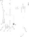
- an air temperature and humidity control device 10 includes a heat pump 20 and a humidity controller 40.
- the heat pump 20 includes a compressor 22, a condenser 24, an expansion valve 26, and an evaporator 28.
- a refrigerant R is circulated through the various components of the heat pump 20 in a known manner so that the refrigerant R is in a compressed state (releasing heat) in the condenser 24 and is in an expanded state (heat absorbing) in the evaporator 28.
- the refrigerant R is an environmentally friendly refrigerant based on R-410; however other refrigerants are within the scope of the invention.
- the humidity controller 40 may include a first contactor 42 through which a liquid desiccant LD flows, such as an aqueous lithium chloride solution for example. Other hygroscopic liquid substances may also be used as the liquid desiccant and should be considered as within the scope of this invention.
- the first contactor 42 is configured as a liquid-liquid contactor.
- the evaporator 28 thermally couples the heat pump 20 and the humidity controller 40 such that both refrigerant R and liquid desiccant LD flow there through in a heat exchange relationship.
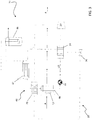
- the condenser 24 may also be a refrigerant-liquid desiccant heat exchanger configured to thermally couple the heat pump 20 and the humidity controller 40.
- the condenser 24 and/or the evaporator 28 may be of a shell-and-tube heat exchanger, in which a bundle of tubes is disposed within an outer shell. In operation, one fluid flows through the tubes and another fluid flows along the tubes (through the shell) to allow heat transfer between the two fluids.
- Other suitable heat exchangers known to one of ordinary skill in the art are also within the scope of this invention.
- the liquid desiccant LD may be driven by a fluid pump, illustrated schematically at 44, to flow sequentially through the first contactor 42 and the evaporator 28.
- a fluid pump illustrated schematically at 44
- the fluid pump 44 may be arranged at another portion of the closed loop humidity controller 40, and that the directional flow of the fluid pump 44 may be reversed to allow the liquid desiccant LD to flow sequentially through the evaporator 28 and then the first contactor 42.
- the disclosed device 10 may also include an external source 50, 56 for generating a flow of a second liquid through the first contactor 42.
- the flow of liquid may be arranged in a parallel flow, counter flow, cross-flow, or any other known relationship relative to the flow of the liquid desiccant LD through the contactor 42.
- the external source 50, 56 may include a vacuum pump coupled to the first contactor 42.
- the vacuum pump may be substituted by a water generator 56 ( FIG. 3 ).
- a water generator 56 FIG. 3
- the first contactor 42 serves as a desorber, removing moisture and/or heat from the liquid desiccant LD to regenerate the liquid desiccant.
- the humidity controller 40 may further include a second contactor 46 through which the liquid desiccant LD flows.
- the second contactor 46 may also be thermally coupled to the evaporator 28.
- liquid desiccant LD may be driven by the fluid pump 44 to flow sequentially through the first contactor 42, the evaporator 28, and the second contactor 46.
- the fluid pump 44 may be reversed to allow the liquid desiccant LD to flow sequentially through the second contactor 46, the evaporator 28, and the first contactor 42.
- a blower 52 may be provided to generate an airflow A over the second contactor 46.
- the blower 52 may include an electric fan positioned adjacent to the second contactor 46.
- the electric fan may be substituted by an air outlet of an HVAC system.
- the airflow A may be inlet air entering the building, or may be ambient air within the building.
- heat and/or water transfers between the airflow A and the liquid desiccant LD in the second contactor 46 to allow the disclosed device 10 to provide a desirable air temperature and/or humidity.
- the second contactor 46 may serve as an absorber, such that moisture and heat from airflow A is transferred to the liquid desiccant LD.
- each of the first and second contactors 42. 46 includes at least one contact module 60 having a porous sidewall 62 with an interior side 64 and an external side 66.
- the interior side 64 of the sidewall 62 defines an internal space 68 through which the liquid desiccant LD flows.
- the external side 66 similarly defines a space (not shown) through another liquid flows.
- the contact modules 60 are substantially tubular in shape.
- contactors 42, 46 that use another known humidity absorbing/desorbing device, such as a packed tower for example, are within the scope of the invention.
- Each of the contactors 42, 46 may include at least one end connector (not shown) configured to establish fluid communication between the contact modules 60 and the conduits connected to the contactors 42, 46.
- Suitable connectors include pipe manifolds, chamber manifolds, or other connectors generally used in fluid transportation.
- one or both of the contactors 42, 46 may include only one contact module 60, directly connected to the desiccant conduits without any connector.
- the porous sidewall 62 of the contact module 60 may be permeable to water vapor, and impermeable to the liquid desiccant LD so as to form a closed liquid desiccant loop.
- the porous sidewall 62 is made of a hydrophobic porous material, such as a plastic porous material for example.
- suitable materials for the porous sidewall 40 include, but are not limited to, polypropylenes, polyethylene, polysulfones, polyethersulfones, polyetheretherketones, polyimides, polypheylene sulfides, polytetrafluoroethylenes, polyvinylidene difluorides, and combinations thereof.
- the porous sidewall 40 comprises thermally-resistant polymeric materials, such as polytetrafluoroethylenes, polyvinylidene difluorides, and combinations thereof.
- the second contactor 46 is arranged generally downstream of the evaporator 28 so that the liquid desiccant LD may be cooled in the evaporator 28 to a temperature below the temperature of the airflow A passing through the second contactor 46.
- the liquid desiccant LD cools the at least one contact module 60 of the second contactor 46 as it flows there through.
- the cooled contact modules 60 are configured to absorb heat from the airflow A adjacent the exterior side 66 of the contact modules 60.
- the hygroscopic nature of the liquid desiccant LD may additionally cause the liquid desiccant to absorb water vapor from the airflow A.
- the at least one contact module 60 of the second contactor 46 decreases both the temperature and the humidity of the airflow A along its exterior side 66.
- the device 10 may be configured so that the second contactor 46 is positioned close to an interior air vent of a facility to be air-conditioned so that the airflow A, after being cooled and dehumidified by the second contactor 46, can be introduced into the facility for comfort.
- the first contactor 42 is arranged generally downstream of the second contactor 46. Because the liquid desiccant LD is heated in the second contactor 46, the need to overheat the liquid desiccant LD for moisture removal is eliminated. As the liquid desiccant LD flows through the first contactor 42, the flow generated by the vacuum pump 50 creates a low pressure environment adjacent the external side 66 of the at least one contact module 60 within the first contactor 42. The pressure differential between opposing surfaces 64, 66 of the porous sidewall 62 causes the desiccant LD to release water vapor into the vacuum flow. The resultant liquid desiccant LD is more concentrated and hygroscopic than the desiccant entering the first contactor 42. In one embodiment, the vacuum pump 50 may be configured to release the additional water vapor of the vacuum flow into the ambient, external air.
- the first contactor 42 is positioned downstream from the condenser 24 such that as the liquid desiccant LD passes through the condenser 24, the desiccant is heated. As the heated liquid desiccant flows through the at least one contact module 60 of the first contactor 42, the pressure differential created by the vacuum pump 50 across the porous sidewall 62 causes the liquid desiccant LD to release water vapor into the vacuum flow. The resultant liquid desiccant is more concentrated and hygroscopic than the desiccant entering the first contactor 42.
- the contact module 60 of the first contactor 42 heated by the liquid desiccant LD flowing there through, may release heat to the vacuum flow along the exterior side 66 of the contact modules 60.
- the contact modules 60 of the first contactor 42 may function to increase both the temperature and humidity of the vacuum flow.
- the liquid desiccant LD flowing into the first contactor 42 is heated by the condenser 24 and is configured to warm the at least one contact module 60 of the first contactor 42 as it flows there through.
- Cold water from the water generator 56 is pumped through the first contactor 42, adjacent the external side 66 of the contact modules 60, in a direction opposite the flow of the liquid desiccant LD.
- the vapor differential between opposing surfaces 64, 66 of the porous sidewall 62 causes the desiccant LD to release water vapor into the adjacent water flow.
- the resultant liquid desiccant LD is more concentrated and hygroscopic than the desiccant entering the first contactor 42.
- the contact module 60 of the first contactor 42 warmed by the liquid desiccant LD flowing there through, releases heat to the water in flow along the exterior side 66 of the contact modules 60.
- the at least one contact module 60 of the first contactor 42 may function to increase both the temperature and humidity of the water flow along its exterior side 66.
- the first contactor 42 is configured as a hot water heater, such that the heated water returning to the water generator 56 from the first contactor 42 may be provided to another source.
- a liquid-liquid contactor 42 may eliminate unnecessary heating and subsequent cooling of the liquid desiccant LD to remove moisture therefrom.
- the pressure difference created by the external source 50, 56 within the contactor 42 is enough to drive moisture from the desiccant LD. This minimizes the load on the refrigerant-liquid desiccant evaporator 30 and improves the overall efficiency of the air temperature and humidity control device 10.
Landscapes
- Engineering & Computer Science (AREA)
- Chemical & Material Sciences (AREA)
- General Engineering & Computer Science (AREA)
- Combustion & Propulsion (AREA)
- Mechanical Engineering (AREA)
- Analytical Chemistry (AREA)
- General Chemical & Material Sciences (AREA)
- Oil, Petroleum & Natural Gas (AREA)
- Chemical Kinetics & Catalysis (AREA)
- Sustainable Development (AREA)
- Life Sciences & Earth Sciences (AREA)
- Central Air Conditioning (AREA)
- Drying Of Gases (AREA)
- Physics & Mathematics (AREA)
- Thermal Sciences (AREA)
Description
- The invention relates generally to an air temperature and humidity control device, and more particularly, to an air temperature and humidity control device including a liquid-liquid contactor.
- Conventional air conditioning systems generally do not perform humidity control functions. In case humidity control is desired, air conditioners based on direct expansion (DX) may be operated to condense moisture in the air through supercooling. The drier, supercooled air is then reheated for comfort before entering into a facility to be air conditioned. Significant energy is consumed during the supercooling and reheating, which renders the process inefficient. Moreover, water condensation on metallic DX coils may cause corrosion problems, which adds to the maintenance cost of the air conditioning systems.
- In light of the need for more efficient humidity control, air conditioning systems with desiccant wheels separated from temperature control units have been developed. The desiccant wheel is loaded with a solid desiccant and is positioned just downstream of the temperature control unit so that cooled air transversely passes a ¾ section of the rotating desiccant wheel, during which the moisture in the air is absorbed by the desiccant. The remaining ¼ section of the desiccant wheel is reheated so that the absorbed moisture can be desorbed to regenerate the desiccant. While capable of achieving low humidity outputs, systems based on desiccant wheels may be space-consuming and may suffer from lack of efficiency, as heating energy is required to regenerate the desiccant. Moreover, because the desiccant wheel is relatively cumbersome and not easy to install or uninstall, the capacity and operation of the systems based on desiccant wheels are generally not modular enough to accommodate a wide range of operations.
- Besides desiccant wheels, humidity control may be achieved with an air conditioning system having a heat pump coupled to a liquid desiccant loop so that the liquid desiccant, such as lithium chloride, can be cooled and heated by the heat pump. The desiccant loop includes two contact towers loaded with packing materials. Several sprinkler are provided at the top end of the tower to distribute the liquid desiccant (cooled or heated by the heat pump) onto the packing materials, while air is blown form the bottom end of the contact tower as the liquid desiccant trickles down the packing material. As a result of the direct contact between the desiccant and air, water may be absorbed from the air into the desiccant or desorbed from the desiccant into the air. Simultaneously, the air may be heated or cooled by the liquid desiccant.
- Because of its integration with a heat pump, the liquid desiccant system discussed above requires less energy for the desorbing of water from the liquid desiccant, i.e. the regeneration of the liquid desiccant. However, as the operation of the system requires direct contact between numerous streams of liquid desiccant and air, significant amount of noises, e.g. bubbling noise, are generated by the system, which may disturb the ambience of the room or facility that is the subject of the system. The entrainment of liquid desiccant droplets into the air stream is inherent to spraying direct contact technologies. Such liquid desiccant entrainment (or liquid desiccant carryover) can cause corrosion of ductwork and human health issues. Moreover, similar to the desiccant wheels, the contact towers of the above-discussed system are relatively cumbersome in construction and not easy to modulate to accommodate a wide range of operations.
-
WO 2012/125909 A2 shows an air conditioning and water producing system including a heat pumping unit and a membrane contactor in thermal communication with the heat pumping unit. The membrane contactor is configured such that a first brine flow is cooled by the heat pumping unit and diluted at the membrane contactor. A distiller is in thermal communication with the heat pumping unit and the membrane contactor such that a second brine flow is heated by the heat pumping unit and conveyed through the distiller. Thermal interaction between the second brine flow and the first brine flow flowing through the distiller extracts water from the second brine flow. - According to one embodiment of the invention, an air temperature and humidity control device is provided comprising the features of claim 1. The heat pump has a condenser, an evaporator, and a compressor. The humidity controller includes a first contactor fluidly coupled to the evaporator. The first contactor includes at least one contact module having a porous sidewall that defines an internal space through which a liquid desiccant flows. A vacuum pump is coupled to the first contactor. The vacuum pump is configured to generate a pressure difference between an internal side and an external side of the porous sidewall such that water vapor transfers between the vacuum and the liquid desiccant.
- Preferred embodiments of this embodiment are defined in dependent claims. Particular embodiments may include any of the following optional features, alone or in combination, as long as the subject-matter is covered by the appended claims:
- The condenser may be a refrigerant-air heat exchanger.
- The liquid desiccant within the at least one contact module of the first contactor may release heat and/or water vapor to a flow created by the vacuum flow.
- The porous sidewall may be permeable to water vapor and impermeable to liquid desiccant.
- The first contactor may be positioned upstream from the evaporator.
- The humidity controller further may comprise: a second contactor fluidly coupled to the evaporator, including at least one contact module having a porous sidewall that defines an internal space through which liquid desiccant flows; and a blower for generating an airflow in communication with the sidewall of the at least one contact module of the second contactor.
- According to one embodiment, a liquid-liquid contactor for use in an air temperature and humidity control device is provided including a substantially enclosed body. At least one contact module is arranged within the body. The contact module has a porous sidewall that defines an internal space through which a first liquid flows. The porous sidewall defines an external space through which a second liquid flows.
- Particular embodiments may include any of the following optional features, alone or in combination:
The first liquid ma be a liquid desiccant and the second liquid may be water. - The first liquid may be a liquid desiccant and the second liquid may be a vacuum flow.
- The porous sidewall may be permeable to water vapor and impermeable to liquid desiccant.
- The first liquid within the at least one contact module may release water vapor to the second liquid.
- The first liquid within the at least one contact module may release heat to the second liquid.
- According to another embodiment of the invention, an air temperature and humidity control device is provided with the features as defined in claim 4. The heat pump has a condenser, an evaporator, and a compressor. The humidity controller includes a first contactor fluidly coupled to the evaporator. The first contactor includes at least one contact module having a porous sidewall that defines an internal space through which a liquid desiccant flows. A liquid source is coupled to the first contactor such that a second liquid provided by the liquid source flows through the first contactor adjacent an external side of the porous sidewall. Heat and/or water vapor transfers between the second liquid and the liquid desiccant. Preferred embodiments of this embodiment are defined in dependent claims.
- Particular embodiments may include any of the following optional features, alone or in combination, as long as the subject-matter is covered by the appended claims:
- The external liquid source is a water generator.
- The liquid desiccant within the at least one contact module of the first contactor may release heat and/or water vapor to the second liquid.
- The porous sidewall may be permeable to water vapor and impermeable to liquid desiccant.
- The first contactor may be positioned upstream from the evaporator.
- The humidity controller further may comprise: a second contactor fluidly coupled to the evaporator, including at least one contact module having a porous sidewall that defines an internal space through which liquid desiccant flows; and a blower for generating an airflow in communication with the sidewall of the at least one contact module of the second contactor.
- The second contactor may be arranged downstream from the first contactor.
- These and other advantages and features will become more apparent from the following description taken in conjunction with the drawings.
- The subject matter, which is regarded as the invention, is particularly pointed out and distinctly claimed in the claims at the conclusion of the specification. The foregoing and other features, and advantages of the invention are apparent from the following detailed description taken in conjunction with the accompanying drawings in which:
-
FIG. 1 is a schematic diagram of an air temperature and humidity control device according to an embodiment of the invention; -
FIG. 2 is a schematic diagram of another air temperature and humidity control device according to an embodiment of the invention; -
FIG. 3 is a schematic diagram of yet another air temperature and humidity control device according to an embodiment of the invention; and -
FIG. 4 is a perspective view of a cross-section of a contact module according to an embodiment of the invention. - Referring now to the FIGS., an air temperature and
humidity control device 10 includes aheat pump 20 and ahumidity controller 40. Theheat pump 20 includes acompressor 22, acondenser 24, anexpansion valve 26, and anevaporator 28. In operation, a refrigerant R is circulated through the various components of theheat pump 20 in a known manner so that the refrigerant R is in a compressed state (releasing heat) in thecondenser 24 and is in an expanded state (heat absorbing) in theevaporator 28. The refrigerant R is an environmentally friendly refrigerant based on R-410; however other refrigerants are within the scope of the invention. - The
humidity controller 40 may include afirst contactor 42 through which a liquid desiccant LD flows, such as an aqueous lithium chloride solution for example. Other hygroscopic liquid substances may also be used as the liquid desiccant and should be considered as within the scope of this invention. In one embodiment, thefirst contactor 42 is configured as a liquid-liquid contactor. Theevaporator 28 thermally couples theheat pump 20 and thehumidity controller 40 such that both refrigerant R and liquid desiccant LD flow there through in a heat exchange relationship. In another embodiment, illustrated inFIG. 2 , thecondenser 24 may also be a refrigerant-liquid desiccant heat exchanger configured to thermally couple theheat pump 20 and thehumidity controller 40. As a non-limiting example, thecondenser 24 and/or theevaporator 28 may be of a shell-and-tube heat exchanger, in which a bundle of tubes is disposed within an outer shell. In operation, one fluid flows through the tubes and another fluid flows along the tubes (through the shell) to allow heat transfer between the two fluids. Other suitable heat exchangers known to one of ordinary skill in the art are also within the scope of this invention. - As illustrated in the FIGS., the liquid desiccant LD may be driven by a fluid pump, illustrated schematically at 44, to flow sequentially through the
first contactor 42 and theevaporator 28. However, it is to be understood that thefluid pump 44 may be arranged at another portion of the closedloop humidity controller 40, and that the directional flow of thefluid pump 44 may be reversed to allow the liquid desiccant LD to flow sequentially through theevaporator 28 and then thefirst contactor 42. - The disclosed
device 10 may also include anexternal source first contactor 42. The flow of liquid may be arranged in a parallel flow, counter flow, cross-flow, or any other known relationship relative to the flow of the liquid desiccant LD through thecontactor 42. In one embodiment, illustrated in FIGS. and 2, theexternal source first contactor 42. - In another embodiment, the vacuum pump may be substituted by a water generator 56 (
FIG. 3 ). As the liquid from theexternal source first contactor 42, heat and/or water transfers between the liquid L2 and the liquid desiccant LD in thefirst contactor 42 to allow the discloseddevice 10 to provide a liquid of a desirable temperature and/or humidity. In the illustrated, non-limiting embodiments, thefirst contactor 42 serves as a desorber, removing moisture and/or heat from the liquid desiccant LD to regenerate the liquid desiccant. - The
humidity controller 40 may further include asecond contactor 46 through which the liquid desiccant LD flows. Thesecond contactor 46 may also be thermally coupled to theevaporator 28. As illustrated inFIG. 1 , liquid desiccant LD may be driven by thefluid pump 44 to flow sequentially through thefirst contactor 42, theevaporator 28, and thesecond contactor 46. Here again, thefluid pump 44 may be reversed to allow the liquid desiccant LD to flow sequentially through thesecond contactor 46, theevaporator 28, and thefirst contactor 42. - In another embodiment, a
blower 52 may be provided to generate an airflow A over thesecond contactor 46. Theblower 52 may include an electric fan positioned adjacent to thesecond contactor 46. The electric fan may be substituted by an air outlet of an HVAC system. In embodiments where the air temperature andhumidity control device 10 is arranged within a building, the airflow A may be inlet air entering the building, or may be ambient air within the building. As the airflow A passes over thesecond contactor 46, heat and/or water transfers between the airflow A and the liquid desiccant LD in thesecond contactor 46 to allow the discloseddevice 10 to provide a desirable air temperature and/or humidity. In one non-limiting embodiment, thesecond contactor 46 may serve as an absorber, such that moisture and heat from airflow A is transferred to the liquid desiccant LD. - In one non-limiting embodiment, illustrated in
FIG. 4 , each of the first andsecond contactors 42. 46 includes at least onecontact module 60 having aporous sidewall 62 with aninterior side 64 and anexternal side 66. Theinterior side 64 of thesidewall 62 defines aninternal space 68 through which the liquid desiccant LD flows. Theexternal side 66 similarly defines a space (not shown) through another liquid flows. In one embodiment, thecontact modules 60 are substantially tubular in shape. However, contactors 42, 46 that use another known humidity absorbing/desorbing device, such as a packed tower for example, are within the scope of the invention. Each of thecontactors contact modules 60 and the conduits connected to thecontactors contactors contact module 60, directly connected to the desiccant conduits without any connector. - In order to facilitate humidification and dehumidification, the
porous sidewall 62 of thecontact module 60 may be permeable to water vapor, and impermeable to the liquid desiccant LD so as to form a closed liquid desiccant loop. Thus in one embodiment, theporous sidewall 62 is made of a hydrophobic porous material, such as a plastic porous material for example. Examples of suitable materials for theporous sidewall 40 include, but are not limited to, polypropylenes, polyethylene, polysulfones, polyethersulfones, polyetheretherketones, polyimides, polypheylene sulfides, polytetrafluoroethylenes, polyvinylidene difluorides, and combinations thereof. In one embodiment, theporous sidewall 40 comprises thermally-resistant polymeric materials, such as polytetrafluoroethylenes, polyvinylidene difluorides, and combinations thereof. - Referring again to
FIG. 1 , thesecond contactor 46 is arranged generally downstream of theevaporator 28 so that the liquid desiccant LD may be cooled in theevaporator 28 to a temperature below the temperature of the airflow A passing through thesecond contactor 46. The liquid desiccant LD cools the at least onecontact module 60 of thesecond contactor 46 as it flows there through. As a result, the cooledcontact modules 60 are configured to absorb heat from the airflow A adjacent theexterior side 66 of thecontact modules 60. The hygroscopic nature of the liquid desiccant LD may additionally cause the liquid desiccant to absorb water vapor from the airflow A. Thus, the at least onecontact module 60 of thesecond contactor 46 decreases both the temperature and the humidity of the airflow A along itsexterior side 66. In generally hot and humid environments, thedevice 10 may be configured so that thesecond contactor 46 is positioned close to an interior air vent of a facility to be air-conditioned so that the airflow A, after being cooled and dehumidified by thesecond contactor 46, can be introduced into the facility for comfort. - The
first contactor 42 is arranged generally downstream of thesecond contactor 46. Because the liquid desiccant LD is heated in thesecond contactor 46, the need to overheat the liquid desiccant LD for moisture removal is eliminated. As the liquid desiccant LD flows through thefirst contactor 42, the flow generated by thevacuum pump 50 creates a low pressure environment adjacent theexternal side 66 of the at least onecontact module 60 within thefirst contactor 42. The pressure differential between opposingsurfaces porous sidewall 62 causes the desiccant LD to release water vapor into the vacuum flow. The resultant liquid desiccant LD is more concentrated and hygroscopic than the desiccant entering thefirst contactor 42. In one embodiment, thevacuum pump 50 may be configured to release the additional water vapor of the vacuum flow into the ambient, external air. - In another embodiment, illustrated in
FIG. 2 , thefirst contactor 42 is positioned downstream from thecondenser 24 such that as the liquid desiccant LD passes through thecondenser 24, the desiccant is heated. As the heated liquid desiccant flows through the at least onecontact module 60 of thefirst contactor 42, the pressure differential created by thevacuum pump 50 across theporous sidewall 62 causes the liquid desiccant LD to release water vapor into the vacuum flow. The resultant liquid desiccant is more concentrated and hygroscopic than the desiccant entering thefirst contactor 42. At the same time, thecontact module 60 of thefirst contactor 42, heated by the liquid desiccant LD flowing there through, may release heat to the vacuum flow along theexterior side 66 of thecontact modules 60. Thus, thecontact modules 60 of thefirst contactor 42 may function to increase both the temperature and humidity of the vacuum flow. - With reference now to
FIG. 3 , the liquid desiccant LD flowing into thefirst contactor 42 is heated by thecondenser 24 and is configured to warm the at least onecontact module 60 of thefirst contactor 42 as it flows there through. Cold water from thewater generator 56 is pumped through thefirst contactor 42, adjacent theexternal side 66 of thecontact modules 60, in a direction opposite the flow of the liquid desiccant LD. As the heated liquid desiccant flows through the at least onecontact module 60 of thefirst contactor 42, the vapor differential between opposingsurfaces porous sidewall 62 causes the desiccant LD to release water vapor into the adjacent water flow. The resultant liquid desiccant LD is more concentrated and hygroscopic than the desiccant entering thefirst contactor 42. At the same time, thecontact module 60 of thefirst contactor 42, warmed by the liquid desiccant LD flowing there through, releases heat to the water in flow along theexterior side 66 of thecontact modules 60. Thus, the at least onecontact module 60 of thefirst contactor 42 may function to increase both the temperature and humidity of the water flow along itsexterior side 66. In one embodiment, thefirst contactor 42 is configured as a hot water heater, such that the heated water returning to thewater generator 56 from thefirst contactor 42 may be provided to another source. - Use of a liquid-
liquid contactor 42 may eliminate unnecessary heating and subsequent cooling of the liquid desiccant LD to remove moisture therefrom. The pressure difference created by theexternal source contactor 42 is enough to drive moisture from the desiccant LD. This minimizes the load on the refrigerant-liquid desiccant evaporator 30 and improves the overall efficiency of the air temperature andhumidity control device 10. - While the invention has been described in detail in connection with only a limited number of embodiments, it should be readily understood that the invention is not limited to such disclosed embodiments. Rather, the invention can be modified to incorporate any number of variations, alterations, substitutions or equivalent arrangements not heretofore described, but which are commensurate with the scope of the invention, as defined in the claims. Additionally, while various embodiments of the invention have been described, it is to be understood that aspects of the invention may include only some of the described embodiments. Accordingly, the invention is not to be seen as limited by the foregoing description, but is only limited by the scope of the appended claims.
Claims (10)
- An air temperature and humidity control device (10) comprising:a heat pump (10) including a condenser (24), an evaporator (28), and a compressor (22);a humidity controller (40) having a first contactor (42) fluidly coupled to the evaporator (28), the first contactor (42) including at least one contact module (60), the contact module (60) having a porous sidewall (62) that defines an internal space (68) through which a liquid desiccant (LD) flows, and an external space through which a vacuum flow flows; anda vacuum pump (50) coupled to the first contactor (42) and configured to generate a pressure difference between an internal side and an external side of the porous sidewall (62) such that heat and/or water vapor transfers between the vacuum and the liquid desiccant (LD).
- The device according to claim 1, wherein the condenser (24) is a refrigerant-air heat exchanger.
- The device according to claim 1 or 2, wherein the liquid desiccant (LD) within the at least one contact module (60) of the first contactor (42) releases heat and/or water vapor to a flow created by the vacuum flow.
- An air temperature and humidity control device (10) comprising
a heat pump (20) including a condenser (24), an evaporator (28), and a compressor (22);
a humidity controller (40) having a first contactor (42) fluidly coupled to second evaporator, the first contactor (42) including at least one contact module (60), the contact module (60) having a porous sidewall (62) that defines an internal space (68) through which a liquid desiccant (LD) flows, and an external space through which water flows; and
a water generator (56) coupled to the first contactor (42) such that water provided by the water generator (56) flows through the first contactor (42), adjacent the porous sidewall (62), such that heat and/or water vapor transfers between the water and the liquid desiccant (LD). - The device according to claim 4, wherein the liquid desiccant (LD) within the at least one contact module (60) of the first contactor (42) releases heat and/or water vapor to the water.
- The device according to any of claims 1 to 5, wherein the porous sidewall (62) is permeable to water vapor and impermeable to liquid desiccant (LD).
- The device according to any of claims 1 to 6, wherein the first contactor (42) is positioned upstream from the evaporator (28).
- The device according to any of claims 1 to 7, wherein the humidity controller further comprises:a second contactor (46) fluidly coupled to the evaporator (28), including at least one contact module (60) having a porous sidewall (62) that defines an internal space through which liquid desiccant (LD) flows; anda blower (52) for generating an airflow (A) in communication with the sidewall of the at least one contact module (60) of the second contactor (46).
- The device according to claim 8, wherein the second contactor (46) is arranged downstream from the first contactor (42).
- The device according to any of claims 1 to 9, wherein the liquid-liquid module further comprises a substantially enclosed body.
Applications Claiming Priority (1)
| Application Number | Priority Date | Filing Date | Title |
|---|---|---|---|
| US201361764311P | 2013-02-13 | 2013-02-13 |
Publications (2)
| Publication Number | Publication Date |
|---|---|
| EP2767771A1 EP2767771A1 (en) | 2014-08-20 |
| EP2767771B1 true EP2767771B1 (en) | 2019-05-15 |
Family
ID=50101754
Family Applications (1)
| Application Number | Title | Priority Date | Filing Date |
|---|---|---|---|
| EP14155015.2A Active EP2767771B1 (en) | 2013-02-13 | 2014-02-13 | Air temperature and humidity control device |
Country Status (3)
| Country | Link |
|---|---|
| US (1) | US9511322B2 (en) |
| EP (1) | EP2767771B1 (en) |
| ES (1) | ES2740050T3 (en) |
Families Citing this family (23)
| Publication number | Priority date | Publication date | Assignee | Title |
|---|---|---|---|---|
| US9130503B2 (en) | 2009-05-08 | 2015-09-08 | 7Ac Technologies, Inc. | Solar energy systems |
| CN105588236B (en) | 2010-05-25 | 2019-07-09 | 7Ac技术公司 | The method and system of air conditioning and other processing is carried out using liquid drier |
| WO2012033827A1 (en) * | 2010-09-07 | 2012-03-15 | Dais Analytic Corporation | Fluid treatment systems and methods using selective transfer membranes |
| US9101875B2 (en) | 2012-06-11 | 2015-08-11 | 7Ac Technologies, Inc. | Methods and systems for turbulent, corrosion resistant heat exchangers |
| EP2929256A4 (en) | 2012-12-04 | 2016-08-03 | 7Ac Technologies Inc | METHODS AND SYSTEMS FOR COOLING BUILDINGS WITH HIGH THERMAL LOADS THROUGH DESICCANT COOLERS |
| KR20200009148A (en) | 2013-03-01 | 2020-01-29 | 7에이씨 테크놀로지스, 아이엔씨. | Desiccant air conditioning methods and systems |
| KR102099693B1 (en) | 2013-03-14 | 2020-05-15 | 7에이씨 테크놀로지스, 아이엔씨. | Methods and systems for mini-split liquid desiccant air conditioning |
| WO2014152888A1 (en) | 2013-03-14 | 2014-09-25 | 7 Ac Technologies, Inc. | Methods and systems for liquid desiccant air conditioning system retrofit |
| EP3008396B1 (en) | 2013-06-12 | 2019-10-23 | 7AC Technologies, Inc. | Liquid desiccant air conditioning system |
| CN110594883B (en) | 2014-03-20 | 2022-06-14 | 艾默生环境优化技术有限公司 | Combined heat exchanger and water injection system |
| KR20170086496A (en) | 2014-11-21 | 2017-07-26 | 7에이씨 테크놀로지스, 아이엔씨. | Methods and systems for mini-split liquid desiccant air conditioning |
| SG10201503433XA (en) * | 2015-04-30 | 2016-11-29 | Matthias Enzenhofer | Humidity Management Device And Method |
| TR201513320A2 (en) | 2015-10-26 | 2017-05-22 | Tofas Tuerk Otomobil Fabrikasi Anonim Sirketi | AN IN-CABIN COOLING SYSTEM |
| TR201514362A2 (en) | 2015-11-16 | 2017-06-21 | Tofas Tuerk Otomobil Fabrikasi Anonim Sirketi | AN AIR CONDITIONING SYSTEM |
| CN110809698B (en) | 2017-04-18 | 2021-08-10 | 北狄空气应对加拿大公司 | System and method for managing conditions in an enclosed space |
| AU2017410557A1 (en) | 2017-04-18 | 2019-12-05 | Nortek Air Solutions Canada, Inc. | Desiccant enhanced evaporative cooling systems and methods |
| WO2019089957A1 (en) | 2017-11-01 | 2019-05-09 | 7Ac Technologies, Inc. | Methods and apparatus for uniform distribution of liquid desiccant in membrane modules in liquid desiccant air-conditioning systems |
| EP3704415A4 (en) | 2017-11-01 | 2021-11-03 | 7AC Technologies, Inc. | TANK SYSTEM FOR AN AIR CONDITIONING SYSTEM WITH LIQUID DRYING AGENTS |
| US11022330B2 (en) | 2018-05-18 | 2021-06-01 | Emerson Climate Technologies, Inc. | Three-way heat exchangers for liquid desiccant air-conditioning systems and methods of manufacture |
| AU2019313490A1 (en) | 2018-07-30 | 2021-02-25 | King Abdullah University Of Science And Technology | Liquid desiccant based humidity pump, evaporative cooler, and air purification systems |
| AU2020292293B2 (en) * | 2019-06-10 | 2023-02-02 | Alliance For Sustainable Energy, Llc | Integrated desiccant-based cooling and dehumidification |
| US11859863B2 (en) * | 2019-08-16 | 2024-01-02 | Battelle Memorial Institute | Method and system for dehumidification and atmospheric water extraction with minimal energy consumption |
| US12704274B2 (en) | 2023-06-19 | 2026-08-11 | Carrier Corporation | Liquid desiccant dedicated vapor compression system and a method of operation thereof |
Family Cites Families (9)
| Publication number | Priority date | Publication date | Assignee | Title |
|---|---|---|---|---|
| GB1152440A (en) * | 1966-04-22 | 1969-05-21 | Lithonia Lighting Inc | Process and Apparatus For Cooling Air |
| US4466202A (en) * | 1983-03-07 | 1984-08-21 | Bend Research, Inc. | Energy-efficient evaporation process with means for vapor recovery |
| US6080320A (en) * | 1999-02-09 | 2000-06-27 | Von Phul; Stephen A. | Method and apparatus for removing foaming contaminants from hydrocarbon processing solvents |
| KR100436029B1 (en) * | 2001-11-23 | 2004-06-23 | 홍성섭 | Hot water generating apparatus using heat pump |
| US20090151388A1 (en) * | 2007-11-13 | 2009-06-18 | Platt Mark | Dedicated heat recovery chiller |
| US10222078B2 (en) | 2009-11-23 | 2019-03-05 | Carrier Corporation | Method and device for air conditioning with humidity control |
| ITRM20090672A1 (en) | 2009-12-21 | 2011-06-22 | Univ Degli Studi Genova | INTEGRATED AIR-CONDITIONING AND DEHUMIDIFICATION PLANT. |
| IT1402147B1 (en) | 2010-09-30 | 2013-08-28 | Univ Degli Studi Genova | CONTACTOR MODULE WITH HYDROPHOBIC CAPILLARY MEMBRANES INTEGRATED IN A HEAT EXCHANGER AND HYBRID PLANT FOR DEHUMIDIFICATION / AIR CONDITIONING. |
| EP2686615A2 (en) | 2011-03-16 | 2014-01-22 | Carrier Corporation | Air conditioning system with distilled water production from air |
-
2014
- 2014-02-10 US US14/176,210 patent/US9511322B2/en active Active
- 2014-02-13 EP EP14155015.2A patent/EP2767771B1/en active Active
- 2014-02-13 ES ES14155015T patent/ES2740050T3/en active Active
Non-Patent Citations (1)
| Title |
|---|
| None * |
Also Published As
| Publication number | Publication date |
|---|---|
| US20140223947A1 (en) | 2014-08-14 |
| ES2740050T3 (en) | 2020-02-05 |
| US9511322B2 (en) | 2016-12-06 |
| EP2767771A1 (en) | 2014-08-20 |
Similar Documents
| Publication | Publication Date | Title |
|---|---|---|
| US9511322B2 (en) | Dehumidification system for air conditioning | |
| US10222078B2 (en) | Method and device for air conditioning with humidity control | |
| EP2770266B1 (en) | Regeneration air mixing for a membrane based hygroscopic material dehumidification system | |
| EP2787293B1 (en) | Integrated membrane dehumidification system | |
| US10012401B2 (en) | Method and apparatus for conditioning air | |
| KR102396679B1 (en) | An air conditioning method using a staged process using a liquid desiccant | |
| US7188480B2 (en) | Membrane desiccation heat pump | |
| CN109475807A (en) | Units and air coolers for continuous water absorption | |
| JP2016520793A (en) | Ceiling liquid desiccant air conditioning system | |
| AU2012304223A1 (en) | Energy exchange system for conditioning air in an enclosed structure | |
| CN101680701A (en) | Evaporative cooler and desiccant assisted vapor compression AC system | |
| JP2013064549A (en) | Air conditioning system | |
| JP6377933B2 (en) | Outside air treatment device | |
| CN110678698B (en) | Air conditioning method and device | |
| US9557093B2 (en) | Industrial dehumidifier system | |
| JP2008020139A (en) | Refrigerator-less air conditioning system | |
| HK40011321A (en) | Device for continuous water absorption and an air cooler |
Legal Events
| Date | Code | Title | Description |
|---|---|---|---|
| PUAI | Public reference made under article 153(3) epc to a published international application that has entered the european phase |
Free format text: ORIGINAL CODE: 0009012 |
|
| 17P | Request for examination filed |
Effective date: 20140213 |
|
| AK | Designated contracting states |
Kind code of ref document: A1 Designated state(s): AL AT BE BG CH CY CZ DE DK EE ES FI FR GB GR HR HU IE IS IT LI LT LU LV MC MK MT NL NO PL PT RO RS SE SI SK SM TR |
|
| AX | Request for extension of the european patent |
Extension state: BA ME |
|
| R17P | Request for examination filed (corrected) |
Effective date: 20150219 |
|
| RBV | Designated contracting states (corrected) |
Designated state(s): AL AT BE BG CH CY CZ DE DK EE ES FI FR GB GR HR HU IE IS IT LI LT LU LV MC MK MT NL NO PL PT RO RS SE SI SK SM TR |
|
| GRAP | Despatch of communication of intention to grant a patent |
Free format text: ORIGINAL CODE: EPIDOSNIGR1 |
|
| STAA | Information on the status of an ep patent application or granted ep patent |
Free format text: STATUS: GRANT OF PATENT IS INTENDED |
|
| INTG | Intention to grant announced |
Effective date: 20181214 |
|
| GRAS | Grant fee paid |
Free format text: ORIGINAL CODE: EPIDOSNIGR3 |
|
| GRAA | (expected) grant |
Free format text: ORIGINAL CODE: 0009210 |
|
| STAA | Information on the status of an ep patent application or granted ep patent |
Free format text: STATUS: THE PATENT HAS BEEN GRANTED |
|
| AK | Designated contracting states |
Kind code of ref document: B1 Designated state(s): AL AT BE BG CH CY CZ DE DK EE ES FI FR GB GR HR HU IE IS IT LI LT LU LV MC MK MT NL NO PL PT RO RS SE SI SK SM TR |
|
| REG | Reference to a national code |
Ref country code: CH Ref legal event code: EP Ref country code: GB Ref legal event code: FG4D |
|
| REG | Reference to a national code |
Ref country code: IE Ref legal event code: FG4D |
|
| REG | Reference to a national code |
Ref country code: DE Ref legal event code: R096 Ref document number: 602014046688 Country of ref document: DE |
|
| REG | Reference to a national code |
Ref country code: NL Ref legal event code: FP |
|
| REG | Reference to a national code |
Ref country code: LT Ref legal event code: MG4D |
|
| PG25 | Lapsed in a contracting state [announced via postgrant information from national office to epo] |
Ref country code: AL Free format text: LAPSE BECAUSE OF FAILURE TO SUBMIT A TRANSLATION OF THE DESCRIPTION OR TO PAY THE FEE WITHIN THE PRESCRIBED TIME-LIMIT Effective date: 20190515 Ref country code: PT Free format text: LAPSE BECAUSE OF FAILURE TO SUBMIT A TRANSLATION OF THE DESCRIPTION OR TO PAY THE FEE WITHIN THE PRESCRIBED TIME-LIMIT Effective date: 20190915 Ref country code: SE Free format text: LAPSE BECAUSE OF FAILURE TO SUBMIT A TRANSLATION OF THE DESCRIPTION OR TO PAY THE FEE WITHIN THE PRESCRIBED TIME-LIMIT Effective date: 20190515 Ref country code: NO Free format text: LAPSE BECAUSE OF FAILURE TO SUBMIT A TRANSLATION OF THE DESCRIPTION OR TO PAY THE FEE WITHIN THE PRESCRIBED TIME-LIMIT Effective date: 20190815 Ref country code: HR Free format text: LAPSE BECAUSE OF FAILURE TO SUBMIT A TRANSLATION OF THE DESCRIPTION OR TO PAY THE FEE WITHIN THE PRESCRIBED TIME-LIMIT Effective date: 20190515 Ref country code: LT Free format text: LAPSE BECAUSE OF FAILURE TO SUBMIT A TRANSLATION OF THE DESCRIPTION OR TO PAY THE FEE WITHIN THE PRESCRIBED TIME-LIMIT Effective date: 20190515 Ref country code: FI Free format text: LAPSE BECAUSE OF FAILURE TO SUBMIT A TRANSLATION OF THE DESCRIPTION OR TO PAY THE FEE WITHIN THE PRESCRIBED TIME-LIMIT Effective date: 20190515 |
|
| PG25 | Lapsed in a contracting state [announced via postgrant information from national office to epo] |
Ref country code: LV Free format text: LAPSE BECAUSE OF FAILURE TO SUBMIT A TRANSLATION OF THE DESCRIPTION OR TO PAY THE FEE WITHIN THE PRESCRIBED TIME-LIMIT Effective date: 20190515 Ref country code: BG Free format text: LAPSE BECAUSE OF FAILURE TO SUBMIT A TRANSLATION OF THE DESCRIPTION OR TO PAY THE FEE WITHIN THE PRESCRIBED TIME-LIMIT Effective date: 20190815 Ref country code: RS Free format text: LAPSE BECAUSE OF FAILURE TO SUBMIT A TRANSLATION OF THE DESCRIPTION OR TO PAY THE FEE WITHIN THE PRESCRIBED TIME-LIMIT Effective date: 20190515 Ref country code: GR Free format text: LAPSE BECAUSE OF FAILURE TO SUBMIT A TRANSLATION OF THE DESCRIPTION OR TO PAY THE FEE WITHIN THE PRESCRIBED TIME-LIMIT Effective date: 20190816 |
|
| REG | Reference to a national code |
Ref country code: AT Ref legal event code: MK05 Ref document number: 1133902 Country of ref document: AT Kind code of ref document: T Effective date: 20190515 |
|
| PG25 | Lapsed in a contracting state [announced via postgrant information from national office to epo] |
Ref country code: DK Free format text: LAPSE BECAUSE OF FAILURE TO SUBMIT A TRANSLATION OF THE DESCRIPTION OR TO PAY THE FEE WITHIN THE PRESCRIBED TIME-LIMIT Effective date: 20190515 Ref country code: SK Free format text: LAPSE BECAUSE OF FAILURE TO SUBMIT A TRANSLATION OF THE DESCRIPTION OR TO PAY THE FEE WITHIN THE PRESCRIBED TIME-LIMIT Effective date: 20190515 Ref country code: EE Free format text: LAPSE BECAUSE OF FAILURE TO SUBMIT A TRANSLATION OF THE DESCRIPTION OR TO PAY THE FEE WITHIN THE PRESCRIBED TIME-LIMIT Effective date: 20190515 Ref country code: AT Free format text: LAPSE BECAUSE OF FAILURE TO SUBMIT A TRANSLATION OF THE DESCRIPTION OR TO PAY THE FEE WITHIN THE PRESCRIBED TIME-LIMIT Effective date: 20190515 Ref country code: RO Free format text: LAPSE BECAUSE OF FAILURE TO SUBMIT A TRANSLATION OF THE DESCRIPTION OR TO PAY THE FEE WITHIN THE PRESCRIBED TIME-LIMIT Effective date: 20190515 Ref country code: CZ Free format text: LAPSE BECAUSE OF FAILURE TO SUBMIT A TRANSLATION OF THE DESCRIPTION OR TO PAY THE FEE WITHIN THE PRESCRIBED TIME-LIMIT Effective date: 20190515 |
|
| REG | Reference to a national code |
Ref country code: ES Ref legal event code: FG2A Ref document number: 2740050 Country of ref document: ES Kind code of ref document: T3 Effective date: 20200205 |
|
| REG | Reference to a national code |
Ref country code: DE Ref legal event code: R097 Ref document number: 602014046688 Country of ref document: DE |
|
| PG25 | Lapsed in a contracting state [announced via postgrant information from national office to epo] |
Ref country code: SM Free format text: LAPSE BECAUSE OF FAILURE TO SUBMIT A TRANSLATION OF THE DESCRIPTION OR TO PAY THE FEE WITHIN THE PRESCRIBED TIME-LIMIT Effective date: 20190515 |
|
| PLBE | No opposition filed within time limit |
Free format text: ORIGINAL CODE: 0009261 |
|
| STAA | Information on the status of an ep patent application or granted ep patent |
Free format text: STATUS: NO OPPOSITION FILED WITHIN TIME LIMIT |
|
| PG25 | Lapsed in a contracting state [announced via postgrant information from national office to epo] |
Ref country code: TR Free format text: LAPSE BECAUSE OF FAILURE TO SUBMIT A TRANSLATION OF THE DESCRIPTION OR TO PAY THE FEE WITHIN THE PRESCRIBED TIME-LIMIT Effective date: 20190515 |
|
| 26N | No opposition filed |
Effective date: 20200218 |
|
| PG25 | Lapsed in a contracting state [announced via postgrant information from national office to epo] |
Ref country code: PL Free format text: LAPSE BECAUSE OF FAILURE TO SUBMIT A TRANSLATION OF THE DESCRIPTION OR TO PAY THE FEE WITHIN THE PRESCRIBED TIME-LIMIT Effective date: 20190515 |
|
| PG25 | Lapsed in a contracting state [announced via postgrant information from national office to epo] |
Ref country code: SI Free format text: LAPSE BECAUSE OF FAILURE TO SUBMIT A TRANSLATION OF THE DESCRIPTION OR TO PAY THE FEE WITHIN THE PRESCRIBED TIME-LIMIT Effective date: 20190515 |
|
| REG | Reference to a national code |
Ref country code: DE Ref legal event code: R119 Ref document number: 602014046688 Country of ref document: DE |
|
| REG | Reference to a national code |
Ref country code: CH Ref legal event code: PL |
|
| REG | Reference to a national code |
Ref country code: NL Ref legal event code: MM Effective date: 20200301 |
|
| GBPC | Gb: european patent ceased through non-payment of renewal fee |
Effective date: 20200213 |
|
| REG | Reference to a national code |
Ref country code: BE Ref legal event code: MM Effective date: 20200229 |
|
| PG25 | Lapsed in a contracting state [announced via postgrant information from national office to epo] |
Ref country code: MC Free format text: LAPSE BECAUSE OF FAILURE TO SUBMIT A TRANSLATION OF THE DESCRIPTION OR TO PAY THE FEE WITHIN THE PRESCRIBED TIME-LIMIT Effective date: 20190515 Ref country code: LU Free format text: LAPSE BECAUSE OF NON-PAYMENT OF DUE FEES Effective date: 20200213 |
|
| PG25 | Lapsed in a contracting state [announced via postgrant information from national office to epo] |
Ref country code: CH Free format text: LAPSE BECAUSE OF NON-PAYMENT OF DUE FEES Effective date: 20200229 Ref country code: LI Free format text: LAPSE BECAUSE OF NON-PAYMENT OF DUE FEES Effective date: 20200229 |
|
| PG25 | Lapsed in a contracting state [announced via postgrant information from national office to epo] |
Ref country code: NL Free format text: LAPSE BECAUSE OF NON-PAYMENT OF DUE FEES Effective date: 20200301 |
|
| PG25 | Lapsed in a contracting state [announced via postgrant information from national office to epo] |
Ref country code: DE Free format text: LAPSE BECAUSE OF NON-PAYMENT OF DUE FEES Effective date: 20200901 Ref country code: IE Free format text: LAPSE BECAUSE OF NON-PAYMENT OF DUE FEES Effective date: 20200213 Ref country code: GB Free format text: LAPSE BECAUSE OF NON-PAYMENT OF DUE FEES Effective date: 20200213 |
|
| PG25 | Lapsed in a contracting state [announced via postgrant information from national office to epo] |
Ref country code: BE Free format text: LAPSE BECAUSE OF NON-PAYMENT OF DUE FEES Effective date: 20200229 |
|
| REG | Reference to a national code |
Ref country code: ES Ref legal event code: FD2A Effective date: 20210705 |
|
| PG25 | Lapsed in a contracting state [announced via postgrant information from national office to epo] |
Ref country code: ES Free format text: LAPSE BECAUSE OF NON-PAYMENT OF DUE FEES Effective date: 20200214 |
|
| PG25 | Lapsed in a contracting state [announced via postgrant information from national office to epo] |
Ref country code: MT Free format text: LAPSE BECAUSE OF FAILURE TO SUBMIT A TRANSLATION OF THE DESCRIPTION OR TO PAY THE FEE WITHIN THE PRESCRIBED TIME-LIMIT Effective date: 20190515 Ref country code: CY Free format text: LAPSE BECAUSE OF FAILURE TO SUBMIT A TRANSLATION OF THE DESCRIPTION OR TO PAY THE FEE WITHIN THE PRESCRIBED TIME-LIMIT Effective date: 20190515 |
|
| PG25 | Lapsed in a contracting state [announced via postgrant information from national office to epo] |
Ref country code: MK Free format text: LAPSE BECAUSE OF FAILURE TO SUBMIT A TRANSLATION OF THE DESCRIPTION OR TO PAY THE FEE WITHIN THE PRESCRIBED TIME-LIMIT Effective date: 20190515 Ref country code: IS Free format text: LAPSE BECAUSE OF FAILURE TO SUBMIT A TRANSLATION OF THE DESCRIPTION OR TO PAY THE FEE WITHIN THE PRESCRIBED TIME-LIMIT Effective date: 20190915 |
|
| P01 | Opt-out of the competence of the unified patent court (upc) registered |
Effective date: 20230527 |
|
| PGFP | Annual fee paid to national office [announced via postgrant information from national office to epo] |
Ref country code: FR Payment date: 20250121 Year of fee payment: 12 |
|
| PGFP | Annual fee paid to national office [announced via postgrant information from national office to epo] |
Ref country code: IT Payment date: 20250121 Year of fee payment: 12 |