EP2767756A1 - Light-source device - Google Patents
Light-source device Download PDFInfo
- Publication number
- EP2767756A1 EP2767756A1 EP12840415.9A EP12840415A EP2767756A1 EP 2767756 A1 EP2767756 A1 EP 2767756A1 EP 12840415 A EP12840415 A EP 12840415A EP 2767756 A1 EP2767756 A1 EP 2767756A1
- Authority
- EP
- European Patent Office
- Prior art keywords
- excitation light
- light
- wavelength
- wavelength converting
- optical member
- Prior art date
- Legal status (The legal status is an assumption and is not a legal conclusion. Google has not performed a legal analysis and makes no representation as to the accuracy of the status listed.)
- Granted
Links
- 230000005284 excitation Effects 0.000 claims abstract description 249
- 230000003287 optical effect Effects 0.000 claims abstract description 98
- 239000000463 material Substances 0.000 claims description 56
- 239000002245 particle Substances 0.000 claims description 15
- 239000000843 powder Substances 0.000 claims description 10
- 239000013078 crystal Substances 0.000 claims description 3
- 239000003566 sealing material Substances 0.000 description 18
- 238000010521 absorption reaction Methods 0.000 description 16
- 239000013307 optical fiber Substances 0.000 description 16
- 238000010586 diagram Methods 0.000 description 13
- 230000004048 modification Effects 0.000 description 13
- 238000012986 modification Methods 0.000 description 13
- 238000005286 illumination Methods 0.000 description 12
- 238000006243 chemical reaction Methods 0.000 description 8
- 229910019655 synthetic inorganic crystalline material Inorganic materials 0.000 description 7
- 239000000919 ceramic Substances 0.000 description 6
- 229920005989 resin Polymers 0.000 description 5
- 239000011347 resin Substances 0.000 description 5
- 238000001228 spectrum Methods 0.000 description 4
- 238000009792 diffusion process Methods 0.000 description 3
- 238000007789 sealing Methods 0.000 description 3
- 235000005811 Viola adunca Nutrition 0.000 description 2
- 240000009038 Viola odorata Species 0.000 description 2
- 235000013487 Viola odorata Nutrition 0.000 description 2
- 235000002254 Viola papilionacea Nutrition 0.000 description 2
- 229920002050 silicone resin Polymers 0.000 description 2
- BPQQTUXANYXVAA-UHFFFAOYSA-N Orthosilicate Chemical compound [O-][Si]([O-])([O-])[O-] BPQQTUXANYXVAA-UHFFFAOYSA-N 0.000 description 1
- PNEYBMLMFCGWSK-UHFFFAOYSA-N aluminium oxide Inorganic materials [O-2].[O-2].[O-2].[Al+3].[Al+3] PNEYBMLMFCGWSK-UHFFFAOYSA-N 0.000 description 1
- 230000006399 behavior Effects 0.000 description 1
- 239000000945 filler Substances 0.000 description 1
- 239000011521 glass Substances 0.000 description 1
- 238000000034 method Methods 0.000 description 1
- 239000000203 mixture Substances 0.000 description 1
- 230000002093 peripheral effect Effects 0.000 description 1
- 238000010791 quenching Methods 0.000 description 1
- 230000000171 quenching effect Effects 0.000 description 1
- 230000003595 spectral effect Effects 0.000 description 1
- 239000000758 substrate Substances 0.000 description 1
- 238000002834 transmittance Methods 0.000 description 1
- 229910019901 yttrium aluminum garnet Inorganic materials 0.000 description 1
Images


Classifications
-
- G—PHYSICS
- G02—OPTICS
- G02B—OPTICAL ELEMENTS, SYSTEMS OR APPARATUS
- G02B6/00—Light guides; Structural details of arrangements comprising light guides and other optical elements, e.g. couplings
- G02B6/0001—Light guides; Structural details of arrangements comprising light guides and other optical elements, e.g. couplings specially adapted for lighting devices or systems
- G02B6/0005—Light guides; Structural details of arrangements comprising light guides and other optical elements, e.g. couplings specially adapted for lighting devices or systems the light guides being of the fibre type
- G02B6/0008—Light guides; Structural details of arrangements comprising light guides and other optical elements, e.g. couplings specially adapted for lighting devices or systems the light guides being of the fibre type the light being emitted at the end of the fibre
-
- F—MECHANICAL ENGINEERING; LIGHTING; HEATING; WEAPONS; BLASTING
- F21—LIGHTING
- F21V—FUNCTIONAL FEATURES OR DETAILS OF LIGHTING DEVICES OR SYSTEMS THEREOF; STRUCTURAL COMBINATIONS OF LIGHTING DEVICES WITH OTHER ARTICLES, NOT OTHERWISE PROVIDED FOR
- F21V13/00—Producing particular characteristics or distribution of the light emitted by means of a combination of elements specified in two or more of main groups F21V1/00 - F21V11/00
- F21V13/02—Combinations of only two kinds of elements
- F21V13/08—Combinations of only two kinds of elements the elements being filters or photoluminescent elements and reflectors
-
- F—MECHANICAL ENGINEERING; LIGHTING; HEATING; WEAPONS; BLASTING
- F21—LIGHTING
- F21V—FUNCTIONAL FEATURES OR DETAILS OF LIGHTING DEVICES OR SYSTEMS THEREOF; STRUCTURAL COMBINATIONS OF LIGHTING DEVICES WITH OTHER ARTICLES, NOT OTHERWISE PROVIDED FOR
- F21V5/00—Refractors for light sources
- F21V5/10—Refractors for light sources comprising photoluminescent material
-
- F—MECHANICAL ENGINEERING; LIGHTING; HEATING; WEAPONS; BLASTING
- F21—LIGHTING
- F21V—FUNCTIONAL FEATURES OR DETAILS OF LIGHTING DEVICES OR SYSTEMS THEREOF; STRUCTURAL COMBINATIONS OF LIGHTING DEVICES WITH OTHER ARTICLES, NOT OTHERWISE PROVIDED FOR
- F21V9/00—Elements for modifying spectral properties, polarisation or intensity of the light emitted, e.g. filters
- F21V9/40—Elements for modifying spectral properties, polarisation or intensity of the light emitted, e.g. filters with provision for controlling spectral properties, e.g. colour, or intensity
-
- A—HUMAN NECESSITIES
- A61—MEDICAL OR VETERINARY SCIENCE; HYGIENE
- A61B—DIAGNOSIS; SURGERY; IDENTIFICATION
- A61B1/00—Instruments for performing medical examinations of the interior of cavities or tubes of the body by visual or photographical inspection, e.g. endoscopes; Illuminating arrangements therefor
- A61B1/06—Instruments for performing medical examinations of the interior of cavities or tubes of the body by visual or photographical inspection, e.g. endoscopes; Illuminating arrangements therefor with illuminating arrangements
- A61B1/0638—Instruments for performing medical examinations of the interior of cavities or tubes of the body by visual or photographical inspection, e.g. endoscopes; Illuminating arrangements therefor with illuminating arrangements providing two or more wavelengths
-
- A—HUMAN NECESSITIES
- A61—MEDICAL OR VETERINARY SCIENCE; HYGIENE
- A61B—DIAGNOSIS; SURGERY; IDENTIFICATION
- A61B1/00—Instruments for performing medical examinations of the interior of cavities or tubes of the body by visual or photographical inspection, e.g. endoscopes; Illuminating arrangements therefor
- A61B1/06—Instruments for performing medical examinations of the interior of cavities or tubes of the body by visual or photographical inspection, e.g. endoscopes; Illuminating arrangements therefor with illuminating arrangements
- A61B1/0653—Instruments for performing medical examinations of the interior of cavities or tubes of the body by visual or photographical inspection, e.g. endoscopes; Illuminating arrangements therefor with illuminating arrangements with wavelength conversion
-
- F—MECHANICAL ENGINEERING; LIGHTING; HEATING; WEAPONS; BLASTING
- F21—LIGHTING
- F21Y—INDEXING SCHEME ASSOCIATED WITH SUBCLASSES F21K, F21L, F21S and F21V, RELATING TO THE FORM OR THE KIND OF THE LIGHT SOURCES OR OF THE COLOUR OF THE LIGHT EMITTED
- F21Y2115/00—Light-generating elements of semiconductor light sources
- F21Y2115/10—Light-emitting diodes [LED]
-
- F—MECHANICAL ENGINEERING; LIGHTING; HEATING; WEAPONS; BLASTING
- F21—LIGHTING
- F21Y—INDEXING SCHEME ASSOCIATED WITH SUBCLASSES F21K, F21L, F21S and F21V, RELATING TO THE FORM OR THE KIND OF THE LIGHT SOURCES OR OF THE COLOUR OF THE LIGHT EMITTED
- F21Y2115/00—Light-generating elements of semiconductor light sources
- F21Y2115/30—Semiconductor lasers
Definitions
- the present invention relates to a light source device.
- a light source device which emits light from a small solid-state light source, converts this light by a light converting member, and changes illumination light into a desired irradiation pattern or a desired color.
- International Publication No. 2008/105527 discloses a light source device which is a combination of an LED chip disposed on a metallic substrate, a sealing resin sealing the LED chip, and a fluorescent material disposed on the sealing resin.
- a plate-shaped fluorescent material disposed on the LED chip is used to convert the wavelength of part of excitation light emitted from the LED chip and then emit fluorescence.
- the technique according to International Publication No. 2008/105527 adjusts the illumination light by the excitation light that has passed through the fluorescent material and by the fluorescence emitted from the fluorescent material.
- the light source device which adjusts the illumination light by the excitation light that has passed through the fluorescent material and by the fluorescence emitted from the fluorescent material has the following problems. That is, the excitation light passing through the fluorescent material is higher in intensity in the vicinity of an optical axis and lower in intensity at a circumferential edge. In contrast, the fluorescence emitted from the fluorescent material is isotropically scattered, and has an isotropic light intensity. Thus, the illumination light emitted from such a light source device is unevenly colored light having a stronger excitation light component in the center and a weaker fluorescent component at the circumferential edge.
- a light source device is characterized by including a first excitation light source configured to emit first excitation light having a wavelength in a first wavelength region; a first optical member configured to absorb at least part of the first excitation light, convert a wavelength of the part of the first excitation light to emit first wavelength converted light, and increase divergence angle of transmitted first excitation light by a first incremental angle; a second optical member disposed in a region including at least an area which includes an optical axis of the first excitation light, light intensity regarding the first excitation light in the area being equal to or more than 1/e times (e is Napier's constant) light intensity on the optical axis, and the second optical member increasing the divergence angle of the transmitted first excitation light by a second incremental angle larger than the first incremental angle; and a holding member which holds the first optical member and the second optical member.
- a first excitation light source configured to emit first excitation light having a wavelength in a first wavelength region
- a first optical member configured to absorb at least part of the first excitation light
- the divergence angle of the excitation light is adjusted by the second optical member, so that it is possible to provide a light source device which emits illumination light having uniform light distribution characteristics.
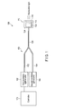
- FIG. 1 The schematic configuration of a light source device 100 according to the present embodiment is shown in FIG. 1 .
- the light source device 100 includes a wavelength converting unit 110, an optical coupler 150, a first excitation light source 162, a second excitation light source 164, and a controller 170.
- the first excitation light source 162 is a light source which generates excitation light having a wavelength in a first wavelength region.
- the central wavelength in the first wavelength region is 450 nm
- the first excitation light source 162 is a blue laser diode (blue LD) which emits laser light having a wavelength of 450 nm.
- the excitation light emitted from the first excitation light source 162 is hereinafter referred to as first excitation light.
- the second excitation light source 164 is a light source which generates excitation light having a wavelength in a second wavelength region.
- the central wavelength in the second wavelength region is 405 nm
- the second excitation light source 164 is a blue-violet laser diode (blue-violet LD) which emits laser light having a wavelength of 405 nm.
- the excitation light emitted from the second excitation light source 164 is hereinafter referred to as second excitation light.
- the controller 170 drives and controls the first excitation light source 162 and the second excitation light source 164. That is, the controller 170 comprises driving circuits which drive the first excitation light source 162 and the second excitation light source 164, respectively. The controller 170 independently controls these driving circuits.
- the controller 170 is capable of continuous driving or pulsed driving of the first excitation light source 162 and the second excitation light source 164.
- the controller 170 can also turn on one of the first excitation light source 162 and the second excitation light source 164, and turn off the other.
- the controller 170 can adjust the ratio between an excitation light intensity of the first excitation light source 162 and an excitation light intensity of the second excitation light source 164 to adjust the color of illumination light, that is, adjust spectrum.
- the optical coupler 150 includes a first optical fiber 152, a second optical fiber 154, and a third optical fiber 156.
- the first optical fiber 152 guides the first excitation light which is the laser light emitted from the first excitation light source 162.
- the second optical fiber 154 guides the second excitation light which is the laser light emitted from the second excitation light source 164.
- the light guide paths of the first optical fiber 152 and the second optical fiber 154 are combined into one. That is, the optical coupler 150 combines the first excitation light and the second excitation light.
- the third optical fiber 156 guides the combined light to the wavelength converting unit 110.
- the wavelength converting unit 110 is a wavelength converting unit which receives the first excitation light and the second excitation light guided by the optical coupler 150 and converts part of the first excitation light and the second excitation light to illumination light having different wavelengths.
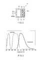
- the general structure of the wavelength converting unit 110 is shown in FIG. 2 .
- the wavelength converting unit 110 includes a first wavelength converting member 112, a second wavelength converting member 114, a light transmitting member 122, and a holder 124.
- the light transmitting member 122, the first wavelength converting member 112, and the second wavelength converting member 114 are held by the holder 124 together with the emission end of the optical coupler 150.
- the holder 124 has, for example, a cylindrical shape.
- the holder 124 holds the emission end of the third optical fiber 156 of the optical coupler 150 by the part of an incidence opening 124-1 at one end of the holder 124.
- the holder 124 has an emission opening 124-2 located opposite to the incidence opening 124-1, and has a continuous through-hole from the incidence opening 124-1 to the emission opening 124-2.
- An unshown reflecting member is formed on the inner side of this through-hole.
- the holder 124 holds the light transmitting member 122, the first wavelength converting member 112, and the second wavelength converting member 114 in order from the emission end of the optical coupler 150 in the emission direction of the excitation light which is emitted from the emission end. Therefore, the excitation light emitted from the emission end of the optical coupler 150 passes through the light transmitting member 122, the first wavelength converting member 112, and the second wavelength converting member 114 in order, and is emitted from the emission opening 124-2 of the holder 124.
- the light transmitting member 122, the first wavelength converting member 112, and the second wavelength converting member 114 each have, for example, a columnar shape with a diameter smaller than the diameter of the through-hole of the holder 124.
- the shape of the holder 124 is cylindrical in the present embodiment, but is not limited to this shape.
- the holder 124 may have such a shape as a circular cone in which the incidence opening is at the top and the emission opening is at the bottom.
- the light transmitting member 122 has the property of transmitting the first excitation light and the second excitation light emitted from the emission end of the optical coupler 150, and the fluorescence emitted from the first wavelength converting member 112 and the second wavelength converting member 114.
- the light transmitting member 122 is made of, for example, glass or a silicone resin having a high transmittance.
- the light transmitting member 122 has a thickness such that the distance from the emission end of the optical coupler 150 to the first wavelength converting member 112 is a desired distance.
- the surface on the side of the light transmitting member 122 is referred to as a light receiving surface
- the surface on the side of the second wavelength converting member 114 is referred to as an emission surface.
- the surface on the side of the first wavelength converting member 112 is referred to as a light receiving surface
- the surface opposite to this light receiving surface is referred to as an emission surface.
- the emission surface of the second wavelength converting member 114 is configured to be flush with the end face of the emission opening 124-2 of the holder 124.
- a fluorescent material having a composition represented by Y 3 Al 5 O 12 :Ce (hereinafter referred to as YAG) is used for the first wavelength converting member 112.
- the first wavelength converting member 112 is made of polycrystallized YAG ceramics.
- YAG ceramics have a property of hardly diffusing transmitted excitation light.
- the absorbed light is wavelength converted, and then isotropically emitted from the first wavelength converting member 112 as fluorescence.
- the excitation light which has not been absorbed in the first wavelength converting member 112 passes through the first wavelength converting member 112.
- the second wavelength converting member 114 includes a fluorescent material 115 and a sealing material 116.
- the fluorescent material 115 is, for example, a powder fluorescent material including (Sr, Ca, Ba, Mg) 10 (PO 4 ) 6 Cl 2 :Eu (hereinafter referred to as SCA).
- SCA powder fluorescent material including (Sr, Ca, Ba, Mg) 10 (PO 4 ) 6 Cl 2 :Eu
- SCA powder fluorescent material including (Sr, Ca, Ba, Mg) 10 (PO 4 ) 6 Cl 2 :Eu
- SCA powder fluorescent material including (Sr, Ca, Ba, Mg) 10 (PO 4 ) 6 Cl 2 :Eu
- SCA powder fluorescent material including (Sr, Ca, Ba, Mg) 10 (PO 4 ) 6 Cl 2 :Eu
- BaMgAl 10 O 17 :Eu or BaMgAl 10 O 17 :Eu,Mn BaMgAl 10 O 17 :Eu,Mn.
- the average particle diameter of the fluorescent material 115 is, for example, 4.5 ⁇ m.
- This fluorescent material 115 is dispersed in the sealing material 116.
- the sealing material 116 is, for example, a transparent resin such as a silicone resin.
- the refractive index of the fluorescent material 115 is higher than the refractive index of the sealing material 116.
- the second wavelength converting member 114 also functions as a diffusing member. That is, part of the excitation light which has entered the second wavelength converting member 114 is absorbed in the powder fluorescent material 115. The absorbed light is wavelength converted, and then emitted from the fluorescent material 115 as fluorescence.
- the fluorescence is isotropically emitted from the fluorescent material 115 in all directions.
- the excitation light which has not been absorbed in the fluorescent material 115 is scattered by the fluorescent material 115 and then emitted from the second wavelength converting member 114 with a predetermined divergence angle.
- the difference between the divergence angle of the light which has entered the second wavelength converting member 114 and the divergence angle of the light emitted from the second wavelength converting member 114, that is, an incremental angle of the divergence angle is determined by, for example, the particle diameter of the fluorescent material 115, the concentration of the fluorescent material 115 compared with the sealing material 116, the refractive indexes of the fluorescent material 115 and the sealing material 116, and the thickness of the whole second wavelength converting member 114.
- the particle diameter of the fluorescent material 115 is preferably about 1/10 of the wavelength of the excitation light to about 1000 times.
- the divergence angle can be increased if the particle diameter of the fluorescent material 115 is between a particle diameter substantially equal to the wavelength of the excitation light and about 100 times the wavelength.
- the concentration of the fluorescent material 115 compared with the sealing material 116 can be widely adjusted, for example, between about 0.1 weight percent and about 70 weight percent.
- the divergence angle is easily adjusted if the concentration of the fluorescent material 115 compared with the sealing material 116 is between 5 weight percent and about 50 weight percent.
- wavelength converting characteristics should preferentially be taken into consideration to select the refractive indexes of the fluorescent material 115 and the sealing material 116.
- the refractive index of the fluorescent material 115 is set to a relatively high value of, for example, 1.7 or more, any transparent resin may be used for the sealing material 116.
- a transparent resin having a refractive index of, for example, 1.5 or less is preferably used for the sealing material 116.
- the difference of refractive index between the fluorescent material 115 and the sealing material 116 is preferably more than about 0.2 because the divergence angle is easily increased.
- a predetermined concentration of a filler which diffuses the excitation light without wavelength conversion may be diffused in the sealing material 116 so that the divergence angle of the excitation light will be a desired angle.
- Absorption/fluorescence characteristics of the first wavelength converting member 112 are shown in FIG. 3 .
- Absorption/fluorescence characteristics of the second wavelength converting member 114 are shown in FIG. 4 .
- broken lines represent the absorption characteristics of the excitation light
- solid lines represent the fluorescence intensity characteristics.
- the first wavelength converting member 112 absorbs the light including the excitation light having a wavelength of 450 nm emitted by the first excitation light source 162, and emits yellow fluorescence having a peak in the vicinity of a wavelength of 550 nm.
- FIG. 3 Absorption/fluorescence characteristics of the first wavelength converting member 112 absorbs the light including the excitation light having a wavelength of 450 nm emitted by the first excitation light source 162, and emits yellow fluorescence having a peak in the vicinity of a wavelength of 550 nm.
- the second wavelength converting member 114 absorbs the light including the excitation light having a wavelength of 405 nm emitted by the second excitation light source 164, and emits blue fluorescence having a peak in the vicinity of a wavelength of 450 nm.
- the controller 170 controls the on/off of the outputs of the first excitation light source 162 and the second excitation light source 164, and their output intensities.
- the first excitation light source 162 emits the first excitation light under the control of the controller 170.
- the second excitation light source 164 emits the second excitation light under the control of the controller 170.
- the first excitation light emitted from the first excitation light source 162 enters the wavelength converting unit 110 through the first optical fiber 152 and the third optical fiber 156 of the optical coupler 150.
- the second excitation light emitted from the second excitation light source 164 enters the wavelength converting unit 110 through the second optical fiber 154 and the third optical fiber 156 of the optical coupler 150.
- the behaviors of the first excitation light and the second excitation light which have entered the wavelength converting unit 110 are described. First described is the case in which the first excitation light emitted from the first excitation light source 162 has entered the wavelength converting unit 110.
- the first excitation light having a wavelength of 450 nm which has passed through the light transmitting member 122 and entered the first wavelength converting member 112 is partly absorbed in the first wavelength converting member 112, as its absorption characteristics are shown in FIG. 3 .
- the wavelength of the first excitation light absorbed in the first wavelength converting member 112 is converted, and yellow fluorescence having a peak in the vicinity of a wavelength of 550 nm is emitted from the first wavelength converting member 112. This yellow fluorescence is hereinafter referred to as first fluorescence.
- the first fluorescence is isotropically emitted from the first wavelength converting member 112 in all directions.
- the second wavelength converting member 114 hardly absorbs the first fluorescence having a peak in the vicinity of a wavelength of 550 nm, as shown by its absorption characteristics in FIG. 4 .
- the first fluorescence which has been emitted from the first wavelength converting member 112 and emitted in a direction other than the direction of the second wavelength converting member 114 is repeatedly reflected on the inner circumferential surface of the holder 124, and again enters the first wavelength converting member 112.
- the first wavelength converting member 112 hardly absorbs the first fluorescence having a peak in the vicinity of a wavelength of 550 nm, as shown in FIG. 3 .
- the first fluorescence passes through the first wavelength converting member 112, and enters the second wavelength converting member 114.
- the first excitation light which is not absorbed in the first wavelength converting member 112 is hardly scattered in the first wavelength converting member 112 and passes through the first wavelength converting member 112 as described above, and then enters the second wavelength converting member 114.
- the second wavelength converting member 114 hardly absorbs the first excitation light having a peak in the vicinity of a wavelength of 450 nm, as shown by its absorption characteristics in FIG. 4 .
- the first fluorescence and the first excitation light which are hardly absorbed in the second wavelength converting member 114 are scattered by the fluorescent material 115 dispersed in the sealing material 116.
- the first fluorescence and the first excitation light which have collided with the inner circumferential surface of the holder 124 are reflected by this inner circumferential surface.
- the first fluorescence and the first excitation light are emitted in various directions from the emission surface of the second wavelength converting member 114. That is, the first fluorescence and the first excitation light are emitted from the wavelength converting unit 110 with a wide divergence angle. In other words, the divergence angles of the first fluorescence and the first excitation light are increased by the second wavelength converting member 114.
- the first fluorescence is emitted from the first wavelength converting member 112 in various directions, and enters the second wavelength converting member 114 from various directions. Therefore, the first fluorescence emitted from the emission surface of the second wavelength converting member 114 has a wide divergence angle.
- the first excitation light is scattered by the second wavelength converting member 114. Therefore, the first excitation light emitted from the emission surface of the second wavelength converting member 114 has a wide divergence angle.
- the particle diameter and concentration of the fluorescent material 115 in the second wavelength converting member 114 are adjusted so that a divergence angle 310 of the first excitation light emitted from the emission surface of the second wavelength converting member 114 is substantially equal to a divergence angle 320 of the first fluorescence, that is, an irradiation region 330 by the first excitation light is substantially equal to an irradiation region 340 by the first fluorescence.
- the first excitation light which has not been absorbed in the first wavelength converting member 112 and has passed through the first wavelength converting member 112 has the highest intensity on its optical axis, and is lower in intensity in peripheral parts.
- the incidence surface of the second wavelength converting member 114 is larger than at least an incidence range of the first excitation light in which the first excitation light that has passed through the first wavelength converting member 112 has a light intensity equal to or more than 1/e times (e is Napier's constant) the intensity on the optical axis. According to this design, most of the first excitation light which has passed through the first wavelength converting member 112 can directly enter the second wavelength converting member 114 through the emission surface of the first wavelength converting member 112.
- the first excitation light source 162 functions as a first excitation light source which emits first excitation light.
- the first wavelength converting member 112 functions as a first optical member which absorbs at least part of the first excitation light, converts the wavelength thereof to emit first wavelength converted light, and increases the divergence angle of the transmitted first excitation light by a first incremental angle.
- the second wavelength converting member 114 functions as a second optical member. The second optical member is disposed in a region including at least an area which includes an optical axis of the first excitation light, light intensity regarding the first excitation light in the area being equal to or more than 1/e times the light intensity on the optical axis of the first excitation light.
- the second optical member increases the divergence angle of the transmitted first excitation light by a second incremental angle larger than the first incremental angle.
- the holder 124 functions as a holding member which holds the first optical member and the second optical member.
- the first wavelength converting member 112 including, for example, the polycrystallized YAG ceramics, the YAG single crystal, or a ceramic fluorescent material such as LAG:Ce or TAG:Ce functions as a first optical member which is a monocrystalline or polycrystalline transparent fluorescent material.
- the second excitation light emitted from the second excitation light source 164 has entered the wavelength converting unit 110.
- the second excitation light having a wavelength of 405 nm which has passed through the light transmitting member 122 and entered the first wavelength converting member 112 is hardly absorbed in the first wavelength converting member 112 as its absorption characteristics are shown in FIG. 3 , and passes through the first wavelength converting member 112.
- the second excitation light is hardly scattered in the first wavelength converting member 112. That is, the second excitation light passes through the first wavelength converting member 112 without changing its divergence angle.
- the second excitation light which has passed through the first wavelength converting member 112 enters the second wavelength converting member 114.
- the second excitation light having a wavelength of 405 nm which has entered the second wavelength converting member 114 is partly absorbed in the second wavelength converting member 114, as shown by its absorption characteristics in FIG. 4 .
- the wavelength of the second excitation light absorbed in the second wavelength converting member 114 is converted, and blue fluorescence having a peak in the vicinity of a wavelength of 450 nm is emitted from the second wavelength converting member 114.
- This blue fluorescence is hereinafter referred to as second fluorescence.
- the second fluorescence is isotropically emitted from the second wavelength converting member 114 in all directions.
- Part of the second fluorescence emitted in the direction of the first wavelength converting member 112 is absorbed in the first wavelength converting member 112, and the above-mentioned first fluorescence is emitted.
- the optical path of this first fluorescence is similar to that in the case described above.
- the second fluorescence which has been emitted in the direction of the first wavelength converting member 112 and passed through the first wavelength converting member 112 without being absorbed therein is reflected by the inner circumferential surface of the holder 124, again enters the first wavelength converting member 112, and is absorbed in the first wavelength converting member 112, and the first fluorescence is emitted, or the second fluorescence passes through the first wavelength converting member 112 and then enters the second wavelength converting member 114.
- the second fluorescence which has been emitted from the second wavelength converting member 114 in the direction of the emission opening is diffused by the fluorescent material 115 dispersed in the sealing material 116.
- the second excitation light which is not absorbed in the second wavelength converting member 114 is also diffused by the fluorescent material 115 dispersed in the sealing material 116.
- the second fluorescence and the second excitation light which have collided with the inner circumferential surface of the holder 124 are reflected by this inner circumferential surface.
- the second fluorescence and the second excitation light are emitted in various directions from the emission surface of the second wavelength converting member 114. That is, the second fluorescence and the second excitation light are emitted from the wavelength converting unit 110 with a wide divergence angle. In other words, the divergence angles of the second fluorescence and the second excitation light are increased by the second wavelength converting member 114.
- the second fluorescence is emitted from the second wavelength converting member 114 in various directions, and has a wide divergence angle.
- the second excitation light is scattered by the second wavelength converting member 114, and has a wide divergence angle.
- the particle diameter and concentration of the fluorescent material 115 in the second wavelength converting member 114 are adjusted so that a divergence angle 360 of the second excitation light emitted from the emission surface of the second wavelength converting member 114 is substantially equal to a divergence angle 370 of the second fluorescence, that is, an irradiation region 380 of the second excitation light is substantially equal to an irradiation region 390 of the second fluorescence.
- the particle diameter and concentration of the fluorescent material 115 in the second wavelength converting member 114 are adjusted so that the divergence angle of the first excitation light emitted from the wavelength converting unit 110 is substantially equal to the divergence angle of the second excitation light emitted from the wavelength converting unit 110.
- the first excitation light, the second excitation light, the first fluorescence and/or the second fluorescence having a divergence angle set as described above are emitted from the emission opening of the wavelength converting unit 110.
- An example spectrum of the light emitted from the wavelength converting unit 110 when both the first excitation light and the second excitation light have entered the wavelength converting unit 110 is shown in FIG. 7 .
- the illumination light spectrum of the light source device 100 is a spectrum including the components of the first excitation light, the second excitation light, the first fluorescence, and the second fluorescence.
- the wavelength converting unit 110 which has the second wavelength converting member 114 located closer to the emission opening than the first wavelength converting member 112, is thus configured so that the absorption of the second excitation light by the first wavelength converting member 112 is reduced and the second excitation light can be emitted with a sufficient intensity.
- the light diffusion by the second wavelength converting member 114 is more than the light diffusion by the first wavelength converting member 112
- the divergence angle 310 of the first excitation light emitted from the wavelength converting unit 110, the divergence angle 360 of the second excitation light, the divergence angle 320 of the first fluorescence, and the divergence angle 370 of the second fluorescence can be equal, so that the light source device 100 can emit illumination light that is less unevenly colored.
- the light diffused by the first wavelength converting member 112 is applied to the inner surface of the holder 124, and light loss through, for example, absorption is greater. Meanwhile, according to the present embodiment, the first wavelength converting member 112 that causes little light diffusion is used. Thus, the energy conversion efficiency of the light source device 100 is high.
- the second wavelength converting member 114 is used to diffuse light as in the present embodiment, it is not necessary to additionally provide a light diffusing member to adjust the divergence angle, and the light loss can be reduced. Consequently, the energy conversion efficiency of the light source device 100 is high.
- the second wavelength converting member 114 and the first wavelength converting member 112 that are fluorescent materials having different absorption/fluorescence characteristics are disposed in the wavelength converting unit 110, and the first excitation light and the second excitation light having two different wavelengths are applied to the second wavelength converting member 114 and the first wavelength converting member 112.
- This configuration permits one light source device to adjust the color of light to be emitted by changing the light intensity ratio between the first excitation light and the second excitation light.
- the difference between the wavelength of the excitation light and the wavelength of the fluorescence is small in the fluorescent materials used for the first wavelength converting member 112 and the second wavelength converting member 114, so that energy loss resulting from wavelength conversion can be reduced. As a result, the energy conversion efficiency of the light source device 100 is higher.
- the sizes of the surfaces of the first wavelength converting member 112 and the second wavelength converting member 114 perpendicular to the optical axes of the first excitation light and the second excitation light are equal to or more than the range in which light having an intensity equal to or more than 1/e times the intensity on the optical axes of the first excitation light and the second excitation light enters, most of the first excitation light and the second excitation light enters.
- the second wavelength converting member 114 includes the fluorescent material which converts the wavelength.
- a dispersing element such as alumina that only has the function to scatter light may be used.
- the first modification is initially described.
- a schematic diagram of the configuration of the wavelength converting unit 110 according to the present modification is shown in FIG. 8 .
- the wavelength converting unit 110 according to the present modification is different from the wavelength converting unit 110 according to the first embodiment in the thickness of the second wavelength converting member 114.
- the second wavelength converting member 114 according to the present modification is thicker on the optical axes of the first excitation light and the second excitation light, and has a convex emission surface.
- the first excitation light and the second excitation light emitted from the emission end of the optical coupler 150 have the strongest light intensity on their optical axes.
- the second wavelength converting member 114 is shaped to be thickest on the optical axes of the first excitation light and the second excitation light, so that the first excitation light and the second excitation light are sufficiently diffused. This shape also allows a higher rate of the wavelength conversion of the second excitation light.
- the emission surface of the second wavelength converting member 114 is projecting outside the emission opening of the holder 124 in FIG. 8 , this is not restrictive.
- the emission surface is convex in the example shown in FIG. 8
- the shape of the second wavelength converting member 114 is not limited to the shape shown in FIG. 8 as long as the second wavelength converting member 114 is thicker in the vicinity of the optical axes than in the circumferential edge.
- the incidence surface may be convex.
- FIG. 9 A schematic diagram of the configuration of the wavelength converting unit 110 according to the present modification is shown in FIG. 9 .
- the wavelength converting unit 110 according to the present modification comprises, on the optical axes of the first excitation light and the second excitation light, the first wavelength converting member 112 smaller in diameter than the second wavelength converting member 114.
- the second wavelength converting member 114 is disposed to also cover the side surface of the first wavelength converting member 112.
- the central part close to the optical axis enters the first wavelength converting member 112, and the circumferential edge part far from the optical axis directly enters the second wavelength converting member 114.
- the second excitation light which has been directly applied to the second wavelength converting member 114 is wavelength converted and is diffused by the second wavelength converting member 114. Some of the second excitation light again enters the first wavelength converting member 112, and the rest passes through the second wavelength converting member 114 and is then emitted from the emission opening of the wavelength converting unit 110.
- the diameter of the first wavelength converting member 112 disposed on the optical axes of the excitation lights is small, so that a lower rate of the second fluorescence which has been wavelength converted from the second excitation light again enters the first wavelength converting member 112.
- the rate of the second fluorescence to be secondarily absorbed in the first wavelength converting member 112 is lower, and the rate of the second fluorescence can be higher.
- FIG. 10 is a schematic diagram showing the cross section of the wavelength converting unit 110.
- FIG. 11 is a schematic diagram showing the plane of the wavelength converting unit 110 seen from the side of the emission opening.
- the second wavelength converting member 114 is disposed on the optical axes of the first excitation light and the second excitation light emitted from the emission end of the optical coupler 150 (the third optical fiber 156).
- the second wavelength converting member 114 is columnar.
- the diameter of the second wavelength converting member 114 is larger than a beam spot diameter at which the first excitation light and the second excitation light enter the second wavelength converting member 114.
- the first wavelength converting member 112 having a hollow and columnar shape is disposed to cover the outer circumferential side surface of the second wavelength converting member 114.
- the first excitation light and the second excitation light emitted from the emission end of the optical coupler 150 pass through the light transmitting member 122, and enter the second wavelength converting member 114.
- the wavelength of some of the second excitation light is converted by the second wavelength converting member 114, and the second fluorescence is emitted.
- the rest of the second excitation light passes through the second wavelength converting member 114 while being scattered therein.
- the first excitation light which has entered the second wavelength converting member 114 is substantially not wavelength converted and is scattered, and is then partly emitted from the emission opening of the wavelength converting unit 110.
- the first excitation light which has been scattered in the second wavelength converting member 114 and then entered the first wavelength converting member 112 is wavelength converted, and the first fluorescence is then emitted.
- the second wavelength converting member 114 having a high ability to diffuse the first excitation light and the second excitation light is located in the region close to the optical axes of the first excitation light and the second excitation light, and the first wavelength converting member 112 having a low diffusing ability is located in the outer circumferential part of the first wavelength converting member 112, so that most of the first excitation light and the second excitation light enter the second wavelength converting member 114.
- the first excitation light and the second excitation light are diffused by the second wavelength converting member 114.
- light having a wide divergence angle can be emitted.
- the first excitation light is wavelength converted by the first wavelength converting member 112 after being diffused by the second wavelength converting member 114. Therefore, places where heat is generated by the wavelength conversion are dispersed, so that it is possible to prevent the first wavelength converting member 112 from being locally increased in temperature. Since the first wavelength converting member 112 and the second wavelength converting member 114 are out of contact with each other on the optical axes of the first excitation light and the second excitation light, the influence of the wavelength conversion loss heat generated in the second wavelength converting member 114 on the first wavelength converting member 112 can be reduced. Consequently, temperature quenching in the first wavelength converting member 112 can be inhibited.
- a third embodiment is described. Here, parts different from those in the first embodiment are described, and the same parts are indicated by the same reference signs and are not described.
- a schematic configuration example of the wavelength converting unit 110 according to the present embodiment is shown in FIG. 12 . As shown in FIG. 12 , the light transmitting member 122, a third wavelength converting member 119, and the second wavelength converting member 114 are arranged in the holder 124 of the wavelength converting unit 110 in order in the traveling direction of the first excitation light and the second excitation light from the side of the emission end of the optical coupler 150.
- the third wavelength converting member 119 has the absorption characteristics for the wavelength region of the first excitation light and the wavelength region of the second excitation light, and emits fluorescence having a peak in the vicinity of a wavelength of 550 nm.
- the fluorescence having the peak in the vicinity of a wavelength of 550 nm is referred to as third fluorescence.
- the material of this third wavelength converting member 119 is, for example, a orthosilicate fluorescent material.
- the third wavelength converting member 119 has a structure in which a powder fluorescent material is dispersed in a sealing material.
- the first excitation light is partly absorbed in the third wavelength converting member 119, and the third fluorescence is isotropically emitted in all directions.
- the third fluorescence is hardly absorbed in the second wavelength converting member 114.
- the third fluorescence is applied to an irradiation region 480 with a wide divergence angle from the emission opening of the wavelength converting unit 110.
- the first excitation light which has passed through the third wavelength converting member 119 is not absorbed in the second wavelength converting member 114, and is diffused in the second wavelength converting member 114, and is then applied to an irradiation region 460 of the first excitation light with a wide divergence angle from the emission opening of the wavelength converting unit 110.
- the second excitation light is partly absorbed in the third wavelength converting member 119, and the third fluorescence is isotropically emitted in all directions.
- the third fluorescence is applied to the irradiation region 480 of the third fluorescence with a wide divergence angle from the emission opening of the wavelength converting unit 110 as described above.
- the second excitation light which has passed through the third wavelength converting member 119 has its wavelength converted by the second wavelength converting member 114, and the second fluorescence is isotropically emitted in all directions.
- the second fluorescence is applied to an irradiation region 470 of the second fluorescence with a wide divergence angle from the emission opening of the wavelength converting unit 110.
- the first excitation light, the second excitation light, the second fluorescence, and the third fluorescence can be emitted from the wavelength converting unit 110 with a properly unified divergence angle.
Landscapes
- Physics & Mathematics (AREA)
- Engineering & Computer Science (AREA)
- General Engineering & Computer Science (AREA)
- Spectroscopy & Molecular Physics (AREA)
- General Physics & Mathematics (AREA)
- Optics & Photonics (AREA)
- Non-Portable Lighting Devices Or Systems Thereof (AREA)
- Semiconductor Lasers (AREA)
- Investigating, Analyzing Materials By Fluorescence Or Luminescence (AREA)
Abstract
Description
- The present invention relates to a light source device.
- In general, there has been developed a light source device which emits light from a small solid-state light source, converts this light by a light converting member, and changes illumination light into a desired irradiation pattern or a desired color. For example, International Publication No.
2008/105527 discloses a light source device which is a combination of an LED chip disposed on a metallic substrate, a sealing resin sealing the LED chip, and a fluorescent material disposed on the sealing resin. In this light source device, a plate-shaped fluorescent material disposed on the LED chip is used to convert the wavelength of part of excitation light emitted from the LED chip and then emit fluorescence. In this way, the technique according to International Publication No.2008/105527 adjusts the illumination light by the excitation light that has passed through the fluorescent material and by the fluorescence emitted from the fluorescent material. - For example, as shown in International Publication No.
2008/105527 , the light source device which adjusts the illumination light by the excitation light that has passed through the fluorescent material and by the fluorescence emitted from the fluorescent material has the following problems. That is, the excitation light passing through the fluorescent material is higher in intensity in the vicinity of an optical axis and lower in intensity at a circumferential edge. In contrast, the fluorescence emitted from the fluorescent material is isotropically scattered, and has an isotropic light intensity. Thus, the illumination light emitted from such a light source device is unevenly colored light having a stronger excitation light component in the center and a weaker fluorescent component at the circumferential edge. - It is therefore an object of the present invention to provide a light source device which emits illumination light having uniform light distribution characteristics.
- To achieve the above described object, according to an aspect of the invention, a light source device is characterized by including a first excitation light source configured to emit first excitation light having a wavelength in a first wavelength region; a first optical member configured to absorb at least part of the first excitation light, convert a wavelength of the part of the first excitation light to emit first wavelength converted light, and increase divergence angle of transmitted first excitation light by a first incremental angle; a second optical member disposed in a region including at least an area which includes an optical axis of the first excitation light, light intensity regarding the first excitation light in the area being equal to or more than 1/e times (e is Napier's constant) light intensity on the optical axis, and the second optical member increasing the divergence angle of the transmitted first excitation light by a second incremental angle larger than the first incremental angle; and a holding member which holds the first optical member and the second optical member.
- According to the present invention, the divergence angle of the excitation light is adjusted by the second optical member, so that it is possible to provide a light source device which emits illumination light having uniform light distribution characteristics.
-
-
FIG. 1 is a block diagram showing a configuration example of a light source device according to a first embodiment of the present invention; -
FIG. 2 is a schematic diagram showing a configuration example of a wavelength converting unit according to the first embodiment; -
FIG. 3 is a graph showing an example of absorption/fluorescence characteristics of a first wavelength converting member according to the first embodiment; -
FIG. 4 is a graph showing an example of absorption/fluorescence characteristics of a second wavelength converting member according to the first embodiment; -
FIG. 5 is a diagram illustrating the divergence angles of first excitation light and first fluorescence that are derived from the first excitation light in the wavelength converting unit according to the first embodiment; -
FIG. 6 is a diagram illustrating the divergence angles of second excitation light and second fluorescence that are derived from the second excitation light in the wavelength converting unit according to the first embodiment; -
FIG. 7 is a graph showing an example of spectral characteristics of illumination light emitted from the wavelength converting unit according to the first embodiment; -
FIG. 8 is a schematic diagram showing a configuration example of the wavelength converting unit according to a first modification of the first embodiment; -
FIG. 9 is a schematic diagram showing a configuration example of the wavelength converting unit according to a second modification of the first embodiment; -
FIG. 10 is a schematic diagram showing a configuration example of the wavelength converting unit according to a second embodiment; -
FIG. 11 is a schematic diagram showing a configuration example of the wavelength converting unit according to the second embodiment; -
FIG. 12 is a diagram illustrating a configuration example of the wavelength converting unit according to a third embodiment, and the divergence angle of illumination light emitted from the wavelength converting unit; and -
FIG. 13 is a graph showing an example of absorption/fluorescence characteristics of a third wavelength converting member according to the third embodiment. - A first embodiment of the present invention is described with reference to the drawings. The schematic configuration of a
light source device 100 according to the present embodiment is shown inFIG. 1 . As shown inFIG. 1 , thelight source device 100 includes awavelength converting unit 110, anoptical coupler 150, a firstexcitation light source 162, a secondexcitation light source 164, and acontroller 170. - The first
excitation light source 162 is a light source which generates excitation light having a wavelength in a first wavelength region. In the present embodiment, the central wavelength in the first wavelength region is 450 nm, and the firstexcitation light source 162 is a blue laser diode (blue LD) which emits laser light having a wavelength of 450 nm. The excitation light emitted from the firstexcitation light source 162 is hereinafter referred to as first excitation light. The secondexcitation light source 164 is a light source which generates excitation light having a wavelength in a second wavelength region. In the present embodiment, the central wavelength in the second wavelength region is 405 nm, and the secondexcitation light source 164 is a blue-violet laser diode (blue-violet LD) which emits laser light having a wavelength of 405 nm. The excitation light emitted from the secondexcitation light source 164 is hereinafter referred to as second excitation light. - The
controller 170 drives and controls the firstexcitation light source 162 and the secondexcitation light source 164. That is, thecontroller 170 comprises driving circuits which drive the firstexcitation light source 162 and the secondexcitation light source 164, respectively. Thecontroller 170 independently controls these driving circuits. Thecontroller 170 is capable of continuous driving or pulsed driving of the firstexcitation light source 162 and the secondexcitation light source 164. Thecontroller 170 can also turn on one of the firstexcitation light source 162 and the secondexcitation light source 164, and turn off the other. Thecontroller 170 can adjust the ratio between an excitation light intensity of the firstexcitation light source 162 and an excitation light intensity of the secondexcitation light source 164 to adjust the color of illumination light, that is, adjust spectrum. - The
optical coupler 150 includes a firstoptical fiber 152, a secondoptical fiber 154, and a thirdoptical fiber 156. The firstoptical fiber 152 guides the first excitation light which is the laser light emitted from the firstexcitation light source 162. The secondoptical fiber 154 guides the second excitation light which is the laser light emitted from the secondexcitation light source 164. The light guide paths of the firstoptical fiber 152 and the secondoptical fiber 154 are combined into one. That is, theoptical coupler 150 combines the first excitation light and the second excitation light. The thirdoptical fiber 156 guides the combined light to thewavelength converting unit 110. - The
wavelength converting unit 110 is a wavelength converting unit which receives the first excitation light and the second excitation light guided by theoptical coupler 150 and converts part of the first excitation light and the second excitation light to illumination light having different wavelengths. The general structure of thewavelength converting unit 110 is shown inFIG. 2 . As shown inFIG. 2 , thewavelength converting unit 110 includes a firstwavelength converting member 112, a secondwavelength converting member 114, alight transmitting member 122, and aholder 124. Thelight transmitting member 122, the firstwavelength converting member 112, and the secondwavelength converting member 114 are held by theholder 124 together with the emission end of theoptical coupler 150. - That is, the
holder 124 has, for example, a cylindrical shape. Theholder 124 holds the emission end of the thirdoptical fiber 156 of theoptical coupler 150 by the part of an incidence opening 124-1 at one end of theholder 124. Theholder 124 has an emission opening 124-2 located opposite to the incidence opening 124-1, and has a continuous through-hole from the incidence opening 124-1 to the emission opening 124-2. An unshown reflecting member is formed on the inner side of this through-hole. - The
holder 124 holds thelight transmitting member 122, the firstwavelength converting member 112, and the secondwavelength converting member 114 in order from the emission end of theoptical coupler 150 in the emission direction of the excitation light which is emitted from the emission end. Therefore, the excitation light emitted from the emission end of theoptical coupler 150 passes through thelight transmitting member 122, the firstwavelength converting member 112, and the secondwavelength converting member 114 in order, and is emitted from the emission opening 124-2 of theholder 124. Thus, thelight transmitting member 122, the firstwavelength converting member 112, and the secondwavelength converting member 114 each have, for example, a columnar shape with a diameter smaller than the diameter of the through-hole of theholder 124. The shape of theholder 124 is cylindrical in the present embodiment, but is not limited to this shape. For example, theholder 124 may have such a shape as a circular cone in which the incidence opening is at the top and the emission opening is at the bottom. - The
light transmitting member 122 has the property of transmitting the first excitation light and the second excitation light emitted from the emission end of theoptical coupler 150, and the fluorescence emitted from the firstwavelength converting member 112 and the secondwavelength converting member 114. Thelight transmitting member 122 is made of, for example, glass or a silicone resin having a high transmittance. In thewavelength converting unit 110, thelight transmitting member 122 has a thickness such that the distance from the emission end of theoptical coupler 150 to the firstwavelength converting member 112 is a desired distance. - In the first
wavelength converting member 112, the surface on the side of thelight transmitting member 122 is referred to as a light receiving surface, and the surface on the side of the secondwavelength converting member 114 is referred to as an emission surface. In the secondwavelength converting member 114, the surface on the side of the firstwavelength converting member 112 is referred to as a light receiving surface, and the surface opposite to this light receiving surface is referred to as an emission surface. The emission surface of the secondwavelength converting member 114 is configured to be flush with the end face of the emission opening 124-2 of theholder 124. - In the present embodiment, for example, a fluorescent material having a composition represented by Y3Al5O12:Ce (hereinafter referred to as YAG) is used for the first
wavelength converting member 112. The firstwavelength converting member 112 is made of polycrystallized YAG ceramics. YAG ceramics have a property of hardly diffusing transmitted excitation light. Instead of YAG ceramics, it is also possible to use YAG single crystal, or a ceramic fluorescent material such as LAG:Ce or TAG:Ce for the firstwavelength converting member 112. Part of the excitation light which has entered the firstwavelength converting member 112 is absorbed in the firstwavelength converting member 112. The absorbed light is wavelength converted, and then isotropically emitted from the firstwavelength converting member 112 as fluorescence. On the other hand, the excitation light which has not been absorbed in the firstwavelength converting member 112 passes through the firstwavelength converting member 112. - The second
wavelength converting member 114 includes afluorescent material 115 and a sealingmaterial 116. Thefluorescent material 115 is, for example, a powder fluorescent material including (Sr, Ca, Ba, Mg)10(PO4)6Cl2:Eu (hereinafter referred to as SCA). Instead of SCA, it is also possible to use, for example, BaMgAl10O17:Eu or BaMgAl10O17:Eu,Mn. - The average particle diameter of the
fluorescent material 115 is, for example, 4.5 µm. Thisfluorescent material 115 is dispersed in the sealingmaterial 116. Here, the sealingmaterial 116 is, for example, a transparent resin such as a silicone resin. The refractive index of thefluorescent material 115 is higher than the refractive index of the sealingmaterial 116. Having the configuration in which thepowder fluorescent material 115 is dispersed in thetransparent sealing material 116, the secondwavelength converting member 114 also functions as a diffusing member. That is, part of the excitation light which has entered the secondwavelength converting member 114 is absorbed in thepowder fluorescent material 115. The absorbed light is wavelength converted, and then emitted from thefluorescent material 115 as fluorescence. Here, the fluorescence is isotropically emitted from thefluorescent material 115 in all directions. On the other hand, the excitation light which has not been absorbed in thefluorescent material 115 is scattered by thefluorescent material 115 and then emitted from the secondwavelength converting member 114 with a predetermined divergence angle. In this case, the difference between the divergence angle of the light which has entered the secondwavelength converting member 114 and the divergence angle of the light emitted from the secondwavelength converting member 114, that is, an incremental angle of the divergence angle is determined by, for example, the particle diameter of thefluorescent material 115, the concentration of thefluorescent material 115 compared with the sealingmaterial 116, the refractive indexes of thefluorescent material 115 and the sealingmaterial 116, and the thickness of the whole secondwavelength converting member 114. - The particle diameter of the
fluorescent material 115 is preferably about 1/10 of the wavelength of the excitation light to about 1000 times. In particular, the divergence angle can be increased if the particle diameter of thefluorescent material 115 is between a particle diameter substantially equal to the wavelength of the excitation light and about 100 times the wavelength. The concentration of thefluorescent material 115 compared with the sealingmaterial 116 can be widely adjusted, for example, between about 0.1 weight percent and about 70 weight percent. For example, when the particle diameter of thefluorescent material 115 is between a particle diameter substantially equal to the wavelength and about 100 times the wavelength, the divergence angle is easily adjusted if the concentration of thefluorescent material 115 compared with the sealingmaterial 116 is between 5 weight percent and about 50 weight percent. - For example, wavelength converting characteristics should preferentially be taken into consideration to select the refractive indexes of the
fluorescent material 115 and the sealingmaterial 116. When the refractive index of thefluorescent material 115 is set to a relatively high value of, for example, 1.7 or more, any transparent resin may be used for the sealingmaterial 116. When the refractive index of thefluorescent material 115 is set to a relatively low value of less than 1.7, a transparent resin having a refractive index of, for example, 1.5 or less is preferably used for the sealingmaterial 116. The difference of refractive index between thefluorescent material 115 and the sealingmaterial 116 is preferably more than about 0.2 because the divergence angle is easily increased. A predetermined concentration of a filler which diffuses the excitation light without wavelength conversion may be diffused in the sealingmaterial 116 so that the divergence angle of the excitation light will be a desired angle. - Absorption/fluorescence characteristics of the first
wavelength converting member 112 are shown inFIG. 3 . Absorption/fluorescence characteristics of the secondwavelength converting member 114 are shown inFIG. 4 . Here, inFIG. 3 andFIG. 4 , broken lines represent the absorption characteristics of the excitation light, and solid lines represent the fluorescence intensity characteristics. As shown inFIG. 3 , the firstwavelength converting member 112 absorbs the light including the excitation light having a wavelength of 450 nm emitted by the firstexcitation light source 162, and emits yellow fluorescence having a peak in the vicinity of a wavelength of 550 nm. On the other hand, as shown inFIG. 4 , the secondwavelength converting member 114 absorbs the light including the excitation light having a wavelength of 405 nm emitted by the secondexcitation light source 164, and emits blue fluorescence having a peak in the vicinity of a wavelength of 450 nm. - The operation of the
light source device 100 according to the present embodiment is described. In accordance with an instruction from a user, thecontroller 170 controls the on/off of the outputs of the firstexcitation light source 162 and the secondexcitation light source 164, and their output intensities. The firstexcitation light source 162 emits the first excitation light under the control of thecontroller 170. The secondexcitation light source 164 emits the second excitation light under the control of thecontroller 170. - The first excitation light emitted from the first
excitation light source 162 enters thewavelength converting unit 110 through the firstoptical fiber 152 and the thirdoptical fiber 156 of theoptical coupler 150. The second excitation light emitted from the secondexcitation light source 164 enters thewavelength converting unit 110 through the secondoptical fiber 154 and the thirdoptical fiber 156 of theoptical coupler 150. - The behaviors of the first excitation light and the second excitation light which have entered the
wavelength converting unit 110 are described. First described is the case in which the first excitation light emitted from the firstexcitation light source 162 has entered thewavelength converting unit 110. The first excitation light having a wavelength of 450 nm which has passed through thelight transmitting member 122 and entered the firstwavelength converting member 112 is partly absorbed in the firstwavelength converting member 112, as its absorption characteristics are shown inFIG. 3 . The wavelength of the first excitation light absorbed in the firstwavelength converting member 112 is converted, and yellow fluorescence having a peak in the vicinity of a wavelength of 550 nm is emitted from the firstwavelength converting member 112. This yellow fluorescence is hereinafter referred to as first fluorescence. The first fluorescence is isotropically emitted from the firstwavelength converting member 112 in all directions. - Part of the first fluorescence enters the second
wavelength converting member 114 through the firstwavelength converting member 112. The secondwavelength converting member 114 hardly absorbs the first fluorescence having a peak in the vicinity of a wavelength of 550 nm, as shown by its absorption characteristics inFIG. 4 . The first fluorescence which has been emitted from the firstwavelength converting member 112 and emitted in a direction other than the direction of the secondwavelength converting member 114 is repeatedly reflected on the inner circumferential surface of theholder 124, and again enters the firstwavelength converting member 112. The firstwavelength converting member 112 hardly absorbs the first fluorescence having a peak in the vicinity of a wavelength of 550 nm, as shown inFIG. 3 . The first fluorescence passes through the firstwavelength converting member 112, and enters the secondwavelength converting member 114. - On the other hand, the first excitation light which is not absorbed in the first
wavelength converting member 112 is hardly scattered in the firstwavelength converting member 112 and passes through the firstwavelength converting member 112 as described above, and then enters the secondwavelength converting member 114. The secondwavelength converting member 114 hardly absorbs the first excitation light having a peak in the vicinity of a wavelength of 450 nm, as shown by its absorption characteristics inFIG. 4 . - The first fluorescence and the first excitation light which are hardly absorbed in the second
wavelength converting member 114 are scattered by thefluorescent material 115 dispersed in the sealingmaterial 116. The first fluorescence and the first excitation light which have collided with the inner circumferential surface of theholder 124 are reflected by this inner circumferential surface. Thus, the first fluorescence and the first excitation light are emitted in various directions from the emission surface of the secondwavelength converting member 114. That is, the first fluorescence and the first excitation light are emitted from thewavelength converting unit 110 with a wide divergence angle. In other words, the divergence angles of the first fluorescence and the first excitation light are increased by the secondwavelength converting member 114. - Here, the first fluorescence is emitted from the first
wavelength converting member 112 in various directions, and enters the secondwavelength converting member 114 from various directions. Therefore, the first fluorescence emitted from the emission surface of the secondwavelength converting member 114 has a wide divergence angle. The first excitation light is scattered by the secondwavelength converting member 114. Therefore, the first excitation light emitted from the emission surface of the secondwavelength converting member 114 has a wide divergence angle. Here, as shown inFIG. 5 , the particle diameter and concentration of thefluorescent material 115 in the secondwavelength converting member 114 are adjusted so that a divergence angle 310 of the first excitation light emitted from the emission surface of the secondwavelength converting member 114 is substantially equal to a divergence angle 320 of the first fluorescence, that is, anirradiation region 330 by the first excitation light is substantially equal to anirradiation region 340 by the first fluorescence. - The first excitation light which has not been absorbed in the first
wavelength converting member 112 and has passed through the firstwavelength converting member 112 has the highest intensity on its optical axis, and is lower in intensity in peripheral parts. Here, the incidence surface of the secondwavelength converting member 114 is larger than at least an incidence range of the first excitation light in which the first excitation light that has passed through the firstwavelength converting member 112 has a light intensity equal to or more than 1/e times (e is Napier's constant) the intensity on the optical axis. According to this design, most of the first excitation light which has passed through the firstwavelength converting member 112 can directly enter the secondwavelength converting member 114 through the emission surface of the firstwavelength converting member 112. - Thus, for example, the first
excitation light source 162 functions as a first excitation light source which emits first excitation light. For example, the firstwavelength converting member 112 functions as a first optical member which absorbs at least part of the first excitation light, converts the wavelength thereof to emit first wavelength converted light, and increases the divergence angle of the transmitted first excitation light by a first incremental angle. For example, the secondwavelength converting member 114 functions as a second optical member. The second optical member is disposed in a region including at least an area which includes an optical axis of the first excitation light, light intensity regarding the first excitation light in the area being equal to or more than 1/e times the light intensity on the optical axis of the first excitation light. The second optical member increases the divergence angle of the transmitted first excitation light by a second incremental angle larger than the first incremental angle. For example, theholder 124 functions as a holding member which holds the first optical member and the second optical member. The firstwavelength converting member 112 including, for example, the polycrystallized YAG ceramics, the YAG single crystal, or a ceramic fluorescent material such as LAG:Ce or TAG:Ce functions as a first optical member which is a monocrystalline or polycrystalline transparent fluorescent material. - Next described is the case in which the second excitation light emitted from the second
excitation light source 164 has entered thewavelength converting unit 110. The second excitation light having a wavelength of 405 nm which has passed through thelight transmitting member 122 and entered the firstwavelength converting member 112 is hardly absorbed in the firstwavelength converting member 112 as its absorption characteristics are shown inFIG. 3 , and passes through the firstwavelength converting member 112. Here, as described above, the second excitation light is hardly scattered in the firstwavelength converting member 112. That is, the second excitation light passes through the firstwavelength converting member 112 without changing its divergence angle. The second excitation light which has passed through the firstwavelength converting member 112 enters the secondwavelength converting member 114. - The second excitation light having a wavelength of 405 nm which has entered the second
wavelength converting member 114 is partly absorbed in the secondwavelength converting member 114, as shown by its absorption characteristics inFIG. 4 . The wavelength of the second excitation light absorbed in the secondwavelength converting member 114 is converted, and blue fluorescence having a peak in the vicinity of a wavelength of 450 nm is emitted from the secondwavelength converting member 114. This blue fluorescence is hereinafter referred to as second fluorescence. The second fluorescence is isotropically emitted from the secondwavelength converting member 114 in all directions. - Part of the second fluorescence emitted in the direction of the first
wavelength converting member 112 is absorbed in the firstwavelength converting member 112, and the above-mentioned first fluorescence is emitted. The optical path of this first fluorescence is similar to that in the case described above. The second fluorescence which has been emitted in the direction of the firstwavelength converting member 112 and passed through the firstwavelength converting member 112 without being absorbed therein is reflected by the inner circumferential surface of theholder 124, again enters the firstwavelength converting member 112, and is absorbed in the firstwavelength converting member 112, and the first fluorescence is emitted, or the second fluorescence passes through the firstwavelength converting member 112 and then enters the secondwavelength converting member 114. - The second fluorescence which has been emitted from the second
wavelength converting member 114 in the direction of the emission opening is diffused by thefluorescent material 115 dispersed in the sealingmaterial 116. The second excitation light which is not absorbed in the secondwavelength converting member 114 is also diffused by thefluorescent material 115 dispersed in the sealingmaterial 116. - The second fluorescence and the second excitation light which have collided with the inner circumferential surface of the
holder 124 are reflected by this inner circumferential surface. Thus, the second fluorescence and the second excitation light are emitted in various directions from the emission surface of the secondwavelength converting member 114. That is, the second fluorescence and the second excitation light are emitted from thewavelength converting unit 110 with a wide divergence angle. In other words, the divergence angles of the second fluorescence and the second excitation light are increased by the secondwavelength converting member 114. - Here, the second fluorescence is emitted from the second
wavelength converting member 114 in various directions, and has a wide divergence angle. The second excitation light is scattered by the secondwavelength converting member 114, and has a wide divergence angle. As shown inFIG. 6 , the particle diameter and concentration of thefluorescent material 115 in the secondwavelength converting member 114 are adjusted so that a divergence angle 360 of the second excitation light emitted from the emission surface of the secondwavelength converting member 114 is substantially equal to a divergence angle 370 of the second fluorescence, that is, anirradiation region 380 of the second excitation light is substantially equal to anirradiation region 390 of the second fluorescence. Moreover, the particle diameter and concentration of thefluorescent material 115 in the secondwavelength converting member 114 are adjusted so that the divergence angle of the first excitation light emitted from thewavelength converting unit 110 is substantially equal to the divergence angle of the second excitation light emitted from thewavelength converting unit 110. - When the first excitation light and/or the second excitation light enter the
wavelength converting unit 110 as described above, the first excitation light, the second excitation light, the first fluorescence and/or the second fluorescence having a divergence angle set as described above are emitted from the emission opening of thewavelength converting unit 110. An example spectrum of the light emitted from thewavelength converting unit 110 when both the first excitation light and the second excitation light have entered thewavelength converting unit 110 is shown inFIG. 7 . As shown inFIG. 7 , the illumination light spectrum of thelight source device 100 is a spectrum including the components of the first excitation light, the second excitation light, the first fluorescence, and the second fluorescence. Thewavelength converting unit 110, which has the secondwavelength converting member 114 located closer to the emission opening than the firstwavelength converting member 112, is thus configured so that the absorption of the second excitation light by the firstwavelength converting member 112 is reduced and the second excitation light can be emitted with a sufficient intensity. - According to the present embodiment, since the light diffusion by the second
wavelength converting member 114 is more than the light diffusion by the firstwavelength converting member 112, it is possible to equally adjust the divergence angle 310 of the first excitation light, the divergence angle 360 of the second excitation light, the divergence angle 320 of the first fluorescence, and the divergence angle 370 of the second fluorescence with ease. The divergence angle 310 of the first excitation light emitted from thewavelength converting unit 110, the divergence angle 360 of the second excitation light, the divergence angle 320 of the first fluorescence, and the divergence angle 370 of the second fluorescence can be equal, so that thelight source device 100 can emit illumination light that is less unevenly colored. - If the light is greatly diffused by the first
wavelength converting member 112, the light diffused by the firstwavelength converting member 112 is applied to the inner surface of theholder 124, and light loss through, for example, absorption is greater. Meanwhile, according to the present embodiment, the firstwavelength converting member 112 that causes little light diffusion is used. Thus, the energy conversion efficiency of thelight source device 100 is high. When the secondwavelength converting member 114 is used to diffuse light as in the present embodiment, it is not necessary to additionally provide a light diffusing member to adjust the divergence angle, and the light loss can be reduced. Consequently, the energy conversion efficiency of thelight source device 100 is high. - In the configuration according to the present embodiment, the second
wavelength converting member 114 and the firstwavelength converting member 112 that are fluorescent materials having different absorption/fluorescence characteristics are disposed in thewavelength converting unit 110, and the first excitation light and the second excitation light having two different wavelengths are applied to the secondwavelength converting member 114 and the firstwavelength converting member 112. This configuration permits one light source device to adjust the color of light to be emitted by changing the light intensity ratio between the first excitation light and the second excitation light. - According to the present embodiment, the difference between the wavelength of the excitation light and the wavelength of the fluorescence is small in the fluorescent materials used for the first
wavelength converting member 112 and the secondwavelength converting member 114, so that energy loss resulting from wavelength conversion can be reduced. As a result, the energy conversion efficiency of thelight source device 100 is higher. - When the sizes of the surfaces of the first
wavelength converting member 112 and the secondwavelength converting member 114 perpendicular to the optical axes of the first excitation light and the second excitation light are equal to or more than the range in which light having an intensity equal to or more than 1/e times the intensity on the optical axes of the first excitation light and the second excitation light enters, most of the first excitation light and the second excitation light enters. - According to the present embodiment described above, the second
wavelength converting member 114 includes the fluorescent material which converts the wavelength. In contrast, when the first excitation light alone is used, a dispersing element such as alumina that only has the function to scatter light may be used. In this case, it is possible to configure a light source device which allows the divergence angles of the first excitation light and the first fluorescence to be the same and thereby emits the first excitation light, the second excitation light, and the first fluorescence that are not unevenly colored. - Modifications of the first embodiment are described. Here, parts different from those in the first embodiment are described, and the same parts are indicated by the same reference signs and are not described. The first modification is initially described. A schematic diagram of the configuration of the
wavelength converting unit 110 according to the present modification is shown inFIG. 8 . As shown inFIG. 8 , thewavelength converting unit 110 according to the present modification is different from thewavelength converting unit 110 according to the first embodiment in the thickness of the secondwavelength converting member 114. The secondwavelength converting member 114 according to the present modification is thicker on the optical axes of the first excitation light and the second excitation light, and has a convex emission surface. - The first excitation light and the second excitation light emitted from the emission end of the optical coupler 150 (the third optical fiber 156) have the strongest light intensity on their optical axes. The second
wavelength converting member 114 is shaped to be thickest on the optical axes of the first excitation light and the second excitation light, so that the first excitation light and the second excitation light are sufficiently diffused. This shape also allows a higher rate of the wavelength conversion of the second excitation light. - Although the emission surface of the second
wavelength converting member 114 is projecting outside the emission opening of theholder 124 inFIG. 8 , this is not restrictive. Although the emission surface is convex in the example shown inFIG. 8 , the shape of the secondwavelength converting member 114 is not limited to the shape shown inFIG. 8 as long as the secondwavelength converting member 114 is thicker in the vicinity of the optical axes than in the circumferential edge. The incidence surface may be convex. - Now, the second modification is described. A schematic diagram of the configuration of the
wavelength converting unit 110 according to the present modification is shown inFIG. 9 . As shown inFIG. 9 , thewavelength converting unit 110 according to the present modification comprises, on the optical axes of the first excitation light and the second excitation light, the firstwavelength converting member 112 smaller in diameter than the secondwavelength converting member 114. The secondwavelength converting member 114 is disposed to also cover the side surface of the firstwavelength converting member 112. - Regarding the second excitation light which has entered with a predetermined divergence angle, the central part close to the optical axis enters the first
wavelength converting member 112, and the circumferential edge part far from the optical axis directly enters the secondwavelength converting member 114. The second excitation light which has been directly applied to the secondwavelength converting member 114 is wavelength converted and is diffused by the secondwavelength converting member 114. Some of the second excitation light again enters the firstwavelength converting member 112, and the rest passes through the secondwavelength converting member 114 and is then emitted from the emission opening of thewavelength converting unit 110. - According to the present modification, the diameter of the first
wavelength converting member 112 disposed on the optical axes of the excitation lights is small, so that a lower rate of the second fluorescence which has been wavelength converted from the second excitation light again enters the firstwavelength converting member 112. As a result, the rate of the second fluorescence to be secondarily absorbed in the firstwavelength converting member 112 is lower, and the rate of the second fluorescence can be higher. - A second embodiment is described. Here, parts different from those in the first embodiment are described, and the same parts are indicated by the same reference signs and are not described. A schematic configuration example of the
wavelength converting unit 110 according to the present embodiment is shown inFIG. 10 and FIG. 11. FIG. 10 is a schematic diagram showing the cross section of thewavelength converting unit 110.FIG. 11 is a schematic diagram showing the plane of thewavelength converting unit 110 seen from the side of the emission opening. - As shown in
FIG. 10 and FIG. 11 , the secondwavelength converting member 114 is disposed on the optical axes of the first excitation light and the second excitation light emitted from the emission end of the optical coupler 150 (the third optical fiber 156). The secondwavelength converting member 114 is columnar. Here, as the divergence angles of the first excitation light and the second excitation light are indicated by broken lines inFIG. 10 , the diameter of the secondwavelength converting member 114 is larger than a beam spot diameter at which the first excitation light and the second excitation light enter the secondwavelength converting member 114. The firstwavelength converting member 112 having a hollow and columnar shape is disposed to cover the outer circumferential side surface of the secondwavelength converting member 114. - The first excitation light and the second excitation light emitted from the emission end of the optical coupler 150 (the third optical fiber 156) pass through the
light transmitting member 122, and enter the secondwavelength converting member 114. The wavelength of some of the second excitation light is converted by the secondwavelength converting member 114, and the second fluorescence is emitted. The rest of the second excitation light passes through the secondwavelength converting member 114 while being scattered therein. On the other hand, the first excitation light which has entered the secondwavelength converting member 114 is substantially not wavelength converted and is scattered, and is then partly emitted from the emission opening of thewavelength converting unit 110. The first excitation light which has been scattered in the secondwavelength converting member 114 and then entered the firstwavelength converting member 112 is wavelength converted, and the first fluorescence is then emitted. - The second
wavelength converting member 114 having a high ability to diffuse the first excitation light and the second excitation light is located in the region close to the optical axes of the first excitation light and the second excitation light, and the firstwavelength converting member 112 having a low diffusing ability is located in the outer circumferential part of the firstwavelength converting member 112, so that most of the first excitation light and the second excitation light enter the secondwavelength converting member 114. As a result, the first excitation light and the second excitation light are diffused by the secondwavelength converting member 114. Thus, according to the present embodiment, light having a wide divergence angle can be emitted. - The first excitation light is wavelength converted by the first
wavelength converting member 112 after being diffused by the secondwavelength converting member 114. Therefore, places where heat is generated by the wavelength conversion are dispersed, so that it is possible to prevent the firstwavelength converting member 112 from being locally increased in temperature. Since the firstwavelength converting member 112 and the secondwavelength converting member 114 are out of contact with each other on the optical axes of the first excitation light and the second excitation light, the influence of the wavelength conversion loss heat generated in the secondwavelength converting member 114 on the firstwavelength converting member 112 can be reduced. Consequently, temperature quenching in the firstwavelength converting member 112 can be inhibited. - A third embodiment is described. Here, parts different from those in the first embodiment are described, and the same parts are indicated by the same reference signs and are not described. A schematic configuration example of the
wavelength converting unit 110 according to the present embodiment is shown inFIG. 12 . As shown inFIG. 12 , thelight transmitting member 122, a thirdwavelength converting member 119, and the secondwavelength converting member 114 are arranged in theholder 124 of thewavelength converting unit 110 in order in the traveling direction of the first excitation light and the second excitation light from the side of the emission end of theoptical coupler 150. - An example of absorption/fluorescence characteristics of the third
wavelength converting member 119 is shown inFIG. 13 . As shown inFIG. 13 , the thirdwavelength converting member 119 has the absorption characteristics for the wavelength region of the first excitation light and the wavelength region of the second excitation light, and emits fluorescence having a peak in the vicinity of a wavelength of 550 nm. Hereinafter, the fluorescence having the peak in the vicinity of a wavelength of 550 nm is referred to as third fluorescence. The material of this thirdwavelength converting member 119 is, for example, a orthosilicate fluorescent material. Although not shown inFIG. 12 , the thirdwavelength converting member 119 has a structure in which a powder fluorescent material is dispersed in a sealing material. - According to the present embodiment, the first excitation light is partly absorbed in the third
wavelength converting member 119, and the third fluorescence is isotropically emitted in all directions. The third fluorescence is hardly absorbed in the secondwavelength converting member 114. Thus, the third fluorescence is applied to anirradiation region 480 with a wide divergence angle from the emission opening of thewavelength converting unit 110. - On the other hand, the first excitation light which has passed through the third
wavelength converting member 119 is not absorbed in the secondwavelength converting member 114, and is diffused in the secondwavelength converting member 114, and is then applied to anirradiation region 460 of the first excitation light with a wide divergence angle from the emission opening of thewavelength converting unit 110. - The second excitation light is partly absorbed in the third
wavelength converting member 119, and the third fluorescence is isotropically emitted in all directions. The third fluorescence is applied to theirradiation region 480 of the third fluorescence with a wide divergence angle from the emission opening of thewavelength converting unit 110 as described above. On the other hand, the second excitation light which has passed through the thirdwavelength converting member 119 has its wavelength converted by the secondwavelength converting member 114, and the second fluorescence is isotropically emitted in all directions. As a result, the second fluorescence is applied to anirradiation region 470 of the second fluorescence with a wide divergence angle from the emission opening of thewavelength converting unit 110. - According to the present embodiment, the first excitation light, the second excitation light, the second fluorescence, and the third fluorescence can be emitted from the
wavelength converting unit 110 with a properly unified divergence angle. - It should be noted that the present invention is not completely limited to the embodiments described above, and modifications of components can be made at the stage of carrying out the invention without departing from the spirit thereof. Further, various inventions can be made by properly combining the components disclosed in the embodiments described above. For example, when the problems described in the section Summary of Invention can be solved and the advantages of the invention can be obtained even if some of all the components shown in the embodiments are eliminated, a configuration in which those components are eliminated can also be extracted as an invention. Moreover, components in different embodiments may be suitably combined together.
Claims (15)
- A light source device (100) characterized by comprising:a first excitation light source (162) configured to emit first excitation light having a wavelength in a first wavelength region;a first optical member (112; 119) configured to absorb at least part of the first excitation light, convert a wavelength of the part of the first excitation light to emit first wavelength converted light, and increase divergence angle of transmitted first excitation light by a first incremental angle;a second optical member (114) disposed in a region including at least an area which includes an optical axis of the first excitation light, light intensity regarding the first excitation light in the area being equal to or more than 1/e times (e is Napier's constant) light intensity on the optical axis, and the second optical member (114) increasing the divergence angle of the transmitted first excitation light by a second incremental angle larger than the first incremental angle; anda holding member (124) which holds the first optical member (112) and the second optical member (114).
- The light source device (100) according to claim 1, characterized in that
the first optical member (112) includes a transparent fluorescent material,
the second optical member (114) includes a powder fluorescent material (115) and a transparent member (116) which transmits light,
the powder fluorescent material (115) absorbs light having a wavelength in a second wavelength region different from the first wavelength region, and converts the wavelength of the light having the wavelength in the second wavelength region to emit second wavelength converted light, and
the powder fluorescent material (115) is dispersed in the transparent member (116). - The light source device (100) according to claim 2, characterized in that
the holding member (124) comprises an incidence portion (124-1) through which the first excitation light enters, and an emission portion (124-2) which emits the first wavelength converted light,
both the first optical member (112) and the second optical member (114) are disposed on the optical axis of the first excitation light entering through the incidence portion (124-1), and
the first optical member (112) is located closer to the incidence portion (124-1) than the second optical member (114). - The light source device (100) according to claim 3, characterized in that a wavelength of the second wavelength converted light is shorter than a wavelength of the first wavelength converted light.
- The light source device (100) according to claim 3 or 4, characterized in that the thickness of the second optical member (114) in an optical axis direction increases towards the optical axis.
- The light source device (100) according to claim 3 or 4, characterized in that
the first optical member (112) and the second optical member (114) are columnar,
a diameter of the second optical member (114) is larger than a diameter of the first optical member (112), and
a thickness of the second optical member (114) in an optical axis direction is greater than a thickness of the first optical member (112) in the optical axis direction. - The light source device (100) according to claim 2, characterized in that
the holding member (124) comprises an incidence portion (124-1) through which the first excitation light enters, and an emission portion (124-2) which emits the first wavelength converted light, and
the first optical member (112) and the second optical member (114) are arranged to divide a surface perpendicular to the optical axis of the first excitation light which enters through the incidence portion (124-1). - The light source device (100) according to claim 7, characterized in that the second optical member (114) alone is disposed on the optical axis of the first excitation light.
- The light source device (100) according to claim 8, characterized in that a surface of the second optical member (114) through which the first excitation light enters is larger than a beam spot diameter of the first excitation light in the surface.
- The light source device (100) according to claim 2, characterized by further comprising a second excitation light source (164) configured to emit second excitation light having a wavelength in a second wavelength region,
wherein the second optical member (114) is configured to absorb at least part of the second excitation light, and convert the wavelength of the second excitation light to emit the second wavelength converted light. - The light source device (100) according to claim 10, characterized in that
the first excitation light and the second excitation light are combined by an optical coupler (150),
the holding member (124) comprises an incidence portion (124-1) through which the first excitation light and the second excitation light that have been combined enter, and an emission portion (124-2) which emits the first excitation light, the second excitation light, the first wavelength converted light, and the second wavelength converted light, and
the optical axis of the first excitation light entering through the incidence portion (124-1) corresponds to an optical axis of the second excitation light. - The light source device (100) according to claim 11, characterized in that
at least one of the first excitation light and the second excitation light pass through the first optical member (112) and the second optical member (114), and are then emitted from the emission portion (124-2), and
the divergence angle of the first excitation light or the second excitation light, the divergence angle of the first wavelength converted light, and the divergence angle of the second wavelength converted light emitted from the emission portion (124-2) are adjusted to be equal to one another. - The light source device (100) according to claim 2, characterized in that the first optical member (112) includes a single crystal or polycrystalline fluorescent material.
- The light source device (100) according to claim 1, characterized in that
the first optical member (119) also absorbs part of light having a wavelength in a second wavelength region different from the first wavelength region, and converts the wavelength of the part of the light having the wavelength in the second wavelength region to emit the first wavelength converted light,
the second optical member (114) includes a powder fluorescent material (115) and a transparent member (116) which transmits light, the powder fluorescent material absorbing the light having the wavelength in the second wavelength region and converting the wavelength of the light having the wavelength in the second wavelength region to emit second wavelength converted light, and
the powder fluorescent material (115) is dispersed in the transparent member (116). - The light source device (100) according to claim 1, characterized in that
the second optical member (114) comprises diffused particles (115), and a transparent member (116) which transmits the first excitation light and the first wavelength converted light,
the diffused particles (115) are dispersed in the transparent member (116), and
the diffused particles (115) includes one ofreflective diffused particles which reflect at least one of the first excitation light and the first wavelength converted light, andtransmissive diffused particles which have a refractive index higher than a refractive index of the transparent member and transmit at least one of the first excitation light and the first wavelength converted light.
Applications Claiming Priority (2)
| Application Number | Priority Date | Filing Date | Title |
|---|---|---|---|
| JP2011224114A JP5830340B2 (en) | 2011-10-11 | 2011-10-11 | Light source device |
| PCT/JP2012/075993 WO2013054763A1 (en) | 2011-10-11 | 2012-10-05 | Light-source device |
Publications (3)
| Publication Number | Publication Date |
|---|---|
| EP2767756A1 true EP2767756A1 (en) | 2014-08-20 |
| EP2767756A4 EP2767756A4 (en) | 2015-07-08 |
| EP2767756B1 EP2767756B1 (en) | 2018-09-26 |
Family
ID=48081818
Family Applications (1)
| Application Number | Title | Priority Date | Filing Date |
|---|---|---|---|
| EP12840415.9A Not-in-force EP2767756B1 (en) | 2011-10-11 | 2012-10-05 | Light-source device |
Country Status (4)
| Country | Link |
|---|---|
| US (1) | US9435513B2 (en) |
| EP (1) | EP2767756B1 (en) |
| JP (1) | JP5830340B2 (en) |
| WO (1) | WO2013054763A1 (en) |
Cited By (2)
| Publication number | Priority date | Publication date | Assignee | Title |
|---|---|---|---|---|
| EP2798263A4 (en) * | 2011-12-22 | 2016-06-08 | Sharp Kk | LASER AND LUMINOPHORES LIGHT SOURCE FOR IMPROVING SAFETY |
| CN108028509A (en) * | 2015-10-28 | 2018-05-11 | 松下知识产权经营株式会社 | Light-emitting device |
Families Citing this family (10)
| Publication number | Priority date | Publication date | Assignee | Title |
|---|---|---|---|---|
| JP2016154063A (en) * | 2013-06-21 | 2016-08-25 | パナソニックIpマネジメント株式会社 | Wavelength conversion member, light source, and lamp |
| US10415780B2 (en) * | 2014-12-02 | 2019-09-17 | Koninklijke Philips N.V. | Laser based lighting system and method |
| JP6538178B2 (en) * | 2015-09-03 | 2019-07-03 | シャープ株式会社 | Light emitting device |
| EP3367141B1 (en) | 2015-10-20 | 2020-12-16 | Panasonic Semiconductor Solutions Co., Ltd. | Wavelength conversion element and light-emitting device |
| CN108368991B (en) * | 2015-12-15 | 2020-06-19 | 飞利浦照明控股有限公司 | Multiple pump glow stick configuration for ultra high brightness |
| JP6469893B2 (en) * | 2016-01-26 | 2019-02-13 | シャープ株式会社 | Light emitting device and lighting device |
| US11011671B2 (en) * | 2018-06-14 | 2021-05-18 | Nichia Corporation | Light emitting device |
| JP2020030047A (en) * | 2018-08-20 | 2020-02-27 | 東海光学株式会社 | Measurement and analysis systems |
| JP6888638B2 (en) * | 2019-01-22 | 2021-06-16 | オムロン株式会社 | Light source device and ranging sensor equipped with it |
| US12191429B2 (en) | 2021-04-08 | 2025-01-07 | Nichia Corporation | Light emitting device |
Family Cites Families (15)
| Publication number | Priority date | Publication date | Assignee | Title |
|---|---|---|---|---|
| US6777871B2 (en) * | 2000-03-31 | 2004-08-17 | General Electric Company | Organic electroluminescent devices with enhanced light extraction |
| US7433115B2 (en) * | 2004-12-15 | 2008-10-07 | Nichia Corporation | Light emitting device |
| JP4608402B2 (en) * | 2005-09-15 | 2011-01-12 | 日本電信電話株式会社 | Wavelength conversion device and fluorescence microscope device |
| WO2007085977A1 (en) | 2006-01-24 | 2007-08-02 | Philips Intellectual Property & Standards Gmbh | Light-emitting device |
| JP4793684B2 (en) * | 2006-03-23 | 2011-10-12 | 日亜化学工業株式会社 | Light emitting device |
| KR100835063B1 (en) * | 2006-10-02 | 2008-06-03 | 삼성전기주식회사 | SURFACE LIGHT SOURCE DEVICE USING LEDs |
| JPWO2008105527A1 (en) | 2007-03-01 | 2010-06-03 | Necライティング株式会社 | LED device and lighting device |
| JP2009153712A (en) * | 2007-12-26 | 2009-07-16 | Olympus Corp | Light source device and endoscope apparatus comprising the same |
| EP2272102B1 (en) * | 2008-03-26 | 2016-06-22 | Panasonic Intellectual Property Management Co., Ltd. | Semiconductor light-emitting apparatus |
| JP2009277734A (en) * | 2008-05-12 | 2009-11-26 | Olympus Corp | Semiconductor light source device |
| JP5284006B2 (en) * | 2008-08-25 | 2013-09-11 | シチズン電子株式会社 | Light emitting device |
| KR100982990B1 (en) * | 2008-09-03 | 2010-09-17 | 삼성엘이디 주식회사 | wavelength conversion plate and light emitting device using the same |
| JP2010287680A (en) * | 2009-06-10 | 2010-12-24 | Mitsubishi Chemicals Corp | Light emitting device |
| JP5519303B2 (en) * | 2010-01-20 | 2014-06-11 | オリンパス株式会社 | Wavelength conversion unit and lighting device including the same |
| US20130094179A1 (en) * | 2011-10-13 | 2013-04-18 | Intematix Corporation | Solid-state light emitting devices with multiple remote wavelength conversion components |
-
2011
- 2011-10-11 JP JP2011224114A patent/JP5830340B2/en not_active Expired - Fee Related
-
2012
- 2012-10-05 WO PCT/JP2012/075993 patent/WO2013054763A1/en not_active Ceased
- 2012-10-05 EP EP12840415.9A patent/EP2767756B1/en not_active Not-in-force
-
2014
- 2014-04-08 US US14/247,705 patent/US9435513B2/en active Active
Cited By (5)
| Publication number | Priority date | Publication date | Assignee | Title |
|---|---|---|---|---|
| EP2798263A4 (en) * | 2011-12-22 | 2016-06-08 | Sharp Kk | LASER AND LUMINOPHORES LIGHT SOURCE FOR IMPROVING SAFETY |
| CN108028509A (en) * | 2015-10-28 | 2018-05-11 | 松下知识产权经营株式会社 | Light-emitting device |
| EP3370309A4 (en) * | 2015-10-28 | 2018-12-19 | Panasonic Intellectual Property Management Co., Ltd. | Light emitting device |
| US10378701B2 (en) | 2015-10-28 | 2019-08-13 | Panasonic Intellectual Property Management Co., Ltd. | Light emitting device |
| US10533713B2 (en) | 2015-10-28 | 2020-01-14 | Panasonic Intellectual Property Management Co., Ltd. | Light emitting device |
Also Published As
| Publication number | Publication date |
|---|---|
| WO2013054763A1 (en) | 2013-04-18 |
| US9435513B2 (en) | 2016-09-06 |
| JP2013084470A (en) | 2013-05-09 |
| JP5830340B2 (en) | 2015-12-09 |
| EP2767756A4 (en) | 2015-07-08 |
| EP2767756B1 (en) | 2018-09-26 |
| US20140218893A1 (en) | 2014-08-07 |
Similar Documents
| Publication | Publication Date | Title |
|---|---|---|
| EP2767756B1 (en) | Light-source device | |
| US9863595B2 (en) | Light-emitting unit with optical plate reflecting excitation light and transmitting fluorescent light, and light-emitting device, illumination device, and vehicle headlight including the unit | |
| US8974089B2 (en) | Light emitting device, illumination device, and vehicle headlamp | |
| US10066809B2 (en) | Light emitting device with optical member for exciting fluorescence, illumination device, and vehicle headlamp having the same | |
| CN103615671B (en) | Light source | |
| US20130329448A1 (en) | Lighting apparatus with phosphor element | |
| JP6424336B2 (en) | Floodlight device | |
| CN102662301B (en) | Light source system and related projection system | |
| JP5722068B2 (en) | Light source device, lighting device and vehicle headlamp | |
| JP2012195253A (en) | Semiconductor light emitting apparatus | |
| JP2019179920A (en) | Light emitting device | |
| JP5519303B2 (en) | Wavelength conversion unit and lighting device including the same | |
| US10527237B2 (en) | Illumination apparatus | |
| JP4689579B2 (en) | Light emitting device | |
| WO2014073237A1 (en) | Solid-state lighting device | |
| KR20140109785A (en) | Lighting device | |
| JP6406800B2 (en) | Light emitting device and light conversion unit | |
| US11384920B2 (en) | Illumination device | |
| US8912717B2 (en) | Illumination device including phosphor element and optical system | |
| US11022277B2 (en) | Wavelength converter and lighting apparatus | |
| CN222773105U (en) | Light source module and lighting device | |
| JP2024524377A (en) | Integrated solid-state light source and phosphor module |
Legal Events
| Date | Code | Title | Description |
|---|---|---|---|
| PUAI | Public reference made under article 153(3) epc to a published international application that has entered the european phase |
Free format text: ORIGINAL CODE: 0009012 |
|
| 17P | Request for examination filed |
Effective date: 20140429 |
|
| AK | Designated contracting states |
Kind code of ref document: A1 Designated state(s): AL AT BE BG CH CY CZ DE DK EE ES FI FR GB GR HR HU IE IS IT LI LT LU LV MC MK MT NL NO PL PT RO RS SE SI SK SM TR |
|
| DAX | Request for extension of the european patent (deleted) | ||
| RA4 | Supplementary search report drawn up and despatched (corrected) |
Effective date: 20150610 |
|
| RIC1 | Information provided on ipc code assigned before grant |
Ipc: F21S 2/00 20060101ALI20150603BHEP Ipc: F21V 9/16 20060101AFI20150603BHEP Ipc: F21Y 101/02 20060101ALI20150603BHEP |
|
| RAP1 | Party data changed (applicant data changed or rights of an application transferred) |
Owner name: OLYMPUS CORPORATION |
|
| REG | Reference to a national code |
Ref country code: DE Ref legal event code: R079 Ref document number: 602012051592 Country of ref document: DE Free format text: PREVIOUS MAIN CLASS: F21V0009160000 Ipc: F21V0009380000 |
|
| RIC1 | Information provided on ipc code assigned before grant |
Ipc: F21S 2/00 20160101ALI20180302BHEP Ipc: F21V 9/40 20180101ALI20180302BHEP Ipc: F21V 9/38 20180101AFI20180302BHEP |
|
| GRAP | Despatch of communication of intention to grant a patent |
Free format text: ORIGINAL CODE: EPIDOSNIGR1 |
|
| INTG | Intention to grant announced |
Effective date: 20180417 |
|
| GRAS | Grant fee paid |
Free format text: ORIGINAL CODE: EPIDOSNIGR3 |
|
| GRAA | (expected) grant |
Free format text: ORIGINAL CODE: 0009210 |
|
| AK | Designated contracting states |
Kind code of ref document: B1 Designated state(s): AL AT BE BG CH CY CZ DE DK EE ES FI FR GB GR HR HU IE IS IT LI LT LU LV MC MK MT NL NO PL PT RO RS SE SI SK SM TR |
|
| REG | Reference to a national code |
Ref country code: GB Ref legal event code: FG4D |
|
| REG | Reference to a national code |
Ref country code: CH Ref legal event code: EP |
|
| REG | Reference to a national code |
Ref country code: AT Ref legal event code: REF Ref document number: 1046446 Country of ref document: AT Kind code of ref document: T Effective date: 20181015 |
|
| REG | Reference to a national code |
Ref country code: IE Ref legal event code: FG4D |
|
| REG | Reference to a national code |
Ref country code: DE Ref legal event code: R096 Ref document number: 602012051592 Country of ref document: DE |
|
| REG | Reference to a national code |
Ref country code: NL Ref legal event code: MP Effective date: 20180926 |
|
| PG25 | Lapsed in a contracting state [announced via postgrant information from national office to epo] |
Ref country code: LT Free format text: LAPSE BECAUSE OF FAILURE TO SUBMIT A TRANSLATION OF THE DESCRIPTION OR TO PAY THE FEE WITHIN THE PRESCRIBED TIME-LIMIT Effective date: 20180926 Ref country code: BG Free format text: LAPSE BECAUSE OF FAILURE TO SUBMIT A TRANSLATION OF THE DESCRIPTION OR TO PAY THE FEE WITHIN THE PRESCRIBED TIME-LIMIT Effective date: 20181226 Ref country code: SE Free format text: LAPSE BECAUSE OF FAILURE TO SUBMIT A TRANSLATION OF THE DESCRIPTION OR TO PAY THE FEE WITHIN THE PRESCRIBED TIME-LIMIT Effective date: 20180926 Ref country code: NO Free format text: LAPSE BECAUSE OF FAILURE TO SUBMIT A TRANSLATION OF THE DESCRIPTION OR TO PAY THE FEE WITHIN THE PRESCRIBED TIME-LIMIT Effective date: 20181226 Ref country code: FI Free format text: LAPSE BECAUSE OF FAILURE TO SUBMIT A TRANSLATION OF THE DESCRIPTION OR TO PAY THE FEE WITHIN THE PRESCRIBED TIME-LIMIT Effective date: 20180926 Ref country code: RS Free format text: LAPSE BECAUSE OF FAILURE TO SUBMIT A TRANSLATION OF THE DESCRIPTION OR TO PAY THE FEE WITHIN THE PRESCRIBED TIME-LIMIT Effective date: 20180926 Ref country code: GR Free format text: LAPSE BECAUSE OF FAILURE TO SUBMIT A TRANSLATION OF THE DESCRIPTION OR TO PAY THE FEE WITHIN THE PRESCRIBED TIME-LIMIT Effective date: 20181227 |
|
| PGFP | Annual fee paid to national office [announced via postgrant information from national office to epo] |
Ref country code: DE Payment date: 20180925 Year of fee payment: 7 |
|
| REG | Reference to a national code |
Ref country code: LT Ref legal event code: MG4D |
|
| PG25 | Lapsed in a contracting state [announced via postgrant information from national office to epo] |
Ref country code: HR Free format text: LAPSE BECAUSE OF FAILURE TO SUBMIT A TRANSLATION OF THE DESCRIPTION OR TO PAY THE FEE WITHIN THE PRESCRIBED TIME-LIMIT Effective date: 20180926 Ref country code: LV Free format text: LAPSE BECAUSE OF FAILURE TO SUBMIT A TRANSLATION OF THE DESCRIPTION OR TO PAY THE FEE WITHIN THE PRESCRIBED TIME-LIMIT Effective date: 20180926 Ref country code: AL Free format text: LAPSE BECAUSE OF FAILURE TO SUBMIT A TRANSLATION OF THE DESCRIPTION OR TO PAY THE FEE WITHIN THE PRESCRIBED TIME-LIMIT Effective date: 20180926 |
|
| REG | Reference to a national code |
Ref country code: AT Ref legal event code: MK05 Ref document number: 1046446 Country of ref document: AT Kind code of ref document: T Effective date: 20180926 |
|
| PG25 | Lapsed in a contracting state [announced via postgrant information from national office to epo] |
Ref country code: ES Free format text: LAPSE BECAUSE OF FAILURE TO SUBMIT A TRANSLATION OF THE DESCRIPTION OR TO PAY THE FEE WITHIN THE PRESCRIBED TIME-LIMIT Effective date: 20180926 Ref country code: NL Free format text: LAPSE BECAUSE OF FAILURE TO SUBMIT A TRANSLATION OF THE DESCRIPTION OR TO PAY THE FEE WITHIN THE PRESCRIBED TIME-LIMIT Effective date: 20180926 Ref country code: AT Free format text: LAPSE BECAUSE OF FAILURE TO SUBMIT A TRANSLATION OF THE DESCRIPTION OR TO PAY THE FEE WITHIN THE PRESCRIBED TIME-LIMIT Effective date: 20180926 Ref country code: IT Free format text: LAPSE BECAUSE OF FAILURE TO SUBMIT A TRANSLATION OF THE DESCRIPTION OR TO PAY THE FEE WITHIN THE PRESCRIBED TIME-LIMIT Effective date: 20180926 Ref country code: EE Free format text: LAPSE BECAUSE OF FAILURE TO SUBMIT A TRANSLATION OF THE DESCRIPTION OR TO PAY THE FEE WITHIN THE PRESCRIBED TIME-LIMIT Effective date: 20180926 Ref country code: RO Free format text: LAPSE BECAUSE OF FAILURE TO SUBMIT A TRANSLATION OF THE DESCRIPTION OR TO PAY THE FEE WITHIN THE PRESCRIBED TIME-LIMIT Effective date: 20180926 Ref country code: CZ Free format text: LAPSE BECAUSE OF FAILURE TO SUBMIT A TRANSLATION OF THE DESCRIPTION OR TO PAY THE FEE WITHIN THE PRESCRIBED TIME-LIMIT Effective date: 20180926 Ref country code: IS Free format text: LAPSE BECAUSE OF FAILURE TO SUBMIT A TRANSLATION OF THE DESCRIPTION OR TO PAY THE FEE WITHIN THE PRESCRIBED TIME-LIMIT Effective date: 20190126 Ref country code: PL Free format text: LAPSE BECAUSE OF FAILURE TO SUBMIT A TRANSLATION OF THE DESCRIPTION OR TO PAY THE FEE WITHIN THE PRESCRIBED TIME-LIMIT Effective date: 20180926 |
|
| PG25 | Lapsed in a contracting state [announced via postgrant information from national office to epo] |
Ref country code: PT Free format text: LAPSE BECAUSE OF FAILURE TO SUBMIT A TRANSLATION OF THE DESCRIPTION OR TO PAY THE FEE WITHIN THE PRESCRIBED TIME-LIMIT Effective date: 20190126 Ref country code: SK Free format text: LAPSE BECAUSE OF FAILURE TO SUBMIT A TRANSLATION OF THE DESCRIPTION OR TO PAY THE FEE WITHIN THE PRESCRIBED TIME-LIMIT Effective date: 20180926 Ref country code: SM Free format text: LAPSE BECAUSE OF FAILURE TO SUBMIT A TRANSLATION OF THE DESCRIPTION OR TO PAY THE FEE WITHIN THE PRESCRIBED TIME-LIMIT Effective date: 20180926 |
|
| REG | Reference to a national code |
Ref country code: CH Ref legal event code: PL |
|
| REG | Reference to a national code |
Ref country code: BE Ref legal event code: MM Effective date: 20181031 |
|
| REG | Reference to a national code |
Ref country code: DE Ref legal event code: R097 Ref document number: 602012051592 Country of ref document: DE |
|
| PG25 | Lapsed in a contracting state [announced via postgrant information from national office to epo] |
Ref country code: LU Free format text: LAPSE BECAUSE OF NON-PAYMENT OF DUE FEES Effective date: 20181005 |
|
| REG | Reference to a national code |
Ref country code: IE Ref legal event code: MM4A |
|
| PG25 | Lapsed in a contracting state [announced via postgrant information from national office to epo] |
Ref country code: MC Free format text: LAPSE BECAUSE OF FAILURE TO SUBMIT A TRANSLATION OF THE DESCRIPTION OR TO PAY THE FEE WITHIN THE PRESCRIBED TIME-LIMIT Effective date: 20180926 Ref country code: DK Free format text: LAPSE BECAUSE OF FAILURE TO SUBMIT A TRANSLATION OF THE DESCRIPTION OR TO PAY THE FEE WITHIN THE PRESCRIBED TIME-LIMIT Effective date: 20180926 |
|
| PLBE | No opposition filed within time limit |
Free format text: ORIGINAL CODE: 0009261 |
|
| STAA | Information on the status of an ep patent application or granted ep patent |
Free format text: STATUS: NO OPPOSITION FILED WITHIN TIME LIMIT |
|
| GBPC | Gb: european patent ceased through non-payment of renewal fee |
Effective date: 20181226 |
|
| PG25 | Lapsed in a contracting state [announced via postgrant information from national office to epo] |
Ref country code: LI Free format text: LAPSE BECAUSE OF NON-PAYMENT OF DUE FEES Effective date: 20181031 Ref country code: CH Free format text: LAPSE BECAUSE OF NON-PAYMENT OF DUE FEES Effective date: 20181031 Ref country code: BE Free format text: LAPSE BECAUSE OF NON-PAYMENT OF DUE FEES Effective date: 20181031 |
|
| 26N | No opposition filed |
Effective date: 20190627 |
|
| PG25 | Lapsed in a contracting state [announced via postgrant information from national office to epo] |
Ref country code: SI Free format text: LAPSE BECAUSE OF FAILURE TO SUBMIT A TRANSLATION OF THE DESCRIPTION OR TO PAY THE FEE WITHIN THE PRESCRIBED TIME-LIMIT Effective date: 20180926 Ref country code: IE Free format text: LAPSE BECAUSE OF NON-PAYMENT OF DUE FEES Effective date: 20181005 Ref country code: FR Free format text: LAPSE BECAUSE OF NON-PAYMENT OF DUE FEES Effective date: 20181126 |
|
| PG25 | Lapsed in a contracting state [announced via postgrant information from national office to epo] |
Ref country code: GB Free format text: LAPSE BECAUSE OF NON-PAYMENT OF DUE FEES Effective date: 20181226 |
|
| PG25 | Lapsed in a contracting state [announced via postgrant information from national office to epo] |
Ref country code: MT Free format text: LAPSE BECAUSE OF NON-PAYMENT OF DUE FEES Effective date: 20181005 |
|
| PG25 | Lapsed in a contracting state [announced via postgrant information from national office to epo] |
Ref country code: TR Free format text: LAPSE BECAUSE OF FAILURE TO SUBMIT A TRANSLATION OF THE DESCRIPTION OR TO PAY THE FEE WITHIN THE PRESCRIBED TIME-LIMIT Effective date: 20180926 |
|
| REG | Reference to a national code |
Ref country code: DE Ref legal event code: R119 Ref document number: 602012051592 Country of ref document: DE |
|
| PG25 | Lapsed in a contracting state [announced via postgrant information from national office to epo] |
Ref country code: MK Free format text: LAPSE BECAUSE OF NON-PAYMENT OF DUE FEES Effective date: 20180926 Ref country code: HU Free format text: LAPSE BECAUSE OF FAILURE TO SUBMIT A TRANSLATION OF THE DESCRIPTION OR TO PAY THE FEE WITHIN THE PRESCRIBED TIME-LIMIT; INVALID AB INITIO Effective date: 20121005 Ref country code: CY Free format text: LAPSE BECAUSE OF FAILURE TO SUBMIT A TRANSLATION OF THE DESCRIPTION OR TO PAY THE FEE WITHIN THE PRESCRIBED TIME-LIMIT Effective date: 20180926 |
|
| PG25 | Lapsed in a contracting state [announced via postgrant information from national office to epo] |
Ref country code: DE Free format text: LAPSE BECAUSE OF NON-PAYMENT OF DUE FEES Effective date: 20200501 |