EP2767724B2 - Drive power transmission system - Google Patents
Drive power transmission system Download PDFInfo
- Publication number
- EP2767724B2 EP2767724B2 EP12840119.7A EP12840119A EP2767724B2 EP 2767724 B2 EP2767724 B2 EP 2767724B2 EP 12840119 A EP12840119 A EP 12840119A EP 2767724 B2 EP2767724 B2 EP 2767724B2
- Authority
- EP
- European Patent Office
- Prior art keywords
- clutch
- external air
- plate
- drive power
- hole
- Prior art date
- Legal status (The legal status is an assumption and is not a legal conclusion. Google has not performed a legal analysis and makes no representation as to the accuracy of the status listed.)
- Active
Links
Images


Classifications
-
- F—MECHANICAL ENGINEERING; LIGHTING; HEATING; WEAPONS; BLASTING
- F16—ENGINEERING ELEMENTS AND UNITS; GENERAL MEASURES FOR PRODUCING AND MAINTAINING EFFECTIVE FUNCTIONING OF MACHINES OR INSTALLATIONS; THERMAL INSULATION IN GENERAL
- F16D—COUPLINGS FOR TRANSMITTING ROTATION; CLUTCHES; BRAKES
- F16D25/00—Fluid-actuated clutches
- F16D25/12—Details not specific to one of the before-mentioned types
- F16D25/123—Details not specific to one of the before-mentioned types in view of cooling and lubrication
-
- F—MECHANICAL ENGINEERING; LIGHTING; HEATING; WEAPONS; BLASTING
- F16—ENGINEERING ELEMENTS AND UNITS; GENERAL MEASURES FOR PRODUCING AND MAINTAINING EFFECTIVE FUNCTIONING OF MACHINES OR INSTALLATIONS; THERMAL INSULATION IN GENERAL
- F16D—COUPLINGS FOR TRANSMITTING ROTATION; CLUTCHES; BRAKES
- F16D13/00—Friction clutches
- F16D13/22—Friction clutches with axially-movable clutching members
- F16D13/38—Friction clutches with axially-movable clutching members with flat clutching surfaces, e.g. discs
- F16D13/52—Clutches with multiple lamellae ; Clutches in which three or more axially moveable members are fixed alternately to the shafts to be coupled and are pressed from one side towards an axially-located member
-
- F—MECHANICAL ENGINEERING; LIGHTING; HEATING; WEAPONS; BLASTING
- F16—ENGINEERING ELEMENTS AND UNITS; GENERAL MEASURES FOR PRODUCING AND MAINTAINING EFFECTIVE FUNCTIONING OF MACHINES OR INSTALLATIONS; THERMAL INSULATION IN GENERAL
- F16D—COUPLINGS FOR TRANSMITTING ROTATION; CLUTCHES; BRAKES
- F16D13/00—Friction clutches
- F16D13/58—Details
- F16D13/60—Clutching elements
- F16D13/64—Clutch-plates; Clutch-lamellae
- F16D13/648—Clutch-plates; Clutch-lamellae for clutches with multiple lamellae
-
- F—MECHANICAL ENGINEERING; LIGHTING; HEATING; WEAPONS; BLASTING
- F16—ENGINEERING ELEMENTS AND UNITS; GENERAL MEASURES FOR PRODUCING AND MAINTAINING EFFECTIVE FUNCTIONING OF MACHINES OR INSTALLATIONS; THERMAL INSULATION IN GENERAL
- F16D—COUPLINGS FOR TRANSMITTING ROTATION; CLUTCHES; BRAKES
- F16D25/00—Fluid-actuated clutches
- F16D25/06—Fluid-actuated clutches in which the fluid actuates a piston incorporated in, i.e. rotating with the clutch
- F16D25/062—Fluid-actuated clutches in which the fluid actuates a piston incorporated in, i.e. rotating with the clutch the clutch having friction surfaces
- F16D25/063—Fluid-actuated clutches in which the fluid actuates a piston incorporated in, i.e. rotating with the clutch the clutch having friction surfaces with clutch members exclusively moving axially
- F16D25/0635—Fluid-actuated clutches in which the fluid actuates a piston incorporated in, i.e. rotating with the clutch the clutch having friction surfaces with clutch members exclusively moving axially with flat friction surfaces, e.g. discs
- F16D25/0638—Fluid-actuated clutches in which the fluid actuates a piston incorporated in, i.e. rotating with the clutch the clutch having friction surfaces with clutch members exclusively moving axially with flat friction surfaces, e.g. discs with more than two discs, e.g. multiple lamellae
-
- F—MECHANICAL ENGINEERING; LIGHTING; HEATING; WEAPONS; BLASTING
- F16—ENGINEERING ELEMENTS AND UNITS; GENERAL MEASURES FOR PRODUCING AND MAINTAINING EFFECTIVE FUNCTIONING OF MACHINES OR INSTALLATIONS; THERMAL INSULATION IN GENERAL
- F16D—COUPLINGS FOR TRANSMITTING ROTATION; CLUTCHES; BRAKES
- F16D2300/00—Special features for couplings or clutches
- F16D2300/02—Overheat protection, i.e. means for protection against overheating
- F16D2300/021—Cooling features not provided for in group F16D13/72 or F16D25/123, e.g. heat transfer details
- F16D2300/0212—Air cooling
-
- F—MECHANICAL ENGINEERING; LIGHTING; HEATING; WEAPONS; BLASTING
- F16—ENGINEERING ELEMENTS AND UNITS; GENERAL MEASURES FOR PRODUCING AND MAINTAINING EFFECTIVE FUNCTIONING OF MACHINES OR INSTALLATIONS; THERMAL INSULATION IN GENERAL
- F16D—COUPLINGS FOR TRANSMITTING ROTATION; CLUTCHES; BRAKES
- F16D2300/00—Special features for couplings or clutches
- F16D2300/26—Cover or bell housings; Details or arrangements thereof
-
- F—MECHANICAL ENGINEERING; LIGHTING; HEATING; WEAPONS; BLASTING
- F16—ENGINEERING ELEMENTS AND UNITS; GENERAL MEASURES FOR PRODUCING AND MAINTAINING EFFECTIVE FUNCTIONING OF MACHINES OR INSTALLATIONS; THERMAL INSULATION IN GENERAL
- F16D—COUPLINGS FOR TRANSMITTING ROTATION; CLUTCHES; BRAKES
- F16D25/00—Fluid-actuated clutches
- F16D25/08—Fluid-actuated clutches with fluid-actuated member not rotating with a clutching member
- F16D25/082—Fluid-actuated clutches with fluid-actuated member not rotating with a clutching member the line of action of the fluid-actuated members co-inciding with the axis of rotation
- F16D25/083—Actuators therefor
Definitions
- the present invention relates to a drive power transmission system that is suitable for automobile drive systems in which a dry clutch that disconnects the transmitting of drive power is installed in a sealed space.
- hybrid drive power transmission systems have been known in which the engine, the motor and clutch unit, and the accelerator unit are in a linked connection.
- a dry multi-plate clutch is disposed inside the electric motor.
- a clutch hub that is linked to the output shaft of the engine, a clutch drum to which a rotor of an electric motor is fixed, and which is linked to the input shaft of the transmission, and a dry multi-plate clutch that is interposed between the clutch hub and clutch drum are provided (e.g., refer to patent document 1).
- a drive power transmission system according to the preamble portion of claim 1 is known from patent document 2.
- Another drive power transmission system is known from patent document 3.
- a dry multi-plate clutch is housed in a dry space that is covered by a unit housing and sealed by a sealing member. For this reason, abrasion dust from the friction facing that is produced with repeated engagement and release of the clutch is not discharged and poor engagement and release of the dry multi-plate clutch arises as a result dragging due to the abrasion dust that has accumulated between the friction surfaces.
- the electric motor or clutch is thus disposed in the radial direction of the dry multi-plate clutch, and there is no space to provide abrasion dust discharge openings. There has thus been the problem that abrasion dust cannot be discharged radially.
- the present invention focuses on the above problem, it being an object of the invention to provide a drive power transmission system whereby abrasion dust that is generated between clutch plates that are pressed together via a friction facing can escape outwards by being carried in an axial air flow.
- the present invention is a drive power transmission system in which a dry clutch that disconnects the transmitting of drive power is disposed in a sealed space.
- the dry clutch is means that has a first clutch plate, a second clutch plate, a friction facing, and a cover member.
- the first clutch plate is joined by splines with a clutch hub.
- the second clutch plate is joined by splines with a clutch drum.
- the friction facing is provided on one of the first and second clutch plates, and a friction surface presses against the other plate face during clutch engagement.
- the cover member has an external air intake hole through which external air is taken into the sealed space and an external air discharge hole through which air flow is discharged from inside the sealed space to external air.
- the external air intake hole is provided so that the cover member disposed on a side face of the dry clutch is axially passed through radially inwardly from the two clutch plates.
- the external air discharge hole is provided so that the cover member disposed on a side face of the dry clutch is axially passed through radially outwardly from the two clutch plates.
- the cover member that is disposed on a side face of the dry clutch has an external air intake hole through which external air is taken into the sealed space and an external air discharge hole through which an air flow from the sealed space is discharged into external air.
- a configuration is adopted in which the external air intake hole is provided radially inwardly from the two clutch plates, and the external air discharge hole is provided radially outwardly from the two clutch plates.
- the radially inward pressure of the dry clutch is lower than atmosphere pressure (negative pressure), and the radially outward pressure of the dry clutch is higher than atmospheric pressure (positive pressure), thereby producing a pressure relationship in which the radially-outward clutch air pressure is greater than atmospheric pressure, which is greater than the radially-inward clutch air pressure.
- abrasion dust that has been released from the surface of the friction facing is transferred by being carried along by a series of air flows resulting from the axial intake air flow, the radial air flow and the axial discharge air flow, thereby being externally discharged.
- the abrasion dust that arises between the clutch plates that are pressed together via friction facing can be externally discharged by being carried by a radial air flow.
- Embodiment 1 The configuration of the hybrid drive power transmission system of Embodiment 1 is described below under the headings: General configuration, Motor and clutch unit configuration, Dry multi-plate clutch configuration, and Air flow effect abrasion dust discharge configuration.
- Figure 1 is a general schematic diagram showing the hybrid drive power transmission system of Embodiment 1 (example of drive power transmission system). The general configuration of the device is described below with reference to Figure 1 .
- the hybrid drive power transmission system of Embodiment 1 comprises an engine Eng, a motor and clutch unit M/C, an transmission unit T/M, an engine output shaft 1, a clutch hub shaft 2, a clutch hub 3, a clutch drum shaft 4, a transmission input shaft 5, a clutch drum 6, a dry multi-plate clutch 7 (dry clutch), a slave cylinder 8, and a motor/generator 9.
- the slave cylinder 8 that controls oil pressure that engages and releases the dry multi-plate clutch 7 is generally referred to as a "concentric slave cylinder” (CSC).
- CSC concentric slave cylinder
- the motor and clutch unit M/C has a dry multi-plate clutch 7, a slave cylinder 8, and a motor/generator 9.
- the dry multi-plate clutch 7 is linked and connected to the engine Eng and disconnects the transmitting of drive power from the engine Eng.
- the slave cylinder 8 controls the oil pressure for engaging and releasing the dry multi-plate clutch 7.
- the motor/generator 9 is disposed at an outer circumferential location on the clutch drum 6 of the dry multi-plate clutch 7 and transfers power to the transmission input shaft 5.
- a cylinder housing 81 that has a first clutch hydraulic path 85 is provided on the slave cylinder 8, with a seal maintained by an O-ring 10.
- the motor/generator 9 has a rotor support frame 91 that is integrated with the clutch drum 6 and a rotor 92 enclosing a permanent magnet that is fixed and supported on the rotor support frame 91.
- a stator 94 that is fixed on the cylinder housing 81 and is disposed at the rotor 92 with an air gap 93 interposed, and a stator coil 95 that is wound around the stator 94.
- a water jacket 96 that allows flow of cooling water is formed in the cylinder housing 81.
- the transmission unit T/M is linked and connected to the motor and clutch unit M/C and has a transmission housing 41, a V-belt stepless transmission mechanism 42, and an oil pump O/P.
- the V-belt stepless transmission mechanism 42 is housed in the transmission housing 41, with the V-belt suspended between two pulleys, providing a stepless variable gear ratio by varying the belt contact diameter.
- the oil pump O/P is a hydraulic oil source that provides hydraulic pressure to the required components. With the oil pump pressure as the source pressure, hydraulic pressure is conducted to the required components from a control valve not shown in the drawings that modulates the pressure, e.g., the transmission hydraulic pressure, that is provided to the pulley chamber or the clutch/brake hydraulic pressure.
- This transmission unit T/M also has a forward/reverse switching mechanism 43, an oil tank 44, and an end plate 45.
- the end plate 45 has a second clutch hydraulic path 47 ( Figure 2 ).
- the oil pump O/P is driven as a result of transfer of rotational drive torque from the transmission input shaft 5 via a chain drive mechanism.
- the chain drive mechanism has a drive-side sprocket 51 that rotates along with rotational drive of the transmission input shaft 5, a driven-side sprocket 52 that rotationally drives a pump shaft 57, and a chain 53 that is suspended on both sprockets 51, 52.
- the drive-side sprocket 51 is mounted between the transmission input shaft 5 and an end plate 45 and is rotatably supported via a brush 55 on a stator shaft 54 that is fixed to the transmission housing 41.
- a first adaptor 56 that fits via teeth on the drive-side sprocket 51.
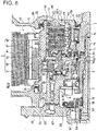
- Figure 2 is a specific sectional view showing the configuration of the motor and clutch unit in the hybrid drive power transmission system of Embodiment 1.
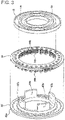
- Figure 3 is an exploded oblique view of the piston assembly of the dry multi-plate clutch in the hybrid drive power transmission system of Embodiment 1. The configuration of the motor and clutch unit M/C is described below with reference to Figures 2 and 3 .
- the clutch hub 3 is linked to the engine output shaft 1 of the engine Eng. As shown in Figure 2 , in the clutch hub 3, a drive plate 71 (first clutch plate) of the dry multi-plate clutch 7 is held by splined joining.
- the clutch drum 6 is linked to the transmission input shaft 5 of the transmission unit T/M. As shown in Figure 2 , a driven plate 72 (second clutch plate) of the dry multi-plate clutch 7 is held by splined joining on this clutch drum 6.
- the drive plate 71 and the driven plate 72 to which friction facings 73, 73 are adhered on both surfaces are interposed alternately between the clutch hub 3 and the clutch drum 6 so that they are aligned in multiple plates.
- torque transfer between the clutch hub 3 and the clutch drum 6 is enabled, and by release of the dry multi-plate clutch 7, torque transfer between the clutch hub 3 and the clutch drum 6 is disconnected.
- the slave cylinder 8 is a hydraulic pressure actuator that controls engagement and release of the dry multi-plate clutch 7 and is disposed at a location that is between the transmission unit T/M and the clutch drum 6.
- the slave cylinder 8 has a piston 82 that is slidably provided in a cylinder hole 80 of the cylinder housing 81, a first clutch hydraulic path 85 that is formed in the cylinder housing 81 and conducts clutch pressure output by the transmission unit T/M, and a cylinder oil housing 86 that communicates with the first clutch hydraulic path 85.
- a needle bearing 87, a piston arm 83, a return spring 84, and an arm press-plate 88 are interposed between the piston 82 and the dry multi-plate clutch 7.
- the piston arm 83 generates press force for the dry multi-plate clutch 7 as a result of the press force from the slave cylinder 8, and the piston arm is slidably provided in a through-hole 61 formed in the clutch drum 6.
- the return spring 84 is interposed between the piston arm 83 and the clutch drum 6.
- the needle bearing 87 is interposed between the piston 82 and the piston arm 83, and the piston 82 suppresses inducement of rotation that occurs along with rotation of the piston arm 83.
- the arm press-plate 88 is provided integrally with elastic bellows-shaped support members 89, 89, and an inner circumferential part and outer circumferential part of the elastic bellows-shaped support members 89, 89 are pressed in and fixed on the clutch drum 6.
- the piston arm 83 comprises an arm body 83a that is formed in the shape of a ring and arm protrusion ridges 83b that protrude from the arm body 83a in four locations.
- the return spring 84 comprises a spring support plate 84a that is formed in the shape of a ring, and multiple coil springs 84b that are fixed on the spring support plate 84a.
- the arm press-plate 88 is pressed and fixed on the arm protrusion ridges 83b of the piston arm 83.
- the bellows-shaped elastic support members 89, 89 are present integrally on the inside and outside of the arm press-plate 88.
- the leak oil recovery path in Embodiment 1, as shown in Figure 2 comprises a first bearing 12, a first seal member 31, a leak oil path 32, a first recovery oil path 33, and a second recovery oil path 34.
- the path is a circuit whereby leak oil from the sliding part of the piston 82 passes through the first recovery oil path 33 and the second recovery oil path 34 that are sealed by a first seal member 31 and then returns to the transmission unit T/M.
- the path is a circuit whereby leak oil from the sliding part of the piston arm 83 passes through the leak oil path 32 that is sealed by the partitioning elastic members (arm press-plate 88, bellows-shaped elastic support member 89, 89) and the first recovery oil path 33 and second recovery oil path 34 that are sealed by the first seal member 31 and then returns to the transmission unit T/M.
- the partitioning elastic members arm press-plate 88, bellows-shaped elastic support member 89, 89
- the bearing lubricating oil path of Embodiment 1, as shown in Figure 2 comprises a needle bearing 20, a second seal member 14, a first shaft core oil path 19, a second shaft core oil path 18, a lubricating oil path 16, and a gap 17.
- This bearing lubricating oil path effects bearing lubrication through a route whereby the bearing lubricating oil from the transmission unit T/M passes through the needle bearing 20, the first bearing 12 that rotatably support the clutch drum 6 on the cylinder housing 81, and the needle bearing 87 that is interposed between the piston 82 and the piston arm 83, and then returns to the transmission unit T/M.
- the second sealing member 14 as shown in Figure 2 , is interposed between the clutch hub 3 and the clutch drum 6. This second sealing member 14 seals inflow of bearing lubrication oil from the wet space in which the slave cylinder 8 is disposed to the dry space in which the dry multi-plate clutch 7 is disposed.
- Figures 4 to 6 are diagrams showing the configurational elements of the dry multi-plate clutch 7. The configuration of the dry multi-plate clutch 7 is described with reference to Figure 2 and Figures 4 to 6 .
- the dry multi-plate clutch 7 is a clutch that connects and disconnects drive power from the engine Eng and is disposed, as shown in Figure 2 , in a clutch chamber 64 formed as a sealed space enclosed by the clutch hub shaft 2, the clutch hub 3, the clutch cover 6, and a front cover 60.
- the configurational elements of the dry multi-plate clutch 7 comprise the drive plate 71 (first clutch plate), the driven plate 72 (second clutch plate), the friction facing 73, and the front cover 60 (cover member).
- the drive plate 71 is joined by splines to the clutch hub 3 and has air passage holes 74 whereby an air flow passes through in the axial direction at the splined joining parts with the clutch hub 3.
- the drive plate 71 has air passage holes 74 at locations on spline tooth protrusions 75 that protrude radially inward at locations that are inwards from the facing grooves 76 that are formed in the friction facing 73.
- the drive plate 71 as shown in Figure 2 , is provided so that the air passage holes 74 of the multiple plates (four plates in Embodiment 1) are in communication in the axial direction.
- the driven plate 72 is joined by splines to the clutch drum 6 and has air passage gaps 77 that allow an air flow to flow in the axial direction in the splined joining parts with the clutch drum 6.
- depressions 78 are formed in the center locations of the spline teeth protrusions that protrude radially outward, and the air passage gaps 77 are provided as gap spaces that are open when joining with the spline teeth of the clutch drum 6 has been brought about.
- the friction facing 73 is provided on both faces of the drive plate 71, and the friction surfaces are pressed against the plate faces of the driven plates 72 when the clutch is engaged.
- the friction facing 73 is a ring-shaped plate member having facing grooves 76 that are formed as straight radial lines extending radially from an inner location to an outer location.
- the facing grooves 76 have a depth whereby the groove shape is retained even when abrasion of the facing has progressed to some degree.
- the front cover 60 is integrally fixed on the cylinder housing 81 of the static member that is supported by the first bearing 12 on the clutch drive shaft 4 and covers the motor/generator 9 and the dry multi-plate clutch 7.
- the front cover 60 is a static member that is sealed by a cover seal 15 while being supported by a second bearing 13 on the clutch hub shaft 2.
- the clutch chamber 64 and the motor chamber 65 that are separated by a dust sealing member 62 are dry spaces that block ingress of oil.
- the abrasion dust discharge configuration in the dry multi-plate clutch 7 that is produced as a result of air flow effects comprises the air passage holes 74, the air passage gaps 77, and the facing grooves 76.
- the air passage holes 74 are formed in the drive plates 71, the clutch hub 3, and the splined joining parts, allowing an air flow to pass in the axial direction ( Figure 4 )
- the air passage gaps 77 are formed in the driven plates 72, the clutch drum 6, and the splined joining parts, allowing an air flow to pass in the axial direction ( Figure 5 ).
- the facing grooves 76 are formed as straight radial lines extending radially from an inner location to an outer location in the friction facing 73, allowing air flow to pass in the radial direction ( Figure 4 ).
- the abrasion dust discharge configuration of the front cover 60 produced as a result of air flow effects comprises an external air intake hole 66, an external air discharge hole 67, a separator inner wall 68 (inner wall structure), and a separator outer wall 69 (outer wall structure).
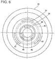
- the external air intake hole 66 is a hole that takes external air into the clutch chamber 64 formed as a sealed space. As shown in Figure 2 , the hole is provided in the front cover 60 that is disposed on the side face of the dry multi-plate clutch 7 so as to pass through in the axial direction in a radially inward location relative to the two clutch plates 71, 72. The specific radial location in which the external air intake hole 66 is provided aligns with the radial location on the dry multi-plate clutch 7 at which the air passage holes 74 that allow an air flow to move in the axial direction are provided. Thus, as shown in Figure 6 , three divided arcs formed in the front cover 60 constitute the external air intake holes 66.
- the external air discharge hole 67 is a hole that allows external discharge of air flow from inside the clutch chamber 64 formed as a sealed space. As shown in Figure 2 , the hole is provided in a radially outward location relative to the two clutch plates 71, 72 in the front cover 60 that is disposed on the side face of the dry multi-plate clutch 7 so as to pass through in the radial direction. The location where the external air discharge hole 67 is provided in the radial direction aligns with the radial location on the dry multi-plate clutch 7 at which the air passage gaps 77 that allow air flow to pass in the axial direction are provided. Thus, as shown in Figure 6 , three divided arcs that are formed in the front cover 60 producing holes that have a larger opening surface area than the external air intake holes 66 constitute the external air discharge holes 67.
- the separator inner wall 68 suppresses movement of air flow from inside the external air discharge hole 67 towards the interior of the external air intake hole 66 and is formed in the front cover 60 at a radial location on the inner face between the external air intake hole 66 and the external air discharge hole 67.
- the separator inner wall 68 in Embodiment 1, as shown in Figures 2 and 6 is a donut-shaped protrusion that is provided at a location on the inner face of the front cover 60 so that it surrounds the middle clutch hub shaft 2.
- the separator external wall 69 suppresses air flow from outside the external air discharge hole 67 to outside the external air intake hole 66 and is provided at a radial location on the external wall of the front cover 60 between the external air discharge hole 67 and the external air intake hole 66.
- the separator external wall 69 in Embodiment 1, as shown in Figures 2 and 6 is a donut-shaped protrusion that is provided at a location on the outside of the front cover 60 so that it surrounds the middle clutch hub shaft 2.
- the external air discharge hole 67 and the external air intake hole 66 of the front cover 60 are disposed so that the locations of the outside part of the external air discharge hole 67 and the discharge opening 67a are offset axially outwards from the locations of the outside parts of the external air intake hole 66 and the intake opening 66a. This is done in order to prevent the abrasion dust that is discharged from the external air discharge hole 67 from being suctioned back in from the external air intake hole 66.
- the clutch hydraulic pressure generated by the transmission unit T/M is supplied to the cylinder oil chamber 86 through a first clutch hydraulic path 85 formed in the cylinder housing 81.
- the hydraulic force resulting from multiplication of the hydraulic pressure by the received pressure surface area that acts on the piston 82 opposes the bias force produced by the return spring 84 that is interposed between the piston arm 83 and the clutch drum 6, causing the piston 82 to undergo a stroke in the rightwards direction in Figure 2 .
- the engaging force resulting from the difference between the hydraulic force and the biasing force is transferred from the piston 82, to the needle bearing 87, to the piston arm 83, to the arm press-plate 88, which pushes on the drive plate 71 and the driven plate 72, thereby engaging the dry multi-plate clutch 7.
- the centrifugal fan effect conveys air in the radial direction from the B region near the clutch hub 3 to the C region near the clutch drum 6, increasing the air pressure near the clutch drum 6 (positive pressure) and decreasing the air pressure near the clutch hub 3 (negative pressure).
- radial air flow E is generated whereby air moves in the radial direction from the clutch hub 3 to the clutch drum 6.
- the pressure radially inward in the dry multi-plate clutch 7 is decreased relative to atmospheric pressure (negative pressure), and the pressure radially outward in the dry multi-plate clutch 7 is increased relative to atmospheric pressure (positive pressure), producing a pressure relationship in which the air pressure at a radially outward location in the clutch is greater than atmospheric pressure, which is greater than the air pressure at a radially inward location in the clutch.
- the splined joining part of the drive plate 72 has low air passage resistance due to the gap allowance that is provided to ensure plate movement. Moreover, the air passage resistance is additionally decreased, because there are air passage gaps 77 that allow air flow to move in the axial direction at the splined joining parts of the driven plate 72 and the clutch drum 6. Thus, as a result of generation of the air flow E in the radial direction, an air pressure differential is produced between a radially outward location in the clutch which is at positive pressure and external air which is at atmospheric pressure.
- an air flow (F ⁇ E ⁇ G) is generated that is delineated by the following flow line: external air ⁇ external air intake hole 66 ⁇ axial gaps at radially inward locations in the clutch (e.g., air passage holes 74) ⁇ radial gaps of the clutch (e.g., facing grooves 76) ⁇ axial gaps at radially outward locations in the clutch (e.g., air passage gaps 77) ⁇ external air discharge hole 67 ⁇ external air.
- FIG 7 only radial air flow E is described on the side closest to the piston, but a plurality of radial air flows E arise for the respective facing grooves 76. For this reason, the abrasion dust that has separated from the surface of the friction facing 73 due to repeated clutch separations moves by being carried in the air flow (F ⁇ E ⁇ G) and is discharged externally.
- Embodiment 1 an example was presented in which a dry multi-plate clutch was used as the dry clutch.
- a single-plate dry clutch or the like may be used.
- the dry clutch may be a normal-closed dry clutch employing a diaphragm spring, or the like.
- Embodiment 1 an example was presented in which the drive plate 71 was joined by splines to the clutch hub 3, and the driven plate 72 was joined by splines to the clutch drum 6.
- the drive plate may be joined by splines to the clutch drum, and the driven plate may be joined by splines to the clutch hub.
- Embodiment 1 an example was presented in which the drive plate 71 had a friction facing 73.
- the driven plate may have the friction facing.
- Embodiment 1 an example was presented in which air passage holes 74 and/or air-passage gaps 77, and/or facing grooves 76, and the like, were provided in order to ensure an air flow path in the dry multi-plate clutch 7.
- the fitting gaps present in the splined joining parts may serve as axial air flow paths, and the gaps between the plates may serve as radial air flow paths. For this reason, it is not always necessary to provide air passage holes 74, and/or air passage gaps 77, and/or facing grooves 76, and the like.
- the inner wall structure may be a rib-shaped inner wall 68' in which the wall thickness of the front cover 60 is increased on the inner face between the external air discharge hole 67 and the external air intake hole 66, and the axial gaps between the two clutch plates 71, 72 are narrowed.
- the external wall structure may be a ring-shaped external wall, rather than a separator outer wall 69 produced as a donut-shaped protrusion.
- Embodiment 1 a preferred example of a hybrid drive power transmission system was presented in which the engine and motor/generator were mounted, and the dry multi-plate clutch was a drive mode transition clutch.
- this is also suitable for engine drive power transmission systems in which only an engine is mounted as a drive source, and a dry clutch is used as a start clutch, as with engine automobiles.
- the invention also is suitable for use in motor drive power transmission systems in which only a motor/generator is mounted as a drive source, and a dry clutch is used as a start clutch, as with electric vehicles, fuel cell vehicles, and the like.
Landscapes
- Engineering & Computer Science (AREA)
- General Engineering & Computer Science (AREA)
- Mechanical Engineering (AREA)
- Mechanical Operated Clutches (AREA)
- Hydraulic Clutches, Magnetic Clutches, Fluid Clutches, And Fluid Joints (AREA)
Description
- The present invention relates to a drive power transmission system that is suitable for automobile drive systems in which a dry clutch that disconnects the transmitting of drive power is installed in a sealed space.
- In the past, hybrid drive power transmission systems have been known in which the engine, the motor and clutch unit, and the accelerator unit are in a linked connection. With the motor and clutch unit, a dry multi-plate clutch is disposed inside the electric motor. Specifically, a clutch hub that is linked to the output shaft of the engine, a clutch drum to which a rotor of an electric motor is fixed, and which is linked to the input shaft of the transmission, and a dry multi-plate clutch that is interposed between the clutch hub and clutch drum are provided (e.g., refer to patent document 1). Further, a drive power transmission system according to the preamble portion of claim 1 is known from
patent document 2. Another drive power transmission system is known frompatent document 3. -
- Patent Document 1: Japanese Laid-Open Patent Application No.
2010-151313 - Patent Document 2:
US 1 635 353 A - Patent document 3:
CN 101 705 972 A - However, with conventional hybrid drive power transmission systems, a dry multi-plate clutch is housed in a dry space that is covered by a unit housing and sealed by a sealing member. For this reason, abrasion dust from the friction facing that is produced with repeated engagement and release of the clutch is not discharged and poor engagement and release of the dry multi-plate clutch arises as a result dragging due to the abrasion dust that has accumulated between the friction surfaces. The electric motor or clutch is thus disposed in the radial direction of the dry multi-plate clutch, and there is no space to provide abrasion dust discharge openings. There has thus been the problem that abrasion dust cannot be discharged radially.
- The present invention focuses on the above problem, it being an object of the invention to provide a drive power transmission system whereby abrasion dust that is generated between clutch plates that are pressed together via a friction facing can escape outwards by being carried in an axial air flow.
- In order to achieve the above objective, the present invention is a drive power transmission system in which a dry clutch that disconnects the transmitting of drive power is disposed in a sealed space.
- The dry clutch is means that has a first clutch plate, a second clutch plate, a friction facing, and a cover member.
- The first clutch plate is joined by splines with a clutch hub.
- The second clutch plate is joined by splines with a clutch drum.
- The friction facing is provided on one of the first and second clutch plates, and a friction surface presses against the other plate face during clutch engagement.
- The cover member has an external air intake hole through which external air is taken into the sealed space and an external air discharge hole through which air flow is discharged from inside the sealed space to external air.
- The external air intake hole is provided so that the cover member disposed on a side face of the dry clutch is axially passed through radially inwardly from the two clutch plates.
- The external air discharge hole is provided so that the cover member disposed on a side face of the dry clutch is axially passed through radially outwardly from the two clutch plates.
- As described above, the cover member that is disposed on a side face of the dry clutch has an external air intake hole through which external air is taken into the sealed space and an external air discharge hole through which an air flow from the sealed space is discharged into external air. A configuration is adopted in which the external air intake hole is provided radially inwardly from the two clutch plates, and the external air discharge hole is provided radially outwardly from the two clutch plates.
- For this reason, as a result of the effect of centrifugal pressure from rotation about the clutch rotational axis, the radially inward pressure of the dry clutch is lower than atmosphere pressure (negative pressure), and the radially outward pressure of the dry clutch is higher than atmospheric pressure (positive pressure), thereby producing a pressure relationship in which the radially-outward clutch air pressure is greater than atmospheric pressure, which is greater than the radially-inward clutch air pressure.
- Consequently, the external air which is at atmospheric pressure is drawn in under negative pressure, moves from the external air intake hole radially inward in the clutch, and then moves under centrifugal pressure from the a radially inward location in the clutch towards a radially outward location. The air is then discharged under positive pressure from the circumference of the clutch towards the external air discharge hole before being discharged into the external air from the external air discharge hole. As a result of this external air transfer action, an air flow is generated that is delineated by a flow line running as follows: external air → external air intake hole → axial gaps radially inward in the clutch → radial gaps of the clutch → axial gaps radially outward in the clutch → external air discharge hole → external air. For this reason, abrasion dust that has been released from the surface of the friction facing is transferred by being carried along by a series of air flows resulting from the axial intake air flow, the radial air flow and the axial discharge air flow, thereby being externally discharged.
- As a result, the abrasion dust that arises between the clutch plates that are pressed together via friction facing can be externally discharged by being carried by a radial air flow.
-
- [
Figure 1 ] General schematic diagram showing the hybrid drive power transmission system of Embodiment 1 (example of the drive power transmission system). - [
Figure 2 ] Specific sectional view showing the configuration of the motor and the clutch unit in the hybrid drive power transmission system of Embodiment 1. - [
Figure 3 ] Exploded oblique view showing the piston assembly of the dry multi-plate clutch in the hybrid drive power transmission system of Embodiment 1. - [
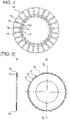
Figure 4 ] Plan view showing the drive plate of the dry multi-plate clutch device in the hybrid drive power transmission system of Embodiment 1. - [
Figure 5 ] A-A sectional view (a) and plan view (b) showing the drive plate of the dry multi-plate clutch in the hybrid drive power transmission system of Embodiment 1. - [
Figure 6 ] Side view showing the front cover of the dry multi-plate clutch in the hybrid drive power transmission system of Embodiment 1. - [
Figure 7 ] Illustrative diagram of the operation of the abrasion dust discharge in the hybrid drive power transmission system of Embodiment 1. - [
Figure 8 ] Specific sectional view showing the configuration of the motor and clutch unit in the hybrid drive power transmission system having a rib-shaped inner wall structure. - A preferred embodiment of the drive power transmission system of the present invention is described below based on Embodiment 1 shown in the drawings.
- First, the configuration will be described.
- The configuration of the hybrid drive power transmission system of Embodiment 1 is described below under the headings: General configuration, Motor and clutch unit configuration, Dry multi-plate clutch configuration, and Air flow effect abrasion dust discharge configuration.
-
Figure 1 is a general schematic diagram showing the hybrid drive power transmission system of Embodiment 1 (example of drive power transmission system). The general configuration of the device is described below with reference toFigure 1 . - The hybrid drive power transmission system of Embodiment 1, as shown in
Figure 1 , comprises an engine Eng, a motor and clutch unit M/C, an transmission unit T/M, an engine output shaft 1, aclutch hub shaft 2, aclutch hub 3, aclutch drum shaft 4, atransmission input shaft 5, aclutch drum 6, a dry multi-plate clutch 7 (dry clutch), aslave cylinder 8, and a motor/generator 9. - The
slave cylinder 8 that controls oil pressure that engages and releases the dry multi-plate clutch 7 is generally referred to as a "concentric slave cylinder" (CSC). - With the hybrid drive power transmission system of Embodiment 1, when the dry multi-plate clutch 7 that is normally open is released, the motor/
generator 9 andtransmission input shaft 5 are linked by theclutch drum 6 and theclutch drum shaft 4, producing an "electric driving mode." Next, the dry multi-plate clutch 7 is made to engage under hydraulic pressure from theslave cylinder 8, the engine Eng and motor/generator 9, and the engine output shaft 1 andclutch hub shaft 2 are linked via adamper 21. Next, linkage occurs via the dry multi-plate clutch 7 in which theclutch hub 3 andclutch drum 6 are engaged, producing a "hybrid driving mode." - The motor and clutch unit M/C has a dry multi-plate clutch 7, a
slave cylinder 8, and a motor/generator 9. The dry multi-plate clutch 7 is linked and connected to the engine Eng and disconnects the transmitting of drive power from the engine Eng. Theslave cylinder 8 controls the oil pressure for engaging and releasing the dry multi-plate clutch 7. The motor/generator 9 is disposed at an outer circumferential location on theclutch drum 6 of the dry multi-plate clutch 7 and transfers power to thetransmission input shaft 5. - A
cylinder housing 81 that has a first clutchhydraulic path 85 is provided on theslave cylinder 8, with a seal maintained by an O-ring 10. - The motor/
generator 9 has arotor support frame 91 that is integrated with theclutch drum 6 and arotor 92 enclosing a permanent magnet that is fixed and supported on therotor support frame 91. Next, there is astator 94 that is fixed on thecylinder housing 81 and is disposed at therotor 92 with anair gap 93 interposed, and astator coil 95 that is wound around thestator 94. Awater jacket 96 that allows flow of cooling water is formed in thecylinder housing 81. - The transmission unit T/M is linked and connected to the motor and clutch unit M/C and has a
transmission housing 41, a V-beltstepless transmission mechanism 42, and an oil pump O/P. The V-beltstepless transmission mechanism 42 is housed in thetransmission housing 41, with the V-belt suspended between two pulleys, providing a stepless variable gear ratio by varying the belt contact diameter. The oil pump O/P is a hydraulic oil source that provides hydraulic pressure to the required components. With the oil pump pressure as the source pressure, hydraulic pressure is conducted to the required components from a control valve not shown in the drawings that modulates the pressure, e.g., the transmission hydraulic pressure, that is provided to the pulley chamber or the clutch/brake hydraulic pressure. This transmission unit T/M also has a forward/reverse switching mechanism 43, anoil tank 44, and anend plate 45. Theend plate 45 has a second clutch hydraulic path 47 (Figure 2 ). - The oil pump O/P is driven as a result of transfer of rotational drive torque from the
transmission input shaft 5 via a chain drive mechanism. The chain drive mechanism has a drive-side sprocket 51 that rotates along with rotational drive of thetransmission input shaft 5, a driven-side sprocket 52 that rotationally drives apump shaft 57, and achain 53 that is suspended on bothsprockets side sprocket 51 is mounted between thetransmission input shaft 5 and anend plate 45 and is rotatably supported via abrush 55 on astator shaft 54 that is fixed to thetransmission housing 41. Thus, splined joining occurs with thetransmission input shaft 5, and rotational drive torque from thetransmission input shaft 5 is transmitted via afirst adaptor 56 that fits via teeth on the drive-side sprocket 51. -
Figure 2 is a specific sectional view showing the configuration of the motor and clutch unit in the hybrid drive power transmission system of Embodiment 1.Figure 3 is an exploded oblique view of the piston assembly of the dry multi-plate clutch in the hybrid drive power transmission system of Embodiment 1. The configuration of the motor and clutch unit M/C is described below with reference toFigures 2 and3 . - The
clutch hub 3 is linked to the engine output shaft 1 of the engine Eng. As shown inFigure 2 , in theclutch hub 3, a drive plate 71 (first clutch plate) of the dry multi-plate clutch 7 is held by splined joining. - The
clutch drum 6 is linked to thetransmission input shaft 5 of the transmission unit T/M. As shown inFigure 2 , a driven plate 72 (second clutch plate) of the dry multi-plate clutch 7 is held by splined joining on thisclutch drum 6. - With the dry multi-plate clutch 7, the
drive plate 71 and the drivenplate 72 to which friction facings 73, 73 are adhered on both surfaces are interposed alternately between theclutch hub 3 and theclutch drum 6 so that they are aligned in multiple plates. In other words, by engagement of the dry multi-plate clutch 7, torque transfer between theclutch hub 3 and theclutch drum 6 is enabled, and by release of the dry multi-plate clutch 7, torque transfer between theclutch hub 3 and theclutch drum 6 is disconnected. - The
slave cylinder 8 is a hydraulic pressure actuator that controls engagement and release of the dry multi-plate clutch 7 and is disposed at a location that is between the transmission unit T/M and theclutch drum 6. As shown inFigure 2 , theslave cylinder 8 has apiston 82 that is slidably provided in acylinder hole 80 of thecylinder housing 81, a first clutchhydraulic path 85 that is formed in thecylinder housing 81 and conducts clutch pressure output by the transmission unit T/M, and acylinder oil housing 86 that communicates with the first clutchhydraulic path 85. As shown inFigure 2 , aneedle bearing 87, apiston arm 83, areturn spring 84, and an arm press-plate 88 are interposed between thepiston 82 and the dry multi-plate clutch 7. - The
piston arm 83 generates press force for the dry multi-plate clutch 7 as a result of the press force from theslave cylinder 8, and the piston arm is slidably provided in a through-hole 61 formed in theclutch drum 6. Thereturn spring 84 is interposed between thepiston arm 83 and theclutch drum 6. Theneedle bearing 87 is interposed between thepiston 82 and thepiston arm 83, and thepiston 82 suppresses inducement of rotation that occurs along with rotation of thepiston arm 83. The arm press-plate 88 is provided integrally with elastic bellows-shapedsupport members support members clutch drum 6. Influx of oil leaking from thepiston arm 83 into the dry multi-plate clutch 7 is blocked by the arm press-plate 88 and the elastic cornice-shapedsupport members support member 89 and the arm press-plate 88 that is sealed and fixed at the piston arm attachment location of theclutch drum 6 have a partitioning function that produces a wet space in which theslave cylinder 8 is disposed and a dry space in which the dry multi-plate clutch 7 is disposed. - As shown in
Figure 3 , thepiston arm 83 comprises anarm body 83a that is formed in the shape of a ring andarm protrusion ridges 83b that protrude from thearm body 83a in four locations. - As shown in
Figure 3 , thereturn spring 84 comprises aspring support plate 84a that is formed in the shape of a ring, andmultiple coil springs 84b that are fixed on thespring support plate 84a. - As shown in
Figure 2 , the arm press-plate 88 is pressed and fixed on thearm protrusion ridges 83b of thepiston arm 83. As shown inFigure 3 , the bellows-shapedelastic support members plate 88. - The leak oil recovery path in Embodiment 1, as shown in
Figure 2 , comprises afirst bearing 12, afirst seal member 31, aleak oil path 32, a firstrecovery oil path 33, and a secondrecovery oil path 34. Specifically, the path is a circuit whereby leak oil from the sliding part of thepiston 82 passes through the firstrecovery oil path 33 and the secondrecovery oil path 34 that are sealed by afirst seal member 31 and then returns to the transmission unit T/M. In addition, the path is a circuit whereby leak oil from the sliding part of thepiston arm 83 passes through theleak oil path 32 that is sealed by the partitioning elastic members (arm press-plate 88, bellows-shapedelastic support member 89, 89) and the firstrecovery oil path 33 and secondrecovery oil path 34 that are sealed by thefirst seal member 31 and then returns to the transmission unit T/M. - The bearing lubricating oil path of Embodiment 1, as shown in
Figure 2 , comprises aneedle bearing 20, asecond seal member 14, a first shaftcore oil path 19, a second shaftcore oil path 18, a lubricating oil path 16, and agap 17. This bearing lubricating oil path effects bearing lubrication through a route whereby the bearing lubricating oil from the transmission unit T/M passes through theneedle bearing 20, thefirst bearing 12 that rotatably support theclutch drum 6 on thecylinder housing 81, and theneedle bearing 87 that is interposed between thepiston 82 and thepiston arm 83, and then returns to the transmission unit T/M. - The
second sealing member 14, as shown inFigure 2 , is interposed between theclutch hub 3 and theclutch drum 6. This second sealingmember 14 seals inflow of bearing lubrication oil from the wet space in which theslave cylinder 8 is disposed to the dry space in which the dry multi-plate clutch 7 is disposed. -
Figures 4 to 6 are diagrams showing the configurational elements of the dry multi-plate clutch 7. The configuration of the dry multi-plate clutch 7 is described with reference toFigure 2 andFigures 4 to 6 . - The dry multi-plate clutch 7 is a clutch that connects and disconnects drive power from the engine Eng and is disposed, as shown in
Figure 2 , in aclutch chamber 64 formed as a sealed space enclosed by theclutch hub shaft 2, theclutch hub 3, theclutch cover 6, and afront cover 60. Thus, the configurational elements of the dry multi-plate clutch 7 comprise the drive plate 71 (first clutch plate), the driven plate 72 (second clutch plate), the friction facing 73, and the front cover 60 (cover member). - The
drive plate 71 is joined by splines to theclutch hub 3 and has air passage holes 74 whereby an air flow passes through in the axial direction at the splined joining parts with theclutch hub 3. In the spline teeth that mesh with the spline parts of theclutch hub 3, as shown inFigure 4 , thedrive plate 71 has air passage holes 74 at locations onspline tooth protrusions 75 that protrude radially inward at locations that are inwards from the facinggrooves 76 that are formed in the friction facing 73. Thus, thedrive plate 71, as shown inFigure 2 , is provided so that the air passage holes 74 of the multiple plates (four plates in Embodiment 1) are in communication in the axial direction. - The driven
plate 72 is joined by splines to theclutch drum 6 and hasair passage gaps 77 that allow an air flow to flow in the axial direction in the splined joining parts with theclutch drum 6. As shown inFigure 6 ,depressions 78 are formed in the center locations of the spline teeth protrusions that protrude radially outward, and theair passage gaps 77 are provided as gap spaces that are open when joining with the spline teeth of theclutch drum 6 has been brought about. - The friction facing 73 is provided on both faces of the
drive plate 71, and the friction surfaces are pressed against the plate faces of the drivenplates 72 when the clutch is engaged. The friction facing 73, as shown inFigure 5 , is a ring-shaped plate member having facinggrooves 76 that are formed as straight radial lines extending radially from an inner location to an outer location. The facinggrooves 76 have a depth whereby the groove shape is retained even when abrasion of the facing has progressed to some degree. - The
front cover 60 is integrally fixed on thecylinder housing 81 of the static member that is supported by thefirst bearing 12 on theclutch drive shaft 4 and covers the motor/generator 9 and the dry multi-plate clutch 7. In other words, thefront cover 60 is a static member that is sealed by acover seal 15 while being supported by asecond bearing 13 on theclutch hub shaft 2. In the internal space that is formed as a result of being covered by thefront cover 60 and thecylinder housing 81, the space that is towards the clutch rotational shaft CL (= rotor shaft) is used for theclutch chamber 64 that houses the dry multi-plate clutch 7, and the outer space of theclutch chamber 64 is used for amotor chamber 65 that houses the motor/generator 9. Thus, theclutch chamber 64 and themotor chamber 65 that are separated by adust sealing member 62 are dry spaces that block ingress of oil. - The dry multi-plate clutch 7 abrasion dust discharge configuration resulting from air flow effects is described below with reference to
Figure 2 andFigures 4 to 6 . - The abrasion dust discharge configuration in the dry multi-plate clutch 7 that is produced as a result of air flow effects comprises the air passage holes 74, the
air passage gaps 77, and the facinggrooves 76. - The air passage holes 74 are formed in the
drive plates 71, theclutch hub 3, and the splined joining parts, allowing an air flow to pass in the axial direction (Figure 4 ) - The
air passage gaps 77 are formed in the drivenplates 72, theclutch drum 6, and the splined joining parts, allowing an air flow to pass in the axial direction (Figure 5 ). - The facing
grooves 76 are formed as straight radial lines extending radially from an inner location to an outer location in the friction facing 73, allowing air flow to pass in the radial direction (Figure 4 ). - As shown in
Figure 2 andFigure 6 , the abrasion dust discharge configuration of thefront cover 60 produced as a result of air flow effects comprises an externalair intake hole 66, an externalair discharge hole 67, a separator inner wall 68 (inner wall structure), and a separator outer wall 69 (outer wall structure). - The external
air intake hole 66 is a hole that takes external air into theclutch chamber 64 formed as a sealed space. As shown inFigure 2 , the hole is provided in thefront cover 60 that is disposed on the side face of the dry multi-plate clutch 7 so as to pass through in the axial direction in a radially inward location relative to the twoclutch plates air intake hole 66 is provided aligns with the radial location on the dry multi-plate clutch 7 at which the air passage holes 74 that allow an air flow to move in the axial direction are provided. Thus, as shown inFigure 6 , three divided arcs formed in thefront cover 60 constitute the external air intake holes 66. - The external
air discharge hole 67 is a hole that allows external discharge of air flow from inside theclutch chamber 64 formed as a sealed space. As shown inFigure 2 , the hole is provided in a radially outward location relative to the twoclutch plates front cover 60 that is disposed on the side face of the dry multi-plate clutch 7 so as to pass through in the radial direction. The location where the externalair discharge hole 67 is provided in the radial direction aligns with the radial location on the dry multi-plate clutch 7 at which theair passage gaps 77 that allow air flow to pass in the axial direction are provided. Thus, as shown inFigure 6 , three divided arcs that are formed in thefront cover 60 producing holes that have a larger opening surface area than the external air intake holes 66 constitute the external air discharge holes 67. - The separator
inner wall 68 suppresses movement of air flow from inside the externalair discharge hole 67 towards the interior of the externalair intake hole 66 and is formed in thefront cover 60 at a radial location on the inner face between the externalair intake hole 66 and the externalair discharge hole 67. The separatorinner wall 68 in Embodiment 1, as shown inFigures 2 and6 , is a donut-shaped protrusion that is provided at a location on the inner face of thefront cover 60 so that it surrounds the middleclutch hub shaft 2. - The separator
external wall 69 suppresses air flow from outside the externalair discharge hole 67 to outside the externalair intake hole 66 and is provided at a radial location on the external wall of thefront cover 60 between the externalair discharge hole 67 and the externalair intake hole 66. The separatorexternal wall 69 in Embodiment 1, as shown inFigures 2 and6 , is a donut-shaped protrusion that is provided at a location on the outside of thefront cover 60 so that it surrounds the middleclutch hub shaft 2. - The external
air discharge hole 67 and the externalair intake hole 66 of thefront cover 60, as shown inFigure 2 , are disposed so that the locations of the outside part of the externalair discharge hole 67 and thedischarge opening 67a are offset axially outwards from the locations of the outside parts of the externalair intake hole 66 and theintake opening 66a. This is done in order to prevent the abrasion dust that is discharged from the externalair discharge hole 67 from being suctioned back in from the externalair intake hole 66. - The operation of the device is described below.
- Operation of the hybrid drive power transmission system of Embodiment 1 is described below under the headings: "Slave cylinder clutch engagement/release operation" and "Abrasion dust discharge action resulting from air flow effects."
- The clutch engagement/release operation whereby the dry multi-plate clutch 7 is engaged and released by the
slave cylinder 8 is described below with reference toFigure 2 . - When the dry multi-plate clutch 7 is engaged by the
slave cylinder 8, the clutch hydraulic pressure generated by the transmission unit T/M is supplied to thecylinder oil chamber 86 through a first clutchhydraulic path 85 formed in thecylinder housing 81. The hydraulic force resulting from multiplication of the hydraulic pressure by the received pressure surface area that acts on thepiston 82 opposes the bias force produced by thereturn spring 84 that is interposed between thepiston arm 83 and theclutch drum 6, causing thepiston 82 to undergo a stroke in the rightwards direction inFigure 2 . Thus, the engaging force resulting from the difference between the hydraulic force and the biasing force is transferred from thepiston 82, to theneedle bearing 87, to thepiston arm 83, to the arm press-plate 88, which pushes on thedrive plate 71 and the drivenplate 72, thereby engaging the dry multi-plate clutch 7. - When the dry multi-plate clutch 7 that is in an engaged state is released, the hydraulic oil that is supplied to the
cylinder oil chamber 86 passes through the clutchhydraulic path 85 and is extracted to the transmission unit T/M, causing a decrease in the hydraulic pressure acting on thepiston 82. The urging force due to thereturn spring 84 thus supersedes the hydraulic force, and the arm press-plate 88 and thepiston arm 83 that are integrally configured undergo a stoke in the leftward direction inFigure 2 . As a result, the engaging force that has been transferred to the arm press-plate 88 is released, and the dry multi-plate clutch 7 is released. - As described above, when engagement and release of the dry multi-plate clutch 7 is repeated, the surface of the friction facing material separates and falls away, producing abrasion dust that accumulates between the two
clutch plates Figure 7 . - When at least one of the
clutch hub 3 and theclutch drum 6 rotates about the clutch rotational shaft CL, because the facinggrooves 76 are present on the friction facing 73, a centrifugal fan effect is produced in which theclutch hub 3 having the friction facing 73 on both faces acts as a blade. - As shown in
Figure 7 , the centrifugal fan effect conveys air in the radial direction from the B region near theclutch hub 3 to the C region near theclutch drum 6, increasing the air pressure near the clutch drum 6 (positive pressure) and decreasing the air pressure near the clutch hub 3 (negative pressure). As a result of this air pressure differential, radial air flow E is generated whereby air moves in the radial direction from theclutch hub 3 to theclutch drum 6. Specifically, the pressure radially inward in the dry multi-plate clutch 7 is decreased relative to atmospheric pressure (negative pressure), and the pressure radially outward in the dry multi-plate clutch 7 is increased relative to atmospheric pressure (positive pressure), producing a pressure relationship in which the air pressure at a radially outward location in the clutch is greater than atmospheric pressure, which is greater than the air pressure at a radially inward location in the clutch. - As a result of the generation of this radial air flow, an air pressure differential is produced between external air that is at atmospheric pressure and air that is radially inwards in the clutch, which is at negative pressure. Consequently, as shown in
Figure 7 , an axial air flow F that is radially inward is produced whereby external air that is taken in from the external air intake holes 66 passes through the air passage holes 74 towards theclutch hub 3 where the air pressure is decreased. - In addition, the splined joining part of the
drive plate 72 has low air passage resistance due to the gap allowance that is provided to ensure plate movement. Moreover, the air passage resistance is additionally decreased, because there areair passage gaps 77 that allow air flow to move in the axial direction at the splined joining parts of the drivenplate 72 and theclutch drum 6. Thus, as a result of generation of the air flow E in the radial direction, an air pressure differential is produced between a radially outward location in the clutch which is at positive pressure and external air which is at atmospheric pressure. Consequently, as shown inFigure 7 , the direction changes from the axial direction at a radially inward location to the radial direction, and the air flow that has entered near theclutch drum 6 passes from theair passage gaps 77 in the splined joining parts through the externalair discharge hole 67, producing an axial air flow G at a radially outward location, which is then discharged to external air. - As a result of this air flow generation action, as indicated by the arrows in
Figure 7 , an air flow (F → E → G) is generated that is delineated by the following flow line: external air → externalair intake hole 66 → axial gaps at radially inward locations in the clutch (e.g., air passage holes 74) → radial gaps of the clutch (e.g., facing grooves 76) → axial gaps at radially outward locations in the clutch (e.g., air passage gaps 77) → externalair discharge hole 67 → external air. InFigure 7 , only radial air flow E is described on the side closest to the piston, but a plurality of radial air flows E arise for therespective facing grooves 76. For this reason, the abrasion dust that has separated from the surface of the friction facing 73 due to repeated clutch separations moves by being carried in the air flow (F → E → G) and is discharged externally. - The effect of the invention is described below.
- With the hybrid drive power transmission system of Embodiment 1, the effects listed below can be obtained.
-
- (1) With a drive power transmission system in which a dry clutch (multi-plate clutch 7) that disconnects drive power transfer is disposed inside a sealed space (clutch chamber 64),
the dry clutch (dry multi-plate clutch 7) comprises:- a first clutch plate (drive plate 71) that is joined by splines to a
clutch hub 3; - a second clutch plate (driven plate 72) that is joined by splines to a
clutch drum 6; - a friction facing 73 that is provided on either the first clutch plate (drive plate 71) or second clutch plate (driven plate 72), with the friction surface pressing against the other plate face during clutch engagement; and
- a cover member (front cover 60) having an external
air intake hole 66 that takes external air into the sealed space (clutch chamber 64) and an externalair discharge hole 67 that discharges the air flow from inside the sealed space (clutch chamber 64) to external air; - the external
air intake hole 66 being provided on the cover member (front cover 60) that is disposed on a side face of the dry clutch (dry multi-plate clutch 7) so as to pass through in the axial direction at a radially inward location relative to the twoclutch plates air discharge hole 67 being provided on the cover member (front cover 60) that is disposed on a side face of the dry clutch (dry multi-plate clutch 7) so as to pass through in the axial direction at a radially outward location relative to the twoclutch plates 71, 72 (FIGs. 2 ,7 ).
For this reason, abrasion dust that is generated between the clutch plates (driveplate 71, driven plate 72) that are pressed together with the friction facing 73 interposed is carried in an axial air flow and is discharged outwards. - a first clutch plate (drive plate 71) that is joined by splines to a
- (2) Air passage holes 74 that allow air flow to pass in the axial direction are provided in the first clutch plate (drive plate 71) at the splined joining parts with the
clutch hub 3, and the radial location at which the externalair intake hole 66 is provided is aligned with the radial location on the dry clutch (dry multi-plate clutch 7) at which the air passage holes 74 are provided (Figure 7 ).
For this reason, in addition to the effects described in (1) above, the air passage resistance and flow-line bending resistance of the axial air flow F at a radially inward location are suppressed, producing a smoother external air intake, while also increasing the flow rate of the axial air flow F at a radially inward location that exhibits the air flow effect of discharging abrasion dust. - (3)
Air flow gaps 77 that allow passage of air flow in the axial direction are provided in the second clutch plate (driven plate 72) at the splined joined parts with theclutch drum 6, and the radial location at which the externalair discharge hole 67 is provided aligns with the radial position on the dry clutch (dry multi-plate clutch 7) where theair passage gaps 77 are provided (Figure 7 ).
For this reason, in addition to the effects in (1) and (2) above, the air passage resistance and flow-line bending resistance of the axial air flow G at a radially outward location are suppressed, producing a smoother external air intake, while also increasing the flow rate of the axial air flow G at a radially outward location that exhibits the air flow effect of discharging abrasion dust. - (4) In the cover member (front cover 60), the locations of the
discharge opening 67a and the outer part of the externalair discharge hole 67 are offset outwards in the axial direction from the locations of theintake opening 66a and the outer part of the external air intake hole 66 (Figure 2 ).
For this reason, in addition to the effects of (1) to (3), abrasion dust that has been discharged from the externalair discharge hole 67 can be prevented from being suctioned back in from the externalair intake hole 66. - (5) A separator inner wall 68 (inner wall structure) that suppresses movement of air flow from the inside of the external
air discharge hole 67 to the inside of the externalair intake hole 66 is provided on the cover member (front cover 60) at an inner face location in the radial direction between the externalair discharge hole 67 and the externalair intake hole 66.
For this reason, in addition to the effects of (1) to (4) above, movement of air flow from the inside of the externalair discharge hole 67 to the inside of the externalair intake hole 66 is suppressed, and abrasion dust that is carried in the air flow in the sealed space (clutch housing 64) towards the externalair discharge hole 67 is prevented from returning to the externalair intake hole 66. As a result, abrasion dust discharge effects from the externalair discharge hole 67 are improved. - (6) a separator outer wall 69 (outer wall structure) that suppresses movement of air flow from the outside of the external
air discharge hole 67 towards the outside of the externalair intake hole 66 is provided on the cover member (front cover 60) at a location on the radially outer face between the externalair discharge hole 67 and the externalair intake hole 66.
For this reason, in addition to the effects of (1) to (5), movement of air flow from the outside of the externalair discharge hole 67 to the outside of the externalair intake hole 66 is suppressed, and abrasion dust that has been discharged from the externalair discharge hole 67 is prevented from returning again to the externalair intake hole 66. - The drive power transmission system of the present invention was described above with reference to Embodiment 1. However, the specific configuration is not restricted to that of Embodiment 1, and various design modifications and additions are permissible while remaining within the spirit of the invention as described in the claims.
- In Embodiment 1, an example was presented in which a dry multi-plate clutch was used as the dry clutch. However, in another example, a single-plate dry clutch or the like may be used.
- In Embodiment 1, an example of a normal-open dry clutch was presented. However, in another example, the dry clutch may be a normal-closed dry clutch employing a diaphragm spring, or the like.
- In Embodiment 1, an example was presented in which the
drive plate 71 was joined by splines to theclutch hub 3, and the drivenplate 72 was joined by splines to theclutch drum 6. However, in another example, the drive plate may be joined by splines to the clutch drum, and the driven plate may be joined by splines to the clutch hub. - In Embodiment 1, an example was presented in which the
drive plate 71 had a friction facing 73. However, in another example, the driven plate may have the friction facing. - In Embodiment 1, an example was presented in which air passage holes 74 and/or air-
passage gaps 77, and/or facinggrooves 76, and the like, were provided in order to ensure an air flow path in the dry multi-plate clutch 7. However, even if there are no air passage holes 74 and/orair passage gaps 77, the fitting gaps present in the splined joining parts may serve as axial air flow paths, and the gaps between the plates may serve as radial air flow paths. For this reason, it is not always necessary to provide air passage holes 74, and/orair passage gaps 77, and/or facinggrooves 76, and the like. - In Embodiment 1, an example was presented in which a separator
inner wall 68 produced by a donut-shaped protrusion was used as an inner wall structure. However, for example, as shown inFigure 8 , the inner wall structure may be a rib-shaped inner wall 68' in which the wall thickness of thefront cover 60 is increased on the inner face between the externalair discharge hole 67 and the externalair intake hole 66, and the axial gaps between the twoclutch plates outer wall 69 produced as a donut-shaped protrusion. When the inner wall structure or outer wall structure is a rib-shaped member, the rigidity of thefront cover 60 having the externalair intake hole 66 and the externalair discharge hole 67 can be increased. - In Embodiment 1, a preferred example of a hybrid drive power transmission system was presented in which the engine and motor/generator were mounted, and the dry multi-plate clutch was a drive mode transition clutch. However, this is also suitable for engine drive power transmission systems in which only an engine is mounted as a drive source, and a dry clutch is used as a start clutch, as with engine automobiles. In addition, the invention also is suitable for use in motor drive power transmission systems in which only a motor/generator is mounted as a drive source, and a dry clutch is used as a start clutch, as with electric vehicles, fuel cell vehicles, and the like.
- This application claims priority based on Patent Application
2011-224625
Claims (5)
- A drive power transmission system in which a dry clutch that disconnects the transmitting of drive power is disposed inside a sealed space, the dry clutch (7) comprising:a first clutch plate (71) that is joined by splines to a clutch hub (3);a second clutch plate (72) that is joined by splines to a clutch drum (6); anda friction facing (73) that is provided on the first clutch plate (71) or second clutch plate (72), a friction surface pressing against the other plate face during clutch engagement;characterized bya cover member (60) having an external air intake hole (66) through which external air is taken into the sealed space (64) and an external air discharge hole (67) through which the air flow is discharged from inside the sealed space (64) to the external air;the external air intake hole (66) is provided on the cover member (60) disposed on a side face of the dry clutch (7) so as to pass axially through radially inwardly from the two clutch plates (71, 72), and the external air discharge hole (67) is provided on the cover member disposed on a side face of the dry clutch (7) so as to pass axially through radially outwardly from the two clutch plates (71, 72), whereinthe second clutch plate (72) is provided with an air flow gap (77) through which air flow can pass in the axial direction at the location of spline-joining with the clutch drum (6), andthe radial location at which the external air discharge hole (67) is provided is aligned with the radial position on the dry clutch (7) in which the air passage gap (77) is provided.
- The drive power transmission system according to claim 1, characterized in that the first clutch plate (71) is provided with an air passage hole (74) through which air can flow in the axial direction at the location of spline-joining with the clutch hub (3), and
the radial location at which the external air intake hole (66) is provided is aligned with the radial location on the dry clutch (7) in which the air passage hole (74) is provided. - The drive power transmission system according to any of claims 1 or 2, characterized in that the cover member (60) is disposed so that the locations of the discharge opening (67a) and the outer part of the external air discharge hole (67) are offset outwards in the axial direction from the locations of the intake opening (66a) and the outer part of the external air intake hole (66).
- The drive power transmission system according to any of claims 1 to 43, characterized in that the cover member (60) is provided with an inner wall structure (68) at a radially inner face location between the external air discharge hole (67) and the external air intake hole (66) for suppressing the flow of air from the inside of the external air discharge hole (67) to the inside of the external air intake hole (66).
- The drive power transmission system according to any of claims 1 to 4, characterized in that the cover member (60) is provided with an outer wall structure (69) at a location on the radially outer face between the external air discharge hole (67) and the external air intake hole for suppressing the flow of air from the outside of the external air discharge hole towards the outside of the external air intake hole.
Applications Claiming Priority (2)
| Application Number | Priority Date | Filing Date | Title |
|---|---|---|---|
| JP2011224625 | 2011-10-12 | ||
| PCT/JP2012/076276 WO2013054827A1 (en) | 2011-10-12 | 2012-10-11 | Drive power transmission system |
Publications (4)
| Publication Number | Publication Date |
|---|---|
| EP2767724A1 EP2767724A1 (en) | 2014-08-20 |
| EP2767724A4 EP2767724A4 (en) | 2016-08-03 |
| EP2767724B1 EP2767724B1 (en) | 2019-05-08 |
| EP2767724B2 true EP2767724B2 (en) | 2022-06-29 |
Family
ID=48081880
Family Applications (1)
| Application Number | Title | Priority Date | Filing Date |
|---|---|---|---|
| EP12840119.7A Active EP2767724B2 (en) | 2011-10-12 | 2012-10-11 | Drive power transmission system |
Country Status (5)
| Country | Link |
|---|---|
| US (1) | US9347501B2 (en) |
| EP (1) | EP2767724B2 (en) |
| JP (1) | JP5776781B2 (en) |
| CN (1) | CN103857937B (en) |
| WO (1) | WO2013054827A1 (en) |
Families Citing this family (11)
| Publication number | Priority date | Publication date | Assignee | Title |
|---|---|---|---|---|
| JP5499998B2 (en) * | 2010-08-31 | 2014-05-21 | 日産自動車株式会社 | Driving force transmission device |
| DE112014002014B4 (en) * | 2013-04-19 | 2018-10-04 | Schaeffler Technologies AG & Co. KG | Hybrid module for motor vehicle |
| DE102014204841A1 (en) * | 2014-03-14 | 2015-09-17 | Magna Powertrain Ag & Co. Kg | clutch module |
| DE202014009106U1 (en) * | 2014-10-20 | 2016-01-25 | Liebherr-Components Biberach Gmbh | hydraulic unit |
| US20170167545A1 (en) * | 2015-12-11 | 2017-06-15 | Ford Global Technologies, Llc | Clutch system for a vehicle powertrain |
| DE102017108655B3 (en) * | 2017-04-24 | 2018-04-12 | Schaeffler Technologies AG & Co. KG | Hybrid module with ventilated multi-disc clutch |
| US10794433B2 (en) * | 2017-09-20 | 2020-10-06 | Schaeffler Technologies AG & Co. KG | Piston for clutch assembly |
| CN108644244A (en) * | 2018-07-16 | 2018-10-12 | 重庆卓格豪斯机械有限公司 | Mini-tiller clutch |
| JP7176391B2 (en) * | 2018-12-11 | 2022-11-22 | 株式会社ジェイテクト | clutch device |
| WO2021075443A1 (en) * | 2019-10-17 | 2021-04-22 | 株式会社ヴァレオジャパン | Electromagnetic clutch |
| US11162542B2 (en) * | 2020-03-09 | 2021-11-02 | Schaeffler Technologies AG & Co. KG | Clutch piston that applies through compensation dam |
Citations (6)
| Publication number | Priority date | Publication date | Assignee | Title |
|---|---|---|---|---|
| US1731416A (en) † | 1927-03-23 | 1929-10-15 | Int Motor Co | Air-cooled clutch |
| US2290542A (en) † | 1940-03-07 | 1942-07-21 | Ajax Mfg Co | Clutch |
| US2675106A (en) † | 1950-06-30 | 1954-04-13 | Massey Ltd B & S | Air cooled fluid clutch |
| US3945476A (en) † | 1973-04-30 | 1976-03-23 | Quick-Rotan Becker & Notz Kg | Motor construction |
| US4382497A (en) † | 1980-03-13 | 1983-05-10 | Toyota Jidosha Kogyo Kabushiki Kaisha | Device for cooling a frictional clutch for an automobile |
| EP2613064A1 (en) † | 2010-08-31 | 2013-07-10 | Nissan Motor Co., Ltd | Driving force transmission device |
Family Cites Families (12)
| Publication number | Priority date | Publication date | Assignee | Title |
|---|---|---|---|---|
| US1635353A (en) * | 1925-09-30 | 1927-07-12 | American Motor Body Corp | Air-cooled clutch |
| JPS60112729U (en) * | 1984-01-06 | 1985-07-30 | トヨタ自動車株式会社 | Clutch ventilation structure |
| JPH02146252A (en) | 1988-11-29 | 1990-06-05 | Iseki & Co Ltd | Air intake device for engine of moving vehicle |
| JPH02146252U (en) * | 1989-05-15 | 1990-12-12 | ||
| JPH0771477A (en) * | 1993-06-29 | 1995-03-17 | Hino Motors Ltd | Clutch cooling device |
| JP2001165195A (en) * | 1999-12-06 | 2001-06-19 | Honda Motor Co Ltd | Wet multi-plate clutch |
| JP4545025B2 (en) * | 2005-03-28 | 2010-09-15 | 日野自動車株式会社 | Clutch wear powder forced discharge structure |
| JP2010038237A (en) * | 2008-08-05 | 2010-02-18 | Toyota Motor Corp | Clutch cooling device |
| IT1393806B1 (en) * | 2008-09-12 | 2012-05-11 | Ferrari Spa | MULTIDISCAL CLUTCH IN OIL BATH |
| EP2351941A4 (en) | 2008-11-25 | 2012-10-31 | Nissan Motor | Friction coupling device |
| JP5332830B2 (en) * | 2009-04-03 | 2013-11-06 | 日産自動車株式会社 | Clutch dust discharge structure |
| CN101705972B (en) * | 2009-10-12 | 2011-06-15 | 江苏牡丹离心机制造有限公司 | Clutch in transmission mechanism of centrifugal machine |
-
2012
- 2012-10-11 WO PCT/JP2012/076276 patent/WO2013054827A1/en not_active Ceased
- 2012-10-11 CN CN201280049503.7A patent/CN103857937B/en active Active
- 2012-10-11 EP EP12840119.7A patent/EP2767724B2/en active Active
- 2012-10-11 JP JP2013538560A patent/JP5776781B2/en active Active
- 2012-10-11 US US14/351,164 patent/US9347501B2/en active Active
Patent Citations (6)
| Publication number | Priority date | Publication date | Assignee | Title |
|---|---|---|---|---|
| US1731416A (en) † | 1927-03-23 | 1929-10-15 | Int Motor Co | Air-cooled clutch |
| US2290542A (en) † | 1940-03-07 | 1942-07-21 | Ajax Mfg Co | Clutch |
| US2675106A (en) † | 1950-06-30 | 1954-04-13 | Massey Ltd B & S | Air cooled fluid clutch |
| US3945476A (en) † | 1973-04-30 | 1976-03-23 | Quick-Rotan Becker & Notz Kg | Motor construction |
| US4382497A (en) † | 1980-03-13 | 1983-05-10 | Toyota Jidosha Kogyo Kabushiki Kaisha | Device for cooling a frictional clutch for an automobile |
| EP2613064A1 (en) † | 2010-08-31 | 2013-07-10 | Nissan Motor Co., Ltd | Driving force transmission device |
Also Published As
| Publication number | Publication date |
|---|---|
| CN103857937A (en) | 2014-06-11 |
| JP5776781B2 (en) | 2015-09-09 |
| CN103857937B (en) | 2016-06-01 |
| EP2767724B1 (en) | 2019-05-08 |
| EP2767724A1 (en) | 2014-08-20 |
| JPWO2013054827A1 (en) | 2015-03-30 |
| US9347501B2 (en) | 2016-05-24 |
| WO2013054827A1 (en) | 2013-04-18 |
| US20140284164A1 (en) | 2014-09-25 |
| EP2767724A4 (en) | 2016-08-03 |
Similar Documents
| Publication | Publication Date | Title |
|---|---|---|
| EP2767724B2 (en) | Drive power transmission system | |
| EP2613064B1 (en) | Driving force transmission device | |
| CN102906970B (en) | Driving-force transmission device | |
| JP5626484B2 (en) | Driving force transmission device | |
| CN102906439B (en) | Driving force transmission device | |
| US9124149B2 (en) | Drive force transmission device | |
| JP2013002522A (en) | Driving force transmission apparatus | |
| JP6115131B2 (en) | Dry multi-plate clutch device | |
| JP5707874B2 (en) | Driving force transmission device |
Legal Events
| Date | Code | Title | Description |
|---|---|---|---|
| PUAI | Public reference made under article 153(3) epc to a published international application that has entered the european phase |
Free format text: ORIGINAL CODE: 0009012 |
|
| 17P | Request for examination filed |
Effective date: 20140512 |
|
| AK | Designated contracting states |
Kind code of ref document: A1 Designated state(s): AL AT BE BG CH CY CZ DE DK EE ES FI FR GB GR HR HU IE IS IT LI LT LU LV MC MK MT NL NO PL PT RO RS SE SI SK SM TR |
|
| DAX | Request for extension of the european patent (deleted) | ||
| RA4 | Supplementary search report drawn up and despatched (corrected) |
Effective date: 20160630 |
|
| RIC1 | Information provided on ipc code assigned before grant |
Ipc: F16D 25/12 20060101AFI20160624BHEP |
|
| GRAP | Despatch of communication of intention to grant a patent |
Free format text: ORIGINAL CODE: EPIDOSNIGR1 |
|
| STAA | Information on the status of an ep patent application or granted ep patent |
Free format text: STATUS: GRANT OF PATENT IS INTENDED |
|
| INTG | Intention to grant announced |
Effective date: 20190222 |
|
| GRAS | Grant fee paid |
Free format text: ORIGINAL CODE: EPIDOSNIGR3 |
|
| GRAA | (expected) grant |
Free format text: ORIGINAL CODE: 0009210 |
|
| STAA | Information on the status of an ep patent application or granted ep patent |
Free format text: STATUS: THE PATENT HAS BEEN GRANTED |
|
| AK | Designated contracting states |
Kind code of ref document: B1 Designated state(s): AL AT BE BG CH CY CZ DE DK EE ES FI FR GB GR HR HU IE IS IT LI LT LU LV MC MK MT NL NO PL PT RO RS SE SI SK SM TR |
|
| REG | Reference to a national code |
Ref country code: GB Ref legal event code: FG4D |
|
| REG | Reference to a national code |
Ref country code: CH Ref legal event code: EP Ref country code: AT Ref legal event code: REF Ref document number: 1130597 Country of ref document: AT Kind code of ref document: T Effective date: 20190515 |
|
| REG | Reference to a national code |
Ref country code: DE Ref legal event code: R096 Ref document number: 602012060000 Country of ref document: DE Ref country code: IE Ref legal event code: FG4D |
|
| REG | Reference to a national code |
Ref country code: NL Ref legal event code: MP Effective date: 20190508 |
|
| REG | Reference to a national code |
Ref country code: LT Ref legal event code: MG4D |
|
| PG25 | Lapsed in a contracting state [announced via postgrant information from national office to epo] |
Ref country code: NO Free format text: LAPSE BECAUSE OF FAILURE TO SUBMIT A TRANSLATION OF THE DESCRIPTION OR TO PAY THE FEE WITHIN THE PRESCRIBED TIME-LIMIT Effective date: 20190808 Ref country code: FI Free format text: LAPSE BECAUSE OF FAILURE TO SUBMIT A TRANSLATION OF THE DESCRIPTION OR TO PAY THE FEE WITHIN THE PRESCRIBED TIME-LIMIT Effective date: 20190508 Ref country code: LT Free format text: LAPSE BECAUSE OF FAILURE TO SUBMIT A TRANSLATION OF THE DESCRIPTION OR TO PAY THE FEE WITHIN THE PRESCRIBED TIME-LIMIT Effective date: 20190508 Ref country code: NL Free format text: LAPSE BECAUSE OF FAILURE TO SUBMIT A TRANSLATION OF THE DESCRIPTION OR TO PAY THE FEE WITHIN THE PRESCRIBED TIME-LIMIT Effective date: 20190508 Ref country code: ES Free format text: LAPSE BECAUSE OF FAILURE TO SUBMIT A TRANSLATION OF THE DESCRIPTION OR TO PAY THE FEE WITHIN THE PRESCRIBED TIME-LIMIT Effective date: 20190508 Ref country code: PT Free format text: LAPSE BECAUSE OF FAILURE TO SUBMIT A TRANSLATION OF THE DESCRIPTION OR TO PAY THE FEE WITHIN THE PRESCRIBED TIME-LIMIT Effective date: 20190908 Ref country code: HR Free format text: LAPSE BECAUSE OF FAILURE TO SUBMIT A TRANSLATION OF THE DESCRIPTION OR TO PAY THE FEE WITHIN THE PRESCRIBED TIME-LIMIT Effective date: 20190508 Ref country code: SE Free format text: LAPSE BECAUSE OF FAILURE TO SUBMIT A TRANSLATION OF THE DESCRIPTION OR TO PAY THE FEE WITHIN THE PRESCRIBED TIME-LIMIT Effective date: 20190508 Ref country code: AL Free format text: LAPSE BECAUSE OF FAILURE TO SUBMIT A TRANSLATION OF THE DESCRIPTION OR TO PAY THE FEE WITHIN THE PRESCRIBED TIME-LIMIT Effective date: 20190508 |
|
| PG25 | Lapsed in a contracting state [announced via postgrant information from national office to epo] |
Ref country code: LV Free format text: LAPSE BECAUSE OF FAILURE TO SUBMIT A TRANSLATION OF THE DESCRIPTION OR TO PAY THE FEE WITHIN THE PRESCRIBED TIME-LIMIT Effective date: 20190508 Ref country code: GR Free format text: LAPSE BECAUSE OF FAILURE TO SUBMIT A TRANSLATION OF THE DESCRIPTION OR TO PAY THE FEE WITHIN THE PRESCRIBED TIME-LIMIT Effective date: 20190809 Ref country code: RS Free format text: LAPSE BECAUSE OF FAILURE TO SUBMIT A TRANSLATION OF THE DESCRIPTION OR TO PAY THE FEE WITHIN THE PRESCRIBED TIME-LIMIT Effective date: 20190508 Ref country code: BG Free format text: LAPSE BECAUSE OF FAILURE TO SUBMIT A TRANSLATION OF THE DESCRIPTION OR TO PAY THE FEE WITHIN THE PRESCRIBED TIME-LIMIT Effective date: 20190808 |
|
| REG | Reference to a national code |
Ref country code: AT Ref legal event code: MK05 Ref document number: 1130597 Country of ref document: AT Kind code of ref document: T Effective date: 20190508 |
|
| PG25 | Lapsed in a contracting state [announced via postgrant information from national office to epo] |
Ref country code: CZ Free format text: LAPSE BECAUSE OF FAILURE TO SUBMIT A TRANSLATION OF THE DESCRIPTION OR TO PAY THE FEE WITHIN THE PRESCRIBED TIME-LIMIT Effective date: 20190508 Ref country code: RO Free format text: LAPSE BECAUSE OF FAILURE TO SUBMIT A TRANSLATION OF THE DESCRIPTION OR TO PAY THE FEE WITHIN THE PRESCRIBED TIME-LIMIT Effective date: 20190508 Ref country code: SK Free format text: LAPSE BECAUSE OF FAILURE TO SUBMIT A TRANSLATION OF THE DESCRIPTION OR TO PAY THE FEE WITHIN THE PRESCRIBED TIME-LIMIT Effective date: 20190508 Ref country code: AT Free format text: LAPSE BECAUSE OF FAILURE TO SUBMIT A TRANSLATION OF THE DESCRIPTION OR TO PAY THE FEE WITHIN THE PRESCRIBED TIME-LIMIT Effective date: 20190508 Ref country code: EE Free format text: LAPSE BECAUSE OF FAILURE TO SUBMIT A TRANSLATION OF THE DESCRIPTION OR TO PAY THE FEE WITHIN THE PRESCRIBED TIME-LIMIT Effective date: 20190508 Ref country code: DK Free format text: LAPSE BECAUSE OF FAILURE TO SUBMIT A TRANSLATION OF THE DESCRIPTION OR TO PAY THE FEE WITHIN THE PRESCRIBED TIME-LIMIT Effective date: 20190508 |
|
| REG | Reference to a national code |
Ref country code: DE Ref legal event code: R026 Ref document number: 602012060000 Country of ref document: DE |
|
| PLBI | Opposition filed |
Free format text: ORIGINAL CODE: 0009260 |
|
| PLAX | Notice of opposition and request to file observation + time limit sent |
Free format text: ORIGINAL CODE: EPIDOSNOBS2 |
|
| PG25 | Lapsed in a contracting state [announced via postgrant information from national office to epo] |
Ref country code: IT Free format text: LAPSE BECAUSE OF FAILURE TO SUBMIT A TRANSLATION OF THE DESCRIPTION OR TO PAY THE FEE WITHIN THE PRESCRIBED TIME-LIMIT Effective date: 20190508 Ref country code: SM Free format text: LAPSE BECAUSE OF FAILURE TO SUBMIT A TRANSLATION OF THE DESCRIPTION OR TO PAY THE FEE WITHIN THE PRESCRIBED TIME-LIMIT Effective date: 20190508 |
|
| 26 | Opposition filed |
Opponent name: LUMI IP GMBH Effective date: 20200210 |
|
| PG25 | Lapsed in a contracting state [announced via postgrant information from national office to epo] |
Ref country code: TR Free format text: LAPSE BECAUSE OF FAILURE TO SUBMIT A TRANSLATION OF THE DESCRIPTION OR TO PAY THE FEE WITHIN THE PRESCRIBED TIME-LIMIT Effective date: 20190508 |
|
| PG25 | Lapsed in a contracting state [announced via postgrant information from national office to epo] |
Ref country code: PL Free format text: LAPSE BECAUSE OF FAILURE TO SUBMIT A TRANSLATION OF THE DESCRIPTION OR TO PAY THE FEE WITHIN THE PRESCRIBED TIME-LIMIT Effective date: 20190508 |
|
| PG25 | Lapsed in a contracting state [announced via postgrant information from national office to epo] |
Ref country code: MC Free format text: LAPSE BECAUSE OF FAILURE TO SUBMIT A TRANSLATION OF THE DESCRIPTION OR TO PAY THE FEE WITHIN THE PRESCRIBED TIME-LIMIT Effective date: 20190508 Ref country code: SI Free format text: LAPSE BECAUSE OF FAILURE TO SUBMIT A TRANSLATION OF THE DESCRIPTION OR TO PAY THE FEE WITHIN THE PRESCRIBED TIME-LIMIT Effective date: 20190508 |
|
| REG | Reference to a national code |
Ref country code: CH Ref legal event code: PL |
|
| PLBB | Reply of patent proprietor to notice(s) of opposition received |
Free format text: ORIGINAL CODE: EPIDOSNOBS3 |
|
| PG25 | Lapsed in a contracting state [announced via postgrant information from national office to epo] |
Ref country code: CH Free format text: LAPSE BECAUSE OF NON-PAYMENT OF DUE FEES Effective date: 20191031 Ref country code: LU Free format text: LAPSE BECAUSE OF NON-PAYMENT OF DUE FEES Effective date: 20191011 Ref country code: LI Free format text: LAPSE BECAUSE OF NON-PAYMENT OF DUE FEES Effective date: 20191031 |
|
| REG | Reference to a national code |
Ref country code: BE Ref legal event code: MM Effective date: 20191031 |
|
| PG25 | Lapsed in a contracting state [announced via postgrant information from national office to epo] |
Ref country code: BE Free format text: LAPSE BECAUSE OF NON-PAYMENT OF DUE FEES Effective date: 20191031 |
|
| PG25 | Lapsed in a contracting state [announced via postgrant information from national office to epo] |
Ref country code: IE Free format text: LAPSE BECAUSE OF NON-PAYMENT OF DUE FEES Effective date: 20191011 |
|
| PG25 | Lapsed in a contracting state [announced via postgrant information from national office to epo] |
Ref country code: CY Free format text: LAPSE BECAUSE OF FAILURE TO SUBMIT A TRANSLATION OF THE DESCRIPTION OR TO PAY THE FEE WITHIN THE PRESCRIBED TIME-LIMIT Effective date: 20190508 |
|
| PG25 | Lapsed in a contracting state [announced via postgrant information from national office to epo] |
Ref country code: IS Free format text: LAPSE BECAUSE OF FAILURE TO SUBMIT A TRANSLATION OF THE DESCRIPTION OR TO PAY THE FEE WITHIN THE PRESCRIBED TIME-LIMIT Effective date: 20190908 |
|
| PG25 | Lapsed in a contracting state [announced via postgrant information from national office to epo] |
Ref country code: MT Free format text: LAPSE BECAUSE OF FAILURE TO SUBMIT A TRANSLATION OF THE DESCRIPTION OR TO PAY THE FEE WITHIN THE PRESCRIBED TIME-LIMIT Effective date: 20190508 Ref country code: HU Free format text: LAPSE BECAUSE OF FAILURE TO SUBMIT A TRANSLATION OF THE DESCRIPTION OR TO PAY THE FEE WITHIN THE PRESCRIBED TIME-LIMIT; INVALID AB INITIO Effective date: 20121011 |
|
| PUAH | Patent maintained in amended form |
Free format text: ORIGINAL CODE: 0009272 |
|
| STAA | Information on the status of an ep patent application or granted ep patent |
Free format text: STATUS: PATENT MAINTAINED AS AMENDED |
|
| 27A | Patent maintained in amended form |
Effective date: 20220629 |
|
| AK | Designated contracting states |
Kind code of ref document: B2 Designated state(s): AL AT BE BG CH CY CZ DE DK EE ES FI FR GB GR HR HU IE IS IT LI LT LU LV MC MK MT NL NO PL PT RO RS SE SI SK SM TR |
|
| REG | Reference to a national code |
Ref country code: DE Ref legal event code: R102 Ref document number: 602012060000 Country of ref document: DE |
|
| PG25 | Lapsed in a contracting state [announced via postgrant information from national office to epo] |
Ref country code: MK Free format text: LAPSE BECAUSE OF FAILURE TO SUBMIT A TRANSLATION OF THE DESCRIPTION OR TO PAY THE FEE WITHIN THE PRESCRIBED TIME-LIMIT Effective date: 20190508 |
|
| PGFP | Annual fee paid to national office [announced via postgrant information from national office to epo] |
Ref country code: GB Payment date: 20250923 Year of fee payment: 14 |
|
| PGFP | Annual fee paid to national office [announced via postgrant information from national office to epo] |
Ref country code: FR Payment date: 20250924 Year of fee payment: 14 |
|
| PGFP | Annual fee paid to national office [announced via postgrant information from national office to epo] |
Ref country code: DE Payment date: 20250923 Year of fee payment: 14 |