EP2767668A2 - Hard surfacing metallic slip components for downhole tools - Google Patents
Hard surfacing metallic slip components for downhole tools Download PDFInfo
- Publication number
- EP2767668A2 EP2767668A2 EP14154190.4A EP14154190A EP2767668A2 EP 2767668 A2 EP2767668 A2 EP 2767668A2 EP 14154190 A EP14154190 A EP 14154190A EP 2767668 A2 EP2767668 A2 EP 2767668A2
- Authority
- EP
- European Patent Office
- Prior art keywords
- slip
- bearing surface
- external
- slip component
- component
- Prior art date
- Legal status (The legal status is an assumption and is not a legal conclusion. Google has not performed a legal analysis and makes no representation as to the accuracy of the status listed.)
- Withdrawn
Links
- 239000000463 material Substances 0.000 claims abstract description 101
- 238000000151 deposition Methods 0.000 claims abstract description 36
- 230000007246 mechanism Effects 0.000 claims abstract description 28
- 238000004544 sputter deposition Methods 0.000 claims abstract description 24
- 230000008021 deposition Effects 0.000 claims abstract description 20
- 229910000838 Al alloy Inorganic materials 0.000 claims abstract description 19
- 229910052782 aluminium Inorganic materials 0.000 claims abstract description 15
- XAGFODPZIPBFFR-UHFFFAOYSA-N aluminium Chemical compound [Al] XAGFODPZIPBFFR-UHFFFAOYSA-N 0.000 claims abstract description 15
- FYYHWMGAXLPEAU-UHFFFAOYSA-N Magnesium Chemical compound [Mg] FYYHWMGAXLPEAU-UHFFFAOYSA-N 0.000 claims abstract description 5
- 229910000861 Mg alloy Inorganic materials 0.000 claims abstract description 5
- 239000011777 magnesium Substances 0.000 claims abstract description 5
- 229910052749 magnesium Inorganic materials 0.000 claims abstract description 5
- 238000000034 method Methods 0.000 claims description 51
- 229910045601 alloy Inorganic materials 0.000 claims description 23
- 239000000956 alloy Substances 0.000 claims description 23
- PXHVJJICTQNCMI-UHFFFAOYSA-N Nickel Chemical compound [Ni] PXHVJJICTQNCMI-UHFFFAOYSA-N 0.000 claims description 16
- 238000004381 surface treatment Methods 0.000 claims description 13
- 229910017052 cobalt Inorganic materials 0.000 claims description 11
- 239000010941 cobalt Substances 0.000 claims description 11
- GUTLYIVDDKVIGB-UHFFFAOYSA-N cobalt atom Chemical compound [Co] GUTLYIVDDKVIGB-UHFFFAOYSA-N 0.000 claims description 11
- 239000007769 metal material Substances 0.000 claims description 11
- XEEYBQQBJWHFJM-UHFFFAOYSA-N Iron Chemical compound [Fe] XEEYBQQBJWHFJM-UHFFFAOYSA-N 0.000 claims description 10
- 230000008018 melting Effects 0.000 claims description 10
- 238000002844 melting Methods 0.000 claims description 10
- 229910052759 nickel Inorganic materials 0.000 claims description 8
- 238000010297 mechanical methods and process Methods 0.000 claims description 7
- 230000005226 mechanical processes and functions Effects 0.000 claims description 6
- 229910052742 iron Inorganic materials 0.000 claims description 5
- 229910001220 stainless steel Inorganic materials 0.000 claims description 5
- 229910010293 ceramic material Inorganic materials 0.000 claims description 4
- 239000011195 cermet Substances 0.000 claims description 4
- 230000001010 compromised effect Effects 0.000 claims description 4
- 238000005480 shot peening Methods 0.000 claims description 4
- 239000010935 stainless steel Substances 0.000 claims description 4
- 229910000601 superalloy Inorganic materials 0.000 claims description 4
- 230000001965 increasing effect Effects 0.000 claims description 3
- 150000002500 ions Chemical class 0.000 description 26
- 230000008569 process Effects 0.000 description 23
- 239000000758 substrate Substances 0.000 description 7
- 230000008901 benefit Effects 0.000 description 6
- 229910052751 metal Inorganic materials 0.000 description 6
- 239000002184 metal Substances 0.000 description 6
- 229910001347 Stellite Inorganic materials 0.000 description 5
- AHICWQREWHDHHF-UHFFFAOYSA-N chromium;cobalt;iron;manganese;methane;molybdenum;nickel;silicon;tungsten Chemical compound C.[Si].[Cr].[Mn].[Fe].[Co].[Ni].[Mo].[W] AHICWQREWHDHHF-UHFFFAOYSA-N 0.000 description 5
- 238000005553 drilling Methods 0.000 description 5
- 238000003801 milling Methods 0.000 description 5
- 238000000576 coating method Methods 0.000 description 4
- 239000002131 composite material Substances 0.000 description 4
- 238000005520 cutting process Methods 0.000 description 3
- 238000010438 heat treatment Methods 0.000 description 3
- 210000003739 neck Anatomy 0.000 description 3
- 239000004033 plastic Substances 0.000 description 3
- 229920003023 plastic Polymers 0.000 description 3
- 238000003466 welding Methods 0.000 description 3
- 239000004699 Ultra-high molecular weight polyethylene Substances 0.000 description 2
- 239000000919 ceramic Substances 0.000 description 2
- 239000011248 coating agent Substances 0.000 description 2
- 239000007772 electrode material Substances 0.000 description 2
- 239000012530 fluid Substances 0.000 description 2
- 235000000396 iron Nutrition 0.000 description 2
- 238000004519 manufacturing process Methods 0.000 description 2
- 229920001343 polytetrafluoroethylene Polymers 0.000 description 2
- 239000002002 slurry Substances 0.000 description 2
- 229920000785 ultra high molecular weight polyethylene Polymers 0.000 description 2
- 229910000990 Ni alloy Inorganic materials 0.000 description 1
- 239000004698 Polyethylene Substances 0.000 description 1
- BQCADISMDOOEFD-UHFFFAOYSA-N Silver Chemical compound [Ag] BQCADISMDOOEFD-UHFFFAOYSA-N 0.000 description 1
- 229910000831 Steel Inorganic materials 0.000 description 1
- 230000004913 activation Effects 0.000 description 1
- 238000005275 alloying Methods 0.000 description 1
- 230000004075 alteration Effects 0.000 description 1
- 238000002048 anodisation reaction Methods 0.000 description 1
- 238000007743 anodising Methods 0.000 description 1
- 230000015572 biosynthetic process Effects 0.000 description 1
- 239000004568 cement Substances 0.000 description 1
- 238000010276 construction Methods 0.000 description 1
- 230000000694 effects Effects 0.000 description 1
- 238000005516 engineering process Methods 0.000 description 1
- 230000003628 erosive effect Effects 0.000 description 1
- 230000002349 favourable effect Effects 0.000 description 1
- 239000000446 fuel Substances 0.000 description 1
- 230000004927 fusion Effects 0.000 description 1
- PCHJSUWPFVWCPO-UHFFFAOYSA-N gold Chemical compound [Au] PCHJSUWPFVWCPO-UHFFFAOYSA-N 0.000 description 1
- 239000010931 gold Substances 0.000 description 1
- 229910052737 gold Inorganic materials 0.000 description 1
- 230000001771 impaired effect Effects 0.000 description 1
- 230000001939 inductive effect Effects 0.000 description 1
- 238000005304 joining Methods 0.000 description 1
- 229910000734 martensite Inorganic materials 0.000 description 1
- 239000011159 matrix material Substances 0.000 description 1
- 150000001247 metal acetylides Chemical class 0.000 description 1
- 229910001092 metal group alloy Inorganic materials 0.000 description 1
- 239000000203 mixture Substances 0.000 description 1
- 238000012986 modification Methods 0.000 description 1
- 230000004048 modification Effects 0.000 description 1
- 150000004767 nitrides Chemical class 0.000 description 1
- 238000009527 percussion Methods 0.000 description 1
- 230000000704 physical effect Effects 0.000 description 1
- 229920000573 polyethylene Polymers 0.000 description 1
- -1 polyethylenes Polymers 0.000 description 1
- 238000010791 quenching Methods 0.000 description 1
- 230000000171 quenching effect Effects 0.000 description 1
- 229910052709 silver Inorganic materials 0.000 description 1
- 239000004332 silver Substances 0.000 description 1
- 238000005507 spraying Methods 0.000 description 1
- 239000010959 steel Substances 0.000 description 1
- 239000013077 target material Substances 0.000 description 1
- 229920001169 thermoplastic Polymers 0.000 description 1
- 239000004416 thermosoftening plastic Substances 0.000 description 1
- UONOETXJSWQNOL-UHFFFAOYSA-N tungsten carbide Chemical compound [W+]#[C-] UONOETXJSWQNOL-UHFFFAOYSA-N 0.000 description 1
Images



Classifications
-
- E—FIXED CONSTRUCTIONS
- E21—EARTH OR ROCK DRILLING; MINING
- E21B—EARTH OR ROCK DRILLING; OBTAINING OIL, GAS, WATER, SOLUBLE OR MELTABLE MATERIALS OR A SLURRY OF MINERALS FROM WELLS
- E21B23/00—Apparatus for displacing, setting, locking, releasing or removing tools, packers or the like in boreholes or wells
- E21B23/01—Apparatus for displacing, setting, locking, releasing or removing tools, packers or the like in boreholes or wells for anchoring the tools or the like
-
- B—PERFORMING OPERATIONS; TRANSPORTING
- B23—MACHINE TOOLS; METAL-WORKING NOT OTHERWISE PROVIDED FOR
- B23K—SOLDERING OR UNSOLDERING; WELDING; CLADDING OR PLATING BY SOLDERING OR WELDING; CUTTING BY APPLYING HEAT LOCALLY, e.g. FLAME CUTTING; WORKING BY LASER BEAM
- B23K9/00—Arc welding or cutting
- B23K9/04—Welding for other purposes than joining, e.g. built-up welding
- B23K9/042—Built-up welding on planar surfaces
-
- C—CHEMISTRY; METALLURGY
- C23—COATING METALLIC MATERIAL; COATING MATERIAL WITH METALLIC MATERIAL; CHEMICAL SURFACE TREATMENT; DIFFUSION TREATMENT OF METALLIC MATERIAL; COATING BY VACUUM EVAPORATION, BY SPUTTERING, BY ION IMPLANTATION OR BY CHEMICAL VAPOUR DEPOSITION, IN GENERAL; INHIBITING CORROSION OF METALLIC MATERIAL OR INCRUSTATION IN GENERAL
- C23C—COATING METALLIC MATERIAL; COATING MATERIAL WITH METALLIC MATERIAL; SURFACE TREATMENT OF METALLIC MATERIAL BY DIFFUSION INTO THE SURFACE, BY CHEMICAL CONVERSION OR SUBSTITUTION; COATING BY VACUUM EVAPORATION, BY SPUTTERING, BY ION IMPLANTATION OR BY CHEMICAL VAPOUR DEPOSITION, IN GENERAL
- C23C14/00—Coating by vacuum evaporation, by sputtering or by ion implantation of the coating forming material
- C23C14/22—Coating by vacuum evaporation, by sputtering or by ion implantation of the coating forming material characterised by the process of coating
- C23C14/34—Sputtering
-
- C—CHEMISTRY; METALLURGY
- C23—COATING METALLIC MATERIAL; COATING MATERIAL WITH METALLIC MATERIAL; CHEMICAL SURFACE TREATMENT; DIFFUSION TREATMENT OF METALLIC MATERIAL; COATING BY VACUUM EVAPORATION, BY SPUTTERING, BY ION IMPLANTATION OR BY CHEMICAL VAPOUR DEPOSITION, IN GENERAL; INHIBITING CORROSION OF METALLIC MATERIAL OR INCRUSTATION IN GENERAL
- C23C—COATING METALLIC MATERIAL; COATING MATERIAL WITH METALLIC MATERIAL; SURFACE TREATMENT OF METALLIC MATERIAL BY DIFFUSION INTO THE SURFACE, BY CHEMICAL CONVERSION OR SUBSTITUTION; COATING BY VACUUM EVAPORATION, BY SPUTTERING, BY ION IMPLANTATION OR BY CHEMICAL VAPOUR DEPOSITION, IN GENERAL
- C23C14/00—Coating by vacuum evaporation, by sputtering or by ion implantation of the coating forming material
- C23C14/22—Coating by vacuum evaporation, by sputtering or by ion implantation of the coating forming material characterised by the process of coating
- C23C14/48—Ion implantation
-
- C—CHEMISTRY; METALLURGY
- C23—COATING METALLIC MATERIAL; COATING MATERIAL WITH METALLIC MATERIAL; CHEMICAL SURFACE TREATMENT; DIFFUSION TREATMENT OF METALLIC MATERIAL; COATING BY VACUUM EVAPORATION, BY SPUTTERING, BY ION IMPLANTATION OR BY CHEMICAL VAPOUR DEPOSITION, IN GENERAL; INHIBITING CORROSION OF METALLIC MATERIAL OR INCRUSTATION IN GENERAL
- C23C—COATING METALLIC MATERIAL; COATING MATERIAL WITH METALLIC MATERIAL; SURFACE TREATMENT OF METALLIC MATERIAL BY DIFFUSION INTO THE SURFACE, BY CHEMICAL CONVERSION OR SUBSTITUTION; COATING BY VACUUM EVAPORATION, BY SPUTTERING, BY ION IMPLANTATION OR BY CHEMICAL VAPOUR DEPOSITION, IN GENERAL
- C23C14/00—Coating by vacuum evaporation, by sputtering or by ion implantation of the coating forming material
- C23C14/58—After-treatment
- C23C14/584—Non-reactive treatment
-
- E—FIXED CONSTRUCTIONS
- E21—EARTH OR ROCK DRILLING; MINING
- E21B—EARTH OR ROCK DRILLING; OBTAINING OIL, GAS, WATER, SOLUBLE OR MELTABLE MATERIALS OR A SLURRY OF MINERALS FROM WELLS
- E21B17/00—Drilling rods or pipes; Flexible drill strings; Kellies; Drill collars; Sucker rods; Cables; Casings; Tubings
- E21B17/10—Wear protectors; Centralising devices, e.g. stabilisers
- E21B17/1085—Wear protectors; Blast joints; Hard facing
-
- E—FIXED CONSTRUCTIONS
- E21—EARTH OR ROCK DRILLING; MINING
- E21B—EARTH OR ROCK DRILLING; OBTAINING OIL, GAS, WATER, SOLUBLE OR MELTABLE MATERIALS OR A SLURRY OF MINERALS FROM WELLS
- E21B33/00—Sealing or packing boreholes or wells
- E21B33/10—Sealing or packing boreholes or wells in the borehole
- E21B33/12—Packers; Plugs
- E21B33/129—Packers; Plugs with mechanical slips for hooking into the casing
-
- F—MECHANICAL ENGINEERING; LIGHTING; HEATING; WEAPONS; BLASTING
- F21—LIGHTING
- F21V—FUNCTIONAL FEATURES OR DETAILS OF LIGHTING DEVICES OR SYSTEMS THEREOF; STRUCTURAL COMBINATIONS OF LIGHTING DEVICES WITH OTHER ARTICLES, NOT OTHERWISE PROVIDED FOR
- F21V33/00—Structural combinations of lighting devices with other articles, not otherwise provided for
Definitions
- Downhole tools use slips to engage a casing and hold a downhole tool in place.
- packers are a type of downhole tool that uses slips.
- Packers are used in oil and gas wells primarily to isolate different production zones.
- a slip provides a frictional hold between the packer and casing or wellbore that helps keep the packer in place when subjected to high pressure, high temperature, and applied forces.
- the packer and associated slip is either permanent or retrievable.
- Permanent packers are usually less expensive to manufacture and are typically capable of withstanding high pressure and temperature.
- a retrievable packer can be "unset” by using hydraulic or mechanical means. After the packer is “unset,” it can be brought uphole with tubing or a work string. Because it is designed to be reusable, a retrievable packer is, typically, more complex and has more mechanical parts.
- a permanent packer is typically destroyed by milling or drilling to remove it.
- the permanent packer is designed for a single use and is destroyed to remove it.
- plastics such as ultra-high-molecular-weight polyethylene (UHMW), polytetrafluroethylene (PTFE) or similar engineering grade plastics can be used because of their high molecular weight and long molecular chains, although other thermoplastic polyethylenes might also be used.
- bit tracking a problem known as "bit tracking" to occur when a drilling or milling a metallic material.
- bit tracking the drill bit used to mill out the tool stays on one path and no longer cuts the material to be drilled or milled. When this happens, it is appropriate to pick up the bit and rapidly recontact the material being drilled.
- some material may be removed, but in actuality the drill bit is merely wearing against the surface of the downhole tool. Essentially, during bit tracking, the drill bit is rotating, but it is not appropriately cutting the packer or other material to be removed. Unfortunately, it might not be readily apparent to operators at the surface that bit tracking is occurring because the drill bit continues to rotate normally, even though it is not drilling or milling the packer or other material to be drilled.
- a downhole tool may be used when it is desirable to seal tubing or other pipe in the casing or wellbore of the well, such as when it is desired to pump cement or other slurry out into a formation. In this situation, it is appropriate to seal the tubing with respect to the well casing and to prevent the fluid pressure of the slurry from lifting the tubing out of the well.
- Packers, bridge plugs, and the like are designed for these general purposes.
- Slip mechanisms are devices used on these downhole tools to contact the wellbore and hold the downhole tool in the wellbore without substantial movement, and as discussed above, to hold back fluid or pressure. Typically, the slip mechanism is used to contact the wellbore to hold the downhole tool in the wellbore without substantial movement.
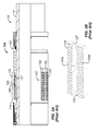
- FIGS 1A-1B show a T-style slip mechanism 10 according to the prior art.
- the mechanism 10 includes several slip components, such as T-style slips 20, a cone 30, and a cage 40-each of which dispose on a mandrel 14 of a packer 12 or the like.
- the T-style slips 20 have wickered ends 24 and T-shaped ends 28 interconnected by necks 22.
- Slip slots 42 in the cage 40 hold the T-shaped ends 28, while slots 32 in the cone 30 hold the wickered ends 24.
- the wickered ends 24 have shoulders or ledges 25 ( Fig. 1A ) that ride in grooves 35 in the cage's slots 32.
- the T-style slips 20 set into the casing wall when the cone 30 is mechanically or hydraulically moved closer to the slip cage 40. For this reason, the slips' wickered ends 24 have ramped edges 27 that are pushed by the cone 30.
- FIGS 2A-2B show a hydro-style slip mechanism 110 according to the prior art.
- the mechanism 110 includes several slip components, such as hydro-style slips 120, a cone 130, and a cage 140-each of which dispose on a mandrel 14 of a packer 12 or the like.
- the hydro-style slips 120 fit around the mandrel 14 and have wickered faces 124a-b that fit through slip slots 142 in the cage 140.
- a spring 160 disposes in a central passage 122 along the length of the slip 120 and sits beneath a central band 144 in the slip slots 142.
- This spring which is usually a leaf style spring, biases the slip 120 to a retracted condition when the cone 130 has been pulled out of the set position.
- the hydro-style slip 120 has wickers 126 on its outer face that can set into the surrounding casing wall (not shown).
- the cone 130 is moved (typically by hydraulic activation) further beneath the slip cage 140 and also beneath the hydro-style slips 120.
- a ramped edge 137 on the cone 130 pushes against the ramped end 127 of the slip 120. Therefore, the cone 130 should slide beneath the slip cage 140 to push the slips 120 through the slip slots 142.
- Figures 3A-3B show an arrow-style slip mechanism 210 according to the prior art.
- This mechanism 210 includes several slip components, such as arrow-style slips 220, a cone 230, and a cage 240-each of which dispose on the mandrel 14 of a packer 12 or the like.
- the arrow-style slips 220 fit around the mandrel 14 and have wickered ends 224 and fitted ends 228 interconnected by necks 222.
- the fitted ends 228 fit in comparably shaped slots 242 in the cage 240, while the necks 222 fit under a shoulder area 244 on the edge of the cage 240.
- the arrow-style slip 220 sets into the casing wall when the cone 230 is mechanically or hydraulically moved closer to the slip cage 240.
- the wickered end 224 of the slip 220 includes a ramped edge 227 on its inner side.
- the cones ramped edge 237 engages the slip's ramped ends 227, pushing the slip's wickered end 224 into the casing wall.
- the wickers 226 on the slip's wickered end 224 set into the surrounding casing wall (not shown). Whether the slips 220 are set or not, the cage 240 remains connected to the fitted ends 228 of the arrow-style slip 222 by virtue of these slip slots 242.
- slips bite or lock in a tool; the prime example being a packer slip used to lock the packer in a selected position in casing or wellbore.
- the problem is to make the slips easier to remove by milling or drilling techniques thereby cutting well construction, completion time, and costs.
- slips have been made from gray and ductile types of cast irons. These cast irons are more readily millable/drillable, but still require significant milling/drilling time. More recently, slips have been made with ceramic biting elements glued in composite slip bases. The work in composite slips is promising but unproven because there may be ductility issues with the composite slip base materials. Thus, these solutions, at this point, have provided less than an ideal solution.
- the subject matter of the present disclosure is directed to overcoming, or at least reducing the effects of, one or more of the problems set forth above.
- a slip component for a downhole tool has a bearing surface that is hard surface treated.
- the slip component can be a slip or other component of a slip mechanism used on a packer, bridge plug, or other downhole tool.
- the slip component can be a slip, a cone, and/or a cage of a slip mechanism of the downhole tool and can even include a portion of a mandrel of the downhole tool adjacent the slip mechanism.
- the slip component is composed of a metallic base material having a relatively low melting point compared with steel.
- the metallic base material of the slip component can be magnesium, aluminum, an aluminum alloy, or a magnesium alloy.
- the aluminum alloy for the slip component can be a series 6000 aluminum alloy, such as the aluminum alloy 6061-T6.
- At least the bearing surface of the slip component is positioned relative to an electrospark deposition apparatus, which has an electrode composed of a selected external material for depositing on the slip component.
- the bearing surface can be a gripping surface of a slip used to engage a downhole tubular, although any bearing surface subject to wear, friction, etc. can benefit from the disclosed techniques.
- an external layer is bonded at least on the bearing surface by electrospark depositing the external material of the electrode to the metallic base material of the slip component.
- a metallurgical bond is formed between the external material with the metallic base material in which a bulk temperature of the slip component is maintained well below the melting point of the base material. In this way, the bulk temperature of the slip component can be maintained below a temperature where a design strength level of the slip component is compromised.
- Various external materials can be used for electrosparking, including, but not limited to, a metallic material, a cermet material, a ceramic material, a hard surfacing alloy, a cobalt-based hard surfacing alloy, an iron-based hard surfacing alloy, a nickel-based hard surfacing alloy, a stainless steel, a nickel super alloy, and a cobalt base alloy, such as a Stellite ® metal alloy.
- STELLITE is a registered trademark of DELORO STELLITE HOLDINGS CORPORATION
- the hard surfacing alloy can be UNS R30001, UNS R30035, and UNS N99646 available from Stellite Coatings of Goshen, Indiana.
- a hardness of at least a portion of the external layer can be increased further by surface treating the external layer to induce compressive stresses or relieve tensile stresses.
- surface treating the external layer can involve using a mechanical process, such as peening, shot peening, and burnishing, or can involve using a non-mechanical process, such as ultrasonic peening and laser peening.
- hard surfacing the slip component can involve an intermediate stage in which at least the bearing surface is positioned relative to an ion sputtering apparatus before electrosparking an external layer on the slip component.
- an intermediate layer is bonded onto at least the bearing surface by ion sputtering an intermediate material onto the metallic base material of the slip component. Then, at least the bearing surface is positioned relative to the electrospark deposition apparatus so that an external layer can be bonded at least on the intermediate layer.
- An aspect of the invention relates to a method of hard surfacing a slip component for a downhole tool, the slip component having a bearing surface and being composed of a base material, the base material being metallic, the method comprising:
- Electrospark depositing the external material to the base material may comprise forming a metallurgical bond between the external material with the metallic base material.
- Forming the metallurgical bond may comprise maintaining a bulk temperature of the slip component below a melting point of the base material.
- Maintaining the bulk temperature of the slip component below the melting point may comprise maintaining the bulk temperature of the slip component below a temperature where a design strength level of the slip component is compromised.
- the base material of the slip component may be selected from the group consisting of magnesium, aluminum, aluminum alloys, and magnesium alloys.
- the aluminum alloy may be selected from the group consisting of a series 6000 aluminum alloy.
- the aluminum alloy may be an aluminum alloy 6061-T6.
- the electrosparked external material may comprise at least one of a metallic material, a cermet material, a ceramic material, a hard surfacing alloy, a cobalt-based hard surfacing alloy, an iron-based hard surfacing alloy, a nickel-based hard surfacing alloy, a stainless steel, a nickel super alloy, and a cobalt base alloy.
- the cobalt base alloy may be selected from the group consisting of UNS R30001, UNS R30035, and UNS N99646.
- the method may further comprise increasing a hardness of at least a portion of the extenal layer by surface treating the external layer to induce compressive stresses or relieve tensile stresses.
- Surface treating the external layer may comprise:
- the slip component may comprise at least one slip of a slip mechanism of the downhole tool, and the bearing surface may comprise a gripping surface of the at least one slip.
- the slip component is selected from the group consisting of a slip, a cone, and a cage of a slip mechanism of the downhole tool.
- the slip component may comprise at least a portion of a mandrel of the downhole tool adjacent a slip mechanism of the downhole tool.
- slip component for a downhole tool
- the slip component being composed of a base material and having a bearing surface, the base material being metallic, at least the bearing surface treated by:
- a further aspect of the present invention relates to a method of hard surfacing a slip component for a downhole tool, the slip component having a bearing surface and being composed of a base material, the base material being metallic, the method comprising:
- Positioning at least the bearing surface of the slip component for the hard surface treatment may comprise positioning at least the bearing surface relative to an ion sputtering apparatus.
- Positioning at least the bearing surface of the slip component for the hard surface treatment may further comprise positioning at least the bearing surface relative to an electrospark deposition apparatus.
- Electrospark depositing the external material to at least the intermediate material may comprise forming a metallurgical bond between the external layer with the intermediate layer.
- Forming the metallurgical bond may comprise maintaining a bulk temperature of the slip component below a melting point of the base material.
- Maintaining the bulk temperature of the slip component below the melting point may comprise maintaining the bulk temperature of the slip component below a temperature where a design strength level of the slip is compromised.
- the slip component may comprise at least one slip of a slip mechanism of the downhole tool, and wherein the bearing surface may comprise a gripping surface of the at least one slip.
- the slip component may be selected from the group consisting of a slip, a cone, and a cage of a slip mechanism of the downhole tool.
- the slip component may comprise at least a portion of a mandrel of the downhole tool adjacent a slip mechanism of the downhole tool.
- a still further aspect of the present invention relates to a slip component for a downhole tool, the slip component being composed of a base material and having a bearing surface, the base material being metallic, at least the bearing surface treated by:
- FIG. 4 illustrates a schematic of an electrospark deposition system 400 according to the present disclosure for hard surface treating a metallic slip component of a downhole tool.
- Electrospark deposition is also referred to as spark hardening, electrospark toughening, electrospark alloying, pulse fusion surfacing and pulsed electrode surfacing.
- spark hardening also referred to as spark hardening, electrospark toughening, electrospark alloying, pulse fusion surfacing and pulsed electrode surfacing.
- electrospark deposition is a pulsed micro-welding process that uses rapid electrical power discharges to accomplish metal transfer from an electrode to a contacting surface.
- Other "impulse" technologies such as percussion welding and magnetic pulse welding also transfer minute quantities of material using "pulsing" to accomplish metal transfer.
- Electrospark deposition system 400 includes a control unit 410 that connects to a workpiece 320 and to an electrode 414.
- the workpiece 320 is a metallic slip component, e.g., a component of a slip mechanism used on a downhole tool, such as a packer, bridge plug, or the like, and more particularly, the workpiece 320 is a slip, such as an arrow-style slip, for a slip mechanism.
- a slip such as an arrow-style slip, for a slip mechanism.
- the electrode 414 is positioned and moved with respect to the slip 320.
- the parameters associated with electrode 414 and power from control unit 410 is controlled such that controlled electrostatic forces are established in the electrode tip 424 and in the slip 320 and specifically at a location 426 where it is desired to deposit material by the electrospark process.
- the electrode 414 is positioned with respect to the slip 320 such that the electrostatic force is substantially equal to a glow discharge condition.
- the electrode 414 is then advanced into contact with the surface 324 of the slip 320 and then quickly withdrawn to draw a spark arc between the electrode 414 and the surface 324. It is preferred that the process is controlled such that no significant current flows between electrode 414 and slip 320. In this manner, the only significant heating of slip 320 is caused by the spark arc itself. This heating will occur substantially only in the area where the electrode 414 has touched the surface 324, and air quenching at this point can quickly occur, as taught in U.S. Patent No. 4,551,603 .
- the parameters are also controlled such that the spark arc has sufficient energy to melt a portion of the electrode 414.
- the electrode's tip 424 is the anode and preferably has a very small area so that the arc spark can melt the tip 424 of the electrode 414 without significantly heating the slip 320.
- a deposit of electrode material 434 is left on the slip's surface 324. This process is repeated until the desired areas of slip 320 have had electrode material 434 deposited thereon. These deposits may be thought of as the transfer of minute quantities of a desired surfacing material from a contacting electrode 414 to the surface 324 of the slip 320. These microwelds will overlap, yielding a complete new hardened surface that is metallurgically bonded to the underlying material of the slip 320.
- FIG. 5A shows an example of a slip component 320, such as a T-slip, composed of a metallic material
- FIG. 5B is a detailed view of the surface 324 of the metallic slip 320 after the electrospark deposition system such as illustrated in FIG. 4 has deposited a hard exterior layer using electrosparking to at least a bearing surface of the component.
- the slip 320 is composed of a metallic material and can be more particularly composed of magnesium, aluminum, aluminum alloy, or magnesium alloy.
- aluminum alloys of the 6000 series may be favorable for surface treatment using the techniques disclosed herein.
- One preferred aluminum alloy is Aluminum 6061-T6 for a slip 320 hard surfaced using the disclosed techniques. Most aluminum alloys are good candidates; the defining factor is meeting a minimum design strength of the slip 320 at application temperatures experienced downhole.
- electro spark deposition involves the transfer of minute molten droplets of the desired surfacing material, such as a metal, from the contacting electrode (414) to the surface 324 of the slip 320. These micro-welds overlap, yielding a complete new surface.
- the electrosparked material is bonded to the metallic substrate of the slip's surface 324, a metallurgical bond is formed. This is in contrast to other low heat input processes, such as arc-spraying or high velocity oxy-fuel processes.
- the electrode deposit material can include a metallic material, a cermet material, or a ceramic material, and can include metal carbides, nitrides, or borides.
- metal carbides nitrides, or borides.
- cemented tungsten carbide which includes a metal carbide and a matrix ductile metal.
- a hard surfacing alloy such as a cobalt, iron, or nickel-based hard surfacing alloy, may also be used. Specific examples of these alloys include UNS R30001, UNS R30035, or UNS N99646.
- nickel alloys such as Ni-super alloys
- stainless steel compositions such as martensitic stainless steels
- cobalt base alloy e.g., Stellite ®
- the material properties of the electrosparked layer 350 can be further improved by mechanical working, such as peening, shot peening, and burnishing.
- mechanical working such as peening, shot peening, and burnishing.
- Non-mechanical processes can also be used, such as ultrasonic peening and laser peening.
- the further working can increase the hardness of at least a portion of the layer of the electrosparked material by inducing compressive stresses or relieving tensile stresses.
- the electrospark process has an extremely low heat input. It is believed that the process results in a maximum temperature rise on the order of a few degrees C away from the joining interface of the electrode 414 and the slip's surface 324. This low heat input process, therefore, does not alter the integrity of the aluminum slip 320 but results in a metallurgical bond between the hard exterior layer 350 and the aluminum slip 320. It is believed that the disclosed process results in a hardened zone that is not limited to a low bond strength, such as 12000 psi and less.
- FIG. 6 illustrates a slip 320, such as an arrow-style slip, wherein the disclosed process has been applied to the biting edges or surfaces 326, also referred to as gripping surfaces, of the slip 320.
- Other bearing surfaces of the slip 320 may benefit from the disclosed hard surface treatment of the present disclosure.
- the ramp 327 on the end of the slip 320 can be treated according to the present disclosure.
- the hard exterior layer primarily metallurgically bonded to the slip component below can provide improved wear resistance, erosion resistance, and also resistance to cutting and deformation so that any bearing surface of the slip component can benefit from the disclosed treatment.
- the disclosed process can also be used to harden various types of slips, such as T-slips, hydro-style slips, or arrow style slips.
- the disclosed process can also be used to harden any bearing surface of a slip component or even a downhole tool, such as a packer, made at least in part from an aluminum material.
- the disclosed process can be used for cones, gauge rings, mandrel, and similar components of a downhole tool.
- FIGS. 7, 8A, 8B and 9 illustrate an alternative embodiment of the present disclosure wherein an intermediate layer is ion sputtered onto a slip component before the hard metallic exterior layer is electrospark deposited.
- FIG. 7 illustrates a schematic representation of an ion sputtering system 700 according to the present disclosure.
- Ion sputtering system 700 includes a chamber C, an ion gun 710, and a target 720 for applying an intermediate layer to a workpiece 320, which again is an aluminum slip for a downhole tool or packer in the present example.
- Vacuum sputtering accomplished by the ion sputtering system 700 is a well-established method of depositing a thin layer of bond material upon a substrate.
- a beam of ions is fired from the ion gun 710 at the target 720 in the chamber C.
- the chamber C is maintained at substantially a vacuum.
- the resulting impact of the ions against the target 720 causes atoms of the target material to be ejected therefrom and to be deposited onto the surface 324 of the slip 320.
- materials for the target 720 include nickel, iron, cobalt, gold, silver and alloys or combinations of these materials.
- FIGS. 8A-8B illustrates the slip 320 after the ion sputtering system 700 has deposited an intermediate layer 800 using ion sputtering to the surface 324 of the slip 320.
- the ion sputtered metallic layer 800 can have a thickness on the order of five thousand to ten thousand angstroms. Ion sputtering is the preferred process for applying the metallic layer 800 because of the low heat input the ion sputtering process has on the base material, which in this case is the aluminum gripping section 326 of the slip 320. A process with a high heat input could damage the underlying material of the aluminum gripping section 326 because the heat input may melt the underlying material.
- processes other than ion sputtering could be used if they have sufficiently low heat input so as not to melt or damage the underlying material of the aluminum slip 320.
- the ion sputtering process should not raise the temperature of the underlying base material above the solidus (i.e., the temperature at which the materials begins to melt). In many cases, the solidus is less than the melting point. This means that the underlying aluminum base materials' physical properties, such as hardness, may be impaired before the material has been heated to its melting point.
- the slip 320 can then be treated with the electrospark process disclosed previously with reference to Figure 4 to apply an external, electrosparked layer.
- FIGS. 9A-9B illustrates the slip 320 after electrosparking a metallic substrate layer 900 to the intermediate layer 800 deposited previously with the ion sputtering.
- the electrosparked layer 900 can be applied to the biting edges or surfaces, also referred to as gripping surface 326, of the slip 320, although other portions of the slip 320 may be treated as noted herein.
Landscapes
- Engineering & Computer Science (AREA)
- Mining & Mineral Resources (AREA)
- Life Sciences & Earth Sciences (AREA)
- Geology (AREA)
- Chemical & Material Sciences (AREA)
- Physics & Mathematics (AREA)
- Mechanical Engineering (AREA)
- Fluid Mechanics (AREA)
- General Life Sciences & Earth Sciences (AREA)
- Geochemistry & Mineralogy (AREA)
- Environmental & Geological Engineering (AREA)
- Chemical Kinetics & Catalysis (AREA)
- Materials Engineering (AREA)
- Metallurgy (AREA)
- Organic Chemistry (AREA)
- Plasma & Fusion (AREA)
- General Engineering & Computer Science (AREA)
- Sliding-Contact Bearings (AREA)
- Physical Vapour Deposition (AREA)
- Other Surface Treatments For Metallic Materials (AREA)
Abstract
Description
- This application is filed concurrently with U.S. Appl. , having Attorney Docket No. 205-0326US and entitled "Hard Surfacing Non-Metallic Slip Components for Downhole Tools," which is incorporated herein by reference in its entirety.
- Downhole tools use slips to engage a casing and hold a downhole tool in place. For example, packers are a type of downhole tool that uses slips. Packers are used in oil and gas wells primarily to isolate different production zones. On the packer, a slip provides a frictional hold between the packer and casing or wellbore that helps keep the packer in place when subjected to high pressure, high temperature, and applied forces. The packer and associated slip is either permanent or retrievable.
- Permanent packers are usually less expensive to manufacture and are typically capable of withstanding high pressure and temperature. In contrast, a retrievable packer can be "unset" by using hydraulic or mechanical means. After the packer is "unset," it can be brought uphole with tubing or a work string. Because it is designed to be reusable, a retrievable packer is, typically, more complex and has more mechanical parts.
- Because it is permanent, a permanent packer is typically destroyed by milling or drilling to remove it. In other words, the permanent packer is designed for a single use and is destroyed to remove it. Thus, it is desirable to construct a permanent packer from materials that are more readily milled or drilled. Examples of materials that are more readily milled or drilled are made from non-metallic materials, such as composites, ceramics and plastics. Plastics such as ultra-high-molecular-weight polyethylene (UHMW), polytetrafluroethylene (PTFE) or similar engineering grade plastics can be used because of their high molecular weight and long molecular chains, although other thermoplastic polyethylenes might also be used.
- Broadly speaking, more readily milled/drilled materials are weaker and are therefore less capable of carrying a load. Correspondingly, forming a permanent packer from more sturdy metallic materials makes the permanent packer stronger. However, the added strength means that it is more difficult to mill or drill the permanent packer to remove it. Added strength to the packer means that additional rig time is required to mill or drill the packer to remove it. Thus, there is an inherent contradiction between using permanent packers composed of metallic materials because it is significantly more time consuming to mill or drill when they are no longer needed. Because rig time is expensive, the added expense of additional rig time can equal or exceed the savings of using a permanent packer as opposed to a retrievable packer.
- The use of more durable metallic materials can also cause a problem known as "bit tracking" to occur when a drilling or milling a metallic material. During bit tracking, the drill bit used to mill out the tool stays on one path and no longer cuts the material to be drilled or milled. When this happens, it is appropriate to pick up the bit and rapidly recontact the material being drilled. During bit tracking, some material may be removed, but in actuality the drill bit is merely wearing against the surface of the downhole tool. Essentially, during bit tracking, the drill bit is rotating, but it is not appropriately cutting the packer or other material to be removed. Unfortunately, it might not be readily apparent to operators at the surface that bit tracking is occurring because the drill bit continues to rotate normally, even though it is not drilling or milling the packer or other material to be drilled.
- A downhole tool may be used when it is desirable to seal tubing or other pipe in the casing or wellbore of the well, such as when it is desired to pump cement or other slurry out into a formation. In this situation, it is appropriate to seal the tubing with respect to the well casing and to prevent the fluid pressure of the slurry from lifting the tubing out of the well. Packers, bridge plugs, and the like are designed for these general purposes. Slip mechanisms are devices used on these downhole tools to contact the wellbore and hold the downhole tool in the wellbore without substantial movement, and as discussed above, to hold back fluid or pressure. Typically, the slip mechanism is used to contact the wellbore to hold the downhole tool in the wellbore without substantial movement.
- Current slip mechanisms used in the art include T-style, hydro-style, and arrow-style slip mechanisms, which are briefly discussed.
-
Figures 1A-1B show a T-style slip mechanism 10 according to the prior art. Themechanism 10 includes several slip components, such as T-style slips 20, acone 30, and a cage 40-each of which dispose on amandrel 14 of apacker 12 or the like. The T-style slips 20 have wickeredends 24 and T-shaped ends 28 interconnected bynecks 22.Slip slots 42 in thecage 40 hold the T-shaped ends 28, whileslots 32 in thecone 30 hold thewickered ends 24. In particular, thewickered ends 24 have shoulders or ledges 25 (Fig. 1A ) that ride ingrooves 35 in the cage'sslots 32. - The T-
style slips 20 set into the casing wall when thecone 30 is mechanically or hydraulically moved closer to theslip cage 40. For this reason, the slips'wickered ends 24 have rampededges 27 that are pushed by thecone 30. -
Figures 2A-2B show a hydro-style slip mechanism 110 according to the prior art. Themechanism 110 includes several slip components, such as hydro-style slips 120, acone 130, and a cage 140-each of which dispose on amandrel 14 of apacker 12 or the like. The hydro-style slips 120 fit around themandrel 14 and have wickeredfaces 124a-b that fit throughslip slots 142 in thecage 140. Aspring 160 disposes in acentral passage 122 along the length of theslip 120 and sits beneath a central band 144 in theslip slots 142. This spring, which is usually a leaf style spring, biases theslip 120 to a retracted condition when thecone 130 has been pulled out of the set position. As shown in the set position, however, the hydro-style slip 120 haswickers 126 on its outer face that can set into the surrounding casing wall (not shown). - To set the hydro-
style slip 120 into the casing wall, thecone 130 is moved (typically by hydraulic activation) further beneath theslip cage 140 and also beneath the hydro-style slips 120. A rampededge 137 on thecone 130 pushes against the rampedend 127 of theslip 120. Therefore, thecone 130 should slide beneath theslip cage 140 to push theslips 120 through theslip slots 142. -
Figures 3A-3B show an arrow-style slip mechanism 210 according to the prior art. Thismechanism 210 includes several slip components, such as arrow-style slips 220, acone 230, and a cage 240-each of which dispose on themandrel 14 of apacker 12 or the like. The arrow-style slips 220 fit around themandrel 14 and have wickeredends 224 and fittedends 228 interconnected bynecks 222. The fittedends 228 fit in comparablyshaped slots 242 in thecage 240, while thenecks 222 fit under ashoulder area 244 on the edge of thecage 240. The arrow-style slip 220 sets into the casing wall when thecone 230 is mechanically or hydraulically moved closer to theslip cage 240. In particular, thewickered end 224 of theslip 220 includes a rampededge 227 on its inner side. When thecone 230 is moved toward thecage 240, the cones rampededge 237 engages the slip's rampedends 227, pushing the slip's wickeredend 224 into the casing wall. When theslip 220 sets, thewickers 226 on the slip's wickeredend 224 set into the surrounding casing wall (not shown). Whether theslips 220 are set or not, thecage 240 remains connected to the fittedends 228 of the arrow-style slip 222 by virtue of theseslip slots 242. - The requirements for slips are that they bite or lock in a tool; the prime example being a packer slip used to lock the packer in a selected position in casing or wellbore. The problem is to make the slips easier to remove by milling or drilling techniques thereby cutting well construction, completion time, and costs.
- The prior art slips have been made from gray and ductile types of cast irons. These cast irons are more readily millable/drillable, but still require significant milling/drilling time. More recently, slips have been made with ceramic biting elements glued in composite slip bases. The work in composite slips is promising but unproven because there may be ductility issues with the composite slip base materials. Thus, these solutions, at this point, have provided less than an ideal solution.
- In addition, it is known to harden the surface of an aluminum metallic packer by anodizing the surface to form an anodized metallic coating. However, this is problematic because anodization has been found to produce very thin coatings of only a few angstroms or microns. Because this is a relatively thin layer, the slip cannot readily adhere with the substrate. Ion sputtering has also been used to form a metallic coating. However, this also produces only a thin substrate on the order of a few angstroms or microns, which has also been found to lack sufficient strength.
- The subject matter of the present disclosure is directed to overcoming, or at least reducing the effects of, one or more of the problems set forth above.
- A slip component for a downhole tool has a bearing surface that is hard surface treated. The slip component can be a slip or other component of a slip mechanism used on a packer, bridge plug, or other downhole tool. In fact, the slip component can be a slip, a cone, and/or a cage of a slip mechanism of the downhole tool and can even include a portion of a mandrel of the downhole tool adjacent the slip mechanism. Either way, the slip component is composed of a metallic base material having a relatively low melting point compared with steel. For example, the metallic base material of the slip component can be magnesium, aluminum, an aluminum alloy, or a magnesium alloy. In particular, the aluminum alloy for the slip component can be a series 6000 aluminum alloy, such as the aluminum alloy 6061-T6.
- To hard surface treat the slip component, at least the bearing surface of the slip component is positioned relative to an electrospark deposition apparatus, which has an electrode composed of a selected external material for depositing on the slip component. The bearing surface can be a gripping surface of a slip used to engage a downhole tubular, although any bearing surface subject to wear, friction, etc. can benefit from the disclosed techniques. Using the electrospark deposition apparatus, an external layer is bonded at least on the bearing surface by electrospark depositing the external material of the electrode to the metallic base material of the slip component.
- During the electrospark deposition of the external material to the base material, a metallurgical bond is formed between the external material with the metallic base material in which a bulk temperature of the slip component is maintained well below the melting point of the base material. In this way, the bulk temperature of the slip component can be maintained below a temperature where a design strength level of the slip component is compromised.
- Various external materials can be used for electrosparking, including, but not limited to, a metallic material, a cermet material, a ceramic material, a hard surfacing alloy, a cobalt-based hard surfacing alloy, an iron-based hard surfacing alloy, a nickel-based hard surfacing alloy, a stainless steel, a nickel super alloy, and a cobalt base alloy, such as a Stellite® metal alloy. (STELLITE is a registered trademark of DELORO STELLITE HOLDINGS CORPORATION). As some particular examples, the hard surfacing alloy can be UNS R30001, UNS R30035, and UNS N99646 available from Stellite Coatings of Goshen, Indiana.
- A hardness of at least a portion of the external layer can be increased further by surface treating the external layer to induce compressive stresses or relieve tensile stresses. For example, surface treating the external layer can involve using a mechanical process, such as peening, shot peening, and burnishing, or can involve using a non-mechanical process, such as ultrasonic peening and laser peening.
- In a further embodiment, hard surfacing the slip component can involve an intermediate stage in which at least the bearing surface is positioned relative to an ion sputtering apparatus before electrosparking an external layer on the slip component. In this embodiment, an intermediate layer is bonded onto at least the bearing surface by ion sputtering an intermediate material onto the metallic base material of the slip component. Then, at least the bearing surface is positioned relative to the electrospark deposition apparatus so that an external layer can be bonded at least on the intermediate layer.
- An aspect of the invention relates to a method of hard surfacing a slip component for a downhole tool, the slip component having a bearing surface and being composed of a base material, the base material being metallic, the method comprising:
- positioning at least the bearing surface of the slip component relative to an electrospark deposition apparatus; and
- bonding an external layer at least on the bearing surface by electrospark depositing an external material to the base material.
- Electrospark depositing the external material to the base material may comprise forming a metallurgical bond between the external material with the metallic base material.
- Forming the metallurgical bond may comprise maintaining a bulk temperature of the slip component below a melting point of the base material.
- Maintaining the bulk temperature of the slip component below the melting point may comprise maintaining the bulk temperature of the slip component below a temperature where a design strength level of the slip component is compromised.
- The base material of the slip component may be selected from the group consisting of magnesium, aluminum, aluminum alloys, and magnesium alloys.
- The aluminum alloy may be selected from the group consisting of a series 6000 aluminum alloy.
- The aluminum alloy may be an aluminum alloy 6061-T6.
- The electrosparked external material may comprise at least one of a metallic material, a cermet material, a ceramic material, a hard surfacing alloy, a cobalt-based hard surfacing alloy, an iron-based hard surfacing alloy, a nickel-based hard surfacing alloy, a stainless steel, a nickel super alloy, and a cobalt base alloy.
- The cobalt base alloy may be selected from the group consisting of UNS R30001, UNS R30035, and UNS N99646.
- The method may further comprise increasing a hardness of at least a portion of the extenal layer by surface treating the external layer to induce compressive stresses or relieve tensile stresses.
- Surface treating the external layer may comprise:
- using a mechanical process selected from the group consisting of peening, shot peening, and burnishing; or
- using a non-mechanical process selected from the group consisting of ultrasonic peening and laser peening.
- The slip component may comprise at least one slip of a slip mechanism of the downhole tool, and the bearing surface may comprise a gripping surface of the at least one slip.
- The slip component is selected from the group consisting of a slip, a cone, and a cage of a slip mechanism of the downhole tool.
- The slip component may comprise at least a portion of a mandrel of the downhole tool adjacent a slip mechanism of the downhole tool.
- Another aspect of the invention relates to a slip component for a downhole tool, the slip component being composed of a base material and having a bearing surface, the base material being metallic, at least the bearing surface treated by:
- positioning at least the bearing surface relative to an electrospark deposition apparatus; and
- bonding an external layer at least on the bearing surface by electrospark depositing an external material to the base material.
- A further aspect of the present invention relates to a method of hard surfacing a slip component for a downhole tool, the slip component having a bearing surface and being composed of a base material, the base material being metallic, the method comprising:
- positioning at least the bearing surface of the slip component for hard surface treatment;
- bonding an intermediate layer onto at least the bearing surface by ion sputtering an intermediate material onto metallic base material; and
- bonding an external layer at least on the intermediate layer by electrospark depositing an external material to at least the intermediate material of the intermediate layer.
- Positioning at least the bearing surface of the slip component for the hard surface treatment may comprise positioning at least the bearing surface relative to an ion sputtering apparatus.
- Positioning at least the bearing surface of the slip component for the hard surface treatment may further comprise positioning at least the bearing surface relative to an electrospark deposition apparatus.
- Electrospark depositing the external material to at least the intermediate material may comprise forming a metallurgical bond between the external layer with the intermediate layer.
- Forming the metallurgical bond may comprise maintaining a bulk temperature of the slip component below a melting point of the base material.
- Maintaining the bulk temperature of the slip component below the melting point may comprise maintaining the bulk temperature of the slip component below a temperature where a design strength level of the slip is compromised.
- The slip component may comprise at least one slip of a slip mechanism of the downhole tool, and wherein the bearing surface may comprise a gripping surface of the at least one slip.
- The slip component may be selected from the group consisting of a slip, a cone, and a cage of a slip mechanism of the downhole tool.
- The slip component may comprise at least a portion of a mandrel of the downhole tool adjacent a slip mechanism of the downhole tool.
- A still further aspect of the present invention relates to a slip component for a downhole tool, the slip component being composed of a base material and having a bearing surface, the base material being metallic, at least the bearing surface treated by:
- positioning at least the bearing surface of the slip component for hard surface treatment;
- bonding an intermediate layer onto at least the bearing surface by ion sputtering an intermediate material onto the metallic base material; and
- bonding an external layer at least on the intermediate layer by electrospark depositing an external material to at least the intermediate material of the intermediate layer.
- The foregoing summary is not intended to summarize each potential embodiment or every aspect of the present disclosure.
-
-
FIG. 1A illustrates a partial cross-section of a downhole tool having a T-style slip mechanism according to the prior art. -
FIG 1B illustrates a perspective view of the T-style slip ofFIG. 1A . -
FIG. 2A illustrates a partial cross-section of a downhole tool having a hydro-style slip mechanism according to the prior art. -
FIG. 2B illustrates a perspective view of the hydro-style slip ofFIG. 2A . -
FIG. 3A illustrates a partial cross-section of a downhole tool having an arrow-style slip mechanism according to the prior art. -
FIG. 3B illustrates a perspective view of an arrow style slip ofFIG. 3A . -
FIG. 4 illustrates a schematic representation of an electrospark deposition system surface treating a slip component according to the present disclosure. -
FIG. 5A illustrates a slip component after the electrospark deposition system, such as illustrated inFIG. 4 , has deposited a hard external layer using electrosparking to at least a bearing surface of the component. -
FIG. 5B illustrates a detailed view of the slip component ofFIG. 5A . -
FIG. 6 illustrates another slip component having surface treatment of the present disclosure applied to the component's gripping surface. -
FIG. 7 illustrates a schematic representation of an ion sputtering system used in an alternative embodiment of the present disclosure to surface treat a slip component. -
FIG. 8A illustrates a slip component after the ion sputtering system such as illustrated inFIG. 7 has deposited a thin metallic substrate bond layer using ion sputtering to at least a bearing surface of the component. -
FIG. 8B illustrates illustrated detailed view of the slip component inFIG. 8A . -
FIGS. 9A and 9B illustrate the slip component ofFigs. 8A-8B after the electrospark deposition system such as illustrated inFIG. 4 has deposited a hard exterior layer using electrosparking to the metallic substrate bond layer. -
FIG. 4 illustrates a schematic of anelectrospark deposition system 400 according to the present disclosure for hard surface treating a metallic slip component of a downhole tool. Electrospark deposition is also referred to as spark hardening, electrospark toughening, electrospark alloying, pulse fusion surfacing and pulsed electrode surfacing. Broadly speaking, electrospark deposition is a pulsed micro-welding process that uses rapid electrical power discharges to accomplish metal transfer from an electrode to a contacting surface. Other "impulse" technologies, such as percussion welding and magnetic pulse welding also transfer minute quantities of material using "pulsing" to accomplish metal transfer. -
Electrospark deposition system 400 includes acontrol unit 410 that connects to aworkpiece 320 and to anelectrode 414. In this example, theworkpiece 320 is a metallic slip component, e.g., a component of a slip mechanism used on a downhole tool, such as a packer, bridge plug, or the like, and more particularly, theworkpiece 320 is a slip, such as an arrow-style slip, for a slip mechanism. Although the present examples focus on hard surface treatment of a slip, it will be appreciated with the benefit of the present disclosure that the disclosed hard surface treatment process of the present disclosure can be applied to any slip component (or any component) of a downhole having a bearing surface that can benefit from hard surface treatment. - In the
system 400, theelectrode 414 is positioned and moved with respect to theslip 320. The parameters associated withelectrode 414 and power fromcontrol unit 410 is controlled such that controlled electrostatic forces are established in theelectrode tip 424 and in theslip 320 and specifically at alocation 426 where it is desired to deposit material by the electrospark process. - More specifically, the
electrode 414 is positioned with respect to theslip 320 such that the electrostatic force is substantially equal to a glow discharge condition. Theelectrode 414 is then advanced into contact with thesurface 324 of theslip 320 and then quickly withdrawn to draw a spark arc between theelectrode 414 and thesurface 324. It is preferred that the process is controlled such that no significant current flows betweenelectrode 414 andslip 320. In this manner, the only significant heating ofslip 320 is caused by the spark arc itself. This heating will occur substantially only in the area where theelectrode 414 has touched thesurface 324, and air quenching at this point can quickly occur, as taught inU.S. Patent No. 4,551,603 . - During the electrospark process, the parameters are also controlled such that the spark arc has sufficient energy to melt a portion of the
electrode 414. The electrode'stip 424 is the anode and preferably has a very small area so that the arc spark can melt thetip 424 of theelectrode 414 without significantly heating theslip 320. As theelectrode 414 is withdrawn from theslip 320, a deposit ofelectrode material 434 is left on the slip'ssurface 324. This process is repeated until the desired areas ofslip 320 have hadelectrode material 434 deposited thereon. These deposits may be thought of as the transfer of minute quantities of a desired surfacing material from a contactingelectrode 414 to thesurface 324 of theslip 320. These microwelds will overlap, yielding a complete new hardened surface that is metallurgically bonded to the underlying material of theslip 320. -
FIG. 5A shows an example of aslip component 320, such as a T-slip, composed of a metallic material, andFIG. 5B is a detailed view of thesurface 324 of themetallic slip 320 after the electrospark deposition system such as illustrated inFIG. 4 has deposited a hard exterior layer using electrosparking to at least a bearing surface of the component. As noted above, theslip 320 is composed of a metallic material and can be more particularly composed of magnesium, aluminum, aluminum alloy, or magnesium alloy. In particular, aluminum alloys of the 6000 series may be favorable for surface treatment using the techniques disclosed herein. One preferred aluminum alloy is Aluminum 6061-T6 for aslip 320 hard surfaced using the disclosed techniques. Most aluminum alloys are good candidates; the defining factor is meeting a minimum design strength of theslip 320 at application temperatures experienced downhole. - In the detailed view of
FIG 5B , thesurface 324 of theslip 320 has been treated with theelectrospark deposition system 400 to deposit anelectrosparked layer 350 using electrosparking. As noted above, electro spark deposition involves the transfer of minute molten droplets of the desired surfacing material, such as a metal, from the contacting electrode (414) to thesurface 324 of theslip 320. These micro-welds overlap, yielding a complete new surface. In addition, because the electrosparked material is bonded to the metallic substrate of the slip'ssurface 324, a metallurgical bond is formed. This is in contrast to other low heat input processes, such as arc-spraying or high velocity oxy-fuel processes. - As noted above, a deposit of the electrode's material (434) is left on the slip's
surface 324 to form theelectrosparked layer 350. The electrode deposit material can include a metallic material, a cermet material, or a ceramic material, and can include metal carbides, nitrides, or borides. One preferred example is cemented tungsten carbide, which includes a metal carbide and a matrix ductile metal. Alternatively, a hard surfacing alloy, such as a cobalt, iron, or nickel-based hard surfacing alloy, may also be used. Specific examples of these alloys include UNS R30001, UNS R30035, or UNS N99646. In additional alternatives, nickel alloys, such as Ni-super alloys; stainless steel compositions, such as martensitic stainless steels; or cobalt base alloy (e.g., Stellite®) may be used. - In additional embodiments to improve hardness of the
electrosparked layer 350, the material properties of theelectrosparked layer 350 can be further improved by mechanical working, such as peening, shot peening, and burnishing. Non-mechanical processes can also be used, such as ultrasonic peening and laser peening. The further working can increase the hardness of at least a portion of the layer of the electrosparked material by inducing compressive stresses or relieving tensile stresses. - As noted above, the electrospark process has an extremely low heat input. It is believed that the process results in a maximum temperature rise on the order of a few degrees C away from the joining interface of the
electrode 414 and the slip'ssurface 324. This low heat input process, therefore, does not alter the integrity of thealuminum slip 320 but results in a metallurgical bond between thehard exterior layer 350 and thealuminum slip 320. It is believed that the disclosed process results in a hardened zone that is not limited to a low bond strength, such as 12000 psi and less. - As noted herein, various portions of a slip component can be hard surface treated according to the techniques disclosed herein. For example,
FIG. 6 illustrates aslip 320, such as an arrow-style slip, wherein the disclosed process has been applied to the biting edges or surfaces 326, also referred to as gripping surfaces, of theslip 320. Other bearing surfaces of theslip 320 may benefit from the disclosed hard surface treatment of the present disclosure. For example, theramp 327 on the end of theslip 320 can be treated according to the present disclosure. Accordingly, one skilled in the art will appreciate that the hard exterior layer primarily metallurgically bonded to the slip component below can provide improved wear resistance, erosion resistance, and also resistance to cutting and deformation so that any bearing surface of the slip component can benefit from the disclosed treatment. - As also noted above, the disclosed process can also be used to harden various types of slips, such as T-slips, hydro-style slips, or arrow style slips. Indeed, the disclosed process can also be used to harden any bearing surface of a slip component or even a downhole tool, such as a packer, made at least in part from an aluminum material. For example, the disclosed process can be used for cones, gauge rings, mandrel, and similar components of a downhole tool.
-
FIGS. 7, 8A, 8B and9 illustrate an alternative embodiment of the present disclosure wherein an intermediate layer is ion sputtered onto a slip component before the hard metallic exterior layer is electrospark deposited. -
FIG. 7 illustrates a schematic representation of anion sputtering system 700 according to the present disclosure.Ion sputtering system 700 includes a chamber C, anion gun 710, and atarget 720 for applying an intermediate layer to aworkpiece 320, which again is an aluminum slip for a downhole tool or packer in the present example. Vacuum sputtering accomplished by theion sputtering system 700 is a well-established method of depositing a thin layer of bond material upon a substrate. According to the technique, a beam of ions is fired from theion gun 710 at thetarget 720 in the chamber C. Preferably, the chamber C is maintained at substantially a vacuum. The resulting impact of the ions against thetarget 720 causes atoms of the target material to be ejected therefrom and to be deposited onto thesurface 324 of theslip 320. Examples of materials for thetarget 720 include nickel, iron, cobalt, gold, silver and alloys or combinations of these materials. -
FIGS. 8A-8B illustrates theslip 320 after theion sputtering system 700 has deposited anintermediate layer 800 using ion sputtering to thesurface 324 of theslip 320. The ion sputteredmetallic layer 800 can have a thickness on the order of five thousand to ten thousand angstroms. Ion sputtering is the preferred process for applying themetallic layer 800 because of the low heat input the ion sputtering process has on the base material, which in this case is thealuminum gripping section 326 of theslip 320. A process with a high heat input could damage the underlying material of thealuminum gripping section 326 because the heat input may melt the underlying material. However, processes other than ion sputtering could be used if they have sufficiently low heat input so as not to melt or damage the underlying material of thealuminum slip 320. For its part, it is believed that the ion sputtering process should not raise the temperature of the underlying base material above the solidus (i.e., the temperature at which the materials begins to melt). In many cases, the solidus is less than the melting point. This means that the underlying aluminum base materials' physical properties, such as hardness, may be impaired before the material has been heated to its melting point. - After treatment with the ion sputtering process to apply the
intermediate layer 800, theslip 320 can then be treated with the electrospark process disclosed previously with reference toFigure 4 to apply an external, electrosparked layer. For example,FIGS. 9A-9B illustrates theslip 320 after electrosparking ametallic substrate layer 900 to theintermediate layer 800 deposited previously with the ion sputtering. As shown, theelectrosparked layer 900 can be applied to the biting edges or surfaces, also referred to as grippingsurface 326, of theslip 320, although other portions of theslip 320 may be treated as noted herein. - The foregoing description of preferred and other embodiments is not intended to limit or restrict the scope or applicability of the inventive concepts conceived of by the Applicants. It will be appreciated with the benefit of the present disclosure that features described above in accordance with any embodiment or aspect of the disclosed subject matter can be utilized, either alone or in combination, with any other described feature, in any other embodiment or aspect of the disclosed subject matter.
- In exchange for disclosing the inventive concepts contained herein, the Applicants desire all patent rights afforded by the appended claims. Therefore, it is intended that the appended claims include all modifications and alterations to the full extent that they come within the scope of the following claims or the equivalents thereof.
Claims (15)
- A method of hard surfacing a slip component for a downhole tool, the slip component having a bearing surface and being composed of a base material, the base material being metallic, the method comprising:positioning at least the bearing surface of the slip component for hard surface treatment at least relative to an electrospark deposition apparatus; andbonding an external layer at least on the bearing surface by electrospark depositing an external material.
- The method of claim 1, wherein bonding the external layer at least on the bearing surface by electrospark depositing the external material comprises:bonding the external layer at least on the bearing surface by electrospark depositing the external material directly to the base material.
- The method of claim 2, wherein electrospark depositing the external material to the base material comprises forming a metallurgical bond between the external material with the metallic base material.
- The method of claim 1, wherein bonding the external layer at least on the bearing surface by electrospark depositing the external material comprises:bonding an intermediate layer onto at least the bearing surface by ion sputtering an intermediate material onto metallic base material; andbonding the external layer at least on the intermediate layer by electrospark depositing the external material to at least the intermediate material of the intermediate layer.
- The method of claim 4, wherein positioning at least the bearing surface of the slip component for the hard surface treatment comprises positioning at least the bearing surface relative to an ion sputtering apparatus.
- The method of claim 5, wherein positioning at least the bearing surface of the slip component for the hard surface treatment further comprises positioning at least the bearing surface relative to the electrospark deposition apparatus.
- The method of claim 4, 5 or 6, wherein electrospark depositing the external material to at least the intermediate material comprises forming a metallurgical bond between the external layer with the intermediate layer.
- The method of claim 3 or 7, wherein forming the metallurgical bond comprises maintaining a bulk temperature of the slip component below a melting point of the base material, and optionally wherein maintaining the bulk temperature of the slip component below the melting point comprises maintaining the bulk temperature of the slip component below a temperature where a design strength level of the slip is compromised.
- The method of any preceding claim, wherein the slip component comprise at least one slip of a slip mechanism of the downhole tool, and wherein the bearing surface comprises a gripping surface of the at least one slip.
- The method of any preceding claim, wherein the slip component is selected from the group consisting of a slip, a cone, and a cage of a slip mechanism of the downhole tool.
- The method of any preceding claim, wherein the slip component comprises at least a portion of a mandrel of the downhole tool adjacent a slip mechanism of the downhole tool.
- The method of any preceding claim, wherein the base material of the slip component is selected from the group consisting of magnesium, aluminum, aluminum alloys, and magnesium alloys, optionally wherein the aluminum alloy is selected from the group consisting of a series 6000 aluminum alloy, and further optionally where the aluminum alloy is an aluminum alloy 6061-T6.
- The method of any preceding claim, wherein the electrosparked external material comprises at least one of a metallic material, a cermet material, a ceramic material, a hard surfacing alloy, a cobalt-based hard surfacing alloy, an iron-based hard surfacing alloy, a nickel-based hard surfacing alloy, a stainless steel, a nickel super alloy, and a cobalt base alloy, and optionally wherein the cobalt base alloy is selected from the group consisting of UNS R30001, UNS R30035, and UNS N99646.
- The method of any preceding claim, further comprising increasing a hardness of at least a portion of the external layer by surface treating the external layer to induce compressive stresses or relieve tensile stresses, and optionally wherein surface treating the external layer comprises:using a mechanical process selected from the group consisting of peening, shot peening, and burnishing; orusing a non-mechanical process selected from the group consisting of ultrasonic peening and laser peening.
- A slip component for a downhole tool, the slip component comprising at least a bearing surface treated by a method according to any one of the preceding claims.
Applications Claiming Priority (1)
| Application Number | Priority Date | Filing Date | Title |
|---|---|---|---|
| US13/762,207 US9273527B2 (en) | 2013-02-07 | 2013-02-07 | Hard surfacing metallic slip components for downhole tools |
Publications (2)
| Publication Number | Publication Date |
|---|---|
| EP2767668A2 true EP2767668A2 (en) | 2014-08-20 |
| EP2767668A3 EP2767668A3 (en) | 2015-12-23 |
Family
ID=50071449
Family Applications (1)
| Application Number | Title | Priority Date | Filing Date |
|---|---|---|---|
| EP14154190.4A Withdrawn EP2767668A3 (en) | 2013-02-07 | 2014-02-06 | Hard surfacing metallic slip components for downhole tools |
Country Status (6)
| Country | Link |
|---|---|
| US (1) | US9273527B2 (en) |
| EP (1) | EP2767668A3 (en) |
| CN (1) | CN103981520B (en) |
| AR (1) | AR094737A1 (en) |
| CA (1) | CA2841512C (en) |
| MX (1) | MX350975B (en) |
Cited By (1)
| Publication number | Priority date | Publication date | Assignee | Title |
|---|---|---|---|---|
| WO2021223024A1 (en) * | 2020-05-05 | 2021-11-11 | Huys Industries Limited | Welded surface coating using electro-spark discharge process |
Families Citing this family (13)
| Publication number | Priority date | Publication date | Assignee | Title |
|---|---|---|---|---|
| WO2014194234A1 (en) * | 2013-05-30 | 2014-12-04 | Frank's International, Llc | Coating system for tubular gripping components |
| US10876196B2 (en) | 2013-05-30 | 2020-12-29 | Frank's International, Llc | Coating system for tubular gripping components |
| US11584969B2 (en) | 2015-04-08 | 2023-02-21 | Metal Improvement Company, Llc | High fatigue strength components requiring areas of high hardness |
| US10619222B2 (en) | 2015-04-08 | 2020-04-14 | Metal Improvement Company, Llc | High fatigue strength components requiring areas of high hardness |
| US20160376869A1 (en) | 2015-06-23 | 2016-12-29 | Weatherford Technology Holdings, Llc | Self-Removing Plug for Pressure Isolation in Tubing of Well |
| CN109323207B (en) * | 2018-08-17 | 2021-07-09 | 郴州智上光电科技有限公司 | Graphene headlamp |
| US11541516B2 (en) | 2019-09-25 | 2023-01-03 | Snap-On Incorporated | Fastener retention and anti-camout tool bit |
| CN111235449A (en) * | 2020-01-15 | 2020-06-05 | 太原科技大学 | A kind of surface-enhanced LPSO-containing phase rapid degradation magnesium alloy and preparation method thereof |
| US11293244B2 (en) | 2020-02-28 | 2022-04-05 | Weatherford Technology Holdings, Llc | Slip assembly for a downhole tool |
| US11591881B2 (en) | 2021-03-17 | 2023-02-28 | Weatherford Technology Holdings, Llc | Cone for a downhole tool |
| CN114395661A (en) * | 2021-12-29 | 2022-04-26 | 贵州高峰石油机械股份有限公司 | Processing method for laser quenching of surface of slip of jar |
| US12467123B2 (en) * | 2023-10-09 | 2025-11-11 | Cnpc Usa Corporation | Boronized corrosion resistant alloy component for high pressure and high temperature oilfield applications |
| CN122374530A (en) * | 2023-10-09 | 2026-07-10 | 中国石油天然气集团公司休斯敦技术研究中心 | Bored corrosion-resistant alloy components for high-pressure, high-temperature oilfield applications |
Citations (3)
| Publication number | Priority date | Publication date | Assignee | Title |
|---|---|---|---|---|
| US4551603A (en) | 1971-04-02 | 1985-11-05 | Rocklin Isadore J | Device and method for surfacing a workpiece |
| US20040157066A1 (en) * | 2003-02-07 | 2004-08-12 | Arzoumanidis G. Alexis | Method of applying a hardcoating typically provided on downhole tools, and a system and apparatus having such a hardcoating |
| WO2008032872A1 (en) * | 2006-09-14 | 2008-03-20 | Sumitomo Metal Industries, Ltd. | Threaded joint for steel pipes |
Family Cites Families (12)
| Publication number | Priority date | Publication date | Assignee | Title |
|---|---|---|---|---|
| US5224540A (en) | 1990-04-26 | 1993-07-06 | Halliburton Company | Downhole tool apparatus with non-metallic components and methods of drilling thereof |
| US5897966A (en) * | 1996-02-26 | 1999-04-27 | General Electric Company | High temperature alloy article with a discrete protective coating and method for making |
| WO1998010899A1 (en) | 1996-09-13 | 1998-03-19 | Bangert Daniel S | Granular particle gripping surface |
| US6417477B1 (en) | 1999-06-08 | 2002-07-09 | Rolls-Royce Corporation | Method and apparatus for electrospark alloying |
| GB9922110D0 (en) | 1999-09-17 | 1999-11-17 | Nordiko Ltd | Ion beam vacuum sputtering apparatus and method |
| US6426476B1 (en) * | 2000-07-20 | 2002-07-30 | Battelle Memorial Institute | Laminated rare earth structure and method of making |
| US20030075340A1 (en) * | 2001-10-23 | 2003-04-24 | Khai Tran | Lubricant for use in a wellbore |
| US8220563B2 (en) * | 2008-08-20 | 2012-07-17 | Exxonmobil Research And Engineering Company | Ultra-low friction coatings for drill stem assemblies |
| US20110088891A1 (en) * | 2009-10-15 | 2011-04-21 | Stout Gregg W | Ultra-short slip and packing element system |
| US8579024B2 (en) * | 2010-07-14 | 2013-11-12 | Team Oil Tools, Lp | Non-damaging slips and drillable bridge plug |
| US9016364B2 (en) | 2010-11-23 | 2015-04-28 | Wireline Solutions, Llc | Convertible multi-function downhole isolation tool and related methods |
| US8397840B2 (en) * | 2012-01-31 | 2013-03-19 | Reusable Wearbands, Llc | Replaceable wear band for well drill pipe |
-
2013
- 2013-02-07 US US13/762,207 patent/US9273527B2/en not_active Expired - Fee Related
-
2014
- 2014-02-05 CA CA2841512A patent/CA2841512C/en not_active Expired - Fee Related
- 2014-02-06 EP EP14154190.4A patent/EP2767668A3/en not_active Withdrawn
- 2014-02-07 AR ARP140100413A patent/AR094737A1/en not_active Application Discontinuation
- 2014-02-07 MX MX2014001552A patent/MX350975B/en active IP Right Grant
- 2014-02-07 CN CN201410045338.9A patent/CN103981520B/en not_active Expired - Fee Related
Patent Citations (3)
| Publication number | Priority date | Publication date | Assignee | Title |
|---|---|---|---|---|
| US4551603A (en) | 1971-04-02 | 1985-11-05 | Rocklin Isadore J | Device and method for surfacing a workpiece |
| US20040157066A1 (en) * | 2003-02-07 | 2004-08-12 | Arzoumanidis G. Alexis | Method of applying a hardcoating typically provided on downhole tools, and a system and apparatus having such a hardcoating |
| WO2008032872A1 (en) * | 2006-09-14 | 2008-03-20 | Sumitomo Metal Industries, Ltd. | Threaded joint for steel pipes |
Cited By (1)
| Publication number | Priority date | Publication date | Assignee | Title |
|---|---|---|---|---|
| WO2021223024A1 (en) * | 2020-05-05 | 2021-11-11 | Huys Industries Limited | Welded surface coating using electro-spark discharge process |
Also Published As
| Publication number | Publication date |
|---|---|
| MX350975B (en) | 2017-09-26 |
| AR094737A1 (en) | 2015-08-26 |
| EP2767668A3 (en) | 2015-12-23 |
| CN103981520B (en) | 2017-08-22 |
| MX2014001552A (en) | 2014-09-02 |
| CA2841512C (en) | 2016-11-29 |
| US20140216723A1 (en) | 2014-08-07 |
| CA2841512A1 (en) | 2014-08-07 |
| US9273527B2 (en) | 2016-03-01 |
| CN103981520A (en) | 2014-08-13 |
Similar Documents
| Publication | Publication Date | Title |
|---|---|---|
| US9273527B2 (en) | Hard surfacing metallic slip components for downhole tools | |
| EP2765273B1 (en) | Hard surfacing non-metallic slip components for downhole tools | |
| AU2020281153B2 (en) | Coating system for tubular gripping components | |
| AU776634B2 (en) | Drilling bit for drilling while running casing | |
| CN102170991A (en) | Methods of treating hardbanded joints of pipe using friction stir processing | |
| RU2713064C2 (en) | Downhole tools with hydrophobic coatings and methods for making such tools | |
| US10876196B2 (en) | Coating system for tubular gripping components | |
| US8555965B2 (en) | High frequency surface treatment methods and apparatus to extend downhole tool survivability | |
| US20210140254A1 (en) | Downhole tools treated by plasma electrolytic oxidation | |
| EP3117065A1 (en) | Short matrix drill bits and methodologies for manufacturing short matrix drill bits |
Legal Events
| Date | Code | Title | Description |
|---|---|---|---|
| PUAI | Public reference made under article 153(3) epc to a published international application that has entered the european phase |
Free format text: ORIGINAL CODE: 0009012 |
|
| 17P | Request for examination filed |
Effective date: 20140206 |
|
| AK | Designated contracting states |
Kind code of ref document: A2 Designated state(s): AL AT BE BG CH CY CZ DE DK EE ES FI FR GB GR HR HU IE IS IT LI LT LU LV MC MK MT NL NO PL PT RO RS SE SI SK SM TR |
|
| AX | Request for extension of the european patent |
Extension state: BA ME |
|
| RAP1 | Party data changed (applicant data changed or rights of an application transferred) |
Owner name: WEATHERFORD/LAMB, INC. |
|
| RAP1 | Party data changed (applicant data changed or rights of an application transferred) |
Owner name: WEATHERFORD TECHNOLOGY HOLDINGS, LLC |
|
| PUAL | Search report despatched |
Free format text: ORIGINAL CODE: 0009013 |
|
| AK | Designated contracting states |
Kind code of ref document: A3 Designated state(s): AL AT BE BG CH CY CZ DE DK EE ES FI FR GB GR HR HU IE IS IT LI LT LU LV MC MK MT NL NO PL PT RO RS SE SI SK SM TR |
|
| AX | Request for extension of the european patent |
Extension state: BA ME |
|
| RIC1 | Information provided on ipc code assigned before grant |
Ipc: E21B 33/129 20060101ALI20151118BHEP Ipc: E21B 17/10 20060101ALI20151118BHEP Ipc: E21B 23/01 20060101AFI20151118BHEP |
|
| STAA | Information on the status of an ep patent application or granted ep patent |
Free format text: STATUS: EXAMINATION IS IN PROGRESS |
|
| 17Q | First examination report despatched |
Effective date: 20180622 |
|
| STAA | Information on the status of an ep patent application or granted ep patent |
Free format text: STATUS: THE APPLICATION IS DEEMED TO BE WITHDRAWN |
|
| 18D | Application deemed to be withdrawn |
Effective date: 20190126 |