EP2767468A1 - Optical tracking of rotor blade motion - Google Patents
Optical tracking of rotor blade motion Download PDFInfo
- Publication number
- EP2767468A1 EP2767468A1 EP13197490.9A EP13197490A EP2767468A1 EP 2767468 A1 EP2767468 A1 EP 2767468A1 EP 13197490 A EP13197490 A EP 13197490A EP 2767468 A1 EP2767468 A1 EP 2767468A1
- Authority
- EP
- European Patent Office
- Prior art keywords
- light beam
- axis
- beam along
- rotor blade
- light source
- Prior art date
- Legal status (The legal status is an assumption and is not a legal conclusion. Google has not performed a legal analysis and makes no representation as to the accuracy of the status listed.)
- Granted
Links
- 230000033001 locomotion Effects 0.000 title claims abstract description 29
- 230000003287 optical effect Effects 0.000 title claims abstract description 28
- 230000004044 response Effects 0.000 claims abstract description 9
- 230000010287 polarization Effects 0.000 claims description 18
- 238000000034 method Methods 0.000 claims description 15
- 238000005259 measurement Methods 0.000 description 10
- 230000009977 dual effect Effects 0.000 description 3
- 230000001133 acceleration Effects 0.000 description 2
- 230000008859 change Effects 0.000 description 2
- 238000006243 chemical reaction Methods 0.000 description 2
- 230000003068 static effect Effects 0.000 description 2
- 230000004075 alteration Effects 0.000 description 1
- 230000008901 benefit Effects 0.000 description 1
- 150000001875 compounds Chemical class 0.000 description 1
- 238000004590 computer program Methods 0.000 description 1
- 230000010354 integration Effects 0.000 description 1
- 238000000691 measurement method Methods 0.000 description 1
- 238000012986 modification Methods 0.000 description 1
- 230000004048 modification Effects 0.000 description 1
- 238000006467 substitution reaction Methods 0.000 description 1
- 230000000153 supplemental effect Effects 0.000 description 1
Images



Classifications
-
- G—PHYSICS
- G01—MEASURING; TESTING
- G01S—RADIO DIRECTION-FINDING; RADIO NAVIGATION; DETERMINING DISTANCE OR VELOCITY BY USE OF RADIO WAVES; LOCATING OR PRESENCE-DETECTING BY USE OF THE REFLECTION OR RERADIATION OF RADIO WAVES; ANALOGOUS ARRANGEMENTS USING OTHER WAVES
- G01S17/00—Systems using the reflection or reradiation of electromagnetic waves other than radio waves, e.g. lidar systems
- G01S17/02—Systems using the reflection of electromagnetic waves other than radio waves
- G01S17/06—Systems determining position data of a target
- G01S17/42—Simultaneous measurement of distance and other co-ordinates
-
- B—PERFORMING OPERATIONS; TRANSPORTING
- B64—AIRCRAFT; AVIATION; COSMONAUTICS
- B64C—AEROPLANES; HELICOPTERS
- B64C27/00—Rotorcraft; Rotors peculiar thereto
- B64C27/008—Rotors tracking or balancing devices
-
- G—PHYSICS
- G01—MEASURING; TESTING
- G01B—MEASURING LENGTH, THICKNESS OR SIMILAR LINEAR DIMENSIONS; MEASURING ANGLES; MEASURING AREAS; MEASURING IRREGULARITIES OF SURFACES OR CONTOURS
- G01B11/00—Measuring arrangements characterised by the use of optical techniques
- G01B11/16—Measuring arrangements characterised by the use of optical techniques for measuring the deformation in a solid, e.g. optical strain gauge
Definitions
- the subject matter disclosed herein relates generally to rotary wing aircraft, and in particular to optically tracking blades of a rotary wing aircraft.
- non-contact optical measurement methods are only able to track one degree of freedom of motion at a time and may often fail to measure both statically and dynamically. They may also be very complex, bulky and unreliable in the main rotor environment and only appropriate for the laboratory environments and wind tunnel tests. Other methods of integrating acceleration from accelerometers or gyroscopes usually require added sensors or prior knowledge of the motion characteristics to remove drift due to integration and may be incapable of measuring static and low frequency motion of the main rotor blade.
- One embodiment includes an optical blade tracking system for a rotary wing aircraft, the system including a light source generating at least one light beam, the light source coupled to a rotor blade of the rotary wing aircraft, wherein movement of the rotor blade is imparted to the light source; a two-dimensional position detector generating signals indicative of a position of the light beam along a first axis and a position of the light beam along a second axis and generating a signal indicative of an angular position of the light beam about a third axis; a processor receiving the signals, the processor determining at least one of lead-lag, flap and pitch of the rotor blade in response to the signals; and a polarizer filter positioned between the light source and the two dimensional position detector, the polarizer filter modulating intensity of the light beam onto the two dimensional position detector.
- Particular embodiments may include any of the following optional features, alone or in combination:
- the two-dimensional position detector may generate an intensity signal indicative of an intensity of the light beam on the two-dimensional position detector.
- the intensity signal may be indicative of an angular orientation between a light source polarization direction and a polarizer filter polarization direction.
- the processor may determine lead-lag of the rotor blade as: ⁇ ⁇ c 1 V x wherein V x is the signal indicative of the position of the light beam along the first axis, and c 1 is a coefficient.
- the processor may determine flap of the rotor blade as: ⁇ ⁇ c 2 ⁇ V y wherein Vy is the signal indicative of the position of the light beam along the second axis and c 2 is a coefficient.
- the processor may determine pitch of the rotor blade as: ⁇ ⁇ c 3 ⁇ V IO wherein V IO is the intensity signal and c 3 is a coefficient.
- Another embodiment is an optical blade tracking system for a rotary wing aircraft, the system including a light source generating at least one light beam, the light source coupled to a rotor blade of the rotary wing aircraft, wherein movement of the rotor blade is imparted to the light source; a two dimensional position detector generating signals indicative of a position of the light beam along a first axis and a position of the light beam along a second axis; and a processor receiving the signals, the processor determining at least one of lead-lag, flap and pitch of the rotor blade in response to the signals; wherein the at least one light beam comprises a first light beam and a second light beam generated at different times, the two dimensional position detector generated signals comprising a first signal indicative of a position of the first light beam along the first axis, a second signal indicative of a position of the first light beam along the second axis, a third signal indicative of a position of the second light beam along the first axis, and a fourth signal indicative of a position
- Particular embodiments may include any of the following optional features, alone or in combination:
- the optical blade tracking system further may comprise a switch to alternately provide power the first light source and the second light source.
- the optical blade tracking further may comprise a shutter to alternately block an output of the first light source and the second light source.
- the optical blade tracking further may comprise a positionable optical element receiving the light beam and alternately generating the first light beam and the second light beam.
- the processor may determine lead-lag of the rotor blade as: ⁇ ⁇ c 1 ⁇ V xa + V xb wherein V xa is the first signal indicative of the position of the first light beam along the first axis, V xb is the third signal third signal indicative of the position of the second light beam along the first axis and c 1 is a coefficient.
- the processor may determine flap of the rotor blade as: ⁇ ⁇ c 2 ⁇ V ya + V yb wherein V ya is the second signal indicative of the position of the first light beam along the second axis, V yb is the fourth signal indicative of the position of the second light beam along the second axis and c 2 is a coefficient.
- the processor may determine pitch of the rotor blade as: ⁇ ⁇ c 3 ⁇ V ya - V yb / V xa - V xb wherein V ya is the second signal indicative of the position of the first light beam along the second axis, V yb is the fourth signal indicative of the position of the second light beam along the second axis, V xa is the first signal indicative of the position of the first light beam along the first axis, V xb is the third signal third signal indicative of the position of the second light beam along the first axis and c 3 is a coefficient.
- Another embodiment is a method for optical blade tracking for a rotary wing aircraft, the method including generating a first light beam and a second light beam at different times, a position of the first light beam and a position of the second light beam being responsive to movement of a rotor blade of the rotary wing aircraft; determining a position of the first light beam along a first axis, a position of the first light beam along a second axis, a position of the second light beam along the first axis, and a position of the second light beam along the second axis; determining at least one of lead-lag, flap and pitch of the rotor blade in response to the position of the first light beam along the first axis, the position of the first light beam along the second axis, the position of the second light beam along the first axis, and the position of the second light beam along the second axis.
- Particular embodiments may include any of the following optional features, alone or in combination:
- Another embodiment is a method for optical blade tracking for a rotary wing aircraft, the method including generating a polarized light beam, a position of the polarized light beam being responsive to movement of a rotor blade of the rotary wing aircraft; determining a position of the polarized light beam along a first axis and a position of the polarized light beam along a second axis; determining a direction of polarization of the polarized light beam; determining at least one of lead-lag, flap and pitch of the rotor blade in response to the position of the polarized light beam along the first axis, the position of the polarized light beam along the second axis, and the direction of polarization of the polarized light beam.
- Particular embodiments may include any of the following optional features, alone or in combination:
- FIG. 1 illustrates a rotary wing aircraft 10 having a main rotor assembly 12 in an exemplary embodiment.
- the aircraft 10 includes an airframe 14 having an extending tail 16 which mounts a tail rotor system 18, such as an anti-torque system, a translational thrust system, a pusher propeller, a rotor propulsion system, and the like.
- the main rotor assembly 12 is driven about an axis of rotation R through a main gearbox (illustrated schematically at 20) by one or more engines 22.
- the main rotor assembly 12 includes a plurality of rotor blades 24 mounted to a rotor hub 26.
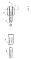
- FIG. 2 depicts a system for optically tracking blade position in an exemplary embodiment. Shown in FIG. 2 is a rotor blade spindle 30 mounted to an elastomeric bearing 32. A pivot center of the elastomeric bearing 32 is shown by axis A. A light source 34 is mounted to the blade spindle 30. Other mounting or positioning arrangements may be used so that light source 34 moves with movement of rotor blade 24 coupled to spindle 30. It is understood that light source 34 may be mounted to components other than spindle 30. Light source 34 may be any known type of light source, such as a laser diode. The term "light" is used herein to refer to any frequency so that visible and non-visible wavelengths may be generated by light source 34.
- a position detector 36 receives light from light source 34 and generates position signals indicative of a location of a light beam from light source 34 relative to reference axes of the position detector 36. Position detector 36 is described in further detail herein with reference to FIGs. 3 and 4 .
- a processor 38 receives output signals from the position detector 36 and computes one or more of lead-lag, flap and pitch of rotor blade 24 coupled to blade spindle 30. Processor 38 may be implemented using a general-purpose microprocessor executing a computer program to perform the operations described herein. Processor 38 may be implemented using hardware (e.g., ASIC, FPGA) and/or a combination of hardware and software.
- FIG. 3 depicts a system for optically tracking blade position using dual light beams in an exemplary embodiment.
- two lights sources 42 and 44 are mounted to blade spindle 30.
- Light sources 42 and 44 may be laser diodes separated by a small angle, with each laser diode directed at position detector 36.
- Position detector 36 is a two-dimensional position sensitive detector (2D PSD) that receives a light beam and outputs a voltage (Vx and Vy) proportional to x and y coordinates of the beam spot on the position detector 36.
- Position detector 36 may be mounted on the rotor hub.
- the light sources 42 and 44 are switched on and off, alternately, so that the instantaneous voltage outputs (Vx and Vy) of the position detector 36 represent the x and y coordinates along the x and y axes of the spot being currently illuminated.
- An alternating switch 50 is used to alternately provide power from power source 52 to the light sources 42 and 44. In this manner, only one of light source 42 and 44 produces a light beam at a time.
- the switch 50 may be controlled by processor 38, so that the processor 38 can synchronize the output signals from the position detector 36 with one of the light beams generated by light sources 42 and 44.
- processor 38 determines lead-lag, flap and pitch of rotor blade 24 mounted to spindle 30.
- the three angular motions of the blade spindle 30 can be calculated from the measured voltage outputs from the position detector 36 as shown below.
- Pitch ⁇ a ⁇ tan y b - y a / x b - x a ⁇ c 3 ⁇ V ya - V yb / V xa - V xb
- the notations a and b represent the two light sources 42 and 44, respectively.
- the value L is the distance from the position detector 36 to the pivot axis of the blade spindle 30.
- Coefficients c 1 , c 2 and c 3 are used to approximate the lead-lag, flap and pitch, respectively.
- the angular motions of flap and lead-lag are linearly determined by the average x and y coordinates of the two laser spots, respectively.
- the pitch motion is calculated based on the difference of two sets of the coordinates.
- the embodiment of FIG. 3 provides a direct measurement (each motion is proportional to the voltages) without need for computational conversion.
- the measurements of the three angular motions are also immune to the shift of the elastomeric bearing pivot center due to various centrifugal loading (e.g., x and y coordinates change with shift in distance L).
- two light beams are produced by alternately powering a first light source 42 and a second light source 44. It is understood that other techniques may be employed to generate the two light beams.
- both light sources 42 and 44 are constantly powered, and a shutter is alternately positioned to block one of the two light sources.
- the shutter may be controlled by processor 38, so that the processor 38 can synchronize the output signals from the position detector 36 with one of the light beams generated by light sources 42 and 44.
- a single light source is used and a positionable optical element (e.g., prism, lens system) is used to generate two light beams having the desired angular relationship.
- the optical element may be controlled by processor 38, so that the processor 38 can synchronize the output signals from the position detector 36 with one of the light beams generated by the optical element.
- FIG. 4 depicts a system for optically tracking blade position using a polarized light beam in an exemplary embodiment.
- a single light source 60 e.g., a laser diode
- Light source 60 outputs a collimated, polarized light beam.
- Position detector 62 is a two-dimensional position sensitive detector (2D PSD) that receives a light beam and outputs a voltage (Vx and Vy) proportional to x and y coordinates along the x and y axes of the beam spot on the detector 62.
- Position detector 62 also generates an intensity output V IO that is proportional to an intensity of the light beam on the position detector 62.
- Position detector 36 may be mounted on the rotor hub.
- a polarizing filter 64 is positioned in front of the position detector 60.
- the x and y coordinates from position detector 62 provide for computation of lead-lag and flap.
- the use of a polarized light beam and polarizing filter 64 make it possible to determine pitch.
- position detector 62 with polarizer filter 64 receives a polarized light beam
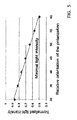
- the intensity of the light beam impinging position detector 62 is modulated by the relative orientation of the light source polarization direction and the polarizer filter polarization direction. This is represented in the intensity output V IO .
- the intensity of the polarized light passing through the polarizing filter 64 varies between zero and maximum as the light source 60 rotates with respect to the polarizer filter 64 from 90 degrees to 0 degrees.
- the position detector 62 intensity output is representative of the pitch angle (rotation about z axis) of blade 24.
- the three angular motions of the blade spindle 30 can be calculated from the measured voltage outputs from the position detector 62 as shown below.
- the value L is the distance from the position detector 62 to the pivot axis of the blade spindle 30.
- Coefficients c 1 , c 2 and c 3 are used to approximate the lead-lag, flap and pitch, respectively.
- FIG. 4 provides a direct measurement (each motion is proportional to the voltage) without need for computational conversion.
- the measurement of the three angular motions is also immune to the shift of the elastomeric bearing pivot center due various centrifugal loading (e.g., x and y coordinates change with shift in distance L).
- Embodiments provide three degrees of angular motion measurement simultaneously using one sensor. This provides for dynamic and static measurements with the same level of accuracy. The measurements are immune to shifts of the elastomeric bearing pivot center due aerodynamic and/or centrifugal loading. Direct measurements of angular motions are provided with minimal computation requirements.
Landscapes
- Engineering & Computer Science (AREA)
- Physics & Mathematics (AREA)
- General Physics & Mathematics (AREA)
- Electromagnetism (AREA)
- Mechanical Engineering (AREA)
- Aviation & Aerospace Engineering (AREA)
- Computer Networks & Wireless Communication (AREA)
- Radar, Positioning & Navigation (AREA)
- Remote Sensing (AREA)
- Length Measuring Devices By Optical Means (AREA)
Abstract
Description
- The subject matter disclosed herein relates generally to rotary wing aircraft, and in particular to optically tracking blades of a rotary wing aircraft.
- In the field of rotary wing aircraft, it is desirable to track blade motion. Rotating blades of a helicopter main rotor undergo an extremely complex motion trajectory with severe load conditions in a harsh environment. The on-board measurement of such rigid body motion at the root of the blade constitutes a major challenge for the helicopter industry. This measurement is particularly difficult for blades mounted to an elastomeric hinge-less bearing where the three angular motions (flap, pitch and lead-lag) are highly coupled and the elastomeric bearing pivot center shifts along the blade span due to centrifugal acceleration that varies with aerodynamic load and flight regimes. Existing methods to determine the blade motion in real time and in a non-contact fashion include holographic, Morie and laser Doppler vibrometer techniques. These non-contact optical measurement methods are only able to track one degree of freedom of motion at a time and may often fail to measure both statically and dynamically. They may also be very complex, bulky and unreliable in the main rotor environment and only appropriate for the laboratory environments and wind tunnel tests. Other methods of integrating acceleration from accelerometers or gyroscopes usually require added sensors or prior knowledge of the motion characteristics to remove drift due to integration and may be incapable of measuring static and low frequency motion of the main rotor blade.
- One embodiment includes an optical blade tracking system for a rotary wing aircraft, the system includinga light source generating at least one light beam, the light source coupled to a rotor blade of the rotary wing aircraft, wherein movement of the rotor blade is imparted to the light source; a two-dimensional position detector generating signals indicative of a position of the light beam along a first axis and a position of the light beam along a second axis and generating a signal indicative of an angular position of the light beam about a third axis; a processor receiving the signals, the processor determining at least one of lead-lag, flap and pitch of the rotor blade in response to the signals; and a polarizer filter positioned between the light source and the two dimensional position detector, the polarizer filter modulating intensity of the light beam onto the two dimensional position detector.
- Particular embodiments may include any of the following optional features, alone or in combination:
- The light beam may be polarized.
- The two-dimensional position detector may generate an intensity signal indicative of an intensity of the light beam on the two-dimensional position detector.
- The intensity signal may be indicative of an angular orientation between a light source polarization direction and a polarizer filter polarization direction.
- The processor may determine lead-lag of the rotor blade as:

- The processor may determine flap of the rotor blade as:

- The processor may determine pitch of the rotor blade as:

- Another embodiment is an optical blade tracking system for a rotary wing aircraft, the system including a light source generating at least one light beam, the light source coupled to a rotor blade of the rotary wing aircraft, wherein movement of the rotor blade is imparted to the light source; a two dimensional position detector generating signals indicative of a position of the light beam along a first axis and a position of the light beam along a second axis; and a processor receiving the signals, the processor determining at least one of lead-lag, flap and pitch of the rotor blade in response to the signals; wherein the at least one light beam comprises a first light beam and a second light beam generated at different times, the two dimensional position detector generated signals comprising a first signal indicative of a position of the first light beam along the first axis, a second signal indicative of a position of the first light beam along the second axis, a third signal indicative of a position of the second light beam along the first axis, and a fourth signal indicative of a position of the second light beam along the second axis.
- Particular embodiments may include any of the following optional features, alone or in combination:
- The light source may comprise a first light source generating the first light beam and a second light source generating the second light beam.
- The optical blade tracking system further may comprise a switch to alternately provide power the first light source and the second light source.
- The optical blade tracking further may comprise a shutter to alternately block an output of the first light source and the second light source.
- The optical blade tracking further may comprise a positionable optical element receiving the light beam and alternately generating the first light beam and the second light beam.
- The processor may determine lead-lag of the rotor blade as:

- The processor may determine flap of the rotor blade as:

- The processor may determine pitch of the rotor blade as:

- Another embodiment is a method for optical blade tracking for a rotary wing aircraft, the method including generating a first light beam and a second light beam at different times, a position of the first light beam and a position of the second light beam being responsive to movement of a rotor blade of the rotary wing aircraft; determining a position of the first light beam along a first axis, a position of the first light beam along a second axis, a position of the second light beam along the first axis, and a position of the second light beam along the second axis; determining at least one of lead-lag, flap and pitch of the rotor blade in response to the position of the first light beam along the first axis, the position of the first light beam along the second axis, the position of the second light beam along the first axis, and the position of the second light beam along the second axis.
- Particular embodiments may include any of the following optional features, alone or in combination:
- Determining pitch of the rotor blade may include dividing (i) a difference between the position of the first light beam along the second axis and the position of the second light beam along the second axis by (ii) a difference between the position of the first light beam along the first axis and the position of the second light beam along the first axis.
- Another embodiment is a method for optical blade tracking for a rotary wing aircraft, the method including generating a polarized light beam, a position of the polarized light beam being responsive to movement of a rotor blade of the rotary wing aircraft; determining a position of the polarized light beam along a first axis and a position of the polarized light beam along a second axis; determining a direction of polarization of the polarized light beam; determining at least one of lead-lag, flap and pitch of the rotor blade in response to the position of the polarized light beam along the first axis, the position of the polarized light beam along the second axis, and the direction of polarization of the polarized light beam.
- Particular embodiments may include any of the following optional features, alone or in combination:
- Determining pitch of the rotor blade may include determining an angle between the direction of polarization of the polarized light beam and a predetermined direction of polarization.
- Other aspects, features, and techniques of the invention will become more apparent from the following description taken in conjunction with the drawings.
- Referring now to the drawings wherein like elements are numbered alike in the several FIGURES, in which:
-
FIG. 1 depicts a rotary wing aircraft in an exemplary embodiment; -
FIG. 2 depicts a system for optically tracking blade position in an exemplary embodiment; -
FIG. 3 depicts a system for optically tracking blade position using dual light beams in an exemplary embodiment; -
FIG. 4 depicts a system for optically tracking blade position using a polarized light beam in an exemplary embodiment; and -
FIG. 5 is a plot of light intensity versus relative polarization in an exemplary embodiment. -
FIG. 1 illustrates arotary wing aircraft 10 having amain rotor assembly 12 in an exemplary embodiment. Theaircraft 10 includes anairframe 14 having an extendingtail 16 which mounts atail rotor system 18, such as an anti-torque system, a translational thrust system, a pusher propeller, a rotor propulsion system, and the like. Themain rotor assembly 12 is driven about an axis of rotation R through a main gearbox (illustrated schematically at 20) by one ormore engines 22. Themain rotor assembly 12 includes a plurality ofrotor blades 24 mounted to arotor hub 26. Although a particular rotary wing aircraft configuration is illustrated, other configurations and/or machines, such as high speed compound rotary wing aircraft with supplemental translational thrust systems, dual contra-rotating aircraft, coaxial rotor system aircraft, turbo-props, tilt-rotors and tilt-wing aircraft, will also benefit from embodiments of the invention. -
FIG. 2 depicts a system for optically tracking blade position in an exemplary embodiment. Shown inFIG. 2 is arotor blade spindle 30 mounted to anelastomeric bearing 32. A pivot center of theelastomeric bearing 32 is shown by axis A. Alight source 34 is mounted to theblade spindle 30. Other mounting or positioning arrangements may be used so thatlight source 34 moves with movement ofrotor blade 24 coupled tospindle 30. It is understood thatlight source 34 may be mounted to components other thanspindle 30.Light source 34 may be any known type of light source, such as a laser diode. The term "light" is used herein to refer to any frequency so that visible and non-visible wavelengths may be generated bylight source 34. - A
position detector 36 receives light fromlight source 34 and generates position signals indicative of a location of a light beam fromlight source 34 relative to reference axes of theposition detector 36.Position detector 36 is described in further detail herein with reference toFIGs. 3 and4 . Aprocessor 38 receives output signals from theposition detector 36 and computes one or more of lead-lag, flap and pitch ofrotor blade 24 coupled toblade spindle 30.Processor 38 may be implemented using a general-purpose microprocessor executing a computer program to perform the operations described herein.Processor 38 may be implemented using hardware (e.g., ASIC, FPGA) and/or a combination of hardware and software. -
FIG. 3 depicts a system for optically tracking blade position using dual light beams in an exemplary embodiment. In the embodiment ofFIG. 3 , twolights sources blade spindle 30.Light sources position detector 36. -
Position detector 36 is a two-dimensional position sensitive detector (2D PSD) that receives a light beam and outputs a voltage (Vx and Vy) proportional to x and y coordinates of the beam spot on theposition detector 36.Position detector 36 may be mounted on the rotor hub. - As the
position detector 36 only generates x and y coordinates for a single point, thelight sources position detector 36 represent the x and y coordinates along the x and y axes of the spot being currently illuminated. Analternating switch 50 is used to alternately provide power frompower source 52 to thelight sources light source switch 50 may be controlled byprocessor 38, so that theprocessor 38 can synchronize the output signals from theposition detector 36 with one of the light beams generated bylight sources - From the output signals of the
position detector 36,processor 38 determines lead-lag, flap and pitch ofrotor blade 24 mounted tospindle 30. The three angular motions of theblade spindle 30 can be calculated from the measured voltage outputs from theposition detector 36 as shown below.


- In the above equations, the notations a and b represent the two
light sources position detector 36 to the pivot axis of theblade spindle 30. Coefficients c1, c2 and c3 are used to approximate the lead-lag, flap and pitch, respectively. - The angular motions of flap and lead-lag are linearly determined by the average x and y coordinates of the two laser spots, respectively. The pitch motion is calculated based on the difference of two sets of the coordinates. The embodiment of
FIG. 3 provides a direct measurement (each motion is proportional to the voltages) without need for computational conversion. The measurements of the three angular motions are also immune to the shift of the elastomeric bearing pivot center due to various centrifugal loading (e.g., x and y coordinates change with shift in distance L). - In the embodiment of
FIG. 3 , two light beams are produced by alternately powering afirst light source 42 and a secondlight source 44. It is understood that other techniques may be employed to generate the two light beams. For example, in an alternative embodiment bothlight sources processor 38, so that theprocessor 38 can synchronize the output signals from theposition detector 36 with one of the light beams generated bylight sources processor 38, so that theprocessor 38 can synchronize the output signals from theposition detector 36 with one of the light beams generated by the optical element. -
FIG. 4 depicts a system for optically tracking blade position using a polarized light beam in an exemplary embodiment. As shown inFIG. 4 , a single light source 60 (e.g., a laser diode) is mounted toblade spindle 30.Light source 60 outputs a collimated, polarized light beam.Position detector 62 is a two-dimensional position sensitive detector (2D PSD) that receives a light beam and outputs a voltage (Vx and Vy) proportional to x and y coordinates along the x and y axes of the beam spot on thedetector 62.Position detector 62 also generates an intensity output VIO that is proportional to an intensity of the light beam on theposition detector 62.Position detector 36 may be mounted on the rotor hub. Apolarizing filter 64 is positioned in front of theposition detector 60. - The x and y coordinates from
position detector 62 provide for computation of lead-lag and flap. The use of a polarized light beam andpolarizing filter 64 make it possible to determine pitch. Whenposition detector 62 withpolarizer filter 64 receives a polarized light beam, the intensity of the light beamimpinging position detector 62 is modulated by the relative orientation of the light source polarization direction and the polarizer filter polarization direction. This is represented in the intensity output VIO. The intensity of the polarized light passing through thepolarizing filter 64 varies between zero and maximum as thelight source 60 rotates with respect to thepolarizer filter 64 from 90 degrees to 0 degrees.FIG. 5 illustrates light intensity at theposition detector 62 versus relative angle between the polarization direction of thelight source 60 and polarizationdirection polarization filter 64. Therefore, theposition detector 62 intensity output is representative of the pitch angle (rotation about z axis) ofblade 24. - The three angular motions of the
blade spindle 30 can be calculated from the measured voltage outputs from theposition detector 62 as shown below.


- In the above equations, the value L is the distance from the
position detector 62 to the pivot axis of theblade spindle 30. Coefficients c1, c2 and c3 are used to approximate the lead-lag, flap and pitch, respectively. - The embodiment of
FIG. 4 provides a direct measurement (each motion is proportional to the voltage) without need for computational conversion. The measurement of the three angular motions is also immune to the shift of the elastomeric bearing pivot center due various centrifugal loading (e.g., x and y coordinates change with shift in distance L). - Embodiments provide three degrees of angular motion measurement simultaneously using one sensor. This provides for dynamic and static measurements with the same level of accuracy. The measurements are immune to shifts of the elastomeric bearing pivot center due aerodynamic and/or centrifugal loading. Direct measurements of angular motions are provided with minimal computation requirements.
- The terminology used herein is for the purpose of describing particular embodiments only and is not intended to be limiting of the invention. While the description of the present invention has been presented for purposes of illustration and description, it is not intended to be exhaustive or limited to the invention in the form disclosed. Many modifications, variations, alterations, substitutions, or equivalent arrangement not hereto described will be apparent to those of ordinary skill in the art without departing from the scope and spirit of the invention. Additionally, while various embodiments of the invention have been described, it is to be understood that aspects of the invention may include only some of the described embodiments. Accordingly, the invention is not to be seen as limited by the foregoing description, but is only limited by the scope of the appended claims.
- This invention was made with Government support under Agreement No. W911 W6-10-2-0006 COST-A. The Government has certain rights in the invention.
Claims (15)
- An optical blade tracking system for a rotary wing aircraft (10), the system comprising:a light source (34; 60) generating at least one light beam, the light source (34) coupled to a rotor blade (24) of the rotary wing aircraft (10), wherein movement of the rotor blade is imparted to the light source (34);a two-dimensional position detector (62) generating signals indicative of a position of the light beam along a first axis and a position of the light beam along a second axis and generating a signal indicative of an angular position of the light beam about a third axis;a processor (38) receiving the signals, the processor (38) determining at least one of lead-lag, flap and pitch of the rotor blade in response to the signals; anda polarizer filter (64) positioned between the light source and the two dimensional position detector, the polarizer filter (64) modulating intensity of the light beam onto the two-dimensional position detector (62).
- The optical blade tracking system of claim 1, wherein:the light beam is polarized; and/or wherein:the two-dimensional position detector (62) generates an intensity signal indicative of an intensity of the light beam on the two-dimensional position detector (62); and/or wherein:the intensity signal is indicative of an angular orientation between a light source polarization direction and a polarizer filter polarization direction.
- The optical blade tracking system of claim 1 or 2, wherein:the processor (38) determines lead-lag of the rotor blade as:

wherein Vx is the signal indicative of the position of the light beam along the first axis, and c1 is a coefficient. - The optical blade tracking system of any of claims 1 to 3, wherein:the processor (38) determines flap of the rotor blade as:

wherein Vy is the signal indicative of the position of the light beam along the second axis and c2 is a coefficient. - The optical blade tracking system of any of claims 1 to 4, wherein:the processor determines pitch of the rotor blade as:

wherein VIO is the intensity signal and c3 is a coefficient. - An optical blade tracking system for a rotary wing aircraft (10), the system comprising:a light source (34) generating at least one light beam, the light source (34) coupled to a rotor blade (24) of the rotary wing aircraft (10), wherein movement of the rotor blade (24) is imparted to the light source (34);a two-dimensional position detector (36) generating signals indicative of a position of the light beam along a first axis and a position of the light beam along a second axis; anda processor (38) receiving the signals, the processor (38) determining at least one of lead-lag, flap and pitch of the rotor blade (24) in response to the signals;wherein the at least one light beam comprises a first light beam and a second light beam generated at different times, the two-dimensional position detector generated signals comprising a first signal indicative of a position of the first light beam along the first axis, a second signal indicative of a position of the first light beam along the second axis, a third signal indicative of a position of the second light beam along the first axis, and a fourth signal indicative of a position of the second light beam along the second axis.
- The optical blade tracking system of claim 6, wherein:the light source (34) comprises a first light source (42) generating the first light beam and a second light source (44) generating the second light beam; and/or further comprising:a switch (50) to alternately provide power the first light source and the second light source (44); and/or further comprising:a shutter to alternately block an output of the first light source and the second light source.
- The optical blade tracking system of claim 6 or 7, further comprising:a positionable optical element receiving the light beam and alternately generating the first light beam and the second light beam.
- The optical blade tracking system of any of claims 6 to 8, wherein:the processor (38) determines lead-lag of the rotor blade (24) as:

wherein Vxa is the first signal indicative of the position of the first light beam along the first axis, Vxb is the third signal third signal indicative of the position of the second light beam along the first axis and c1 is a coefficient. - The optical blade tracking system of any of claims 6 to 9, wherein:the processor determines flap of the rotor blade as:

wherein Vya is the second signal indicative of the position of the first light beam along the second axis, Vyb is the fourth signal indicative of the position of the second light beam along the second axis and c2 is a coefficient. - The optical blade tracking system of any of claims 6 to 10, wherein:the processor (38) determines pitch of the rotor blade as:

wherein Vya is the second signal indicative of the position of the first light beam along the second axis, Vyb is the fourth signal indicative of the position of the second light beam along the second axis, Vxa is the first signal indicative of the position of the first light beam along the first axis, Vxb is the third signal third signal indicative of the position of the second light beam along the first axis and c3 is a coefficient. - A method for optical blade tracking for a rotary wing aircraft, the method comprising:generating a first light beam and a second light beam at different times, a position of the first light beam and a position of the second light beam being responsive to movement of a rotor blade of the rotary wing aircraft;determining a position of the first light beam along a first axis, a position of the first light beam along a second axis, a position of the second light beam along the first axis, and a position of the second light beam along the second axis;determining at least one of lead-lag, flap and pitch of the rotor blade in response to the position of the first light beam along the first axis, the position of the first light beam along the second axis, the position of the second light beam along the first axis, and the position of the second light beam along the second axis.
- The method of claim 12 wherein:determining pitch of the rotor blade includes dividing (i) a difference between the position of the first light beam along the second axis and the position of the second light beam along the second axis by (ii) a difference between the position of the first light beam along the first axis and the position of the second light beam along the first axis.
- A method for optical blade tracking for a rotary wing aircraft, the method comprising:generating a polarized light beam, a position of the polarized light beam being responsive to movement of a rotor blade of the rotary wing aircraft;determining a position of the polarized light beam along a first axis and a position of the polarized light beam along a second axis;determining a direction of polarization of the polarized light beam;determining at least one of lead-lag, flap and pitch of the rotor blade in response to the position of the polarized light beam along the first axis, the position of the polarized light beam along the second axis, and the direction of polarization of the polarized light beam.
- The method of claim 14 wherein:determining pitch of the rotor blade includes determining an angle between the direction of polarization of the polarized light beam and a predetermined direction of polarization.
Applications Claiming Priority (1)
| Application Number | Priority Date | Filing Date | Title |
|---|---|---|---|
| US13/766,126 US9470793B2 (en) | 2013-02-13 | 2013-02-13 | Optical tracking of rotor blade motion |
Publications (2)
| Publication Number | Publication Date |
|---|---|
| EP2767468A1 true EP2767468A1 (en) | 2014-08-20 |
| EP2767468B1 EP2767468B1 (en) | 2016-10-05 |
Family
ID=49918391
Family Applications (1)
| Application Number | Title | Priority Date | Filing Date |
|---|---|---|---|
| EP13197490.9A Active EP2767468B1 (en) | 2013-02-13 | 2013-12-16 | Optical tracking of rotor blade motion |
Country Status (2)
| Country | Link |
|---|---|
| US (1) | US9470793B2 (en) |
| EP (1) | EP2767468B1 (en) |
Cited By (2)
| Publication number | Priority date | Publication date | Assignee | Title |
|---|---|---|---|---|
| CN105701802A (en) * | 2014-11-27 | 2016-06-22 | 空客直升机 | Device for measuring the angular positions of a rotorcraft blade element relative to a rotor hub, an associated rotor, and a corresponding measurement method |
| CN108489428A (en) * | 2018-04-11 | 2018-09-04 | 徐工集团工程机械有限公司 | Piston cylinder axiality detection device and method |
Families Citing this family (7)
| Publication number | Priority date | Publication date | Assignee | Title |
|---|---|---|---|---|
| US20180148165A1 (en) * | 2015-05-11 | 2018-05-31 | Sikorsky Aircraft Corporation | Rotor state feedback system |
| US10338202B2 (en) * | 2016-01-28 | 2019-07-02 | General Electric Company | System and method for improving LIDAR sensor signal availability on a wind turbine |
| JP6058229B1 (en) * | 2016-03-01 | 2017-01-11 | 三菱電機株式会社 | Windmill start assist device |
| US12326725B2 (en) | 2017-02-27 | 2025-06-10 | Northwestern University | Sensing and communication system for rotorcraft |
| US11141863B2 (en) * | 2018-10-11 | 2021-10-12 | Pixart Imaging Inc. | Cleaning robot capable of detecting 2D depth information and operating method thereof |
| CN110844110B (en) * | 2019-10-11 | 2022-09-30 | 中国直升机设计研究所 | Method for determining phase of blade motion parameter |
| US11420772B2 (en) * | 2019-12-17 | 2022-08-23 | Pratt & Whitney Canada Corp. | System and method for determining an axial position of a feedback device |
Citations (5)
| Publication number | Priority date | Publication date | Assignee | Title |
|---|---|---|---|---|
| US5137353A (en) * | 1991-10-10 | 1992-08-11 | The United States Of America As Represented By The Administrator Of The National Aeronautics And Space Administration | Angular displacement measuring device |
| JPH10281750A (en) * | 1997-04-07 | 1998-10-23 | Kawasaki Heavy Ind Ltd | Displacement measuring equipment for blade of rotor |
| JP2010149602A (en) * | 2008-12-24 | 2010-07-08 | Kawasaki Heavy Ind Ltd | Method and device for detecting rotor blade displacement of rotor craft |
| US20100253569A1 (en) * | 2009-04-07 | 2010-10-07 | Henrik Stiesdal | Method and arrangement to measure the deflection of a wind turbine blade |
| US20110243730A1 (en) * | 2010-12-14 | 2011-10-06 | Eric David Eggleston | Systems and methods for determining deflection of a wind turbine shaft |
Family Cites Families (5)
| Publication number | Priority date | Publication date | Assignee | Title |
|---|---|---|---|---|
| GB2116804B (en) * | 1982-03-16 | 1986-03-26 | Micro Control Tech Ltd | Detecting irregularities in rotating masses |
| US4583862A (en) * | 1983-12-19 | 1986-04-22 | United Technologies Corporation | Optical position and orientation sensing systems |
| GB2213931B (en) | 1988-01-13 | 1992-04-15 | Stewart Hughes Ltd | Improvements in and relating to rotor blade tracking devices |
| JPH10145668A (en) * | 1996-11-14 | 1998-05-29 | Nikon Corp | Polarizing filter control mechanism |
| DE112009005524B3 (en) | 2008-11-17 | 2018-01-25 | Faro Technologies, Inc. | Apparatus and method for measuring six degrees of freedom |
-
2013
- 2013-02-13 US US13/766,126 patent/US9470793B2/en active Active
- 2013-12-16 EP EP13197490.9A patent/EP2767468B1/en active Active
Patent Citations (5)
| Publication number | Priority date | Publication date | Assignee | Title |
|---|---|---|---|---|
| US5137353A (en) * | 1991-10-10 | 1992-08-11 | The United States Of America As Represented By The Administrator Of The National Aeronautics And Space Administration | Angular displacement measuring device |
| JPH10281750A (en) * | 1997-04-07 | 1998-10-23 | Kawasaki Heavy Ind Ltd | Displacement measuring equipment for blade of rotor |
| JP2010149602A (en) * | 2008-12-24 | 2010-07-08 | Kawasaki Heavy Ind Ltd | Method and device for detecting rotor blade displacement of rotor craft |
| US20100253569A1 (en) * | 2009-04-07 | 2010-10-07 | Henrik Stiesdal | Method and arrangement to measure the deflection of a wind turbine blade |
| US20110243730A1 (en) * | 2010-12-14 | 2011-10-06 | Eric David Eggleston | Systems and methods for determining deflection of a wind turbine shaft |
Cited By (4)
| Publication number | Priority date | Publication date | Assignee | Title |
|---|---|---|---|---|
| CN105701802A (en) * | 2014-11-27 | 2016-06-22 | 空客直升机 | Device for measuring the angular positions of a rotorcraft blade element relative to a rotor hub, an associated rotor, and a corresponding measurement method |
| CN105701802B (en) * | 2014-11-27 | 2018-08-10 | 空客直升机 | Measure equipment, method and the associated rotor of gyroplane blade element angle position |
| CN108489428A (en) * | 2018-04-11 | 2018-09-04 | 徐工集团工程机械有限公司 | Piston cylinder axiality detection device and method |
| CN108489428B (en) * | 2018-04-11 | 2019-12-27 | 徐工集团工程机械有限公司 | Device and method for detecting coaxiality of piston cylinder |
Also Published As
| Publication number | Publication date |
|---|---|
| US9470793B2 (en) | 2016-10-18 |
| US20140226153A1 (en) | 2014-08-14 |
| EP2767468B1 (en) | 2016-10-05 |
Similar Documents
| Publication | Publication Date | Title |
|---|---|---|
| EP2767468B1 (en) | Optical tracking of rotor blade motion | |
| US9758258B2 (en) | Rotary wing aircraft blade tracking | |
| Pilarska et al. | The potential of light laser scanners developed for unmanned aerial vehicles-the review and accuracy | |
| US9857198B2 (en) | Apparatus and method for inertial sensor calibration | |
| US20060227318A1 (en) | Combined laser altimeter and ground velocity measurement apparatus | |
| Radkowski et al. | Analysis of vibration of rotors in unmanned aircraft | |
| US10752341B2 (en) | Tip clearance harmonic estimation | |
| US11162812B2 (en) | Optimal path planning with optical air velocity sensing | |
| KR20160038765A (en) | Aero-wave instrument system to measure optical wavefront disturbances in airflow about airborne systems | |
| EP3838749B1 (en) | System and method for dynamically measuring blade position during flight of a rotorcraft | |
| US11851193B2 (en) | Blended optical and vane synthetic air data architecture | |
| JP2911551B2 (en) | Apparatus for obtaining on a vehicle a signal representing the relative speed of the vehicle relative to the surrounding fluid | |
| Olson et al. | Blade deflection measurements of a full-scale UH-60A rotor system | |
| KR20140034716A (en) | System and method for measurement of angular orientation of aerospace platforms | |
| EP2975427B1 (en) | Active blade tracker and related systems and methods | |
| US11041876B2 (en) | System for measuring the distance of an obstacle using optical flow | |
| JP2010149602A (en) | Method and device for detecting rotor blade displacement of rotor craft | |
| KR102702574B1 (en) | Inertial sensor | |
| CN112415535B (en) | Navigation system and navigation method | |
| RU2566379C1 (en) | Method for determining value of atmospheric refraction under conditions of space flight | |
| RU2386107C1 (en) | Independent method of determining initial orientation of instrument coordinate system of gimballess inertial unit of controlled object relative base coordinate system | |
| RU2347193C1 (en) | Methods of determination of attack angles and slide at flight trials of supersonic flying machine | |
| RU168214U1 (en) | Strap-on integrated inertial heading vertical | |
| US6938472B2 (en) | Static pressure calculation from dynamic pressure for rotary air-data system and methodology therefor | |
| EP3798642B1 (en) | Coriolis vibratory accelerometer system |
Legal Events
| Date | Code | Title | Description |
|---|---|---|---|
| PUAI | Public reference made under article 153(3) epc to a published international application that has entered the european phase |
Free format text: ORIGINAL CODE: 0009012 |
|
| 17P | Request for examination filed |
Effective date: 20131216 |
|
| AK | Designated contracting states |
Kind code of ref document: A1 Designated state(s): AL AT BE BG CH CY CZ DE DK EE ES FI FR GB GR HR HU IE IS IT LI LT LU LV MC MK MT NL NO PL PT RO RS SE SI SK SM TR |
|
| AX | Request for extension of the european patent |
Extension state: BA ME |
|
| R17P | Request for examination filed (corrected) |
Effective date: 20140902 |
|
| RBV | Designated contracting states (corrected) |
Designated state(s): AL AT BE BG CH CY CZ DE DK EE ES FI FR GB GR HR HU IE IS IT LI LT LU LV MC MK MT NL NO PL PT RO RS SE SI SK SM TR |
|
| GRAP | Despatch of communication of intention to grant a patent |
Free format text: ORIGINAL CODE: EPIDOSNIGR1 |
|
| INTG | Intention to grant announced |
Effective date: 20160415 |
|
| RIN1 | Information on inventor provided before grant (corrected) |
Inventor name: KIM, SEUNG BUM Inventor name: MAJKO, DAVID JAMES Inventor name: SUN, FANPING Inventor name: CHAUDHRY, ZAFFIR, A. Inventor name: FANG, AUSTIN Inventor name: WASILEWSKI, MATTHEW JAMES Inventor name: GUZMAN, ALONSO Inventor name: JAMES, CURTIS S. Inventor name: LEX, ROBERT MARK Inventor name: SAMUELS, HARVEY A. |
|
| RIN1 | Information on inventor provided before grant (corrected) |
Inventor name: LEX, ROBERT MARK Inventor name: KIM, SEUNG BUM Inventor name: FANG, AUSTIN Inventor name: SAMUELS, HARVEY A. Inventor name: JAMES, CURTIS S. Inventor name: SUN, FANPING Inventor name: GUZMAN, ALONSO Inventor name: MAJKO, DAVID JAMES Inventor name: CHAUDHRY, ZAFFIR, A. Inventor name: WASILEWSKI, MATTHEW JAMES |
|
| GRAS | Grant fee paid |
Free format text: ORIGINAL CODE: EPIDOSNIGR3 |
|
| GRAA | (expected) grant |
Free format text: ORIGINAL CODE: 0009210 |
|
| AK | Designated contracting states |
Kind code of ref document: B1 Designated state(s): AL AT BE BG CH CY CZ DE DK EE ES FI FR GB GR HR HU IE IS IT LI LT LU LV MC MK MT NL NO PL PT RO RS SE SI SK SM TR |
|
| REG | Reference to a national code |
Ref country code: GB Ref legal event code: FG4D |
|
| REG | Reference to a national code |
Ref country code: CH Ref legal event code: EP |
|
| REG | Reference to a national code |
Ref country code: AT Ref legal event code: REF Ref document number: 834379 Country of ref document: AT Kind code of ref document: T Effective date: 20161015 |
|
| REG | Reference to a national code |
Ref country code: IE Ref legal event code: FG4D |
|
| REG | Reference to a national code |
Ref country code: DE Ref legal event code: R096 Ref document number: 602013012371 Country of ref document: DE |
|
| REG | Reference to a national code |
Ref country code: FR Ref legal event code: PLFP Year of fee payment: 4 |
|
| REG | Reference to a national code |
Ref country code: NL Ref legal event code: MP Effective date: 20161005 |
|
| REG | Reference to a national code |
Ref country code: LT Ref legal event code: MG4D |
|
| PG25 | Lapsed in a contracting state [announced via postgrant information from national office to epo] |
Ref country code: LV Free format text: LAPSE BECAUSE OF FAILURE TO SUBMIT A TRANSLATION OF THE DESCRIPTION OR TO PAY THE FEE WITHIN THE PRESCRIBED TIME-LIMIT Effective date: 20161005 |
|
| REG | Reference to a national code |
Ref country code: AT Ref legal event code: MK05 Ref document number: 834379 Country of ref document: AT Kind code of ref document: T Effective date: 20161005 |
|
| PG25 | Lapsed in a contracting state [announced via postgrant information from national office to epo] |
Ref country code: SE Free format text: LAPSE BECAUSE OF FAILURE TO SUBMIT A TRANSLATION OF THE DESCRIPTION OR TO PAY THE FEE WITHIN THE PRESCRIBED TIME-LIMIT Effective date: 20161005 Ref country code: LT Free format text: LAPSE BECAUSE OF FAILURE TO SUBMIT A TRANSLATION OF THE DESCRIPTION OR TO PAY THE FEE WITHIN THE PRESCRIBED TIME-LIMIT Effective date: 20161005 Ref country code: NO Free format text: LAPSE BECAUSE OF FAILURE TO SUBMIT A TRANSLATION OF THE DESCRIPTION OR TO PAY THE FEE WITHIN THE PRESCRIBED TIME-LIMIT Effective date: 20170105 Ref country code: GR Free format text: LAPSE BECAUSE OF FAILURE TO SUBMIT A TRANSLATION OF THE DESCRIPTION OR TO PAY THE FEE WITHIN THE PRESCRIBED TIME-LIMIT Effective date: 20170106 |
|
| PG25 | Lapsed in a contracting state [announced via postgrant information from national office to epo] |
Ref country code: NL Free format text: LAPSE BECAUSE OF FAILURE TO SUBMIT A TRANSLATION OF THE DESCRIPTION OR TO PAY THE FEE WITHIN THE PRESCRIBED TIME-LIMIT Effective date: 20161005 Ref country code: HR Free format text: LAPSE BECAUSE OF FAILURE TO SUBMIT A TRANSLATION OF THE DESCRIPTION OR TO PAY THE FEE WITHIN THE PRESCRIBED TIME-LIMIT Effective date: 20161005 Ref country code: ES Free format text: LAPSE BECAUSE OF FAILURE TO SUBMIT A TRANSLATION OF THE DESCRIPTION OR TO PAY THE FEE WITHIN THE PRESCRIBED TIME-LIMIT Effective date: 20161005 Ref country code: FI Free format text: LAPSE BECAUSE OF FAILURE TO SUBMIT A TRANSLATION OF THE DESCRIPTION OR TO PAY THE FEE WITHIN THE PRESCRIBED TIME-LIMIT Effective date: 20161005 Ref country code: BE Free format text: LAPSE BECAUSE OF FAILURE TO SUBMIT A TRANSLATION OF THE DESCRIPTION OR TO PAY THE FEE WITHIN THE PRESCRIBED TIME-LIMIT Effective date: 20161005 Ref country code: PT Free format text: LAPSE BECAUSE OF FAILURE TO SUBMIT A TRANSLATION OF THE DESCRIPTION OR TO PAY THE FEE WITHIN THE PRESCRIBED TIME-LIMIT Effective date: 20170206 Ref country code: IS Free format text: LAPSE BECAUSE OF FAILURE TO SUBMIT A TRANSLATION OF THE DESCRIPTION OR TO PAY THE FEE WITHIN THE PRESCRIBED TIME-LIMIT Effective date: 20170205 Ref country code: PL Free format text: LAPSE BECAUSE OF FAILURE TO SUBMIT A TRANSLATION OF THE DESCRIPTION OR TO PAY THE FEE WITHIN THE PRESCRIBED TIME-LIMIT Effective date: 20161005 Ref country code: AT Free format text: LAPSE BECAUSE OF FAILURE TO SUBMIT A TRANSLATION OF THE DESCRIPTION OR TO PAY THE FEE WITHIN THE PRESCRIBED TIME-LIMIT Effective date: 20161005 Ref country code: RS Free format text: LAPSE BECAUSE OF FAILURE TO SUBMIT A TRANSLATION OF THE DESCRIPTION OR TO PAY THE FEE WITHIN THE PRESCRIBED TIME-LIMIT Effective date: 20161005 |
|
| REG | Reference to a national code |
Ref country code: DE Ref legal event code: R097 Ref document number: 602013012371 Country of ref document: DE |
|
| REG | Reference to a national code |
Ref country code: DE Ref legal event code: R082 Ref document number: 602013012371 Country of ref document: DE Representative=s name: SCHMITT-NILSON SCHRAUD WAIBEL WOHLFROM PATENTA, DE |
|
| PG25 | Lapsed in a contracting state [announced via postgrant information from national office to epo] |
Ref country code: RO Free format text: LAPSE BECAUSE OF FAILURE TO SUBMIT A TRANSLATION OF THE DESCRIPTION OR TO PAY THE FEE WITHIN THE PRESCRIBED TIME-LIMIT Effective date: 20161005 Ref country code: DK Free format text: LAPSE BECAUSE OF FAILURE TO SUBMIT A TRANSLATION OF THE DESCRIPTION OR TO PAY THE FEE WITHIN THE PRESCRIBED TIME-LIMIT Effective date: 20161005 Ref country code: SK Free format text: LAPSE BECAUSE OF FAILURE TO SUBMIT A TRANSLATION OF THE DESCRIPTION OR TO PAY THE FEE WITHIN THE PRESCRIBED TIME-LIMIT Effective date: 20161005 Ref country code: EE Free format text: LAPSE BECAUSE OF FAILURE TO SUBMIT A TRANSLATION OF THE DESCRIPTION OR TO PAY THE FEE WITHIN THE PRESCRIBED TIME-LIMIT Effective date: 20161005 Ref country code: CZ Free format text: LAPSE BECAUSE OF FAILURE TO SUBMIT A TRANSLATION OF THE DESCRIPTION OR TO PAY THE FEE WITHIN THE PRESCRIBED TIME-LIMIT Effective date: 20161005 |
|
| REG | Reference to a national code |
Ref country code: CH Ref legal event code: PL |
|
| PLBE | No opposition filed within time limit |
Free format text: ORIGINAL CODE: 0009261 |
|
| STAA | Information on the status of an ep patent application or granted ep patent |
Free format text: STATUS: NO OPPOSITION FILED WITHIN TIME LIMIT |
|
| PG25 | Lapsed in a contracting state [announced via postgrant information from national office to epo] |
Ref country code: BG Free format text: LAPSE BECAUSE OF FAILURE TO SUBMIT A TRANSLATION OF THE DESCRIPTION OR TO PAY THE FEE WITHIN THE PRESCRIBED TIME-LIMIT Effective date: 20170105 Ref country code: SM Free format text: LAPSE BECAUSE OF FAILURE TO SUBMIT A TRANSLATION OF THE DESCRIPTION OR TO PAY THE FEE WITHIN THE PRESCRIBED TIME-LIMIT Effective date: 20161005 |
|
| 26N | No opposition filed |
Effective date: 20170706 |
|
| PG25 | Lapsed in a contracting state [announced via postgrant information from national office to epo] |
Ref country code: MC Free format text: LAPSE BECAUSE OF FAILURE TO SUBMIT A TRANSLATION OF THE DESCRIPTION OR TO PAY THE FEE WITHIN THE PRESCRIBED TIME-LIMIT Effective date: 20161005 |
|
| REG | Reference to a national code |
Ref country code: IE Ref legal event code: MM4A |
|
| PG25 | Lapsed in a contracting state [announced via postgrant information from national office to epo] |
Ref country code: LU Free format text: LAPSE BECAUSE OF NON-PAYMENT OF DUE FEES Effective date: 20161216 Ref country code: CH Free format text: LAPSE BECAUSE OF NON-PAYMENT OF DUE FEES Effective date: 20161231 Ref country code: LI Free format text: LAPSE BECAUSE OF NON-PAYMENT OF DUE FEES Effective date: 20161231 |
|
| PG25 | Lapsed in a contracting state [announced via postgrant information from national office to epo] |
Ref country code: IE Free format text: LAPSE BECAUSE OF NON-PAYMENT OF DUE FEES Effective date: 20161216 Ref country code: SI Free format text: LAPSE BECAUSE OF FAILURE TO SUBMIT A TRANSLATION OF THE DESCRIPTION OR TO PAY THE FEE WITHIN THE PRESCRIBED TIME-LIMIT Effective date: 20161005 |
|
| REG | Reference to a national code |
Ref country code: FR Ref legal event code: PLFP Year of fee payment: 5 |
|
| PG25 | Lapsed in a contracting state [announced via postgrant information from national office to epo] |
Ref country code: HU Free format text: LAPSE BECAUSE OF FAILURE TO SUBMIT A TRANSLATION OF THE DESCRIPTION OR TO PAY THE FEE WITHIN THE PRESCRIBED TIME-LIMIT; INVALID AB INITIO Effective date: 20131216 |
|
| PG25 | Lapsed in a contracting state [announced via postgrant information from national office to epo] |
Ref country code: CY Free format text: LAPSE BECAUSE OF FAILURE TO SUBMIT A TRANSLATION OF THE DESCRIPTION OR TO PAY THE FEE WITHIN THE PRESCRIBED TIME-LIMIT Effective date: 20161005 Ref country code: MK Free format text: LAPSE BECAUSE OF FAILURE TO SUBMIT A TRANSLATION OF THE DESCRIPTION OR TO PAY THE FEE WITHIN THE PRESCRIBED TIME-LIMIT Effective date: 20161005 |
|
| PG25 | Lapsed in a contracting state [announced via postgrant information from national office to epo] |
Ref country code: MT Free format text: LAPSE BECAUSE OF NON-PAYMENT OF DUE FEES Effective date: 20161216 |
|
| PG25 | Lapsed in a contracting state [announced via postgrant information from national office to epo] |
Ref country code: TR Free format text: LAPSE BECAUSE OF FAILURE TO SUBMIT A TRANSLATION OF THE DESCRIPTION OR TO PAY THE FEE WITHIN THE PRESCRIBED TIME-LIMIT Effective date: 20161005 |
|
| PG25 | Lapsed in a contracting state [announced via postgrant information from national office to epo] |
Ref country code: AL Free format text: LAPSE BECAUSE OF FAILURE TO SUBMIT A TRANSLATION OF THE DESCRIPTION OR TO PAY THE FEE WITHIN THE PRESCRIBED TIME-LIMIT Effective date: 20161005 |
|
| P01 | Opt-out of the competence of the unified patent court (upc) registered |
Effective date: 20230523 |
|
| PGFP | Annual fee paid to national office [announced via postgrant information from national office to epo] |
Ref country code: GB Payment date: 20241227 Year of fee payment: 12 |
|
| PGFP | Annual fee paid to national office [announced via postgrant information from national office to epo] |
Ref country code: FR Payment date: 20241226 Year of fee payment: 12 |
|
| PGFP | Annual fee paid to national office [announced via postgrant information from national office to epo] |
Ref country code: IT Payment date: 20241218 Year of fee payment: 12 |
|
| PGFP | Annual fee paid to national office [announced via postgrant information from national office to epo] |
Ref country code: DE Payment date: 20241227 Year of fee payment: 12 |