EP2767429A1 - Charging port lock device - Google Patents
Charging port lock device Download PDFInfo
- Publication number
- EP2767429A1 EP2767429A1 EP12840364.9A EP12840364A EP2767429A1 EP 2767429 A1 EP2767429 A1 EP 2767429A1 EP 12840364 A EP12840364 A EP 12840364A EP 2767429 A1 EP2767429 A1 EP 2767429A1
- Authority
- EP
- European Patent Office
- Prior art keywords
- charging
- swing arm
- charging port
- lock mechanism
- claw portion
- Prior art date
- Legal status (The legal status is an assumption and is not a legal conclusion. Google has not performed a legal analysis and makes no representation as to the accuracy of the status listed.)
- Granted
Links
Images





Classifications
-
- H—ELECTRICITY
- H01—ELECTRIC ELEMENTS
- H01R—ELECTRICALLY-CONDUCTIVE CONNECTIONS; STRUCTURAL ASSOCIATIONS OF A PLURALITY OF MUTUALLY-INSULATED ELECTRICAL CONNECTING ELEMENTS; COUPLING DEVICES; CURRENT COLLECTORS
- H01R13/00—Details of coupling devices of the kinds covered by groups H01R12/70 or H01R24/00 - H01R33/00
- H01R13/62—Means for facilitating engagement or disengagement of coupling parts or for holding them in engagement
- H01R13/627—Snap or like fastening
- H01R13/6271—Latching means integral with the housing
-
- B—PERFORMING OPERATIONS; TRANSPORTING
- B60—VEHICLES IN GENERAL
- B60L—PROPULSION OF ELECTRICALLY-PROPELLED VEHICLES; SUPPLYING ELECTRIC POWER FOR AUXILIARY EQUIPMENT OF ELECTRICALLY-PROPELLED VEHICLES; ELECTRODYNAMIC BRAKE SYSTEMS FOR VEHICLES IN GENERAL; MAGNETIC SUSPENSION OR LEVITATION FOR VEHICLES; MONITORING OPERATING VARIABLES OF ELECTRICALLY-PROPELLED VEHICLES; ELECTRIC SAFETY DEVICES FOR ELECTRICALLY-PROPELLED VEHICLES
- B60L3/00—Electric devices on electrically-propelled vehicles for safety purposes; Monitoring operating variables, e.g. speed, deceleration or energy consumption
- B60L3/0023—Detecting, eliminating, remedying or compensating for drive train abnormalities, e.g. failures within the drive train
- B60L3/0061—Detecting, eliminating, remedying or compensating for drive train abnormalities, e.g. failures within the drive train relating to electrical machines
-
- B—PERFORMING OPERATIONS; TRANSPORTING
- B60—VEHICLES IN GENERAL
- B60L—PROPULSION OF ELECTRICALLY-PROPELLED VEHICLES; SUPPLYING ELECTRIC POWER FOR AUXILIARY EQUIPMENT OF ELECTRICALLY-PROPELLED VEHICLES; ELECTRODYNAMIC BRAKE SYSTEMS FOR VEHICLES IN GENERAL; MAGNETIC SUSPENSION OR LEVITATION FOR VEHICLES; MONITORING OPERATING VARIABLES OF ELECTRICALLY-PROPELLED VEHICLES; ELECTRIC SAFETY DEVICES FOR ELECTRICALLY-PROPELLED VEHICLES
- B60L3/00—Electric devices on electrically-propelled vehicles for safety purposes; Monitoring operating variables, e.g. speed, deceleration or energy consumption
- B60L3/04—Cutting off the power supply under fault conditions
-
- B—PERFORMING OPERATIONS; TRANSPORTING
- B60—VEHICLES IN GENERAL
- B60L—PROPULSION OF ELECTRICALLY-PROPELLED VEHICLES; SUPPLYING ELECTRIC POWER FOR AUXILIARY EQUIPMENT OF ELECTRICALLY-PROPELLED VEHICLES; ELECTRODYNAMIC BRAKE SYSTEMS FOR VEHICLES IN GENERAL; MAGNETIC SUSPENSION OR LEVITATION FOR VEHICLES; MONITORING OPERATING VARIABLES OF ELECTRICALLY-PROPELLED VEHICLES; ELECTRIC SAFETY DEVICES FOR ELECTRICALLY-PROPELLED VEHICLES
- B60L50/00—Electric propulsion with power supplied within the vehicle
- B60L50/50—Electric propulsion with power supplied within the vehicle using propulsion power supplied by batteries or fuel cells
- B60L50/60—Electric propulsion with power supplied within the vehicle using propulsion power supplied by batteries or fuel cells using power supplied by batteries
- B60L50/66—Arrangements of batteries
-
- B—PERFORMING OPERATIONS; TRANSPORTING
- B60—VEHICLES IN GENERAL
- B60L—PROPULSION OF ELECTRICALLY-PROPELLED VEHICLES; SUPPLYING ELECTRIC POWER FOR AUXILIARY EQUIPMENT OF ELECTRICALLY-PROPELLED VEHICLES; ELECTRODYNAMIC BRAKE SYSTEMS FOR VEHICLES IN GENERAL; MAGNETIC SUSPENSION OR LEVITATION FOR VEHICLES; MONITORING OPERATING VARIABLES OF ELECTRICALLY-PROPELLED VEHICLES; ELECTRIC SAFETY DEVICES FOR ELECTRICALLY-PROPELLED VEHICLES
- B60L53/00—Methods of charging batteries, specially adapted for electric vehicles; Charging stations or on-board charging equipment therefor; Exchange of energy storage elements in electric vehicles
- B60L53/10—Methods of charging batteries, specially adapted for electric vehicles; Charging stations or on-board charging equipment therefor; Exchange of energy storage elements in electric vehicles characterised by the energy transfer between the charging station and the vehicle
- B60L53/14—Conductive energy transfer
- B60L53/16—Connectors, e.g. plugs or sockets, specially adapted for charging electric vehicles
-
- B—PERFORMING OPERATIONS; TRANSPORTING
- B60—VEHICLES IN GENERAL
- B60L—PROPULSION OF ELECTRICALLY-PROPELLED VEHICLES; SUPPLYING ELECTRIC POWER FOR AUXILIARY EQUIPMENT OF ELECTRICALLY-PROPELLED VEHICLES; ELECTRODYNAMIC BRAKE SYSTEMS FOR VEHICLES IN GENERAL; MAGNETIC SUSPENSION OR LEVITATION FOR VEHICLES; MONITORING OPERATING VARIABLES OF ELECTRICALLY-PROPELLED VEHICLES; ELECTRIC SAFETY DEVICES FOR ELECTRICALLY-PROPELLED VEHICLES
- B60L53/00—Methods of charging batteries, specially adapted for electric vehicles; Charging stations or on-board charging equipment therefor; Exchange of energy storage elements in electric vehicles
- B60L53/30—Constructional details of charging stations
- B60L53/31—Charging columns specially adapted for electric vehicles
-
- H—ELECTRICITY
- H01—ELECTRIC ELEMENTS
- H01R—ELECTRICALLY-CONDUCTIVE CONNECTIONS; STRUCTURAL ASSOCIATIONS OF A PLURALITY OF MUTUALLY-INSULATED ELECTRICAL CONNECTING ELEMENTS; COUPLING DEVICES; CURRENT COLLECTORS
- H01R13/00—Details of coupling devices of the kinds covered by groups H01R12/70 or H01R24/00 - H01R33/00
- H01R13/62—Means for facilitating engagement or disengagement of coupling parts or for holding them in engagement
- H01R13/627—Snap or like fastening
- H01R13/6275—Latching arms not integral with the housing
-
- H—ELECTRICITY
- H01—ELECTRIC ELEMENTS
- H01R—ELECTRICALLY-CONDUCTIVE CONNECTIONS; STRUCTURAL ASSOCIATIONS OF A PLURALITY OF MUTUALLY-INSULATED ELECTRICAL CONNECTING ELEMENTS; COUPLING DEVICES; CURRENT COLLECTORS
- H01R13/00—Details of coupling devices of the kinds covered by groups H01R12/70 or H01R24/00 - H01R33/00
- H01R13/62—Means for facilitating engagement or disengagement of coupling parts or for holding them in engagement
- H01R13/639—Additional means for holding or locking coupling parts together, after engagement, e.g. separate keylock, retainer strap
- H01R13/6397—Additional means for holding or locking coupling parts together, after engagement, e.g. separate keylock, retainer strap with means for preventing unauthorised use
-
- B—PERFORMING OPERATIONS; TRANSPORTING
- B60—VEHICLES IN GENERAL
- B60L—PROPULSION OF ELECTRICALLY-PROPELLED VEHICLES; SUPPLYING ELECTRIC POWER FOR AUXILIARY EQUIPMENT OF ELECTRICALLY-PROPELLED VEHICLES; ELECTRODYNAMIC BRAKE SYSTEMS FOR VEHICLES IN GENERAL; MAGNETIC SUSPENSION OR LEVITATION FOR VEHICLES; MONITORING OPERATING VARIABLES OF ELECTRICALLY-PROPELLED VEHICLES; ELECTRIC SAFETY DEVICES FOR ELECTRICALLY-PROPELLED VEHICLES
- B60L2270/00—Problem solutions or means not otherwise provided for
- B60L2270/30—Preventing theft during charging
- B60L2270/32—Preventing theft during charging of electricity
-
- B—PERFORMING OPERATIONS; TRANSPORTING
- B60—VEHICLES IN GENERAL
- B60L—PROPULSION OF ELECTRICALLY-PROPELLED VEHICLES; SUPPLYING ELECTRIC POWER FOR AUXILIARY EQUIPMENT OF ELECTRICALLY-PROPELLED VEHICLES; ELECTRODYNAMIC BRAKE SYSTEMS FOR VEHICLES IN GENERAL; MAGNETIC SUSPENSION OR LEVITATION FOR VEHICLES; MONITORING OPERATING VARIABLES OF ELECTRICALLY-PROPELLED VEHICLES; ELECTRIC SAFETY DEVICES FOR ELECTRICALLY-PROPELLED VEHICLES
- B60L2270/00—Problem solutions or means not otherwise provided for
- B60L2270/30—Preventing theft during charging
- B60L2270/34—Preventing theft during charging of parts
-
- H—ELECTRICITY
- H01—ELECTRIC ELEMENTS
- H01M—PROCESSES OR MEANS, e.g. BATTERIES, FOR THE DIRECT CONVERSION OF CHEMICAL ENERGY INTO ELECTRICAL ENERGY
- H01M2220/00—Batteries for particular applications
- H01M2220/20—Batteries in motive systems, e.g. vehicle, ship, plane
-
- Y—GENERAL TAGGING OF NEW TECHNOLOGICAL DEVELOPMENTS; GENERAL TAGGING OF CROSS-SECTIONAL TECHNOLOGIES SPANNING OVER SEVERAL SECTIONS OF THE IPC; TECHNICAL SUBJECTS COVERED BY FORMER USPC CROSS-REFERENCE ART COLLECTIONS [XRACs] AND DIGESTS
- Y02—TECHNOLOGIES OR APPLICATIONS FOR MITIGATION OR ADAPTATION AGAINST CLIMATE CHANGE
- Y02E—REDUCTION OF GREENHOUSE GAS [GHG] EMISSIONS, RELATED TO ENERGY GENERATION, TRANSMISSION OR DISTRIBUTION
- Y02E60/00—Enabling technologies; Technologies with a potential or indirect contribution to GHG emissions mitigation
- Y02E60/10—Energy storage using batteries
-
- Y—GENERAL TAGGING OF NEW TECHNOLOGICAL DEVELOPMENTS; GENERAL TAGGING OF CROSS-SECTIONAL TECHNOLOGIES SPANNING OVER SEVERAL SECTIONS OF THE IPC; TECHNICAL SUBJECTS COVERED BY FORMER USPC CROSS-REFERENCE ART COLLECTIONS [XRACs] AND DIGESTS
- Y02—TECHNOLOGIES OR APPLICATIONS FOR MITIGATION OR ADAPTATION AGAINST CLIMATE CHANGE
- Y02T—CLIMATE CHANGE MITIGATION TECHNOLOGIES RELATED TO TRANSPORTATION
- Y02T10/00—Road transport of goods or passengers
- Y02T10/60—Other road transportation technologies with climate change mitigation effect
- Y02T10/70—Energy storage systems for electromobility, e.g. batteries
-
- Y—GENERAL TAGGING OF NEW TECHNOLOGICAL DEVELOPMENTS; GENERAL TAGGING OF CROSS-SECTIONAL TECHNOLOGIES SPANNING OVER SEVERAL SECTIONS OF THE IPC; TECHNICAL SUBJECTS COVERED BY FORMER USPC CROSS-REFERENCE ART COLLECTIONS [XRACs] AND DIGESTS
- Y02—TECHNOLOGIES OR APPLICATIONS FOR MITIGATION OR ADAPTATION AGAINST CLIMATE CHANGE
- Y02T—CLIMATE CHANGE MITIGATION TECHNOLOGIES RELATED TO TRANSPORTATION
- Y02T10/00—Road transport of goods or passengers
- Y02T10/60—Other road transportation technologies with climate change mitigation effect
- Y02T10/7072—Electromobility specific charging systems or methods for batteries, ultracapacitors, supercapacitors or double-layer capacitors
-
- Y—GENERAL TAGGING OF NEW TECHNOLOGICAL DEVELOPMENTS; GENERAL TAGGING OF CROSS-SECTIONAL TECHNOLOGIES SPANNING OVER SEVERAL SECTIONS OF THE IPC; TECHNICAL SUBJECTS COVERED BY FORMER USPC CROSS-REFERENCE ART COLLECTIONS [XRACs] AND DIGESTS
- Y02—TECHNOLOGIES OR APPLICATIONS FOR MITIGATION OR ADAPTATION AGAINST CLIMATE CHANGE
- Y02T—CLIMATE CHANGE MITIGATION TECHNOLOGIES RELATED TO TRANSPORTATION
- Y02T90/00—Enabling technologies or technologies with a potential or indirect contribution to GHG emissions mitigation
- Y02T90/10—Technologies relating to charging of electric vehicles
- Y02T90/12—Electric charging stations
-
- Y—GENERAL TAGGING OF NEW TECHNOLOGICAL DEVELOPMENTS; GENERAL TAGGING OF CROSS-SECTIONAL TECHNOLOGIES SPANNING OVER SEVERAL SECTIONS OF THE IPC; TECHNICAL SUBJECTS COVERED BY FORMER USPC CROSS-REFERENCE ART COLLECTIONS [XRACs] AND DIGESTS
- Y02—TECHNOLOGIES OR APPLICATIONS FOR MITIGATION OR ADAPTATION AGAINST CLIMATE CHANGE
- Y02T—CLIMATE CHANGE MITIGATION TECHNOLOGIES RELATED TO TRANSPORTATION
- Y02T90/00—Enabling technologies or technologies with a potential or indirect contribution to GHG emissions mitigation
- Y02T90/10—Technologies relating to charging of electric vehicles
- Y02T90/14—Plug-in electric vehicles
Definitions
- the present invention relates to a locking device of a charging port for charging a battery mounted on the vehicle.
- Patent Document 1 As a technique related to a charging port locking device, the technique is disclosed as described in Patent Document 1.
- a charging connector for connecting a charging station as a power supply unit to a charging port of an electric vehicle to allow a charging operation by connecting the charging connector to the charging port.
- Patent Document 1 Japanese Laid-Open Application Publication No. H9-161884
- a charging operation over a relatively long time may be considered.
- the connection between the charging connector and charging port is inadvertently, i.e., due to factors other than the driver's intention disconnected or disengaged, charging will not be performed. This would lead to a situation in which, even if the driver returns after a planned charging period, charging is not yet completed.
- the present invention has been made in view of the above problems, and aims to provide a charging port lock device capable of avoiding a situation in which the connection between the charging connector and the charging port is released unexpectedly during charging
- a charging port to which electric power from an external power source is supplied through a charging connector by the operation of an operator is provided with a cover that covers a lock mechanism for achieving both locked and unlocked states in response to rotational movement of a restricting or limiting member from a charging connector insertion and removal side.
- the cover member also has an opening for insertion of an engaging member. The distance between the inner periphery surface of the cover member at the side of the lock mechanism and a rotational movement locus of the restricting member is configured to be greater with the distance from the opening in the rotational direction.
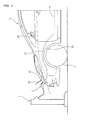
- FIG 1 is a schematic diagram showing a state during charging of a vehicle provided with a charging port locking device in a first embodiment.
- a charging port 4 is provided which is electrically connected to a vehicle battery 6 mounted on a vehicle floor 3 by a cable or code 43.
- This charging port is positioned at a height substantially equal to that of a top end of a tire wheel arch 33 and lower than a side mirror 34, and is closed by a charging lid 32 in a non-charging state.
- a charging stand 1 is provided with a charging connector 2 for supplying power, and, during a charging state, by opening the charging lid 32 and plugging the charging connector 2 in the charging port 4, a charging operation is performed.
- the vehicle in the first embodiment is provided with both a quick charging port for coupling with a quick or fast charger and a normal charging port when charging at home, etc.
- the operations are discussed during the normal charging process.
- the connection is of a relatively short period of time, so that such scenes are less frequent in which the vehicle is left for a long time.
- a lock mechanism according to the present invention may be also provided for a quick charge port side, as a matter of course.
- FIG. 2 is a schematic sectional view showing a state in which a charging connector in the first embodiment is connected to a charging port.
- the charging port 4 has a inserted or receiving member 41 fixed to a body part B1 through a bracket 74 for insertion of the charging connector 2, a cable 43 connected to the inserted member 41 in the interior of vehicle body, and a tube 42 covering a junction portion of this cable 43.
- a convex or protruding portion 4 1 a (engaged portion) is formed about the outer periphery of the inserted member 41, while an insertion hole is formed in an inner periphery of the inserted member 41, which allows the insertion only in a predetermined positional relationship to an insertion portion 22.
- the charging connector 2 is of a generally widely installed type and has a standard product size and format determined by the unified standard.
- the charging connector 2 is connected to the charging port 4 of the vehicle by the operator.
- the charging connector 2 has a grip portion 21 to be griped by the operator, the insertion portion 22 to be inserted with respect to the charging port 4 on the vehicle side, and an engaging member 23 capable of engagement with and release of the charging port 4 by the operator.
- the engaging member 23 engages with the convex portion 41a formed on the charging port 4, when the charging connector 2 is connected to the charging port 4, to thereby restrict the movement in a direction in which the charging connector 2 is released or plugged out of the charging port 4.
- the engaging member 23 is a member that rotates about a support point 23c (first pivot axis) which is fixed to a case member of the charging connector 2.
- the engaging member 23 is biased such that a release button 23a is positioned by an elastic member (not shown) at the upper side in FIG. 2 (so that a claw portion 23d is positioned at the lower side in FIG. 2 ).
- An end on the grip 21 is provided with a release button 23a for allowing an operator to press while holding the grip portion 21.
- a craw portion 23d is formed for engagement with the convex portion 41a.
- the claw portion 23d is formed in a claw shape with a curved surface portion 23d1 in which the tip portion has a smooth curved surface with respect to the insertion direction and a step portion 23d2 that forms an acute angle with respect to the release direction.
- the slope 41a1 is formed on the end face toward vehicle exterior while an engagement surface 41a2 extending generally vertically with respect to the release direction is formed on an end surface toward the vehicle interior so that an anisotropic or asymmetrical convex shape may be formed.
- the curved portion 23d1 of the tip portion of the claw portion 23d may get over the slope of the convex portion 41a. Thereafter, upon the step portion 23d2 passing through the engagement surface 41 a2, the claw portion 23d is pushed downward by the action of the elastic member (not shown), and the convex portion 41a and the claw portion 23d are engaged with each other. Note that it is also possible to insert the charging connector 2 while pressing the release button 23a.
- the movement in the releasing direction may be restricted by the engagement between the step portion 23d2 and the engagement surface 41 a2.
- the engaging member 23 is callused to rotate about the support point 23c in response to pressing down of the release button 23a to thereby move the claw portion 23d above the engagement surface 41a2 to release the engagement.
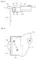
- FIG. 3 is a side view showing a structure of a lock mechanism in the first embodiment while FIG. 4 is a bottom view showing a structure of the lock mechanism in the first embodiment.
- a lock mechanism 7 is provided for restricting or limiting the rotation of the engaging member 23.
- the lock mechanism 7 includes a swing arm 71 that achieves, by being located in a separating direction between the claw portion 23 d and a convex portion 41a, a separation limiting or restricting state, and further achieves a separation permissible state by not being located in the separating direction.
- the lock mechanism further includes a lock actuator 73 for driving the swing arm 71 and a bracket 74 for fixing and supporting the lock actuator 73 and the inserted member 41 of the charging port 4.
- the bracket 74 includes an upper surface portion 74d for fixing and supporting the lock actuator 73 by bolts 74e, a support extension 74b extending from the upper surface portion to cover a movement range of the swing arm 71, a side surface portion 74c bent substantially perpendicular to the upper surface portion 74d for having the inserted member 41 etc. through bolts affixed thereto, and a cover member 74g for sandwiching the lock actuator 73 with the upper surface portion 74d.
- the upper surface portion 74d, the lock actuator 73, and the cover member 74g are assembled integrally by way of a plurality of bots 74e and nuts 74f.
- An opening 74a for compulsory or forcible operation during a failure is formed on the upper surface portion 74d for manipulation or operation of a fixing screw 72 (described below) so as to be rotatable by way of a screwdriver etc. by the driver with the hood being opened. The reason will be described below.
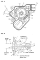
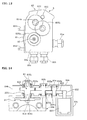
- FIG. 5 is an internal structural diagram showing a mechanical configuration of the lock mechanism in the first embodiment.
- the lock actuator 73 is provided with a connector portion 73a for connecting both an external power source and a controller, a motor 731 driven to rotate in accordance with a command signal, a worm gear 732 rotatable integrally with a rotor of the motor 731, a worm wheel meshed and integrally rotatable with the worm gear 732, a drive gear 734a which rotates integrally with the worm wheel 734 and has the same rotating shaft with a smaller diameter than the worm wheel 734, and a driven member 735 which meshes with the drive gear 734a and has a tooth surface on the outer circumference thereof.
- the driven member 735 is substantially fan-shaped is provided with a meshing portion 735a formed with a tooth surface on the outer periphery and a rotating shaft portion 735b to be assembled integrally with the swing arm 71.
- the swing arm 71 is a member that operates with the rotation shaft portion 735b as a rotation shaft. In other words, the swing arm 71 has a rotation axis the direction of which is different both from the insertion and release direction of the charging connector 2 and the direction of rotation axis of the engaging member 23.
- FIG 6 is a bottom view showing the structure or configuration of the swing arm of the lock mechanism in the first embodiment.
- the swing arm 71 includes a mounting portion 710 attached to the rotating shaft portion 735b of the lock actuator 73so as not to rotate relative thereto, and a cylindrical wall 713 of cylindrical shape covering the outer periphery of the mounting portion 710.
- the mounting portion 710 is formed with recesses 712 allocated in three places circumferentially, and by receiving concave portion 712 formed on the side of the rotation shaft portion 735b, a relative movement in the rotational direction will be restricted.
- a through hole 711 is formed in the center of the mounting portion 710 for passing through a fixing screw 72 to fastening or fixing together the swing arm 71 and the rotation shaft member 735 integrally.
- this through hole 711 causes an upper part of the swing arm 71 and the lock actuator 71 in a communicating state.
- a communication passage will be formed to function for communicating the hot water so that the frozen state will be quickly improved.
- the fixing screw 72 is fixed by a female screw portion provided on the side of the rotating shaft portion 735, and both the rotating shaft portion 735 and the swing arm 71 will thus be operated integrally.
- a tightening direction of the fixing screw 72 is set to be the same as a direction in which the swing arm 71 is rotated in the unlocking direction. That is, even if a failure or the like occurs in the lock actuator 73 and a release operation is no longer possible at all, by tightening the fixing screw 72 allows the swing arm 71 to rotate in the releasing direction.
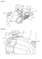
- FIG. 7 is a schematic perspective view showing a state in which a charging connector and a charging port are connected to each other. More specifically with reference to FIGS 2 and 7 , the fixing screw 72 is provided in an opening 74a for a compulsory operation during a failure so as to be exposed within a bonnet hood. Since a hood release lever in the passenger compartment is typically operated in order to open the hood, the fixing screw is thus considered to be disposed at an easily accessible position once the release lever is opened. In contrast, the fixing screw 72 is not disposed at an easily accessible position even if a charging lid 32 is opened. Therefore, the arrangement is made so as not to be freely accessible by others who is inaccessible in the passenger compartment. Further, since the fixing screw is configured to be operative easily with a Phillips screwdriver or the like, available in an onboard tool kit or the like, it is releasable by the operator.
- An arm member 71d of the plate shape extends from the cylindrical wall 713 on the left side in FIG. 6 .
- the arm member 71d is expanded in a fan shape at the tip and is designed to overlap with a claw portion 23d in a top view (i.e., corresponding to a state in which the arm member 7 1 d is located in the separation direction of the engaging member).
- the arm member 71d is formed with a lightening portion 71d1 to reduce weight and with the ribs 714 to ensure the required strength.
- the swing arm 71 is molded of resin and formed in a shape vertically asymmetric in top view, as shown in FIG. 6 .
- an assumption is made in which the center of rotation of the swing arm 71 (point where the center of the swing arm 71 in the thickness direction and the rotation axis match) and the center of rotation of the engaging member 23 in a locked state (point where the center of the engaging member 23 in the width direction and the rotation axis match) are connected to define an axis O1 as a reference line in a top view.
- symmetric imaginary lines that are symmetric vertically are drawn by dotted lines. The relationship to these symmetric imaginary lines is now described.
- An upper part is considered to be a region in which the swing arm 71 escapes when the lock mechanism moving from the restricting state to the non-restriction state.
- an upper region above the axis O1 is defined as an escape region and a lower region below is defined as a transition region.
- the escape region and the transition region of the swing arm 71 are symmetrical to each other, a large area is present which is located in the escape region side farther of the claw portion 23d.
- following problems were present. That is, since the charging port 4 is disposed at a relatively lower position of the vehicle, such a situation is expected in which sherbet-like snow or muddy water fly up caused by other vehicles travelling nearby and scattered on the charging port 4. Also, when charging in the cryogenic environment, the mud or snow sherbet that has been scattered may freeze to form an obstacle shaped in icicles hanging from the arm member 71d of the swing arm 71 as a roof.
- the arm member 71d is cut out largely extending from the symmetrical imaginary line close to the claw portion 23d.
- the area 71d3 present in the escape region of the arm member 71d (a top view area on a side in a rotational direction to the restricting state with respect to a line connecting the rotation center of the swing arm 71 and the rotation center of the claw portion 23d when the claw portion 23 d is positioned in a separating direction) is set smaller than the area 71 d2 of the arm member 71d in the transition region (a top view area on a side in a rotational direction to the non-restriction state with respect to a line connecting the rotation center of the swing arm 71 and the rotation center of the claw portion 23d when the claw portion 23 d is positioned in a separating direction).
- the roof portion in the escape regions may be reduced so that the icicle like obstacles are hardly formed, which would enable to move the swing arm 71 smoothly during unlocking operation.
- the roof portion in the escape regions may be reduced so that the icicle like obstacles are hardly formed, which would enable to move the swing arm 71 smoothly during unlocking operation.
- a symmetrical shape is secured with reference to axis 01 as a reference line. That is, when the swing arm 71 is rotated by the operation of the lock actuator 73 and assuming an insufficient rotation due to failure or the like, the more the length of the outermost diameter portion 71 f is secured, more reliably the swing arm 71 may be positioned in the separating direction of the claw portion 23d.
- FIG. 8 is a perspective view in a state in which the charging connector is connected to the charging port in the first embodiment.
- the cover member 9 covers the lock mechanism 7 from the direction of insertion and removal i.e., plug-in and -out of the charging connector 2 and has an opening 91 for enabling the claw portion to be inserted and exposing a part of the swing arm 71.
- the operator inserts the charging connector 2 into the charging port 4 and operates the lock mechanism 7 to thereby start charging operation with the operator being left and unattended.
- the outermost diameter portion 7 1 f of the swing arm 71 is in a state of being exposed.
- a large gap between the outermost diameter portion 71f and the cover member 9 then it is possible to forcibly break and open the the swing arm 71 by placing a finger or the like into the gap. Therefore, the gap between the swing arm 71 and the cover member 9 is set narrow to the extent that both are not in not in contact.
- the relationship between the cover member 9 and the swing arm 71 is now detailed. As shown in FIG. 6 , the distance between the inner periphery of the cover 9 and the outermost diameter portion 71f of the swing arm 71 when rotated is set larger as the distance from the opening 91 is larger. Stated another way, if the charging connecter 2 is connected to the charging port 4 in a state in which dust and the like (chewing gum, mud, dust, etc.) is attached on the claw portion 23d, in response to a rotational movement of the swing arm 71, a sweeping operation is assured while scraping off these rubbishes.
- dust and the like chewing gum, mud, dust, etc.
- FIG. 9 is a schematic sectional view showing the positional relationship between the engaging member and the swing arm in the first embodiment.
- a predetermined gap a1 is provided between the upper surface of the swing arm 71 and the support extension 74b while a predetermined gap b1 is provided as well between the lower surface of the swing arm 71 and the claw portion 23d. Therefore, when the swing arm 71 is rotated, there will be no contact with the support extension 74b and the claw portion 23d, it is possible to actuate the swing arm 71 smoothly.
- the height of the area overlapping the step portion 23d2 with the engagement surface 41a2 is defined as c1, the relationship expressing c1 > (a1 +b1) is established.
- the engagement between the step portion 23d2 and the engagement surface 41 a2 will be maintained.
- FIG 10 is a schematic sectional view showing the positional relationship between the engaging member and the swing arm when the engaging member is forcibly moved in the separating direction.
- the rotation shaft of the swing arm 71 extends in a direction different from the insertion and removal direction of the charging connector 2, and has a rotation axis extending different from the direction of rotation axis of the engaging member 23. Stated even more specifically, the direction of rotation shaft of the swing arm 71 and the direction of the rotation shaft of the engaging member 23 are not parallel to each other.
- the engaging member is restricted or limited in the movement by interposing the swing arm 71 in the separating direction of the claw portion 23d, and the extension support 74b is provided further.
- the first embodiment exhibits the operational effects enumerated below:
- FIG. 11 is a schematic sectional view showing the positional relationship between the engaging member and the swing arm.
- the rotational axis of the swing arm 71 is disposed on an orthogonal surface of the insertion and removal direction of the engaging member 23.
- a predetermined angle ⁇ is provided with respect to a direction intersecting the plane perpendicular to the direction of insertion and removal. The predetermined angle ⁇ is set in the tilting direction on the claw portion 23d side.
- FIG. 12 is a bottom view showing the configuration of the swing arm of the lock mechanism of the third embodiment.
- a asymmetric shape is used with respect to the 01 axis
- a symmetrical shape presents a point of difference.
- the side end shape of the claw portion 23d is formed to coincide with the shape of the side end part 71 g of the swing arm 71.
- FIG. 13 is a plan view illustrating the configuration of the lock mechanism of the fourth embodiment
- FIG 14 is an inter- gear shaft cross-sectional view of the lock mechanism of the fourth embodiment.
- a rotary plate 81 is rotatable, which represents a point of difference over the first embodiment.
- the lock mechanism 8 has a lock actuator 83 and is composed of a plurality of gear sets accommodated in a housing 84 of the lock actuator 83 and a rotary plate 81.
- the housing 84 is provided with a lower housing 84b open at the top, an upper housing 84a covering the upper surface of the lower housing 84b, a bracket 84b formed below the rotary plate 81 for mounting the charging port 4 and the like, and a motor accommodating portion 84c for accommodating the motor 831. Further, the bracket 84b is provided with a support member 85b for fixedly supporting on vehicle side and harness ports 85a, 85b, 85c for connecting the motor 831, sensors (not shown) and the like with harness.
- a pinion 832 which is connected to the motor 831 is constantly meshed with a first gear 833 integrally rotatable with a first rotation shaft 834.
- a first rotation shaft gear 834a is formed on the outer periphery of the first rotation shaft 834 and is in a constantly meshed relation with a second gear 835a integrally rotatable with a second rotation shaft 835.
- the second gear 835a is meshed constantly with a third gear 836a rotatable integrally with a third rotation shaft 836.
- the first rotation shaft 834, the second rotation shaft 835 and the third rotation shaft 836 are rotatably supported on bearings 834b, 835b, 836b with respect to the upper housing 84a and the lower housing 84b.
- Screw holes 836c are formed in the axial portion of the third rotation shaft 836 at both ends, and the rotary plate 81 is fixed from the side of the lower housing 84b by a screw 82a.
- the emergency screw 82 can be rotated by a Phillips screwdriver, or a hex bolt portion formed on the outer periphery may be turned with a wrench.
- the tightening direction of the emergency screw 82 is set to be the same as the unlocking direction of the rotary plate 81. That is, even if a failure or the like occurs in the lock actuator 83 and the release operation is no longer possible at all, by tightening the emergency screw 82, it is possible to rotate the rotary plate 81 in the unlocking direction.
- This emergency screw 82 is arranged to be exposed within a hood. To open the hood, operation of a hood release lever within a passenger compartment is a normal process. Once this release lever is operable, the emergency screw is provided at a position easily accessible. Moreover, the position is selected so as not to be accessible even if a charging lid 32 is opened.
- FIG 15 is a top view showing the configuration of the rotary plate in the fourth embodiment.
- the rotary plate 81 is of a generally disc shaped with a thorough hole with width across flats 811 for receiving the third rotation shaft 836, and has a notch 812 cut out partly and circumferentially and a plate portion 813 not being cut out.
- the positional relations between the rotary plate 81 and the claw portion 23d as shown in FIG. 15 reflects a state in which the lock mechanism 8 is in non-restriction state and the charging connector 2 is inserted into the charging port 4. Respective positional relations are described below with identifying the center position of the claw portion 23d as 0° and a clockwise direction as positive.
- the notch portion 812 is formed in a range spanning in the circumferential direction from -65 ° to +30 °, i.e. in a size of in a size of 95 °. Since the tip of the claw portion 23d occupies a size of about 40 ° at the maximum in the circumferential direction, the notch portion 812 may be said to have at least twice the length of the rotational direction of the claw portion 23d. Consequently, when outputting the release command to the lock actuator 83, even if the position is excessively returned back due to failure or the like, it is possible to maintain the released state.
- the circumferential length of the notch or cutout portion 812 is set sufficiently longer than the circumferential length of the pawl portion 23d for the following reason. That is, if the dust or the like is attached to the notch or cutout portion 812, the dust of sticky nature may clog the cutout portion 812. In this case, if the circumferential length of the cutout portion 812 is short, the dust may adhere more strongly over the both end portions of the cutout portion 812. In contrast, by lengthening the circumferential length of the 812 cutout portion, the state in which the dust adheres across the opposite ends may be avoided. Also, even if dust adheres only at one end, since the other side forms an open end, dust can easily fall downward to thereby eliminate the dust or rubbish appropriately.
- the plate portion 813 is formed over a range spanning between +30 ° and +295 °, i.e. in a size of 265 °.
- the radial end of the plate portion 813 is formed with a smooth end over the entire circumference.
- the notch end 813a that represents both a circumferential starting end of the plate portion 813 and a circumferential end of the notch portion 812 is shaped to be inclined with respect to the radial direction. As shown in a partial enlarged view of FIG 15 , the notch end portion 813a is inclined to a narrow side of the region of the notch portion 812.
- the notch end portion 813a is inclined so as to be roughly parallel with the side end on the rotation direction of the claw portion 23d.
- FIG 16 is a sectional view in which a sectional shape along the section line drawn in the circumferential direction of the rotary plate of FIG. 15 is extended linearly.
- the first rotary plate surface 813b shown in the range between 30 ° and 165 ° is formed with a tapered surface approaching the claw portion 23d toward the rotation direction.
- the rotary plate 81 may be interposed in the separating direction of the claw portion 23d. Further, even if bitten or seized on the claw portion 23d, a relatively easy release of the seizure is assured because of small frictional resistance along with easy deformation.
- a second rotary plate surface 814b continuous with the first rotary plate surface 813b is formed as a horizontal surface. That is, when forming the tapered surface continuously along the rotational direction, the overall thickness of the rotary plate 81 would be thicker and on-vehicle mounted would deteriorate. Further, if a failure or the like occurs in the motor 831 and the motor undergoes an over-speed, there is a possibility that an excessive bite in the claw portion 23d occurs and hinders the release operation. Therefore, by forming the horizontal surface, a compactness is achieved and an excessive biting or jamming at the time of a failure is avoided.
- the second rotary plate surface 814b is formed over the range of 130 °, which is greater than the area occupied by the claw portion 23. Therefore, even if a failure or the like occurs with the motor 831 resulting in an excessive rotation, it is possible to maintain the state of restricting or limiting the claw portion 23d.
- FIG. 17 is a schematic sectional view showing the positional relationship between the engaging member and the rotary plate in the fourth embodiment.
- a predetermined gap d1 is provided between the lower surface of the rotary plate 81 and the claw portion 23d.
- the gap d1 may be slightly different depending upon a rotation stop position of the rotary plate 81, it is configured to provide a predetermined gap relative to the second rotary plate surface 814b. Therefore, when the rotary plate 81 is rotated, no contact with the claw portion 23d occurs so that a smooth operation of the rotary plate may be ensured.
- the height of the overlapping area between the step portion 23d and the engaging surface 41a is defined as c1, it is configured that the relationship, c1>d1, is established. Thus, even if the gap disappears due to forcible push-up operation of the claw portion 23d, the engagement between the step portion 23d2 and the engaging surface 41a2 is maintained.
- the rotation shaft of the rotary plate 81 extends in a direction different from the insertion and removal direction of the charging connector 2, and has a rotation axis (second rotation shaft) extending in a direction different from the direction of the rotation axis (first rotation shaft) of the engaging member 23. More specifically, the direction of the rotation shaft of the rotary plate 81 is not in parallel with the rotation shaft of the engaging member 23, and the rotary plate 81 is configured to be interposed in the separating direction of the claw portion 23b to restrict or limit movement thereof.
- a lower housing 84b is also provided. Therefore, an excessive force input from the claw portion 23d would not exert in the rotational direction of the rotary plate 81 so that it is not necessary for the rotary plate 81 to be formed rigid in the rotational direction. In addition, without requiring the structure near the rotation shaft to be strong, a sufficient limiting or restricting state may be achieved.
- the fourth embodiment exhibits the effects enumerated effects below:
- a charging port installed in the front of the vehicle the same may be provided rearward of the vehicle or on the side of the vehicle.
- the description has been given of an electric vehicle, but a plug-in hybrid vehicle or the like is equally applicable.
Landscapes
- Engineering & Computer Science (AREA)
- Power Engineering (AREA)
- Transportation (AREA)
- Mechanical Engineering (AREA)
- Life Sciences & Earth Sciences (AREA)
- Sustainable Development (AREA)
- Sustainable Energy (AREA)
- Computer Security & Cryptography (AREA)
- Electric Propulsion And Braking For Vehicles (AREA)
- Details Of Connecting Devices For Male And Female Coupling (AREA)
- Arrangement Or Mounting Of Propulsion Units For Vehicles (AREA)
Abstract
Description
- The present invention relates to a locking device of a charging port for charging a battery mounted on the vehicle.
- As a technique related to a charging port locking device, the technique is disclosed as described in Patent Document 1. In this publication, a charging connector for connecting a charging station as a power supply unit to a charging port of an electric vehicle to allow a charging operation by connecting the charging connector to the charging port.
- Patent Document 1: Japanese Laid-Open Application Publication No.
H9-161884 - Here, in a vehicle such as an electric vehicle equipped with a battery of relatively large capacity, when charging at the charging station, a charging operation over a relatively long time may be considered. At this time, if the connection between the charging connector and charging port is inadvertently, i.e., due to factors other than the driver's intention disconnected or disengaged, charging will not be performed. This would lead to a situation in which, even if the driver returns after a planned charging period, charging is not yet completed.
- The present invention has been made in view of the above problems, and aims to provide a charging port lock device capable of avoiding a situation in which the connection between the charging connector and the charging port is released unexpectedly during charging
- In order to achieve the above object, in the charging port lock device according to the present invention, a charging port to which electric power from an external power source is supplied through a charging connector by the operation of an operator is provided with a cover that covers a lock mechanism for achieving both locked and unlocked states in response to rotational movement of a restricting or limiting member from a charging connector insertion and removal side. The cover member also has an opening for insertion of an engaging member. The distance between the inner periphery surface of the cover member at the side of the lock mechanism and a rotational movement locus of the restricting member is configured to be greater with the distance from the opening in the rotational direction.
- Therefore, it is possible to prevent the charging connector from being disengaged accidentally by connecting the charging connector to the charging port and subsequently to restrict or limit the operation of the engaging member by the restricting member. Further, by providing the restricting or limiting mechanism on the vehicle side, it is possible to perform the restricting operation regardless of a configuration of the charging connector. Furthermore, it is possible to allow dust scraped by the restricting member to fall down appropriately so as to avoid dust clogging etc.
-
-
FIG. 1 is a schematic diagram showing a state during charging of a vehicle provided with a charging port locking device in a first embodiment; -
FIG. 2 is a schematic sectional view showing a state in which a charging connector and a charging port are being connected in the first embodiment; -
FIG. 3 is a side view showing a structure of a lock mechanism in the first embodiment; -
FIG. 4 is a bottom view showing a structure of the lock mechanism in the first embodiment; -
FIG. 5 is an internal structural diagram showing a mechanical configuration of the lock mechanism in the first embodiment; -
FIG. 6 is a bottom view showing a configuration of the swing arm of the lock mechanism in the first embodiment; -
FIG. 7 is a schematic perspective view of a state in which the charging connector and the charging port are connected to each other in the first embodiment; -
FIG. 8 is a perspective view of a state in which the charging connector and the charging port are connected to each other in the first embodiment; -
FIG. 9 is a schematic sectional view showing a positional relationship between the engaging member and the swing arm in the first embodiment; -
FIG.10 is a schematic sectional view showing a positional relationship between the engaging member and the swing arm when the engaging member is forcibly operated in the detaching direction in the first embodiment; -
FIG. 11 is a schematic sectional view showing a positional relationship between the engaging member and the swing arm in a second embodiment; -
FIG. 12 is a bottom view showing a configuration of the swing arm of the lock mechanism in a third embodiment; -
FIG. 13 is a top view showing a configuration of the lock mechanism in a fourth embodiment; -
FIG. 14 is a gear shaft cross-sectional view of the lock mechanism in a fourth embodiment; -
FIG. 15 is a top view showing a configuration of a rotary plate in the fourth embodiment; -
FIG. 16 is a sectional view with a sectional shape being extended linearly along a section line drawn in the circumferential direction of the rotary plate inFIG. 15 ; and -
FIG. 17 is a schematic sectional view showing the positional relationship between the engaging member and the rotary plate. -
- 1
- charging Stand
- 2
- charging connector
- 4
- charging port
- 6
- vehicle mounted battery
- 7
- lock mechanism
- 8
- lock mechanism
- 9
- cover member
- 23
- engaging member
- 23a
- release button
- 23c
- support point
- 23d
- claw portion
- 31
- hood
- 32
- charging lid
- 41
- inserted member
- 41a
- convex portion
- 71
- swing arm
- 71f
- outermost diameter portion
- 71g
- side end part viewed from the top
- 72
- fixing screw
- 73
- lock actuator
- 74a
- opening for compulsory operation upon occurrence of a failure
- 74b
- support extension
- 74g
- cover member
- 81
- rotary plate
- 82
- emergency screw
- 83
- lock actuator
-
FIG 1 is a schematic diagram showing a state during charging of a vehicle provided with a charging port locking device in a first embodiment. In front of thevehicle 3, and forward of ahood 31, a chargingport 4 is provided which is electrically connected to avehicle battery 6 mounted on avehicle floor 3 by a cable orcode 43. This charging port is positioned at a height substantially equal to that of a top end of atire wheel arch 33 and lower than aside mirror 34, and is closed by a charginglid 32 in a non-charging state. A charging stand 1 is provided with a chargingconnector 2 for supplying power, and, during a charging state, by opening the charginglid 32 and plugging the chargingconnector 2 in the chargingport 4, a charging operation is performed. Note that the vehicle in the first embodiment is provided with both a quick charging port for coupling with a quick or fast charger and a normal charging port when charging at home, etc. In the first embodiment, the operations are discussed during the normal charging process. When using the fast charging port, the connection is of a relatively short period of time, so that such scenes are less frequent in which the vehicle is left for a long time. Note that a lock mechanism according to the present invention may be also provided for a quick charge port side, as a matter of course. -
FIG. 2 is a schematic sectional view showing a state in which a charging connector in the first embodiment is connected to a charging port. The chargingport 4 has a inserted or receivingmember 41 fixed to a body part B1 through abracket 74 for insertion of the chargingconnector 2, acable 43 connected to the insertedmember 41 in the interior of vehicle body, and atube 42 covering a junction portion of thiscable 43. A convex or protrudingportion 4 1 a (engaged portion) is formed about the outer periphery of the insertedmember 41, while an insertion hole is formed in an inner periphery of the insertedmember 41, which allows the insertion only in a predetermined positional relationship to aninsertion portion 22. - The charging
connector 2 is of a generally widely installed type and has a standard product size and format determined by the unified standard. The chargingconnector 2 is connected to the chargingport 4 of the vehicle by the operator. The chargingconnector 2 has agrip portion 21 to be griped by the operator, theinsertion portion 22 to be inserted with respect to the chargingport 4 on the vehicle side, and an engagingmember 23 capable of engagement with and release of the chargingport 4 by the operator. The engagingmember 23 engages with theconvex portion 41a formed on the chargingport 4, when the chargingconnector 2 is connected to the chargingport 4, to thereby restrict the movement in a direction in which the chargingconnector 2 is released or plugged out of the chargingport 4. - The engaging
member 23 is a member that rotates about asupport point 23c (first pivot axis) which is fixed to a case member of the chargingconnector 2. The engagingmember 23 is biased such that arelease button 23a is positioned by an elastic member (not shown) at the upper side inFIG. 2 (so that aclaw portion 23d is positioned at the lower side inFIG. 2 ). An end on thegrip 21 is provided with arelease button 23a for allowing an operator to press while holding thegrip portion 21. On the other end of theinsertion portion 22, acraw portion 23d is formed for engagement with theconvex portion 41a. Theclaw portion 23d is formed in a claw shape with a curved surface portion 23d1 in which the tip portion has a smooth curved surface with respect to the insertion direction and a step portion 23d2 that forms an acute angle with respect to the release direction. On the other hand, the slope 41a1 is formed on the end face toward vehicle exterior while an engagement surface 41a2 extending generally vertically with respect to the release direction is formed on an end surface toward the vehicle interior so that an anisotropic or asymmetrical convex shape may be formed. - When the charging
connector 2 is inserted into the chargingport 4, without having to act on therelease button 23a for special operations, the curved portion 23d1 of the tip portion of theclaw portion 23d may get over the slope of theconvex portion 41a. Thereafter, upon the step portion 23d2 passing through theengagement surface 41 a2, theclaw portion 23d is pushed downward by the action of the elastic member (not shown), and theconvex portion 41a and theclaw portion 23d are engaged with each other. Note that it is also possible to insert the chargingconnector 2 while pressing therelease button 23a. Thus, even if the operator would pull the chargingconnector 2 in the direction of extracting or releasing the chargingconnector 2 in a state where the operator does not operate therelease button 23a, the movement in the releasing direction may be restricted by the engagement between the step portion 23d2 and theengagement surface 41 a2. In order to release this engagement, the engagingmember 23 is callused to rotate about thesupport point 23c in response to pressing down of therelease button 23a to thereby move theclaw portion 23d above the engagement surface 41a2 to release the engagement. -
FIG. 3 is a side view showing a structure of a lock mechanism in the first embodiment whileFIG. 4 is a bottom view showing a structure of the lock mechanism in the first embodiment. Above the chargingport 4, alock mechanism 7 is provided for restricting or limiting the rotation of the engagingmember 23. Thelock mechanism 7 includes aswing arm 71 that achieves, by being located in a separating direction between theclaw portion 23 d and aconvex portion 41a, a separation limiting or restricting state, and further achieves a separation permissible state by not being located in the separating direction. The lock mechanism further includes alock actuator 73 for driving theswing arm 71 and abracket 74 for fixing and supporting thelock actuator 73 and the insertedmember 41 of the chargingport 4. - As shown in the side view in
FIG 3 as well as in the bottom view ofFIG. 4 , thebracket 74 includes anupper surface portion 74d for fixing and supporting thelock actuator 73 bybolts 74e, asupport extension 74b extending from the upper surface portion to cover a movement range of theswing arm 71, aside surface portion 74c bent substantially perpendicular to theupper surface portion 74d for having the insertedmember 41 etc. through bolts affixed thereto, and acover member 74g for sandwiching thelock actuator 73 with the upper surface portion 74d.Theupper surface portion 74d, thelock actuator 73, and thecover member 74g are assembled integrally by way of a plurality ofbots 74e and nuts 74f. Anopening 74a for compulsory or forcible operation during a failure (seeFIGS. 2 ,7 , etc.) is formed on theupper surface portion 74d for manipulation or operation of a fixing screw 72 (described below) so as to be rotatable by way of a screwdriver etc. by the driver with the hood being opened. The reason will be described below. -
FIG. 5 is an internal structural diagram showing a mechanical configuration of the lock mechanism in the first embodiment. Thelock actuator 73 is provided with aconnector portion 73a for connecting both an external power source and a controller, amotor 731 driven to rotate in accordance with a command signal, aworm gear 732 rotatable integrally with a rotor of themotor 731, a worm wheel meshed and integrally rotatable with theworm gear 732, adrive gear 734a which rotates integrally with theworm wheel 734 and has the same rotating shaft with a smaller diameter than theworm wheel 734, and a drivenmember 735 which meshes with thedrive gear 734a and has a tooth surface on the outer circumference thereof. The drivenmember 735 is substantially fan-shaped is provided with a meshingportion 735a formed with a tooth surface on the outer periphery and arotating shaft portion 735b to be assembled integrally with theswing arm 71. Theswing arm 71 is a member that operates with therotation shaft portion 735b as a rotation shaft. In other words, theswing arm 71 has a rotation axis the direction of which is different both from the insertion and release direction of the chargingconnector 2 and the direction of rotation axis of the engagingmember 23. Since, in the lock mechanism in the first embodiment, it is sufficient for theswing arm 71 to rotate within a predetermined angular range, even with the use of the drivenmember 73 provided with tooth surface only partly, an operation is allowable with a small sized motor while ensuring a sufficient torque. Note that this lock actuator is being adapted to the automatic door lock mechanism of a vehicle in general, it is possible to reduce the manufacturing cost when adopted as such without substantial modification of the components thereof. -
FIG 6 is a bottom view showing the structure or configuration of the swing arm of the lock mechanism in the first embodiment. Theswing arm 71 includes a mountingportion 710 attached to therotating shaft portion 735b of the lock actuator 73so as not to rotate relative thereto, and acylindrical wall 713 of cylindrical shape covering the outer periphery of the mountingportion 710. The mountingportion 710 is formed withrecesses 712 allocated in three places circumferentially, and by receivingconcave portion 712 formed on the side of therotation shaft portion 735b, a relative movement in the rotational direction will be restricted. A throughhole 711 is formed in the center of the mountingportion 710 for passing through a fixingscrew 72 to fastening or fixing together theswing arm 71 and therotation shaft member 735 integrally. Since this throughhole 711 causes an upper part of theswing arm 71 and thelock actuator 71 in a communicating state. Thus, even if theswing arm 71 will be difficult to be operated due to freezing or the like, by pouring or applying hot water to improve the frozen state, a communication passage will be formed to function for communicating the hot water so that the frozen state will be quickly improved. The fixingscrew 72 is fixed by a female screw portion provided on the side of therotating shaft portion 735, and both therotating shaft portion 735 and theswing arm 71 will thus be operated integrally. - Note that a tightening direction of the fixing
screw 72 is set to be the same as a direction in which theswing arm 71 is rotated in the unlocking direction. That is, even if a failure or the like occurs in thelock actuator 73 and a release operation is no longer possible at all, by tightening the fixingscrew 72 allows theswing arm 71 to rotate in the releasing direction. -
FIG. 7 is a schematic perspective view showing a state in which a charging connector and a charging port are connected to each other. More specifically with reference toFIGS 2 and7 , the fixingscrew 72 is provided in anopening 74a for a compulsory operation during a failure so as to be exposed within a bonnet hood. Since a hood release lever in the passenger compartment is typically operated in order to open the hood, the fixing screw is thus considered to be disposed at an easily accessible position once the release lever is opened. In contrast, the fixingscrew 72 is not disposed at an easily accessible position even if a charginglid 32 is opened. Therefore, the arrangement is made so as not to be freely accessible by others who is inaccessible in the passenger compartment. Further, since the fixing screw is configured to be operative easily with a Phillips screwdriver or the like, available in an onboard tool kit or the like, it is releasable by the operator. - An
arm member 71d of the plate shape extends from thecylindrical wall 713 on the left side inFIG. 6 . Thearm member 71d is expanded in a fan shape at the tip and is designed to overlap with aclaw portion 23d in a top view (i.e., corresponding to a state in which thearm member 7 1 d is located in the separation direction of the engaging member). Thearm member 71d is formed with a lightening portion 71d1 to reduce weight and with theribs 714 to ensure the required strength. - The
swing arm 71 is molded of resin and formed in a shape vertically asymmetric in top view, as shown inFIG. 6 . Hereinafter, an assumption is made in which the center of rotation of the swing arm 71 (point where the center of theswing arm 71 in the thickness direction and the rotation axis match) and the center of rotation of the engagingmember 23 in a locked state (point where the center of the engagingmember 23 in the width direction and the rotation axis match) are connected to define an axis O1 as a reference line in a top view. Then, symmetric imaginary lines that are symmetric vertically are drawn by dotted lines. The relationship to these symmetric imaginary lines is now described. An upper part is considered to be a region in which theswing arm 71 escapes when the lock mechanism moving from the restricting state to the non-restriction state. Thus, an upper region above the axis O1 is defined as an escape region and a lower region below is defined as a transition region. - If the escape region and the transition region of the
swing arm 71 are symmetrical to each other, a large area is present which is located in the escape region side farther of theclaw portion 23d. In this case, following problems were present. That is, since the chargingport 4 is disposed at a relatively lower position of the vehicle, such a situation is expected in which sherbet-like snow or muddy water fly up caused by other vehicles travelling nearby and scattered on the chargingport 4. Also, when charging in the cryogenic environment, the mud or snow sherbet that has been scattered may freeze to form an obstacle shaped in icicles hanging from thearm member 71d of theswing arm 71 as a roof. In this case, with a large region of thearm member 71d in the escape region, it is likely that obstacles of icicle shape will be formed, so that, even if a lock release command is output, the obstacle on theswing arm 71 might engage with theclaw portion 23d, locking stated will not be released. - Therefore, it has been decided that the
arm member 71d is cut out largely extending from the symmetrical imaginary line close to theclaw portion 23d. In other words, the area 71d3 present in the escape region of thearm member 71d (a top view area on a side in a rotational direction to the restricting state with respect to a line connecting the rotation center of theswing arm 71 and the rotation center of theclaw portion 23d when theclaw portion 23 d is positioned in a separating direction) is set smaller than thearea 71 d2 of thearm member 71d in the transition region (a top view area on a side in a rotational direction to the non-restriction state with respect to a line connecting the rotation center of theswing arm 71 and the rotation center of theclaw portion 23d when theclaw portion 23 d is positioned in a separating direction). Therefore, the roof portion in the escape regions may be reduced so that the icicle like obstacles are hardly formed, which would enable to move theswing arm 71 smoothly during unlocking operation. In particular, since by cutting out the area barely overlapping theclaw portion 23d in top view , it is possible to reduce the possibility that the obstacles and the like will be formed while reliably restricting movement of theclaw portion 23d in a separating direction reliably. - Then, with respect to a top view shape of the
outermost diameter portion 71f of theswing arm 71, a symmetrical shape is secured with reference toaxis 01 as a reference line. That is, when theswing arm 71 is rotated by the operation of thelock actuator 73 and assuming an insufficient rotation due to failure or the like, the more the length of theoutermost diameter portion 71 f is secured, more reliably theswing arm 71 may be positioned in the separating direction of theclaw portion 23d. -
FIG. 8 is a perspective view in a state in which the charging connector is connected to the charging port in the first embodiment. By inserting the chargingconnector 2 into the chargingport 4, and positioning theswing arm 71 in the separating direction of theclaw portion 23d due to operation of thelock mechanism 7, theclaw portion 23d cannot move in the separating direction even if therelease button 23a is pressed. Thus, it is impossible to release the engagement between theconvex portion 41 a and theclaw portion 23d so that the chargingconnector 2 is prohibited from being plugged out or withdrawn. At this time, the chargingport 4 of the vehicle is protected from the entry of dust or the like into thelock mechanism 7 by providing acover member 9. Thecover member 9 covers thelock mechanism 7 from the direction of insertion and removal i.e., plug-in and -out of the chargingconnector 2 and has anopening 91 for enabling the claw portion to be inserted and exposing a part of theswing arm 71. - It is assumed that the operator inserts the charging
connector 2 into the chargingport 4 and operates thelock mechanism 7 to thereby start charging operation with the operator being left and unattended. In this state, as shown inFIG. 8 , theoutermost diameter portion 7 1 f of theswing arm 71 is in a state of being exposed. Suppose that a large gap between theoutermost diameter portion 71f and thecover member 9, then it is possible to forcibly break and open the theswing arm 71 by placing a finger or the like into the gap. Therefore, the gap between theswing arm 71 and thecover member 9 is set narrow to the extent that both are not in not in contact. - Further, in a state in which the charging
connector 2 is being restricted to be removed by thelock mechanism 7, all of theopenings 91 is set closed by theoutermost diameter portion 71f of theswing arm 71. In other words, the length of theoutermost diameter portion 71f in the rotational direction is set longer than the width of opening 91 (the length along the rotational direction). This arrangement is intended, as described above, to exclude the possibility that theswing arm 71 may be forcibly broken by placing a finger or the like into a gap which would be otherwise present between ends of theopening 91 and the end of theswing arm 71. - Further, coming back again to
FIG. 6 , the relationship between thecover member 9 and theswing arm 71 is now detailed. As shown inFIG. 6 , the distance between the inner periphery of thecover 9 and theoutermost diameter portion 71f of theswing arm 71 when rotated is set larger as the distance from theopening 91 is larger. Stated another way, if the chargingconnecter 2 is connected to the chargingport 4 in a state in which dust and the like (chewing gum, mud, dust, etc.) is attached on theclaw portion 23d, in response to a rotational movement of theswing arm 71, a sweeping operation is assured while scraping off these rubbishes. In this instance, assuming that the distance between the inner periphery surface of thecover member 9 and the locus ofoutermost diameter portion 71f would be set narrower gradually, the rubbish scraped out will enter this gap so that a large resistance will be encountered and the operation of theswing arm 71 will be impaired. Thus, by setting the distance between the inner periphery of thecover member 9 and theoutermost diameter portion 71f is set greater in accordance with the distance from theopening 91, the scraped out rubbish will be appropriately falls down and an eventual dust clogging may be avoided. -
FIG. 9 is a schematic sectional view showing the positional relationship between the engaging member and the swing arm in the first embodiment. A predetermined gap a1 is provided between the upper surface of theswing arm 71 and thesupport extension 74b while a predetermined gap b1 is provided as well between the lower surface of theswing arm 71 and theclaw portion 23d. Therefore, when theswing arm 71 is rotated, there will be no contact with thesupport extension 74b and theclaw portion 23d, it is possible to actuate theswing arm 71 smoothly. Note that, when viewed from the direction of connecting or disconnecting the chargingconnector 2, if the height of the area overlapping the step portion 23d2 with the engagement surface 41a2 is defined as c1, the relationship expressing c1 > (a1 +b1) is established. Thus, as shown inFIG. 10 , even if both the gaps a1 and b1 would disappear due to a forcible push-up of theclaw portion 23d, the engagement between the step portion 23d2 and theengagement surface 41 a2 will be maintained. -
FIG 10 is a schematic sectional view showing the positional relationship between the engaging member and the swing arm when the engaging member is forcibly moved in the separating direction. Assuming that, in a state in which movement of the engagingmember 23 in the separating direction is being restricted and therelease button 23 is pressed down, the upper surface of theclaw portion 23d will contact the lower surface of theswing arm 71 to push up theswing arm 71. At this time, since the swing arm itself is made of resin and therotation shaft 735b is not designed to be sufficiently rigid, theswing arm 71 will be pushed up vertically with ease due to deformation of theswing arm 71 or inclination of the rotation shaft. However, due to provision of thesupport extension 74b, the contact with thissupport extension 74b will suppress further deformation. In addition, since a force is applied only in the thickness direction of theswing arm 71, despite the swing arm being of resin, a sufficient strength is secured against a compression force. More specifically, the rotation shaft of theswing arm 71 extends in a direction different from the insertion and removal direction of the chargingconnector 2, and has a rotation axis extending different from the direction of rotation axis of the engagingmember 23. Stated even more specifically, the direction of rotation shaft of theswing arm 71 and the direction of the rotation shaft of the engagingmember 23 are not parallel to each other. The engaging member is restricted or limited in the movement by interposing theswing arm 71 in the separating direction of theclaw portion 23d, and theextension support 74b is provided further. Thus, even if the excessive force is input from theclaw portion 23, since the force does not act in the rotational direction of theswing arm 71, it is not necessary to form theswing arm 71 rigid with respect to rotational direction. Moreover, it is possible to achieve and maintain a sufficient restricting state without requiring the structure around the rotational shaft strong. - As described above, the first embodiment exhibits the operational effects enumerated below:
- (1) A charging
port 4 is provided that has aconvex portion 41a (engaged portion) for engaging aclaw portion 23d (engaging portion) of a chargingconnector 2 by an operation of the operator. Further, alock mechanism 7 is provided that achieves a lock state that restricts release from the engaged state by restricting or limiting the releasing operation of theclaw portion 23d due to movement of the swing arm 71 (restricting member) in the locking direction and an unlock state that allows the releasing operation through a movement in the unlocking direction opposite to the locking direction. Still further, acover member 9 is provided that covers thelock mechanism 7 from the insertion and removal direction of the chargingconnector 2 and that is formed with an opening for enabling the engagingmember 23 to be inserted. The distance between the inner periphery surface of thecover member 9 on the side of thelock mechanism 7 and the rotation locus of theswing arm 71 is set greater as the distance from theopening 91 increases. Therefore, it is possible to prevent the chargingconnector 2 from being released unexpectedly during charging. Further, provision of a lock mechanism on vehicle side makes it possible to be used in association with existing charging stations. Further, it is possible that dust scraped by theswing arm 71 may fall down to therby avoid the dust clogging. - (2) The restricting member is a
swing arm 71 that extends radially from the center of rotation. In the case of theswing arm 71, if dust or rubbish adheres, there is a risk that the associated load has an impact on the entire arm to deteriorate the operability. In contrast, by avoiding clogging of dust or rubbish, a stable operation may be achieved. - Now, a description is given of a second embodiment. Since a basic configuration is the same as in the first embodiment, only the points of difference are discussed.
FIG. 11 is a schematic sectional view showing the positional relationship between the engaging member and the swing arm. In the first embodiment, the rotational axis of theswing arm 71 is disposed on an orthogonal surface of the insertion and removal direction of the engagingmember 23. In contrast, in the second embodiment, a predetermined angle α is provided with respect to a direction intersecting the plane perpendicular to the direction of insertion and removal. The predetermined angle α is set in the tilting direction on theclaw portion 23d side. Thus, even if theclaw portion 23d is pushed up by force, it is possible to restrict stably by receiving the force in the axial shaft of the rotary axis of theswing arm 71. Besides, while an example of forming asupport extension 74b is provided also in the second embodiment, when the strength is secured, the support extension may not be provided in particular. - Now, a description is given of a third embodiment. Since a basic configuration is the same as in the first embodiment, only the points of difference are discussed.
FIG. 12 is a bottom view showing the configuration of the swing arm of the lock mechanism of the third embodiment. Whereas in the first embodiment, a asymmetric shape is used with respect to the 01 axis, in the third embodiment, a symmetrical shape presents a point of difference. Further, when transitioning to the restricting or limiting state in response to rotational movement of theswing ann 71, in a top view, the side end shape of theclaw portion 23d is formed to coincide with the shape of theside end part 71 g of theswing arm 71. Therefore, when transitioning to the limiting or restricting state, in a top view, such a situation may arise quickly in which the large overlapping area between theswing arm 71 and theclaw portion 23 is obtained. Thus, for example, even if theswing arm 71 is in operation and not sufficiently rotatable due to a failure condition of thelock actuator 73 and the like, the lock state may be maintained more reliably. - Now, a description is given of a fourth embodiment. Since a basic configuration is the same as in the first embodiment, only the points of difference are discussed.
FIG. 13 is a plan view illustrating the configuration of the lock mechanism of the fourth embodiment,FIG 14 is an inter- gear shaft cross-sectional view of the lock mechanism of the fourth embodiment. As compared to thelock mechanism 7 in the first embodiment in which a swing arm is rotated, in the lock mechanism 8 in the fourth embodiment, arotary plate 81 is rotatable, which represents a point of difference over the first embodiment. The lock mechanism 8 has alock actuator 83 and is composed of a plurality of gear sets accommodated in a housing 84 of thelock actuator 83 and arotary plate 81. The housing 84 is provided with alower housing 84b open at the top, anupper housing 84a covering the upper surface of thelower housing 84b, abracket 84b formed below therotary plate 81 for mounting the chargingport 4 and the like, and amotor accommodating portion 84c for accommodating themotor 831. Further, thebracket 84b is provided with asupport member 85b for fixedly supporting on vehicle side and harnessports motor 831, sensors (not shown) and the like with harness. - A
pinion 832 which is connected to themotor 831 is constantly meshed with afirst gear 833 integrally rotatable with afirst rotation shaft 834. A firstrotation shaft gear 834a is formed on the outer periphery of thefirst rotation shaft 834 and is in a constantly meshed relation with asecond gear 835a integrally rotatable with asecond rotation shaft 835. Thesecond gear 835a is meshed constantly with athird gear 836a rotatable integrally with a third rotation shaft 836.Thefirst rotation shaft 834, thesecond rotation shaft 835 and thethird rotation shaft 836 are rotatably supported onbearings upper housing 84a and thelower housing 84b. Thus, a sufficient strength is secured against a force in a shaft tilting direction. When a drive command is output to themotor 831, a rotational driving force is transmitted from thefirst rotation shaft 834 through thesecond rotation shaft 835 to thethird rotation shaft 836 to thereby rotate therotary plate 81. - Screw holes 836c are formed in the axial portion of the
third rotation shaft 836 at both ends, and therotary plate 81 is fixed from the side of thelower housing 84b by ascrew 82a. Note that theemergency screw 82 can be rotated by a Phillips screwdriver, or a hex bolt portion formed on the outer periphery may be turned with a wrench. - Note that the tightening direction of the
emergency screw 82 is set to be the same as the unlocking direction of therotary plate 81. That is, even if a failure or the like occurs in thelock actuator 83 and the release operation is no longer possible at all, by tightening theemergency screw 82, it is possible to rotate therotary plate 81 in the unlocking direction. Thisemergency screw 82 is arranged to be exposed within a hood. To open the hood, operation of a hood release lever within a passenger compartment is a normal process. Once this release lever is operable, the emergency screw is provided at a position easily accessible. Moreover, the position is selected so as not to be accessible even if a charginglid 32 is opened. Therefore, it is devised so as not to be able be operable by others who are inaccessible freely in the passenger compartment. Further, since operation can be made easily with a Phillips screwdriver or the like that are present in an onboard tool kit or the like, it is releasable by the operator. -
FIG 15 is a top view showing the configuration of the rotary plate in the fourth embodiment. Therotary plate 81 is of a generally disc shaped with a thorough hole with width acrossflats 811 for receiving thethird rotation shaft 836, and has anotch 812 cut out partly and circumferentially and aplate portion 813 not being cut out. Note that the positional relations between therotary plate 81 and theclaw portion 23d as shown inFIG. 15 reflects a state in which the lock mechanism 8 is in non-restriction state and the chargingconnector 2 is inserted into the chargingport 4. Respective positional relations are described below with identifying the center position of theclaw portion 23d as 0° and a clockwise direction as positive. - The
notch portion 812 is formed in a range spanning in the circumferential direction from -65 ° to +30 °, i.e. in a size of in a size of 95 °. Since the tip of theclaw portion 23d occupies a size of about 40 ° at the maximum in the circumferential direction, thenotch portion 812 may be said to have at least twice the length of the rotational direction of theclaw portion 23d. Consequently, when outputting the release command to thelock actuator 83, even if the position is excessively returned back due to failure or the like, it is possible to maintain the released state. - Further, the circumferential length of the notch or
cutout portion 812 is set sufficiently longer than the circumferential length of thepawl portion 23d for the following reason. That is, if the dust or the like is attached to the notch orcutout portion 812, the dust of sticky nature may clog thecutout portion 812. In this case, if the circumferential length of thecutout portion 812 is short, the dust may adhere more strongly over the both end portions of thecutout portion 812. In contrast, by lengthening the circumferential length of the 812 cutout portion, the state in which the dust adheres across the opposite ends may be avoided. Also, even if dust adheres only at one end, since the other side forms an open end, dust can easily fall downward to thereby eliminate the dust or rubbish appropriately. - The
plate portion 813 is formed over a range spanning between +30 ° and +295 °, i.e. in a size of 265 °. The radial end of theplate portion 813 is formed with a smooth end over the entire circumference. Thenotch end 813a that represents both a circumferential starting end of theplate portion 813 and a circumferential end of thenotch portion 812 is shaped to be inclined with respect to the radial direction. As shown in a partial enlarged view ofFIG 15 , thenotch end portion 813a is inclined to a narrow side of the region of thenotch portion 812. Specifically, when therotary plate 81 is rotated and begins to be located in the separating direction side of theclaw portion 23d, thenotch end portion 813a is inclined so as to be roughly parallel with the side end on the rotation direction of theclaw portion 23d. Thus, it is possible in top view to overlap a large area with theclaw portion 23d more quickly so as to achieve a positive locking condition early. -
FIG 16 is a sectional view in which a sectional shape along the section line drawn in the circumferential direction of the rotary plate ofFIG. 15 is extended linearly. As shown in the sectional view, the firstrotary plate surface 813b shown in the range between 30 ° and 165 ° is formed with a tapered surface approaching theclaw portion 23d toward the rotation direction. Thus, even if there is a variation in the thickness of theclaw portion 23d and such a slightly thick one is to be used, therotary plate 81 may be interposed in the separating direction of theclaw portion 23d. Further, even if bitten or seized on theclaw portion 23d, a relatively easy release of the seizure is assured because of small frictional resistance along with easy deformation. - A second
rotary plate surface 814b continuous with the firstrotary plate surface 813b is formed as a horizontal surface. That is, when forming the tapered surface continuously along the rotational direction, the overall thickness of therotary plate 81 would be thicker and on-vehicle mounted would deteriorate. Further, if a failure or the like occurs in themotor 831 and the motor undergoes an over-speed, there is a possibility that an excessive bite in theclaw portion 23d occurs and hinders the release operation. Therefore, by forming the horizontal surface, a compactness is achieved and an excessive biting or jamming at the time of a failure is avoided. The secondrotary plate surface 814b is formed over the range of 130 °, which is greater than the area occupied by theclaw portion 23. Therefore, even if a failure or the like occurs with themotor 831 resulting in an excessive rotation, it is possible to maintain the state of restricting or limiting theclaw portion 23d. -
FIG. 17 is a schematic sectional view showing the positional relationship between the engaging member and the rotary plate in the fourth embodiment. A predetermined gap d1 is provided between the lower surface of therotary plate 81 and theclaw portion 23d. Although the gap d1 may be slightly different depending upon a rotation stop position of therotary plate 81, it is configured to provide a predetermined gap relative to the secondrotary plate surface 814b. Therefore, when therotary plate 81 is rotated, no contact with theclaw portion 23d occurs so that a smooth operation of the rotary plate may be ensured. Note that, when the height of the overlapping area between thestep portion 23d and theengaging surface 41a is defined as c1, it is configured that the relationship, c1>d1, is established. Thus, even if the gap disappears due to forcible push-up operation of theclaw portion 23d, the engagement between the step portion 23d2 and the engaging surface 41a2 is maintained. - In addition, in a state where the lock mechanism 8 is activated and the movement of the engaging
member 23 in separating direction is restricted, if therelease button 23a is pushed, the upper surface of theclaw portion 23d is in contact with the lower surface of the rotary plate 81 I to thereby push up therotary plate 81. At this time, since thethird rotation shaft 836 of thelock actuator 83 is designed to be rigid by abearing 836b, it is possible to hold down theclaw portion 23d. Further, since therotary plate 81, even if deformed, provision of thelower housing 84b prevents further deformation by contacting to thislower housing 84b. Note that an extension may be formed with thelower housing portion 84b so as to completely cover the rotary plate in the top view. In this case, even if therotary plate 81 is deformed or thethird rotation shaft 836 is tilted, the deformation of therotary plate 81 may be fully suppressed. - In this case, since force is only applied in the thickness direction of the
rotary plate 81, it is possible to ensure a sufficient strength to withstand the compressive forces even to therotary plate 81 made of resin. That is, the rotation shaft of therotary plate 81 extends in a direction different from the insertion and removal direction of the chargingconnector 2, and has a rotation axis (second rotation shaft) extending in a direction different from the direction of the rotation axis (first rotation shaft) of the engagingmember 23. More specifically, the direction of the rotation shaft of therotary plate 81 is not in parallel with the rotation shaft of the engagingmember 23, and therotary plate 81 is configured to be interposed in the separating direction of theclaw portion 23b to restrict or limit movement thereof. Further, alower housing 84b is also provided. Therefore, an excessive force input from theclaw portion 23d would not exert in the rotational direction of therotary plate 81 so that it is not necessary for therotary plate 81 to be formed rigid in the rotational direction. In addition, without requiring the structure near the rotation shaft to be strong, a sufficient limiting or restricting state may be achieved. - As described above, the fourth embodiment exhibits the effects enumerated effects below:
- (3) A charging
port 4 is provided that has aconvex portion 41a (engaged portion) for engaging aclaw portion 23d (engaging portion) of a chargingconnector 2 by an operation of the operator. Further, alock mechanism 7 is provided that achieves a lock state that restricts release from the engaged state by restricting or limiting the releasing operation of theclaw portion 23d due to movement of the rotary plate 81 (restricting member) in the locking direction and an unlock state that allows the releasing operation through a movement in the unlock direction opposite to the locking direction. Still further, acover member 9 is provided that covers thelock mechanism 7 from the insertion and removal direction of the chargingconnector 2 and that is formed with an opening for enabling the engagingmember 23 to be inserted. The distance between the inner periphery surface of thecover member 9 on the side of thelock mechanism 7 and the rotation locus of therotary plate 81 is set greater as the distance from theopening 91 increases. Therefore, it is possible that dust scraped by theswing arm 71 may fall down to thereby avoid the dust clogging. - (4) The restricting member is a
rotary plate 81 of a plate-shape formed with anotch portion 812 and aplate portion 813. In the case of therotary plate 81, if dust adheres between therotary plate 81 and thecover member 9, there is a risk that the load is applied at all times during the rotation resulting in a deteriorated operation. In contrast, by avoiding this dust clogging, it is possible to realize a stable operation. - The present invention has been described based on respective embodiments. Other configurations may be employed. In the first embodiment, a charging port installed in the front of the vehicle, the same may be provided rearward of the vehicle or on the side of the vehicle. Moreover, the description has been given of an electric vehicle, but a plug-in hybrid vehicle or the like is equally applicable.
Claims (3)
- A charging port locking device, comprising:a charging port that has an engaged portion to be engaged with an engaging portion of a charging connector by an operation of an operator;a lock mechanism that achieves a locking state that restricts release of the engaged state by restricting the releasing operation of the engaging portion due to rotational movement of a restricting member in the locking direction and an unlock state that allows the releasing operation through a movement in the unlocking direction opposite to the locking direction; anda cover member that covers the lock mechanism from the insertion and removal direction of the charging connector and that is formed with an opening for enabling the engaging member to be inserted, wherein the distance between the inner periphery surface of the cover member on the side of the lock mechanism and the rotation locus of the restricting member is configured to be greater as the distance from the opening increases.
- The charging port locking device as claimed in claim 1, the restricting member is a swing arm that extends radially from the center of rotation.
- The charging port locking device as claimed in claim 1, the restricting member is a rotary plate of a plate-shape formed with a notch portion and a plate portion.
Applications Claiming Priority (2)
| Application Number | Priority Date | Filing Date | Title |
|---|---|---|---|
| JP2011225413 | 2011-10-13 | ||
| PCT/JP2012/073798 WO2013054646A1 (en) | 2011-10-13 | 2012-09-18 | Charging port lock device |
Publications (3)
| Publication Number | Publication Date |
|---|---|
| EP2767429A1 true EP2767429A1 (en) | 2014-08-20 |
| EP2767429A4 EP2767429A4 (en) | 2015-09-23 |
| EP2767429B1 EP2767429B1 (en) | 2020-02-26 |
Family
ID=48081703
Family Applications (1)
| Application Number | Title | Priority Date | Filing Date |
|---|---|---|---|
| EP12840364.9A Active EP2767429B1 (en) | 2011-10-13 | 2012-09-18 | Charging port lock device |
Country Status (5)
| Country | Link |
|---|---|
| US (1) | US9197012B2 (en) |
| EP (1) | EP2767429B1 (en) |
| JP (1) | JP5725196B2 (en) |
| CN (1) | CN103889752B (en) |
| WO (1) | WO2013054646A1 (en) |
Cited By (3)
| Publication number | Priority date | Publication date | Assignee | Title |
|---|---|---|---|---|
| CN107139761A (en) * | 2017-05-31 | 2017-09-08 | 苏州环之道智能科技有限公司 | A kind of new-energy automobile equipment |
| CN107444157A (en) * | 2017-08-09 | 2017-12-08 | 苏州环之道智能科技有限公司 | A kind of new-energy automobile device |
| WO2019068281A1 (en) * | 2017-10-06 | 2019-04-11 | Kiekert Ag | ELECTROMOTORIC DRIVE FOR MOTOR VEHICLE APPLICATIONS |
Families Citing this family (18)
| Publication number | Priority date | Publication date | Assignee | Title |
|---|---|---|---|---|
| JP5970767B2 (en) * | 2011-09-27 | 2016-08-17 | 日産自動車株式会社 | Charger |
| CN103875151B (en) * | 2011-10-11 | 2016-07-06 | 日产自动车株式会社 | Charging port locking device |
| JP5725196B2 (en) * | 2011-10-13 | 2015-05-27 | 日産自動車株式会社 | Charging port lock device |
| JP5648752B2 (en) * | 2011-10-13 | 2015-01-07 | 日産自動車株式会社 | Charging port lock device |
| WO2013054648A1 (en) * | 2011-10-13 | 2013-04-18 | 日産自動車株式会社 | Charging port lock device |
| JP5798935B2 (en) * | 2012-01-17 | 2015-10-21 | 矢崎総業株式会社 | Electrical connector |
| JP5895618B2 (en) * | 2012-03-09 | 2016-03-30 | 日産自動車株式会社 | Electric vehicle charging port control device |
| WO2014007019A1 (en) * | 2012-07-05 | 2014-01-09 | 日産自動車株式会社 | Charging port device for electric vehicle |
| JP5939927B2 (en) * | 2012-08-06 | 2016-06-22 | 矢崎総業株式会社 | Charging connector |
| EP2980926B1 (en) * | 2013-03-28 | 2017-11-01 | Yazaki Corporation | Charging connector |
| CN107415744B (en) * | 2017-08-08 | 2018-12-18 | 甘肃南洋新能源科技发展有限公司 | A kind of new-energy automobile charging unit |
| CN107444156B (en) * | 2017-08-09 | 2018-12-18 | 甘肃南洋新能源科技发展有限公司 | A kind of pure electric automobile charging pile device |
| JP6819515B2 (en) * | 2017-08-29 | 2021-01-27 | トヨタ自動車株式会社 | vehicle |
| DE102018202599B4 (en) * | 2018-02-21 | 2026-03-26 | Ford Global Technologies, Llc | Locking system, motor vehicle and method for operating a locking system |
| KR102634406B1 (en) * | 2018-12-11 | 2024-02-06 | 현대자동차주식회사 | Apparatus for emergency disconnect of a battery charge inlet of an electric vehicle |
| US11465517B2 (en) * | 2019-05-16 | 2022-10-11 | Abb Schweiz Ag | Electric charging connection for heavy vehicles |
| CN110843563B (en) * | 2019-11-19 | 2021-03-23 | 安徽天鹏电子科技有限公司 | New energy automobile fills electric pile self-lock device |
| EP4191803A1 (en) * | 2021-12-03 | 2023-06-07 | Neutrik AG | Unlocking member and electrical connector provided with same |
Family Cites Families (24)
| Publication number | Priority date | Publication date | Assignee | Title |
|---|---|---|---|---|
| JP3292278B2 (en) | 1995-12-06 | 2002-06-17 | 矢崎総業株式会社 | Electric vehicle charging connector |
| JPH10112349A (en) * | 1996-10-04 | 1998-04-28 | Yazaki Corp | Charging connector for electric vehicles |
| US6203355B1 (en) * | 1998-03-31 | 2001-03-20 | Daimlerchrysler Corporation | Universal charge port connector for electric vehicles |
| FR2947393B1 (en) * | 2009-06-30 | 2011-07-29 | Valeo Securite Habitacle | POWER CONNECTOR FOR RECHARGING AN ELECTRIC VEHICLE |
| JP5297967B2 (en) * | 2009-10-05 | 2013-09-25 | トヨタ自動車株式会社 | Connector locking mechanism |
| JP5268868B2 (en) | 2009-11-26 | 2013-08-21 | 株式会社豊田自動織機 | Charging connector locking mechanism for rechargeable vehicles |
| JP2011165609A (en) * | 2010-02-15 | 2011-08-25 | Tokai Rika Co Ltd | Lock structure of power supply plug |
| JP5482295B2 (en) * | 2010-03-01 | 2014-05-07 | 住友電装株式会社 | Charging connector |
| JP5486398B2 (en) * | 2010-05-12 | 2014-05-07 | 株式会社東海理化電機製作所 | Power supply plug lock device |
| JP5520699B2 (en) * | 2010-06-08 | 2014-06-11 | 株式会社東海理化電機製作所 | Locking device |
| US8075329B1 (en) * | 2010-06-08 | 2011-12-13 | Ford Global Technologies, Llc | Method and system for preventing disengagement between an electrical plug and a charge port on an electric vehicle |
| JP2012080646A (en) * | 2010-09-30 | 2012-04-19 | Tokai Rika Co Ltd | Power feeding plug locking device |
| US8944477B2 (en) * | 2010-10-26 | 2015-02-03 | GM Global Technology Operations LLC | Charge port lock assembly for a vehicle |
| JP5635437B2 (en) * | 2011-03-18 | 2014-12-03 | 株式会社東海理化電機製作所 | Power supply plug lock device |
| JP5629616B2 (en) * | 2011-03-18 | 2014-11-26 | 株式会社東海理化電機製作所 | Power supply plug lock device |
| JP2012206577A (en) * | 2011-03-29 | 2012-10-25 | Tokai Rika Co Ltd | Power plug locking device |
| JP5650572B2 (en) * | 2011-03-29 | 2015-01-07 | 株式会社東海理化電機製作所 | Power supply plug lock device |
| JP5970767B2 (en) * | 2011-09-27 | 2016-08-17 | 日産自動車株式会社 | Charger |
| CN103875151B (en) * | 2011-10-11 | 2016-07-06 | 日产自动车株式会社 | Charging port locking device |
| JP5648752B2 (en) * | 2011-10-13 | 2015-01-07 | 日産自動車株式会社 | Charging port lock device |
| JP5725196B2 (en) * | 2011-10-13 | 2015-05-27 | 日産自動車株式会社 | Charging port lock device |
| WO2013054648A1 (en) * | 2011-10-13 | 2013-04-18 | 日産自動車株式会社 | Charging port lock device |
| JP5895618B2 (en) * | 2012-03-09 | 2016-03-30 | 日産自動車株式会社 | Electric vehicle charging port control device |
| JP5982897B2 (en) * | 2012-03-14 | 2016-08-31 | 日産自動車株式会社 | Electric vehicle charging port control device |
-
2012
- 2012-09-18 JP JP2013538482A patent/JP5725196B2/en active Active
- 2012-09-18 WO PCT/JP2012/073798 patent/WO2013054646A1/en not_active Ceased
- 2012-09-18 EP EP12840364.9A patent/EP2767429B1/en active Active
- 2012-09-18 CN CN201280050048.2A patent/CN103889752B/en not_active Expired - Fee Related
- 2012-09-18 US US14/346,492 patent/US9197012B2/en not_active Expired - Fee Related
Cited By (4)
| Publication number | Priority date | Publication date | Assignee | Title |
|---|---|---|---|---|
| CN107139761A (en) * | 2017-05-31 | 2017-09-08 | 苏州环之道智能科技有限公司 | A kind of new-energy automobile equipment |
| CN107139761B (en) * | 2017-05-31 | 2018-11-16 | 三门汇真环保科技有限公司 | A kind of new-energy automobile equipment |
| CN107444157A (en) * | 2017-08-09 | 2017-12-08 | 苏州环之道智能科技有限公司 | A kind of new-energy automobile device |
| WO2019068281A1 (en) * | 2017-10-06 | 2019-04-11 | Kiekert Ag | ELECTROMOTORIC DRIVE FOR MOTOR VEHICLE APPLICATIONS |
Also Published As
| Publication number | Publication date |
|---|---|
| US20140235089A1 (en) | 2014-08-21 |
| EP2767429A4 (en) | 2015-09-23 |
| EP2767429B1 (en) | 2020-02-26 |
| JP5725196B2 (en) | 2015-05-27 |
| CN103889752B (en) | 2016-06-08 |
| CN103889752A (en) | 2014-06-25 |
| US9197012B2 (en) | 2015-11-24 |
| WO2013054646A1 (en) | 2013-04-18 |
| JPWO2013054646A1 (en) | 2015-03-30 |
Similar Documents
| Publication | Publication Date | Title |
|---|---|---|
| EP2767429B1 (en) | Charging port lock device | |
| EP2768106B1 (en) | Charging port lock device | |
| EP2768107A1 (en) | Charging port lock device | |
| JP5970767B2 (en) | Charger | |
| JP5648751B2 (en) | Charging port lock device | |
| EP2871723A1 (en) | Charging port device for electric vehicle | |
| JP5803542B2 (en) | Charger | |
| JP5811757B2 (en) | Charger | |
| JP5805591B2 (en) | Electric vehicle charging port device | |
| CN103875153B (en) | Charging port locking device |
Legal Events
| Date | Code | Title | Description |
|---|---|---|---|
| PUAI | Public reference made under article 153(3) epc to a published international application that has entered the european phase |
Free format text: ORIGINAL CODE: 0009012 |
|
| 17P | Request for examination filed |
Effective date: 20140404 |
|
| AK | Designated contracting states |
Kind code of ref document: A1 Designated state(s): AL AT BE BG CH CY CZ DE DK EE ES FI FR GB GR HR HU IE IS IT LI LT LU LV MC MK MT NL NO PL PT RO RS SE SI SK SM TR |
|
| DAX | Request for extension of the european patent (deleted) | ||
| RA4 | Supplementary search report drawn up and despatched (corrected) |
Effective date: 20150820 |
|
| RIC1 | Information provided on ipc code assigned before grant |
Ipc: H01M 10/46 20060101ALI20150814BHEP Ipc: H02J 7/00 20060101ALI20150814BHEP Ipc: H01R 13/639 20060101ALI20150814BHEP Ipc: B60K 1/04 20060101AFI20150814BHEP Ipc: B60L 11/18 20060101ALI20150814BHEP |
|
| RAP1 | Party data changed (applicant data changed or rights of an application transferred) |
Owner name: NISSAN MOTOR CO., LTD. |
|
| STAA | Information on the status of an ep patent application or granted ep patent |
Free format text: STATUS: EXAMINATION IS IN PROGRESS |
|
| 17Q | First examination report despatched |
Effective date: 20190225 |
|
| GRAP | Despatch of communication of intention to grant a patent |
Free format text: ORIGINAL CODE: EPIDOSNIGR1 |
|
| STAA | Information on the status of an ep patent application or granted ep patent |
Free format text: STATUS: GRANT OF PATENT IS INTENDED |
|
| RIC1 | Information provided on ipc code assigned before grant |
Ipc: H02J 7/00 20060101ALI20191105BHEP Ipc: H01R 13/639 20060101ALI20191105BHEP Ipc: B60K 1/04 20190101AFI20191105BHEP Ipc: B60L 53/16 20190101ALI20191105BHEP Ipc: H01M 10/46 20060101ALI20191105BHEP |
|
| INTG | Intention to grant announced |
Effective date: 20191119 |
|
| GRAS | Grant fee paid |
Free format text: ORIGINAL CODE: EPIDOSNIGR3 |
|
| GRAA | (expected) grant |
Free format text: ORIGINAL CODE: 0009210 |
|
| STAA | Information on the status of an ep patent application or granted ep patent |
Free format text: STATUS: THE PATENT HAS BEEN GRANTED |
|
| AK | Designated contracting states |
Kind code of ref document: B1 Designated state(s): AL AT BE BG CH CY CZ DE DK EE ES FI FR GB GR HR HU IE IS IT LI LT LU LV MC MK MT NL NO PL PT RO RS SE SI SK SM TR |
|
| REG | Reference to a national code |
Ref country code: GB Ref legal event code: FG4D |
|
| REG | Reference to a national code |
Ref country code: CH Ref legal event code: EP |
|
| REG | Reference to a national code |
Ref country code: AT Ref legal event code: REF Ref document number: 1237195 Country of ref document: AT Kind code of ref document: T Effective date: 20200315 |
|
| REG | Reference to a national code |
Ref country code: IE Ref legal event code: FG4D |
|
| REG | Reference to a national code |
Ref country code: DE Ref legal event code: R096 Ref document number: 602012068129 Country of ref document: DE |
|
| PG25 | Lapsed in a contracting state [announced via postgrant information from national office to epo] |
Ref country code: NO Free format text: LAPSE BECAUSE OF FAILURE TO SUBMIT A TRANSLATION OF THE DESCRIPTION OR TO PAY THE FEE WITHIN THE PRESCRIBED TIME-LIMIT Effective date: 20200526 Ref country code: FI Free format text: LAPSE BECAUSE OF FAILURE TO SUBMIT A TRANSLATION OF THE DESCRIPTION OR TO PAY THE FEE WITHIN THE PRESCRIBED TIME-LIMIT Effective date: 20200226 Ref country code: RS Free format text: LAPSE BECAUSE OF FAILURE TO SUBMIT A TRANSLATION OF THE DESCRIPTION OR TO PAY THE FEE WITHIN THE PRESCRIBED TIME-LIMIT Effective date: 20200226 |
|
| REG | Reference to a national code |
Ref country code: NL Ref legal event code: MP Effective date: 20200226 |
|
| REG | Reference to a national code |
Ref country code: LT Ref legal event code: MG4D |
|
| PG25 | Lapsed in a contracting state [announced via postgrant information from national office to epo] |
Ref country code: GR Free format text: LAPSE BECAUSE OF FAILURE TO SUBMIT A TRANSLATION OF THE DESCRIPTION OR TO PAY THE FEE WITHIN THE PRESCRIBED TIME-LIMIT Effective date: 20200527 Ref country code: SE Free format text: LAPSE BECAUSE OF FAILURE TO SUBMIT A TRANSLATION OF THE DESCRIPTION OR TO PAY THE FEE WITHIN THE PRESCRIBED TIME-LIMIT Effective date: 20200226 Ref country code: BG Free format text: LAPSE BECAUSE OF FAILURE TO SUBMIT A TRANSLATION OF THE DESCRIPTION OR TO PAY THE FEE WITHIN THE PRESCRIBED TIME-LIMIT Effective date: 20200526 Ref country code: IS Free format text: LAPSE BECAUSE OF FAILURE TO SUBMIT A TRANSLATION OF THE DESCRIPTION OR TO PAY THE FEE WITHIN THE PRESCRIBED TIME-LIMIT Effective date: 20200626 Ref country code: LV Free format text: LAPSE BECAUSE OF FAILURE TO SUBMIT A TRANSLATION OF THE DESCRIPTION OR TO PAY THE FEE WITHIN THE PRESCRIBED TIME-LIMIT Effective date: 20200226 Ref country code: HR Free format text: LAPSE BECAUSE OF FAILURE TO SUBMIT A TRANSLATION OF THE DESCRIPTION OR TO PAY THE FEE WITHIN THE PRESCRIBED TIME-LIMIT Effective date: 20200226 |
|
| PG25 | Lapsed in a contracting state [announced via postgrant information from national office to epo] |
Ref country code: NL Free format text: LAPSE BECAUSE OF FAILURE TO SUBMIT A TRANSLATION OF THE DESCRIPTION OR TO PAY THE FEE WITHIN THE PRESCRIBED TIME-LIMIT Effective date: 20200226 |
|
| PG25 | Lapsed in a contracting state [announced via postgrant information from national office to epo] |
Ref country code: SK Free format text: LAPSE BECAUSE OF FAILURE TO SUBMIT A TRANSLATION OF THE DESCRIPTION OR TO PAY THE FEE WITHIN THE PRESCRIBED TIME-LIMIT Effective date: 20200226 Ref country code: LT Free format text: LAPSE BECAUSE OF FAILURE TO SUBMIT A TRANSLATION OF THE DESCRIPTION OR TO PAY THE FEE WITHIN THE PRESCRIBED TIME-LIMIT Effective date: 20200226 Ref country code: EE Free format text: LAPSE BECAUSE OF FAILURE TO SUBMIT A TRANSLATION OF THE DESCRIPTION OR TO PAY THE FEE WITHIN THE PRESCRIBED TIME-LIMIT Effective date: 20200226 Ref country code: DK Free format text: LAPSE BECAUSE OF FAILURE TO SUBMIT A TRANSLATION OF THE DESCRIPTION OR TO PAY THE FEE WITHIN THE PRESCRIBED TIME-LIMIT Effective date: 20200226 Ref country code: SM Free format text: LAPSE BECAUSE OF FAILURE TO SUBMIT A TRANSLATION OF THE DESCRIPTION OR TO PAY THE FEE WITHIN THE PRESCRIBED TIME-LIMIT Effective date: 20200226 Ref country code: ES Free format text: LAPSE BECAUSE OF FAILURE TO SUBMIT A TRANSLATION OF THE DESCRIPTION OR TO PAY THE FEE WITHIN THE PRESCRIBED TIME-LIMIT Effective date: 20200226 Ref country code: PT Free format text: LAPSE BECAUSE OF FAILURE TO SUBMIT A TRANSLATION OF THE DESCRIPTION OR TO PAY THE FEE WITHIN THE PRESCRIBED TIME-LIMIT Effective date: 20200719 Ref country code: CZ Free format text: LAPSE BECAUSE OF FAILURE TO SUBMIT A TRANSLATION OF THE DESCRIPTION OR TO PAY THE FEE WITHIN THE PRESCRIBED TIME-LIMIT Effective date: 20200226 Ref country code: RO Free format text: LAPSE BECAUSE OF FAILURE TO SUBMIT A TRANSLATION OF THE DESCRIPTION OR TO PAY THE FEE WITHIN THE PRESCRIBED TIME-LIMIT Effective date: 20200226 |
|
| REG | Reference to a national code |
Ref country code: AT Ref legal event code: MK05 Ref document number: 1237195 Country of ref document: AT Kind code of ref document: T Effective date: 20200226 |
|
| REG | Reference to a national code |
Ref country code: DE Ref legal event code: R097 Ref document number: 602012068129 Country of ref document: DE |
|
| PLBE | No opposition filed within time limit |
Free format text: ORIGINAL CODE: 0009261 |
|
| STAA | Information on the status of an ep patent application or granted ep patent |
Free format text: STATUS: NO OPPOSITION FILED WITHIN TIME LIMIT |
|
| PG25 | Lapsed in a contracting state [announced via postgrant information from national office to epo] |
Ref country code: AT Free format text: LAPSE BECAUSE OF FAILURE TO SUBMIT A TRANSLATION OF THE DESCRIPTION OR TO PAY THE FEE WITHIN THE PRESCRIBED TIME-LIMIT Effective date: 20200226 Ref country code: IT Free format text: LAPSE BECAUSE OF FAILURE TO SUBMIT A TRANSLATION OF THE DESCRIPTION OR TO PAY THE FEE WITHIN THE PRESCRIBED TIME-LIMIT Effective date: 20200226 |
|
| 26N | No opposition filed |
Effective date: 20201127 |
|
| PG25 | Lapsed in a contracting state [announced via postgrant information from national office to epo] |
Ref country code: PL Free format text: LAPSE BECAUSE OF FAILURE TO SUBMIT A TRANSLATION OF THE DESCRIPTION OR TO PAY THE FEE WITHIN THE PRESCRIBED TIME-LIMIT Effective date: 20200226 Ref country code: SI Free format text: LAPSE BECAUSE OF FAILURE TO SUBMIT A TRANSLATION OF THE DESCRIPTION OR TO PAY THE FEE WITHIN THE PRESCRIBED TIME-LIMIT Effective date: 20200226 |
|
| REG | Reference to a national code |
Ref country code: DE Ref legal event code: R119 Ref document number: 602012068129 Country of ref document: DE |
|
| PG25 | Lapsed in a contracting state [announced via postgrant information from national office to epo] |
Ref country code: MC Free format text: LAPSE BECAUSE OF FAILURE TO SUBMIT A TRANSLATION OF THE DESCRIPTION OR TO PAY THE FEE WITHIN THE PRESCRIBED TIME-LIMIT Effective date: 20200226 |
|
| REG | Reference to a national code |
Ref country code: CH Ref legal event code: PL |
|
| GBPC | Gb: european patent ceased through non-payment of renewal fee |
Effective date: 20200918 |
|
| REG | Reference to a national code |
Ref country code: BE Ref legal event code: MM Effective date: 20200930 |
|
| PG25 | Lapsed in a contracting state [announced via postgrant information from national office to epo] |
Ref country code: LU Free format text: LAPSE BECAUSE OF NON-PAYMENT OF DUE FEES Effective date: 20200918 |
|
| PG25 | Lapsed in a contracting state [announced via postgrant information from national office to epo] |
Ref country code: FR Free format text: LAPSE BECAUSE OF NON-PAYMENT OF DUE FEES Effective date: 20200930 Ref country code: DE Free format text: LAPSE BECAUSE OF NON-PAYMENT OF DUE FEES Effective date: 20210401 |
|
| PG25 | Lapsed in a contracting state [announced via postgrant information from national office to epo] |
Ref country code: CH Free format text: LAPSE BECAUSE OF NON-PAYMENT OF DUE FEES Effective date: 20200930 Ref country code: BE Free format text: LAPSE BECAUSE OF NON-PAYMENT OF DUE FEES Effective date: 20200930 Ref country code: LI Free format text: LAPSE BECAUSE OF NON-PAYMENT OF DUE FEES Effective date: 20200930 Ref country code: GB Free format text: LAPSE BECAUSE OF NON-PAYMENT OF DUE FEES Effective date: 20200918 Ref country code: IE Free format text: LAPSE BECAUSE OF NON-PAYMENT OF DUE FEES Effective date: 20200918 |
|
| PG25 | Lapsed in a contracting state [announced via postgrant information from national office to epo] |
Ref country code: TR Free format text: LAPSE BECAUSE OF FAILURE TO SUBMIT A TRANSLATION OF THE DESCRIPTION OR TO PAY THE FEE WITHIN THE PRESCRIBED TIME-LIMIT Effective date: 20200226 Ref country code: MT Free format text: LAPSE BECAUSE OF FAILURE TO SUBMIT A TRANSLATION OF THE DESCRIPTION OR TO PAY THE FEE WITHIN THE PRESCRIBED TIME-LIMIT Effective date: 20200226 Ref country code: CY Free format text: LAPSE BECAUSE OF FAILURE TO SUBMIT A TRANSLATION OF THE DESCRIPTION OR TO PAY THE FEE WITHIN THE PRESCRIBED TIME-LIMIT Effective date: 20200226 |
|
| PG25 | Lapsed in a contracting state [announced via postgrant information from national office to epo] |
Ref country code: MK Free format text: LAPSE BECAUSE OF FAILURE TO SUBMIT A TRANSLATION OF THE DESCRIPTION OR TO PAY THE FEE WITHIN THE PRESCRIBED TIME-LIMIT Effective date: 20200226 Ref country code: AL Free format text: LAPSE BECAUSE OF FAILURE TO SUBMIT A TRANSLATION OF THE DESCRIPTION OR TO PAY THE FEE WITHIN THE PRESCRIBED TIME-LIMIT Effective date: 20200226 |