EP2767309A1 - Defibrillator electrode identification system - Google Patents
Defibrillator electrode identification system Download PDFInfo
- Publication number
- EP2767309A1 EP2767309A1 EP14154810.7A EP14154810A EP2767309A1 EP 2767309 A1 EP2767309 A1 EP 2767309A1 EP 14154810 A EP14154810 A EP 14154810A EP 2767309 A1 EP2767309 A1 EP 2767309A1
- Authority
- EP
- European Patent Office
- Prior art keywords
- electrode
- pair
- conducting contacts
- identification
- identification element
- Prior art date
- Legal status (The legal status is an assumption and is not a legal conclusion. Google has not performed a legal analysis and makes no representation as to the accuracy of the status listed.)
- Granted
Links
Images
Classifications
-
- A—HUMAN NECESSITIES
- A61—MEDICAL OR VETERINARY SCIENCE; HYGIENE
- A61N—ELECTROTHERAPY; MAGNETOTHERAPY; RADIATION THERAPY; ULTRASOUND THERAPY
- A61N1/00—Electrotherapy; Circuits therefor
- A61N1/18—Applying electric currents by contact electrodes
- A61N1/32—Applying electric currents by contact electrodes alternating or intermittent currents
- A61N1/38—Applying electric currents by contact electrodes alternating or intermittent currents for producing shock effects
- A61N1/39—Heart defibrillators
- A61N1/3925—Monitoring; Protecting
-
- A—HUMAN NECESSITIES
- A61—MEDICAL OR VETERINARY SCIENCE; HYGIENE
- A61N—ELECTROTHERAPY; MAGNETOTHERAPY; RADIATION THERAPY; ULTRASOUND THERAPY
- A61N1/00—Electrotherapy; Circuits therefor
- A61N1/18—Applying electric currents by contact electrodes
- A61N1/32—Applying electric currents by contact electrodes alternating or intermittent currents
- A61N1/38—Applying electric currents by contact electrodes alternating or intermittent currents for producing shock effects
- A61N1/39—Heart defibrillators
- A61N1/3925—Monitoring; Protecting
- A61N1/3931—Protecting, e.g. back-up systems
-
- A—HUMAN NECESSITIES
- A61—MEDICAL OR VETERINARY SCIENCE; HYGIENE
- A61N—ELECTROTHERAPY; MAGNETOTHERAPY; RADIATION THERAPY; ULTRASOUND THERAPY
- A61N1/00—Electrotherapy; Circuits therefor
- A61N1/02—Details
- A61N1/04—Electrodes
- A61N1/0404—Electrodes for external use
- A61N1/0408—Use-related aspects
- A61N1/046—Specially adapted for shock therapy, e.g. defibrillation
Definitions
- the invention relates to identification systems for defibrillator electrodes.
- Portable defibrillators such as those for use in public areas, on aircraft etc., comprise two main parts - a housing enclosing defibrillation generation and control circuitry etc. and electrodes for application to a subject to provide defibrillation pulses measure ECG signals, etc.
- the electrodes are designed to be separable from the defibrillator housing and to be connected thereto by electrode wires and an electrode plug.
- Electrodes having different properties for a defibrillator for example electrodes that are suitable for delivering defibrillation signals to adults, electrodes that are suitable for delivering defibrillation signals to children, electrodes that are used for measuring ECG signals, electrodes having a required size, shape, etc. It is critical that in each of various different circumstances of use of a defibrillator, electrodes from an appropriate category having the correct properties are used. It is therefore preferable to provide a mechanism for identifying the category of electrodes connected to the defibrillator.
- an electrode identification system for defibrillators comprising:
- the defibrillator plug may be adapted for connection to a plurality of different categories of electrodes.
- the different categories of the different electrodes may each be associated with a different value or a different range of values of identification characteristic of the identification elements of the electrode plugs connected to the electrodes.
- the different values or ranges of values of identification characteristics of the identification elements of the different electrode plugs may have separations which are greater than a measurement accuracy of the electrode identification unit.
- the categories of the electrodes may comprise any of a category of electrode for use with a child, a category of electrode for use with an adult, a category of electrode for measuring an ECG signal and not for delivering defibrillation signals, a category of size of the electrode, a category of shape of the electrode, a category of manufacture date of the electrode, a category of lot number of the electrode, a category of construction of the electrode, for example a gel electrode.
- the identification element may comprise a resistive identification element.
- the identification characteristic of the resistive identification element may comprise a value or a range of values of resistance of the resistive identification element.
- the identification element may comprise a capacitive identification element.
- the identification characteristic of the capacitive identification element may comprise a value or a range of values of capacitance of the capacitive identification element.
- the identification element may comprise an inductive identification element.
- the identification characteristic of the inductive identification element may comprise a value or a range of values of inductance of the inductive identification element.
- the electrode plug may be connected to at least one electrode in the course of manufacture of the electrode. Thus appropriate electrode plugs and electrodes may be used together.
- the first and second pairs of conducting contacts of the electrode plug may comprise pins and may be elongate and may comprise a conductive element, such as any of copper, gold, nickel, tin or any combination thereof.
- the housing of the electrode plug may be substantially rigid and may be comprised of a non conductive plastic material, such as any of ABS, polycarbonate, compressed polystyrene or any combination thereof.
- the housing of the electrode plug may be provided with a location device which attaches to the defibrillator socket such that the first pair of conducting contacts of the electrode plug connect with the first pair of conducting contacts of the defibrillator socket, and the second pair of conducting contacts of the electrode plug connect with the second pair of conducting contacts of the defibrillator socket.
- the housing of the electrode plug may provide a cavity divided into separate first and second portions.
- the first portion may substantially encase the first pair of conducting contacts and the identification element and the second portion may substantially encase the second pair of conducting contacts to electrically insulate the first pair of conducting contacts and the identification element from the second pair of conducting contacts.
- the first pair of conducting contacts and the identification element may be moulded or otherwise inserted into the housing providing the first portion of the cavity.
- the second pair of conducting contacts may be moulded or otherwise inserted into the housing providing the second portion of the cavity.
- the defibrillator socket may be connected to a defibrillator by being provided as an integral part of the defibrillator.
- the defibrillator socket may be removably connected to a defibrillator via a socket receiver provided on the defibrillator.
- the first and second pair of conducting contacts of the defibrillator socket may comprise pins and may be elongate and may comprise a conductive element, such as any of copper, gold, nickel, tin or any combination thereof.
- the first pair of conducting contacts of the defibrillator socket may be connected to the first pair of conducting contacts of the electrode plug by contact between the pairs of contacts.
- the second pair of conducting contacts of the defibrillator socket may be connected to the second pair of conducting contacts of the electrode plug by contact between the pairs of contacts.
- the housing of the defibrillator socket may be substantially rigid and may be comprised of a non conductive plastic material, such as any of ABS, polycarbonate, compressed polystyrene or any combination thereof.
- the housing of the defibrillator socket may be provided with a location device which attaches to the electrode plug such that the first pair of conducting contacts of the electrode plug connect with the first pair of conducting contacts of the defibrillator socket, and the second pair of conducting contacts of the electrode plug connect with the second pair of conducting contacts of the defibrillator socket.
- the housing of the defibrillator socket may provide a cavity divided into separate first and second portions.
- the first portion may substantially encase the first pair of conducting contacts and the second portion may substantially encase the second pair of conducting contacts to electrically insulate the first and second pairs of conducting contacts from each other.
- the first pair of conducting contacts may be moulded or otherwise inserted into the housing providing the first portion of the cavity.
- the second pair of conducting contacts may be moulded or otherwise inserted into the housing providing the second portion of the cavity.
- the circuit of the electrode identification unit may comprise a voltage divider circuit.
- the voltage divider circuit may comprise a voltage generator and an electrical impedance element.
- the voltage divider circuit may be connected to the first pair of conducting contacts of the electrode plug via the first pair of conducting contacts of the defibrillator socket in an arrangement which divides the voltage of the voltage generator between the identification element of the electrode plug and the electrical impedance element of the voltage divider circuit.
- the signal detector may be connected to the voltage divider circuit to detect a signal in the circuit.
- the processor may use the signal or a measure of the signal to determine the identification characteristic of the identification element of the electrode plug and from this identify the category of the electrode connected to the electrode plug.
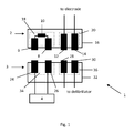
- the electrode identification system 1 comprises an electrode plug 2, a defibrillator socket 3 and an electrode identification unit 4.
- the electrode plug 2 comprises a first pair of conducting contacts in the form of pins, 6, 8, an identification element in the form of a resistive identification element 10, a second pair of conducting contacts in the form of pins, 12, 14, a housing 16 having separate first and second cavity portions 18, 20 and an aperture (not shown).
- the housing is substantially rigid and is made of non conductive plastic.
- the first pair of conducting pins, 6, 8 and the resistive identification element 10 are moulded into the housing providing the first cavity portion 18.
- the second pair of conducting pins, 12, 14 are moulded into the housing providing the second cavity portion 20.
- the first and second cavity portions 18, 20 are separate from each other and hence the first pair of conducting pins, 6, 8 and the resistive identification element 10 are electrically separated from the second pair of conducting pins, 12, 14.
- the resistive identification element 10 is connected between first ends of the first pair of conducting pins, 6, 8.
- An electrode (not shown) is connected between first ends of the second pair of conducting pins, 12, 14. Second ends of the first pair of conducting pins, 6, 8 and the second pair of conducting pins, 12, 14 extend through the aperture of the housing 16.
- the electrode connected between first ends of the second pair of conducting pins, 12, 14 is a category of electrode for use with children.
- This category of electrode is associated with an identification characteristic of the resistive identification element 10 comprising a value of the resistance of the resistive identification element 10.
- the value of the resistance is 10k ⁇ .
- the electrode connected between first ends of the second pair of conducting pins, 12, 14 could have a different category and a different associated identification characteristic of the identification element or a different associated value or range of values of the identification characteristic of the identification element of the electrode plug of the electrode.
- the important aspect is that the identification element presents a different identification characteristic or different identification characteristic value or range of values for each category of the possible different electrodes connectable to the defibrillator.
- the defibrillator socket 3 comprises a first pair of conducting contacts in the form of pins, 24, 26, a second pair of conducting contacts in the form of pins, 28, 30, a housing 32 having separate first and second cavity portions 34, 36 and an aperture (not shown).
- the housing 32 is again substantially rigid and is made of non conductive plastic.
- the first pair of conducting pins, 24, 26 are moulded into the housing 32 providing the first cavity portion 34.
- the second pair of conducting pins, 28, 30 are moulded into the housing 32 providing the second cavity portion 36.
- the first and second cavity portions 34, 36 are separate from each other and hence the first pair of conducting pins, 24, 26 is electrically separated from the second pair of conducting pins, 28, 30.
- First ends of the first pair of conducting pins, 24, 26 and the second pair of conducting pins, 28, 30 extend through the aperture of the housing 32.
- the electrode identification unit 4 is connected between second ends of the first pair of conducting pins, 24, 26. Second ends of the second pair of conducting pins, 28, 30 are connected to a defibrillator (not shown), by, in this embodiment, the defibrillator socket 3 being provided as an integral part of the defibrillator.
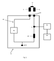
- the electrode identification unit 4 comprises a circuit 40, a signal detector 42 connected to the circuit 40, and a processor 44 connected to the signal detector 42.
- the circuit 40 is a voltage divider circuit comprising a DC voltage generator 46, a resistive electrical impedance element 48 having a resistance of 10k ⁇ , and contacts 50.
- the contacts 50 connect to the first pair of conducting pins 6, 8 and the resistive identification element 10 of the electrode plug 2, via the first pair of conducting pins of the defibrillator socket (not shown).
- the arrangement of the circuit 40 and the resistive identification element 10 of the electrode plug is such that the voltage of the DC voltage generator 46 is divided between the resistive identification element 10 of the electrode plug 2 and the resistive electrical impedance element 48 of the voltage divider circuit 40.
- the electrode plug 2 is connected with the defibrillator socket 3, such that second ends of the first pair of conducting pins, 6, 8, of the electrode plug 2 make electrical contact with first ends of the first pair of conducting pins, 24, 26, of the defibrillator socket 3. Second ends of the second pair of conducting pins, 12, 14, of the electrode plug 2 also make electrical contact with first ends of the second pair of conducting pins, 28, 30, of the defibrillator socket 3.
- a circuit is formed between pin 24 of the defibrillator socket 3, pin 6, resistive identification element 10 and pin 8 of the electrode plug 2 and pin 26 of the defibrillator socket 3.
- Pins 24, 26 of the defibrillator socket 3 are connected to contacts 50 of the voltage divider circuit 40 of the electrode identification unit 4.
- the DC voltage generator 46 of the circuit 40 is operated and a signal is caused to flow around the circuit 40 and through the resistive identification element 10 of the electrode plug 2.
- the signal detector 42 detects the signal at point A of the circuit 40.
- the signal, or a measure of the signal is passed to the processor 44, connected to the signal detector 42.
- the processor 44 uses the received signal along with the known voltage generated by the voltage generator 46 and the known resistance of the resistive electrical impedance element 48 of the voltage divider circuit 40 to determine the resistance of the resistive identification element 10 of the electrode plug 2, and to therefore identify the category of the electrode connected to the electrode plug 2 as a category of electrode for use with a child.
- the defibrillator is then able to generate and send appropriate child defibrillation signals via pins 28, 30 of the defibrillator socket 3 and pins 12, 14 of the electrode plug 2 to the electrode.
- the identification element of the electrode plug may comprise any of a resistive identification element, a capacitive identification element, an inductive identification element.
- the electrical impedance element of the voltage divider circuit may comprise a resistive electrical impedance element and the voltage generator of the voltage divider circuit may comprise a DC voltage generator.
- the electrical impedance element of the voltage divider circuit may comprise a capacitive electrical impedance element and the voltage generator of the voltage divider circuit may comprise an AC voltage generator.
- the electrical impedance element of the voltage divider circuit may comprise an inductive electrical impedance element and the voltage generator of the voltage divider circuit may comprise an AC voltage generator.
Landscapes
- Health & Medical Sciences (AREA)
- Radiology & Medical Imaging (AREA)
- Engineering & Computer Science (AREA)
- Biomedical Technology (AREA)
- Nuclear Medicine, Radiotherapy & Molecular Imaging (AREA)
- Life Sciences & Earth Sciences (AREA)
- Animal Behavior & Ethology (AREA)
- General Health & Medical Sciences (AREA)
- Public Health (AREA)
- Veterinary Medicine (AREA)
- Heart & Thoracic Surgery (AREA)
- Cardiology (AREA)
- Electrotherapy Devices (AREA)
Abstract
Description
- The invention relates to identification systems for defibrillator electrodes.
- Portable defibrillators, such as those for use in public areas, on aircraft etc., comprise two main parts - a housing enclosing defibrillation generation and control circuitry etc. and electrodes for application to a subject to provide defibrillation pulses measure ECG signals, etc. The electrodes are designed to be separable from the defibrillator housing and to be connected thereto by electrode wires and an electrode plug. It is necessary to provide different categories of electrodes having different properties for a defibrillator, for example electrodes that are suitable for delivering defibrillation signals to adults, electrodes that are suitable for delivering defibrillation signals to children, electrodes that are used for measuring ECG signals, electrodes having a required size, shape, etc. It is critical that in each of various different circumstances of use of a defibrillator, electrodes from an appropriate category having the correct properties are used. It is therefore preferable to provide a mechanism for identifying the category of electrodes connected to the defibrillator.
- According to the present invention there is provided an electrode identification system for defibrillators, comprising:
- an electrode plug adapted for connection to at least one electrode having:
- a first pair of conducting contacts,
- an identification element connected between the first pair of conducting contacts,
- a second pair of conducting contacts for connection to the electrode, and
- a housing providing a cavity which substantially encases the first and second pairs of conducting contacts and the identification element and an aperture through which ends of the first and second pairs of conducting contacts extend,
- a defibrillator socket adapted for connection to a defibrillator and adapted for connection to the electrode plug having:
- a first pair of conducting contacts for connection to the first pair of conducting contacts of the electrode plug,
- a second pair of conducting contacts for connection to the second pair of conducting contacts of the electrode plug and for connection to the defibrillator, and
- a housing providing a cavity which substantially encases the first and second pairs of conducting contacts and an aperture through which ends of the first and second pairs of conducting contacts extend, and
- an electrode identification unit adapted for connection to the defibrillator socket having:
- a circuit comprising contacts for connection to the first pair of conducting contacts of the electrode plug via the first pair of conducting contacts of the defibrillator socket,
- a signal detector connected to the circuit which detects a signal from the identification element of the electrode plug, and
- a processor which uses a measure of the signal to determine an identification characteristic of the identification element of the electrode plug and from this identifies a category of the electrode connected to the electrode plug.
- The defibrillator plug may be adapted for connection to a plurality of different categories of electrodes. The different categories of the different electrodes may each be associated with a different value or a different range of values of identification characteristic of the identification elements of the electrode plugs connected to the electrodes. The different values or ranges of values of identification characteristics of the identification elements of the different electrode plugs may have separations which are greater than a measurement accuracy of the electrode identification unit. The categories of the electrodes may comprise any of a category of electrode for use with a child, a category of electrode for use with an adult, a category of electrode for measuring an ECG signal and not for delivering defibrillation signals, a category of size of the electrode, a category of shape of the electrode, a category of manufacture date of the electrode, a category of lot number of the electrode, a category of construction of the electrode, for example a gel electrode.
- The identification element may comprise a resistive identification element. The identification characteristic of the resistive identification element may comprise a value or a range of values of resistance of the resistive identification element. The identification element may comprise a capacitive identification element. The identification characteristic of the capacitive identification element may comprise a value or a range of values of capacitance of the capacitive identification element. The identification element may comprise an inductive identification element. The identification characteristic of the inductive identification element may comprise a value or a range of values of inductance of the inductive identification element.
- The electrode plug may be connected to at least one electrode in the course of manufacture of the electrode. Thus appropriate electrode plugs and electrodes may be used together.
- The first and second pairs of conducting contacts of the electrode plug may comprise pins and may be elongate and may comprise a conductive element, such as any of copper, gold, nickel, tin or any combination thereof.
- The housing of the electrode plug may be substantially rigid and may be comprised of a non conductive plastic material, such as any of ABS, polycarbonate, compressed polystyrene or any combination thereof. The housing of the electrode plug may be provided with a location device which attaches to the defibrillator socket such that the first pair of conducting contacts of the electrode plug connect with the first pair of conducting contacts of the defibrillator socket, and the second pair of conducting contacts of the electrode plug connect with the second pair of conducting contacts of the defibrillator socket.
- The housing of the electrode plug may provide a cavity divided into separate first and second portions. The first portion may substantially encase the first pair of conducting contacts and the identification element and the second portion may substantially encase the second pair of conducting contacts to electrically insulate the first pair of conducting contacts and the identification element from the second pair of conducting contacts. The first pair of conducting contacts and the identification element may be moulded or otherwise inserted into the housing providing the first portion of the cavity. The second pair of conducting contacts may be moulded or otherwise inserted into the housing providing the second portion of the cavity.
- The defibrillator socket may be connected to a defibrillator by being provided as an integral part of the defibrillator. The defibrillator socket may be removably connected to a defibrillator via a socket receiver provided on the defibrillator.
- The first and second pair of conducting contacts of the defibrillator socket may comprise pins and may be elongate and may comprise a conductive element, such as any of copper, gold, nickel, tin or any combination thereof.
- The first pair of conducting contacts of the defibrillator socket may be connected to the first pair of conducting contacts of the electrode plug by contact between the pairs of contacts. The second pair of conducting contacts of the defibrillator socket may be connected to the second pair of conducting contacts of the electrode plug by contact between the pairs of contacts.
- The housing of the defibrillator socket may be substantially rigid and may be comprised of a non conductive plastic material, such as any of ABS, polycarbonate, compressed polystyrene or any combination thereof. The housing of the defibrillator socket may be provided with a location device which attaches to the electrode plug such that the first pair of conducting contacts of the electrode plug connect with the first pair of conducting contacts of the defibrillator socket, and the second pair of conducting contacts of the electrode plug connect with the second pair of conducting contacts of the defibrillator socket.
- The housing of the defibrillator socket may provide a cavity divided into separate first and second portions. The first portion may substantially encase the first pair of conducting contacts and the second portion may substantially encase the second pair of conducting contacts to electrically insulate the first and second pairs of conducting contacts from each other. The first pair of conducting contacts may be moulded or otherwise inserted into the housing providing the first portion of the cavity. The second pair of conducting contacts may be moulded or otherwise inserted into the housing providing the second portion of the cavity.
- The circuit of the electrode identification unit may comprise a voltage divider circuit. The voltage divider circuit may comprise a voltage generator and an electrical impedance element. The voltage divider circuit may be connected to the first pair of conducting contacts of the electrode plug via the first pair of conducting contacts of the defibrillator socket in an arrangement which divides the voltage of the voltage generator between the identification element of the electrode plug and the electrical impedance element of the voltage divider circuit. The signal detector may be connected to the voltage divider circuit to detect a signal in the circuit. The processor may use the signal or a measure of the signal to determine the identification characteristic of the identification element of the electrode plug and from this identify the category of the electrode connected to the electrode plug.
- An embodiment of the invention will now be described by way of example only, with reference to the accompanying drawings, in which:
-
Figure 1 is a schematic representation of an electrode identification system for use with an electrode suitable for children, and -
Figure 2 is a schematic representation of an electrode identification unit for use with the electrode identification system ofFigure 1 . - Referring to
Figure 1 , theelectrode identification system 1 comprises anelectrode plug 2, adefibrillator socket 3 and anelectrode identification unit 4. - The
electrode plug 2 comprises a first pair of conducting contacts in the form of pins, 6, 8, an identification element in the form of aresistive identification element 10, a second pair of conducting contacts in the form of pins, 12, 14, ahousing 16 having separate first andsecond cavity portions resistive identification element 10 are moulded into the housing providing thefirst cavity portion 18. The second pair of conducting pins, 12, 14 are moulded into the housing providing thesecond cavity portion 20. The first andsecond cavity portions resistive identification element 10 are electrically separated from the second pair of conducting pins, 12, 14. Theresistive identification element 10 is connected between first ends of the first pair of conducting pins, 6, 8. An electrode (not shown) is connected between first ends of the second pair of conducting pins, 12, 14. Second ends of the first pair of conducting pins, 6, 8 and the second pair of conducting pins, 12, 14 extend through the aperture of thehousing 16. - In this embodiment, the electrode connected between first ends of the second pair of conducting pins, 12, 14 is a category of electrode for use with children. This category of electrode is associated with an identification characteristic of the
resistive identification element 10 comprising a value of the resistance of theresistive identification element 10. In this embodiment, the value of the resistance is 10kΩ. It will be appreciated that in another embodiment, the electrode connected between first ends of the second pair of conducting pins, 12, 14 could have a different category and a different associated identification characteristic of the identification element or a different associated value or range of values of the identification characteristic of the identification element of the electrode plug of the electrode. The important aspect is that the identification element presents a different identification characteristic or different identification characteristic value or range of values for each category of the possible different electrodes connectable to the defibrillator. - The
defibrillator socket 3 comprises a first pair of conducting contacts in the form of pins, 24, 26, a second pair of conducting contacts in the form of pins, 28, 30, ahousing 32 having separate first andsecond cavity portions housing 32 is again substantially rigid and is made of non conductive plastic. The first pair of conducting pins, 24, 26 are moulded into thehousing 32 providing thefirst cavity portion 34. The second pair of conducting pins, 28, 30 are moulded into thehousing 32 providing thesecond cavity portion 36. The first andsecond cavity portions housing 32. - The
electrode identification unit 4 is connected between second ends of the first pair of conducting pins, 24, 26. Second ends of the second pair of conducting pins, 28, 30 are connected to a defibrillator (not shown), by, in this embodiment, thedefibrillator socket 3 being provided as an integral part of the defibrillator. - Referring to
Figure 2 , theelectrode identification unit 4 comprises acircuit 40, asignal detector 42 connected to thecircuit 40, and aprocessor 44 connected to thesignal detector 42. Thecircuit 40 is a voltage divider circuit comprising aDC voltage generator 46, a resistiveelectrical impedance element 48 having a resistance of 10kΩ, andcontacts 50. Thecontacts 50 connect to the first pair of conductingpins resistive identification element 10 of theelectrode plug 2, via the first pair of conducting pins of the defibrillator socket (not shown). The arrangement of thecircuit 40 and theresistive identification element 10 of the electrode plug is such that the voltage of theDC voltage generator 46 is divided between theresistive identification element 10 of theelectrode plug 2 and the resistiveelectrical impedance element 48 of thevoltage divider circuit 40. - In use of the
electrode identification system 1, theelectrode plug 2 is connected with thedefibrillator socket 3, such that second ends of the first pair of conducting pins, 6, 8, of theelectrode plug 2 make electrical contact with first ends of the first pair of conducting pins, 24, 26, of thedefibrillator socket 3. Second ends of the second pair of conducting pins, 12, 14, of theelectrode plug 2 also make electrical contact with first ends of the second pair of conducting pins, 28, 30, of thedefibrillator socket 3. A circuit is formed betweenpin 24 of thedefibrillator socket 3,pin 6,resistive identification element 10 andpin 8 of theelectrode plug 2 and pin 26 of thedefibrillator socket 3.Pins defibrillator socket 3 are connected tocontacts 50 of thevoltage divider circuit 40 of theelectrode identification unit 4. TheDC voltage generator 46 of thecircuit 40 is operated and a signal is caused to flow around thecircuit 40 and through theresistive identification element 10 of theelectrode plug 2. Thesignal detector 42 detects the signal at point A of thecircuit 40. The signal, or a measure of the signal, is passed to theprocessor 44, connected to thesignal detector 42. Theprocessor 44 uses the received signal along with the known voltage generated by thevoltage generator 46 and the known resistance of the resistiveelectrical impedance element 48 of thevoltage divider circuit 40 to determine the resistance of theresistive identification element 10 of theelectrode plug 2, and to therefore identify the category of the electrode connected to theelectrode plug 2 as a category of electrode for use with a child. The defibrillator is then able to generate and send appropriate child defibrillation signals viapins defibrillator socket 3 and pins 12, 14 of theelectrode plug 2 to the electrode. - It will be appreciated that the identification element of the electrode plug may comprise any of a resistive identification element, a capacitive identification element, an inductive identification element. When the identification element of the electrode plug comprises a resistive identification element, the electrical impedance element of the voltage divider circuit may comprise a resistive electrical impedance element and the voltage generator of the voltage divider circuit may comprise a DC voltage generator. When the identification element of the electrode plug comprises a capacitive identification element, the electrical impedance element of the voltage divider circuit may comprise a capacitive electrical impedance element and the voltage generator of the voltage divider circuit may comprise an AC voltage generator. When the identification element of the electrode plug comprises an inductive identification element, the electrical impedance element of the voltage divider circuit may comprise an inductive electrical impedance element and the voltage generator of the voltage divider circuit may comprise an AC voltage generator.
Claims (16)
- An electrode identification system (1) for defibrillators, comprising:an electrode plug (2) adapted for connection to at least one electrode having:a first pair of conducting contacts (6, 8),an identification element (10) connected between the first pair of conducting contacts (6, 8),a second pair of conducting contacts (12, 14) for connection to the electrode, anda housing (16) providing a cavity (18, 20) which substantially encases the first and second pairs of conducting contacts (6, 8, 12, 14) and the identification element (10) and an aperture through which ends of the first and second pairs of conducting contacts extend,a defibrillator socket (3) adapted for connection to a defibrillator and adapted for connection to the electrode plug (2) having:a first pair of conducting contacts (24, 26) for connection to the first pair of conducting contacts (6, 8) of the electrode plug (2),a second pair of conducting contacts (28, 30) for connection to the second pair of conducting contacts (12, 14) of the electrode plug (2) and for connection to the defibrillator, anda housing (32) providing a cavity (34, 36) which substantially encases the first and second pairs of conducting contacts (24, 26, 28, 30) and an aperture through which ends of the first and second pairs of conducting contacts extend, andan electrode identification unit (4) adapted for connection to the defibrillator socket (3) having:a circuit (40) comprising contacts (50) for connection to the first pair of conducting contacts (6, 8) of the electrode plug (2) via the first pair of conducting contacts (24, 26) of the defibrillator socket (3),a signal detector (42) connected to the circuit (40) which detects a signal from the identification element (10) of the electrode plug (2), anda processor (44) which uses a measure of the signal to determine an identification characteristic of the identification element (10) of the electrode plug (2) and from this identifies a category of the electrode connected to the electrode plug.
- A system according to claim 1 in which the defibrillator plug (3) is adapted for connection to a plurality of different categories of electrodes and the different categories of the different electrodes are each associated with a different identification characteristic or a different value or a different range of values of identification characteristic of the identification elements (10) of the electrode plugs (2) connected to the electrodes.
- A system according to claim 2 in which the different values or ranges of values of identification characteristic of the identification elements (10) of the different electrodes have separations which are greater than a measurement accuracy of the electrode identification unit (4).
- A system according to any of claims 1 to 3 in which the categories of the electrodes may comprise any of a category of electrode for use with a child, a category of electrode for use with an adult, a category of electrode for measuring an ECG signal and not for delivering defibrillation signals, a category of size of the electrode, a category of shape of the electrode, a category of manufacture date of the electrode, a category of lot number of the electrode, a category of construction of the electrode.
- A system according to any of claims 1 to 4 in which the identification element (10) comprises a resistive identification element and the identification characteristic of the resistive identification element comprises a value or a range of values of resistance of the resistive identification element.
- A system according to any of claims 1 to 4 in which the identification element (10) comprises a capacitive identification element and the identification characteristic of the capacitive identification element comprises a value or a range of values of capacitance of the capacitive identification element.
- A system according to any of claims 1 to 4 in which the identification element (10) comprises an inductive identification element and the identification characteristic of the inductive identification element comprises a value or a range of values of inductance of the inductive identification element.
- A system according to any preceding claim in which the housing (16) of the electrode plug (2) is substantially rigid and comprised of a non conductive plastic material, such as any of ABS, polycarbonate, compressed polystyrene or any combination thereof.
- A system according to any preceding claim in which the housing (16) of the electrode plug (2) provides a cavity divided into separate first and second portions (18, 20) and the first portion (18) substantially encases the first pair of conducting contacts (6, 8) and the identification element (10) and the second portion (20) substantially encases the second pair of conducting contacts (12, 14), to electrically insulate the first pair of conducting contacts and the identification element from the second pair of conducting contacts.
- A system according to claim 9 in which the first pair of conducting contacts (6, 8) and the identification element (10) are moulded into the housing providing the first portion (18) of the cavity and the second pair of conducting contacts (12, 14) are moulded into the housing providing the second portion (20) of the cavity.
- A system according to any preceding claim in which the housing (32) of the defibrillator socket (3) is substantially rigid and comprised of a non conductive plastic material, such as any of ABS, polycarbonate, compressed polystyrene or any combination thereof.
- A system according to any preceding claim in which the housing (32) of the defibrillator socket (3) provides a cavity divided into separate first and second portions (34, 36) and the first portion (34) substantially encases the first pair of conducting contacts (24, 26) and the second portion (36) substantially encases the second pair of conducting contacts (28, 30) to electrically insulate the first and second pairs of conducting contacts from each other.
- A system according to claim 12 in which the first pair of conducting contacts (24, 26) are moulded into the housing providing the first portion (34) of the cavity and the second pair of conducting contacts (28, 30) are moulded into the housing providing the second portion (36) of the cavity.
- A system according to any preceding claim in which the circuit (40) of the electrode identification unit (4) comprises a voltage divider circuit comprising a voltage generator (46) and an electrical impedance element (48).
- A system according to claim 14 in which the voltage divider circuit (40) is connected to the first pair of conducting pins (6, 8) of the electrode plug (2) via the first pair of conducting contacts (24, 26) of the defibrillator socket (3) in an arrangement which divides the voltage of the voltage generator (46) between the identification element (10) of the electrode plug (2) and the electrical impedance element (48) of the voltage divider circuit (40).
- A system according to claim 14 or claim 15 in which the signal detector (42) is connected to the voltage divider circuit (40) to detect a signal in the circuit and the processor (44) uses the signal or a measure of the signal to determine the identification characteristic of the identification element (10) of the electrode plug (2) and identify the category of the electrode connected to the electrode plug.
Applications Claiming Priority (1)
| Application Number | Priority Date | Filing Date | Title |
|---|---|---|---|
| GB1302625.7A GB2510850B (en) | 2013-02-14 | 2013-02-14 | Defibrillator electrode identification system |
Publications (2)
| Publication Number | Publication Date |
|---|---|
| EP2767309A1 true EP2767309A1 (en) | 2014-08-20 |
| EP2767309B1 EP2767309B1 (en) | 2022-12-28 |
Family
ID=48048412
Family Applications (1)
| Application Number | Title | Priority Date | Filing Date |
|---|---|---|---|
| EP14154810.7A Active EP2767309B1 (en) | 2013-02-14 | 2014-02-12 | Defibrillator electrode identification system |
Country Status (5)
| Country | Link |
|---|---|
| US (2) | US9675810B2 (en) |
| EP (1) | EP2767309B1 (en) |
| JP (1) | JP6162054B2 (en) |
| AU (1) | AU2014200727B2 (en) |
| GB (1) | GB2510850B (en) |
Families Citing this family (3)
| Publication number | Priority date | Publication date | Assignee | Title |
|---|---|---|---|---|
| US11331471B2 (en) | 2018-09-26 | 2022-05-17 | Avive Solutions, Inc. | Electrode pad cartridge for defibrillators |
| US12194305B2 (en) | 2018-09-26 | 2025-01-14 | Avive Solutions, Inc. | Electrode pad cartridge for defibrillators |
| CN112714664B (en) * | 2019-02-27 | 2024-06-11 | 深圳迈瑞生物医疗电子股份有限公司 | Defibrillator and electrodes |
Citations (3)
| Publication number | Priority date | Publication date | Assignee | Title |
|---|---|---|---|---|
| US5441520A (en) * | 1993-04-06 | 1995-08-15 | Hewlett-Packard Corporation | Defibrillator patient connection system with automatic identification |
| WO2005030327A1 (en) * | 2003-09-30 | 2005-04-07 | Koninklijke Philips Electronics, N.V. | Identification system for defibrillator electrode package |
| US20080027338A1 (en) * | 2006-02-28 | 2008-01-31 | Lu Zhong Q | Electrocardiogram Monitoring |
Family Cites Families (13)
| Publication number | Priority date | Publication date | Assignee | Title |
|---|---|---|---|---|
| US4695107A (en) * | 1986-06-09 | 1987-09-22 | Leppert James B | Integrated circuit sockets |
| JPH0451810Y2 (en) * | 1987-01-27 | 1992-12-07 | ||
| US6101413A (en) * | 1996-06-04 | 2000-08-08 | Survivalink Corporation | Circuit detectable pediatric defibrillation electrodes |
| JP2001046518A (en) * | 1999-08-09 | 2001-02-20 | Ito Choutanpa Kk | Ultrashort wave treatment device |
| US6560485B2 (en) * | 2001-03-27 | 2003-05-06 | Koninklijke Philips Electronics N.V. | Four contact identification defibrillator electrode system |
| CN1918611A (en) * | 2004-02-10 | 2007-02-21 | 皇家飞利浦电子股份有限公司 | External defibrillator training apparatus and method |
| CN101084040B (en) * | 2004-12-20 | 2012-12-05 | 皇家飞利浦电子股份有限公司 | Automatic external defibrillator for adult and pediatric patients |
| WO2006102420A2 (en) * | 2005-03-21 | 2006-09-28 | Defibtech, Llc | Pcb blade connector system and method |
| JP2006296457A (en) * | 2005-04-15 | 2006-11-02 | Omron Healthcare Co Ltd | Low-frequency therapy apparatus |
| US20090065565A1 (en) * | 2007-09-12 | 2009-03-12 | Vascular Technologies, Inc. | System, method and apparatus for preventing reuse of medical instruments |
| EP2227843B1 (en) * | 2007-10-12 | 2019-03-06 | Masimo Corporation | Connector assembly |
| JP5196311B2 (en) * | 2008-09-12 | 2013-05-15 | 日本光電工業株式会社 | Disposable electrode and automatic expiration date recognition device thereof |
| JP5317179B2 (en) * | 2008-10-21 | 2013-10-16 | ミナト医科学株式会社 | Electrostimulator with electrode identification function |
-
2013
- 2013-02-14 GB GB1302625.7A patent/GB2510850B/en active Active
-
2014
- 2014-02-11 AU AU2014200727A patent/AU2014200727B2/en active Active
- 2014-02-12 US US14/179,125 patent/US9675810B2/en active Active
- 2014-02-12 JP JP2014024594A patent/JP6162054B2/en active Active
- 2014-02-12 EP EP14154810.7A patent/EP2767309B1/en active Active
-
2017
- 2017-06-12 US US15/620,507 patent/US20170340892A1/en not_active Abandoned
Patent Citations (3)
| Publication number | Priority date | Publication date | Assignee | Title |
|---|---|---|---|---|
| US5441520A (en) * | 1993-04-06 | 1995-08-15 | Hewlett-Packard Corporation | Defibrillator patient connection system with automatic identification |
| WO2005030327A1 (en) * | 2003-09-30 | 2005-04-07 | Koninklijke Philips Electronics, N.V. | Identification system for defibrillator electrode package |
| US20080027338A1 (en) * | 2006-02-28 | 2008-01-31 | Lu Zhong Q | Electrocardiogram Monitoring |
Also Published As
| Publication number | Publication date |
|---|---|
| AU2014200727A1 (en) | 2014-08-28 |
| JP2014155793A (en) | 2014-08-28 |
| AU2014200727B2 (en) | 2016-11-24 |
| GB201302625D0 (en) | 2013-04-03 |
| US20140228903A1 (en) | 2014-08-14 |
| EP2767309B1 (en) | 2022-12-28 |
| JP6162054B2 (en) | 2017-07-12 |
| GB2510850A (en) | 2014-08-20 |
| US20170340892A1 (en) | 2017-11-30 |
| GB2510850B (en) | 2017-06-07 |
| US9675810B2 (en) | 2017-06-13 |
Similar Documents
| Publication | Publication Date | Title |
|---|---|---|
| EP3406297B1 (en) | Testing of defibrillator electrodes | |
| US10088500B2 (en) | Combination test device | |
| US20170340892A1 (en) | Defibrillator Electrode Identification System | |
| CN103543422B (en) | For determining method and the conductivity sensor of at least one fault of conductive conductivity sensor | |
| JP5830012B2 (en) | Electrode assembly | |
| US20080311796A1 (en) | Four-wire ohmmeter connector and ohmmeter using same | |
| CN106108902B (en) | Physique balance | |
| CN109195660B (en) | Examination device for testing at least one first medical electrode | |
| US9880218B2 (en) | Test electrode for argon plasma coagulation medical instrument | |
| US20160262644A1 (en) | Production of electrical contact with skin | |
| US11307224B2 (en) | Measuring rod for electric meter and electric meter assembly using the same | |
| US7212392B2 (en) | Personal body grounding system instrumentation and process | |
| EP3535846B1 (en) | Living body detection method and apparatus | |
| JP4641988B2 (en) | Voltage detector | |
| CN117562527A (en) | Bioimpedance detection circuit, contact state detection method, chip and electronic equipment | |
| CN213423442U (en) | Socket detection circuit and socket detection device | |
| CN104459381B (en) | Safety error prevention device for full-electronic fuse testing and use method of safety error prevention device | |
| CN101668477A (en) | Disposable sensor device and monitoring system | |
| KR20160118742A (en) | Human potential measuring device | |
| CN206990710U (en) | Failure detector and cooking apparatus are installed | |
| JP3409140B2 (en) | Automatic sensitivity detector | |
| CN217639260U (en) | Test pencil | |
| CN217332596U (en) | System and electronic device for detecting residual voltage of electrical consumer | |
| CN109428577A (en) | For capacitively detecting the sensor device of user's operation in the car | |
| CN219694389U (en) | Food probe |
Legal Events
| Date | Code | Title | Description |
|---|---|---|---|
| PUAI | Public reference made under article 153(3) epc to a published international application that has entered the european phase |
Free format text: ORIGINAL CODE: 0009012 |
|
| 17P | Request for examination filed |
Effective date: 20140212 |
|
| AK | Designated contracting states |
Kind code of ref document: A1 Designated state(s): AL AT BE BG CH CY CZ DE DK EE ES FI FR GB GR HR HU IE IS IT LI LT LU LV MC MK MT NL NO PL PT RO RS SE SI SK SM TR |
|
| AX | Request for extension of the european patent |
Extension state: BA ME |
|
| R17P | Request for examination filed (corrected) |
Effective date: 20150320 |
|
| RBV | Designated contracting states (corrected) |
Designated state(s): AL AT BE BG CH CY CZ DE DK EE ES FI FR GB GR HR HU IE IS IT LI LT LU LV MC MK MT NL NO PL PT RO RS SE SI SK SM TR |
|
| STAA | Information on the status of an ep patent application or granted ep patent |
Free format text: STATUS: EXAMINATION IS IN PROGRESS |
|
| 17Q | First examination report despatched |
Effective date: 20171109 |
|
| GRAP | Despatch of communication of intention to grant a patent |
Free format text: ORIGINAL CODE: EPIDOSNIGR1 |
|
| STAA | Information on the status of an ep patent application or granted ep patent |
Free format text: STATUS: GRANT OF PATENT IS INTENDED |
|
| INTG | Intention to grant announced |
Effective date: 20220125 |
|
| RAP3 | Party data changed (applicant data changed or rights of an application transferred) |
Owner name: HEARTSINE TECHNOLOGIES LIMITED |
|
| GRAJ | Information related to disapproval of communication of intention to grant by the applicant or resumption of examination proceedings by the epo deleted |
Free format text: ORIGINAL CODE: EPIDOSDIGR1 |
|
| STAA | Information on the status of an ep patent application or granted ep patent |
Free format text: STATUS: EXAMINATION IS IN PROGRESS |
|
| INTC | Intention to grant announced (deleted) | ||
| GRAJ | Information related to disapproval of communication of intention to grant by the applicant or resumption of examination proceedings by the epo deleted |
Free format text: ORIGINAL CODE: EPIDOSDIGR1 |
|
| GRAP | Despatch of communication of intention to grant a patent |
Free format text: ORIGINAL CODE: EPIDOSNIGR1 |
|
| INTG | Intention to grant announced |
Effective date: 20220707 |
|
| INTC | Intention to grant announced (deleted) | ||
| GRAP | Despatch of communication of intention to grant a patent |
Free format text: ORIGINAL CODE: EPIDOSNIGR1 |
|
| STAA | Information on the status of an ep patent application or granted ep patent |
Free format text: STATUS: GRANT OF PATENT IS INTENDED |
|
| INTG | Intention to grant announced |
Effective date: 20220909 |
|
| GRAS | Grant fee paid |
Free format text: ORIGINAL CODE: EPIDOSNIGR3 |
|
| GRAA | (expected) grant |
Free format text: ORIGINAL CODE: 0009210 |
|
| STAA | Information on the status of an ep patent application or granted ep patent |
Free format text: STATUS: THE PATENT HAS BEEN GRANTED |
|
| AK | Designated contracting states |
Kind code of ref document: B1 Designated state(s): AL AT BE BG CH CY CZ DE DK EE ES FI FR GB GR HR HU IE IS IT LI LT LU LV MC MK MT NL NO PL PT RO RS SE SI SK SM TR |
|
| REG | Reference to a national code |
Ref country code: GB Ref legal event code: FG4D |
|
| REG | Reference to a national code |
Ref country code: CH Ref legal event code: EP |
|
| REG | Reference to a national code |
Ref country code: DE Ref legal event code: R096 Ref document number: 602014085911 Country of ref document: DE |
|
| REG | Reference to a national code |
Ref country code: AT Ref legal event code: REF Ref document number: 1540082 Country of ref document: AT Kind code of ref document: T Effective date: 20230115 |
|
| REG | Reference to a national code |
Ref country code: IE Ref legal event code: FG4D |
|
| REG | Reference to a national code |
Ref country code: NL Ref legal event code: FP |
|
| REG | Reference to a national code |
Ref country code: LT Ref legal event code: MG9D |
|
| PG25 | Lapsed in a contracting state [announced via postgrant information from national office to epo] |
Ref country code: SE Free format text: LAPSE BECAUSE OF FAILURE TO SUBMIT A TRANSLATION OF THE DESCRIPTION OR TO PAY THE FEE WITHIN THE PRESCRIBED TIME-LIMIT Effective date: 20221228 Ref country code: NO Free format text: LAPSE BECAUSE OF FAILURE TO SUBMIT A TRANSLATION OF THE DESCRIPTION OR TO PAY THE FEE WITHIN THE PRESCRIBED TIME-LIMIT Effective date: 20230328 Ref country code: LT Free format text: LAPSE BECAUSE OF FAILURE TO SUBMIT A TRANSLATION OF THE DESCRIPTION OR TO PAY THE FEE WITHIN THE PRESCRIBED TIME-LIMIT Effective date: 20221228 Ref country code: FI Free format text: LAPSE BECAUSE OF FAILURE TO SUBMIT A TRANSLATION OF THE DESCRIPTION OR TO PAY THE FEE WITHIN THE PRESCRIBED TIME-LIMIT Effective date: 20221228 |
|
| REG | Reference to a national code |
Ref country code: AT Ref legal event code: MK05 Ref document number: 1540082 Country of ref document: AT Kind code of ref document: T Effective date: 20221228 |
|
| PG25 | Lapsed in a contracting state [announced via postgrant information from national office to epo] |
Ref country code: RS Free format text: LAPSE BECAUSE OF FAILURE TO SUBMIT A TRANSLATION OF THE DESCRIPTION OR TO PAY THE FEE WITHIN THE PRESCRIBED TIME-LIMIT Effective date: 20221228 Ref country code: LV Free format text: LAPSE BECAUSE OF FAILURE TO SUBMIT A TRANSLATION OF THE DESCRIPTION OR TO PAY THE FEE WITHIN THE PRESCRIBED TIME-LIMIT Effective date: 20221228 Ref country code: HR Free format text: LAPSE BECAUSE OF FAILURE TO SUBMIT A TRANSLATION OF THE DESCRIPTION OR TO PAY THE FEE WITHIN THE PRESCRIBED TIME-LIMIT Effective date: 20221228 Ref country code: GR Free format text: LAPSE BECAUSE OF FAILURE TO SUBMIT A TRANSLATION OF THE DESCRIPTION OR TO PAY THE FEE WITHIN THE PRESCRIBED TIME-LIMIT Effective date: 20230329 |
|
| P01 | Opt-out of the competence of the unified patent court (upc) registered |
Effective date: 20230522 |
|
| PG25 | Lapsed in a contracting state [announced via postgrant information from national office to epo] |
Ref country code: SM Free format text: LAPSE BECAUSE OF FAILURE TO SUBMIT A TRANSLATION OF THE DESCRIPTION OR TO PAY THE FEE WITHIN THE PRESCRIBED TIME-LIMIT Effective date: 20221228 Ref country code: RO Free format text: LAPSE BECAUSE OF FAILURE TO SUBMIT A TRANSLATION OF THE DESCRIPTION OR TO PAY THE FEE WITHIN THE PRESCRIBED TIME-LIMIT Effective date: 20221228 Ref country code: PT Free format text: LAPSE BECAUSE OF FAILURE TO SUBMIT A TRANSLATION OF THE DESCRIPTION OR TO PAY THE FEE WITHIN THE PRESCRIBED TIME-LIMIT Effective date: 20230428 Ref country code: ES Free format text: LAPSE BECAUSE OF FAILURE TO SUBMIT A TRANSLATION OF THE DESCRIPTION OR TO PAY THE FEE WITHIN THE PRESCRIBED TIME-LIMIT Effective date: 20221228 Ref country code: EE Free format text: LAPSE BECAUSE OF FAILURE TO SUBMIT A TRANSLATION OF THE DESCRIPTION OR TO PAY THE FEE WITHIN THE PRESCRIBED TIME-LIMIT Effective date: 20221228 Ref country code: CZ Free format text: LAPSE BECAUSE OF FAILURE TO SUBMIT A TRANSLATION OF THE DESCRIPTION OR TO PAY THE FEE WITHIN THE PRESCRIBED TIME-LIMIT Effective date: 20221228 Ref country code: AT Free format text: LAPSE BECAUSE OF FAILURE TO SUBMIT A TRANSLATION OF THE DESCRIPTION OR TO PAY THE FEE WITHIN THE PRESCRIBED TIME-LIMIT Effective date: 20221228 |
|
| PG25 | Lapsed in a contracting state [announced via postgrant information from national office to epo] |
Ref country code: SK Free format text: LAPSE BECAUSE OF FAILURE TO SUBMIT A TRANSLATION OF THE DESCRIPTION OR TO PAY THE FEE WITHIN THE PRESCRIBED TIME-LIMIT Effective date: 20221228 Ref country code: PL Free format text: LAPSE BECAUSE OF FAILURE TO SUBMIT A TRANSLATION OF THE DESCRIPTION OR TO PAY THE FEE WITHIN THE PRESCRIBED TIME-LIMIT Effective date: 20221228 Ref country code: IS Free format text: LAPSE BECAUSE OF FAILURE TO SUBMIT A TRANSLATION OF THE DESCRIPTION OR TO PAY THE FEE WITHIN THE PRESCRIBED TIME-LIMIT Effective date: 20230428 Ref country code: AL Free format text: LAPSE BECAUSE OF FAILURE TO SUBMIT A TRANSLATION OF THE DESCRIPTION OR TO PAY THE FEE WITHIN THE PRESCRIBED TIME-LIMIT Effective date: 20221228 |
|
| PG25 | Lapsed in a contracting state [announced via postgrant information from national office to epo] |
Ref country code: MC Free format text: LAPSE BECAUSE OF FAILURE TO SUBMIT A TRANSLATION OF THE DESCRIPTION OR TO PAY THE FEE WITHIN THE PRESCRIBED TIME-LIMIT Effective date: 20221228 |
|
| REG | Reference to a national code |
Ref country code: CH Ref legal event code: PL Ref country code: DE Ref legal event code: R097 Ref document number: 602014085911 Country of ref document: DE |
|
| REG | Reference to a national code |
Ref country code: BE Ref legal event code: MM Effective date: 20230228 |
|
| PG25 | Lapsed in a contracting state [announced via postgrant information from national office to epo] |
Ref country code: LU Free format text: LAPSE BECAUSE OF NON-PAYMENT OF DUE FEES Effective date: 20230212 Ref country code: LI Free format text: LAPSE BECAUSE OF NON-PAYMENT OF DUE FEES Effective date: 20230228 Ref country code: DK Free format text: LAPSE BECAUSE OF FAILURE TO SUBMIT A TRANSLATION OF THE DESCRIPTION OR TO PAY THE FEE WITHIN THE PRESCRIBED TIME-LIMIT Effective date: 20221228 Ref country code: CH Free format text: LAPSE BECAUSE OF NON-PAYMENT OF DUE FEES Effective date: 20230228 |
|
| PLBE | No opposition filed within time limit |
Free format text: ORIGINAL CODE: 0009261 |
|
| STAA | Information on the status of an ep patent application or granted ep patent |
Free format text: STATUS: NO OPPOSITION FILED WITHIN TIME LIMIT |
|
| 26N | No opposition filed |
Effective date: 20230929 |
|
| REG | Reference to a national code |
Ref country code: IE Ref legal event code: MM4A |
|
| PG25 | Lapsed in a contracting state [announced via postgrant information from national office to epo] |
Ref country code: SI Free format text: LAPSE BECAUSE OF FAILURE TO SUBMIT A TRANSLATION OF THE DESCRIPTION OR TO PAY THE FEE WITHIN THE PRESCRIBED TIME-LIMIT Effective date: 20221228 Ref country code: IE Free format text: LAPSE BECAUSE OF NON-PAYMENT OF DUE FEES Effective date: 20230212 |
|
| REG | Reference to a national code |
Ref country code: DE Ref legal event code: R081 Ref document number: 602014085911 Country of ref document: DE Owner name: STRYKER EUROPEAN OPERATIONS LIMITED, CARRIGTWO, IE Free format text: FORMER OWNER: HEARTSINE TECHNOLOGIES LTD., BELFAST, GB |
|
| PG25 | Lapsed in a contracting state [announced via postgrant information from national office to epo] |
Ref country code: BE Free format text: LAPSE BECAUSE OF NON-PAYMENT OF DUE FEES Effective date: 20230228 |
|
| REG | Reference to a national code |
Ref country code: GB Ref legal event code: 732E Free format text: REGISTERED BETWEEN 20240229 AND 20240306 |
|
| REG | Reference to a national code |
Ref country code: NL Ref legal event code: PD Owner name: STRYKER EUROPEAN OPERATIONS LIMITED; IE Free format text: DETAILS ASSIGNMENT: CHANGE OF OWNER(S), ASSIGNMENT; FORMER OWNER NAME: HEARTSINE TECHNOLOGIES LIMITED Effective date: 20240403 |
|
| PG25 | Lapsed in a contracting state [announced via postgrant information from national office to epo] |
Ref country code: IT Free format text: LAPSE BECAUSE OF FAILURE TO SUBMIT A TRANSLATION OF THE DESCRIPTION OR TO PAY THE FEE WITHIN THE PRESCRIBED TIME-LIMIT Effective date: 20221228 |
|
| PG25 | Lapsed in a contracting state [announced via postgrant information from national office to epo] |
Ref country code: BG Free format text: LAPSE BECAUSE OF FAILURE TO SUBMIT A TRANSLATION OF THE DESCRIPTION OR TO PAY THE FEE WITHIN THE PRESCRIBED TIME-LIMIT Effective date: 20221228 |
|
| PG25 | Lapsed in a contracting state [announced via postgrant information from national office to epo] |
Ref country code: BG Free format text: LAPSE BECAUSE OF FAILURE TO SUBMIT A TRANSLATION OF THE DESCRIPTION OR TO PAY THE FEE WITHIN THE PRESCRIBED TIME-LIMIT Effective date: 20221228 |
|
| PG25 | Lapsed in a contracting state [announced via postgrant information from national office to epo] |
Ref country code: CY Free format text: LAPSE BECAUSE OF FAILURE TO SUBMIT A TRANSLATION OF THE DESCRIPTION OR TO PAY THE FEE WITHIN THE PRESCRIBED TIME-LIMIT; INVALID AB INITIO Effective date: 20140212 |
|
| PG25 | Lapsed in a contracting state [announced via postgrant information from national office to epo] |
Ref country code: HU Free format text: LAPSE BECAUSE OF FAILURE TO SUBMIT A TRANSLATION OF THE DESCRIPTION OR TO PAY THE FEE WITHIN THE PRESCRIBED TIME-LIMIT; INVALID AB INITIO Effective date: 20140212 |
|
| PG25 | Lapsed in a contracting state [announced via postgrant information from national office to epo] |
Ref country code: TR Free format text: LAPSE BECAUSE OF FAILURE TO SUBMIT A TRANSLATION OF THE DESCRIPTION OR TO PAY THE FEE WITHIN THE PRESCRIBED TIME-LIMIT Effective date: 20221228 |
|
| PGFP | Annual fee paid to national office [announced via postgrant information from national office to epo] |
Ref country code: FR Payment date: 20251208 Year of fee payment: 13 Ref country code: NL Payment date: 20251215 Year of fee payment: 13 |
|
| PGFP | Annual fee paid to national office [announced via postgrant information from national office to epo] |
Ref country code: GB Payment date: 20260106 Year of fee payment: 13 |
|
| PGFP | Annual fee paid to national office [announced via postgrant information from national office to epo] |
Ref country code: DE Payment date: 20251216 Year of fee payment: 13 |