EP2767296A1 - Diagnostic method of dialysate preparation device, and dialysate preparation device - Google Patents
Diagnostic method of dialysate preparation device, and dialysate preparation device Download PDFInfo
- Publication number
- EP2767296A1 EP2767296A1 EP20120839867 EP12839867A EP2767296A1 EP 2767296 A1 EP2767296 A1 EP 2767296A1 EP 20120839867 EP20120839867 EP 20120839867 EP 12839867 A EP12839867 A EP 12839867A EP 2767296 A1 EP2767296 A1 EP 2767296A1
- Authority
- EP
- European Patent Office
- Prior art keywords
- fluid
- passage
- dialysis
- measurement means
- concentration measurement
- Prior art date
- Legal status (The legal status is an assumption and is not a legal conclusion. Google has not performed a legal analysis and makes no representation as to the accuracy of the status listed.)
- Granted
Links
Images
Classifications
-
- A—HUMAN NECESSITIES
- A61—MEDICAL OR VETERINARY SCIENCE; HYGIENE
- A61M—DEVICES FOR INTRODUCING MEDIA INTO, OR ONTO, THE BODY; DEVICES FOR TRANSDUCING BODY MEDIA OR FOR TAKING MEDIA FROM THE BODY; DEVICES FOR PRODUCING OR ENDING SLEEP OR STUPOR
- A61M1/00—Suction or pumping devices for medical purposes; Devices for carrying-off, for treatment of, or for carrying-over, body-liquids; Drainage systems
- A61M1/14—Dialysis systems; Artificial kidneys; Blood oxygenators ; Reciprocating systems for treatment of body fluids, e.g. single needle systems for hemofiltration or pheresis
- A61M1/16—Dialysis systems; Artificial kidneys; Blood oxygenators ; Reciprocating systems for treatment of body fluids, e.g. single needle systems for hemofiltration or pheresis with membranes
- A61M1/1654—Dialysates therefor
- A61M1/1656—Apparatus for preparing dialysates
-
- A—HUMAN NECESSITIES
- A61—MEDICAL OR VETERINARY SCIENCE; HYGIENE
- A61M—DEVICES FOR INTRODUCING MEDIA INTO, OR ONTO, THE BODY; DEVICES FOR TRANSDUCING BODY MEDIA OR FOR TAKING MEDIA FROM THE BODY; DEVICES FOR PRODUCING OR ENDING SLEEP OR STUPOR
- A61M1/00—Suction or pumping devices for medical purposes; Devices for carrying-off, for treatment of, or for carrying-over, body-liquids; Drainage systems
- A61M1/14—Dialysis systems; Artificial kidneys; Blood oxygenators ; Reciprocating systems for treatment of body fluids, e.g. single needle systems for hemofiltration or pheresis
- A61M1/16—Dialysis systems; Artificial kidneys; Blood oxygenators ; Reciprocating systems for treatment of body fluids, e.g. single needle systems for hemofiltration or pheresis with membranes
- A61M1/1654—Dialysates therefor
- A61M1/1656—Apparatus for preparing dialysates
- A61M1/1657—Apparatus for preparing dialysates with centralised supply of dialysate or constituent thereof for more than one dialysis unit
Definitions
- the present invention relates to a diagnosis method for a dialysis fluid preparation apparatus and a dialysis fluid preparation apparatus, and specifically to a diagnosis method for a dialysis fluid preparation apparatus and a dialysis fluid preparation apparatus that mix purified water, an A fluid and a B fluid in predetermined proportions respectively to prepare a dialysis fluid and measure the concentration of the prepared dialysis fluid by concentration measurement means.
- a dialysis fluid preparation apparatus including a water feed passage that feeds purified water, an A fluid passage that is connected with the water feed passage and feeds an A fluid containing sodium chloride as a principal ingredient, and a B fluid passage that is connected with the water feed passage and feeds a B fluid composed of a sodium bicarbonate aqueous solution, in order to prepare a dialysis fluid to be used in a dialysis apparatus.
- Such a dialysis fluid preparation apparatus includes concentration measurement means provided with a detection unit for electric conductivity downstream of the connecting positions of the A fluid passage and the B fluid passage on the water feed passage, in order to judge whether the prepared dialysis fluid is not abnormal.
- dialysis fluid preparation apparatus there is known a dialysis fluid preparation apparatus that, before preparing the dialysis fluid, previously checks the behavior of on-off valves and the like provided therein, for safety improvement in dialysis treatment (Patent Literature 1).
- Patent Literature 1 Japanese Patent Laid-Open No. 6-142191
- the dialysis fluid preparation apparatus in Patent Literature 1 does not diagnose the accuracy of the concentration measurement means, and there is a possibility that a normal concentration measurement of the dialysis fluid is not performed and the concentration of the prepared dialysis fluid becomes unstable, in the case where the accuracy of the concentration measurement means is decreased, for example, by the adhesion of dialysis fluid deposits to electrodes constituting the detection unit.
- the present invention provides a diagnosis method for a dialysis fluid preparation apparatus and a dialysis fluid preparation apparatus that do not require special reagents, devices or the like for the diagnosis of the concentration measurement means and allow for a simple diagnosis.
- a diagnosis method for a dialysis fluid preparation apparatus is a diagnosis method for a dialysis fluid preparation apparatus that includes: a water feed passage to feed purified water; an A fluid passage to feed an A fluid containing sodium chloride as a principal ingredient, the A fluid passage being connected with the water feed passage; a B fluid passage to feed a B fluid composed of a sodium bicarbonate aqueous solution, the B fluid passage being connected with the water feed passage; and concentration measurement means provided with a detection unit downstream of connecting positions of the A fluid passage and the B fluid passage on the water feed passage, the dialysis fluid preparation apparatus mixing the purified water, the A fluid and the B fluid in predetermined proportions respectively to prepare a dialysis fluid, and measuring a concentration of the prepared dialysis fluid by the concentration measurement means, in which the diagnosis method for the dialysis fluid preparation apparatus, before preparing the dialysis fluid, feeds the B fluid from the B fluid passage to the water feed passage so as to flow only the B fluid to the water feed passage,
- a dialysis fluid preparation apparatus is a dialysis fluid preparation apparatus that includes: a water feed passage to flow purified water; a water feed pump provided on the water feed passage; an A fluid passage to feed an A fluid containing sodium chloride as a principal ingredient, the A fluid passage being connected with the water feed passage; an A fluid pump provided on the A fluid passage; a B fluid passage to feed a B fluid composed of a sodium bicarbonate aqueous solution, the B fluid passage being connected with the water feed passage; a B fluid pump provided on the B fluid passage; concentration measurement means provided with a detection unit downstream of connecting positions of the A fluid passage and the B fluid passage on the water feed passage; and control means to control actuations of the pumps, the dialysis fluid preparation apparatus mixing the purified water, the A fluid and the B fluid in predetermined proportions to prepare a dialysis fluid, in which the control means is provided with a diagnosis unit to diagnose accuracy of the concentration measurement means, the control means actuates the B fluid pump to perform a fluid sending of only
- the inventions of claim 1 and claim 4 use the B fluid to be used in the preparation of the dialysis fluid, for diagnosing the accuracy of the concentration measurement apparatus, and therefore do not require special reagents, devices or the like, allowing for a simple diagnosis within the dialysis fluid preparation apparatus including the concentration measurement apparatus.
- Figure 1 shows a dialysis fluid preparation apparatus 1 that is installed in hospitals and the like.
- This dialysis fluid preparation apparatus 1 feeds a prepared dialysis fluid to a plurality of dialysis monitoring apparatuses not shown in the figure, as a so-called dialysis fluid feed apparatus for many persons.
- the dialysis fluid preparation apparatus 1 includes a water feed passage 2 that is connected with purified water feed means to feed purified water, which is not shown in the figure, an A fluid passage 3 that is connected with the water feed passage 2 and feeds an A fluid as an undiluted fluid of the dialysis fluid, a B fluid passage 4 that is connected with the water feed passage 2 and feeds a B fluid, and a waste fluid passage 5 that is led from the water feed passage 2 and drains a poor dialysis fluid.
- the actuation of solenoid on-off valves and pumps of the dialysis fluid preparation apparatus 1 is controlled by a control means 6.
- the A fluid as an undiluted fluid of the dialysis fluid contains sodium chloride as the principal ingredient, and other than sodium chloride, also contains ingredients such as glucose.
- the ratio is sometimes changed depending on patients using it, and therefore, the concentration of the A fluid itself sometimes varies for each dialysis fluid to be prepared.
- the B fluid as an undiluted fluid of the dialysis fluid is composed of an aqueous solution containing only sodium bicarbonate, and the B fluid has a constant concentration regardless of the dialysis fluid to be prepared.
- the dialysis fluid preparation apparatus 1 has a self-check function to previously diagnose the devices constituting the dialysis fluid preparation apparatus 1 before preparing the dialysis fluid, and can switch between a diagnosis mode for performing the self-check and a preparation mode for performing the preparation of the dialysis fluid.
- the B fluid passage 4 is connected upstream of the A fluid passage 3 on the water feed passage 2. Upstream of the connecting position of the B fluid passage 4, a first on-off valve 11 to open and close the water feed passage 2, an adjusting valve 12 to adjust the flow rate of the purified water in the water feed passage 2, a purified water pump 13 to send the purified water, and a flow meter 14 to measure the flow rate of the purified water are provided in the order from the upstream side.
- the adjusting valve 12 which is a needle valve, adjusts the flow rate of the purified water that the purified water pump 13 sends, by the control of the control means 6.
- the flow meter 14 measures the flow rate, and feeds back for the flow rate adjustment of the adjusting valve 12.
- the A fluid passage 3 has one end connected with an A fluid tank 15 in which the A fluid is pooled, and an A fluid pump 16 to send the A fluid is provided on the A fluid passage 3.
- the B fluid passage 4 is connected with a B fluid tank 17 in which the B fluid is pooled, and a B fluid pump 18 to send the B fluid is provided on the B fluid passage 4.
- the A fluid pump 16 and the B fluid pump 18 are volume pumps respectively, and include motors not shown in the figure. By rotating these motors at predetermined rotation speeds, it is possible to feed the A fluid and the B fluid to the water feed passage 2 at predetermined flow rates set in the control means 6.
- a first buffer tank 19 for temporarily pooling liquid for temporarily pooling liquid, a detection unit 20a of a first concentration measurement means 20 to measure the concentration of the liquid, and a first temperature measurement means 21 to measure the temperature of the liquid are provided in the order from the upstream side.
- a second buffer tank 22 for temporarily pooling liquid Downstream of the A fluid passage 3 on the water feed passage 2, a second buffer tank 22 for temporarily pooling liquid, a detection unit 23a of a second concentration measurement means 23 to measure the concentration of the liquid, a second temperature measurement means 24 to measure the temperature of the liquid, a first filter 25 and second filter 26 to purify the dialysis fluid, a detection unit 27a of a third concentration measurement means 27 to measure the concentration of the liquid, and a third temperature measurement means 28 to measure the temperature of the liquid are provided in the order from the upstream side.
- connection port 29 Downstream of the third temperature measurement means 28, a connection port 29 is provided at the boundary with the waste fluid passage 5, and a fluid feed passage 30 is provided at the connection port 29. Further, a fluid sending pump 31 to send the dialysis fluid and a drip chamber 32 are provided on the fluid feed passage 30, and a second on-off valve 33 is provided on the waste fluid passage 5 after the connection port 29.
- the first and second buffer tanks 19, 22 form spaces in which the diameter of a part of the water feed passage 2 is enlarged and liquid is stirred.
- the B fluid and the purified water are mixed so that a preparation fluid of the B fluid is prepared.
- the A fluid is mixed with the preparation fluid of the B fluid so that the dialysis fluid is prepared.
- the ratio between the B fluid and the purified water in the preparation fluid of the B fluid that is prepared within the first buffer tank 19 is identical to the ratio between the B fluid and the purified water in the dialysis fluid that is prepared by the dialysis fluid preparation apparatus 1.
- the concentration of the B fluid is previously measured, and is registered in the control means 6.
- the concentration is previously measured, and is registered in the control means 6.
- this concentration multiple kinds are registered depending on the A fluid to be used.
- the first and second filters 25, 26 remove endotoxins in the prepared dialysis fluid. The endotoxins are surely removed by the two filters.
- the first to third concentration measurement means 20, 23, 27 are concentration meters that convert the electric conductivities of the liquids, which are respectively measured by the first to third detection units 20a, 23a, 27a including electrodes, into the concentrations of the liquids, and are incorporated in the control means 6.
- the first to third temperature measurement means 21, 24, 28 are disposed adjacent to the first to third detection units 20a, 23a, 27a, respectively, and the first to third concentration measurement means 20, 23, 27 correct the converted concentration values by the measured liquid temperatures.
- the first concentration measurement means 20 measures the electric conductivity of the preparation fluid of the B fluid prepared in the first buffer tank 19
- the second and third concentration measurement means 23, 27 measure the electric conductivity of the dialysis fluid prepared in the second buffer tank 22.
- the control means 6 compares these electric conductivities of the preparation fluid of the B fluid and the dialysis fluid that are measured by the first to third concentration measurement means 20, 23, 27, with the previously registered electric conductivities of the preparation fluid of the B fluid and the dialysis fluid, and judges whether these electric conductivities are abnormal.
- the dialysis fluid preparation apparatus 1 becomes the diagnosis mode for performing a self-check, before preparing the dialysis fluid.
- control means 6 includes a diagnosis unit 6a for performing the self-check, and, in this diagnosis unit 6a, diagnoses the accuracy of the first to third concentration measurement means 20, 23, 27.
- the A fluid passage 3 and the B fluid passage 4 are connected with the A fluid tank 15 and the B fluid tank 17 in which the A fluid and B fluid to be used in the preparation of the dialysis fluid are pooled, respectively, and the water feed passage 2 is filled with the purified water that has been used as rinse water after washing the water feed passage 2 and in which the A fluid and the B fluid are not mixed.
- control means 6 closes the first on-off valve 11 on the water feed passage 2 while opening the second on-off valve 33, stops the purified water pump 13 and the fluid sending pump 31, and actuates the B fluid pump 18 on the B fluid passage 4. At this time, the A fluid pump 16 is being stopped.
- the B fluid which is fed from the B fluid tank 17, flows into the water feed passage 2 through the B fluid passage 4, and the purified water filling the water feed passage 2 is pushed to the waste fluid passage 5.
- the water feed passage 2 becomes a state in which the downstream side of the connecting position of the B fluid passage 4 is filled with only the B fluid.
- control means 6 measures the electric conductivity with the first to third detection units 20a, 23a, 27a of the first to third concentration measurement means 20, 23, 27.
- the diagnosis unit 6a compares the measured electric conductivity with a previously set value (for example, 45.4 mS/cm, when a 7% sodium bicarbonate aqueous solution is used as the B undiluted fluid).
- the measured value of the B fluid measured at this time is in a predetermined error range for the previously set value, a diagnosis as being not abnormal is made in the diagnosis unit 6a, and if exceeding the error range, a diagnosis as being abnormal is made.
- control means 6 proceeds with an operation described below, and if being abnormal, the control means 6 gives a warning for the appropriate concentration measurement means.
- the control means 6 continuously measures the electric conductivity with the first concentration measurement means 20, after the B fluid pump 18 starts to send the B fluid, and measures the time before the electric conductivity reaches the above predetermined value, that is, the time before the B fluid reaches the first detection unit 20a.
- the diagnosis unit 6a compares the measured reaching time of the B fluid with a previously set standard time, and judges whether the B fluid pump 18 is abnormal. If the reaching time is later than the standard time, the fluid sending rate of the B fluid pump 18 is insufficient, and if being earlier, the fluid sending rate is greater than the specification.
- control means 6 After measuring the electric conductivity of the B fluid with the detection units 20a, 23a, 27a of the first to third concentration measurement means 20, 23, 27 in this way, the control means 6 opens the first on-off valve 11 on the water feed passage 2, and further actuates the purified water pump 13 to flow the purified water to the water feed passage 2 at a predetermined flow rate.
- the B fluid pump 18 performs the fluid sending at a specified flow rate, and thereby, in the first buffer tank 19 on the water feed passage 2, the B fluid and the purified water are mixed so that the preparation fluid of the B fluid is prepared at a predetermined concentration.
- This preparation fluid of the B fluid flows to the waste fluid passage 5.
- control means 6 measures the electric conductivity with the first to third detection units 20a, 23a, 27a, and the diagnosis unit 6a compares the measured values with a previously set value corresponding to the concentration of the preparation fluid of the B fluid.
- control means 6 After measuring the electric conductivity of the preparation fluid of the B fluid with the detection units 20a, 23a, 27a of the first to third concentration measurement means 20, 23, 27 in this way, the control means 6 actuates the A fluid pump 16 on the A fluid passage 3 to feed the A fluid to the water feed passage 2.
- the B fluid pump 18 is actuated, and thereby, in the second buffer tank 22 positioned downstream of the connecting position of the A fluid passage 3, the A fluid is mixed to the preparation fluid of the B fluid so that the dialysis fluid is prepared.
- This dialysis fluid flows on the water feed passage 2 to the waste fluid passage 5.
- the control means 6 measures the electric conductivity of the dialysis fluid with the second detection unit 23a of the second concentration measurement means 23 and the third detection unit 27a of the third concentration measurement means 27, compares it with a previously set value as the electric conductivity of the dialysis fluid, and judges whether the concentration of the dialysis fluid is good or poor.
- the second detection unit 23a measures the electric conductivity corresponding to the predetermined concentration of the dialysis fluid, it is possible to diagnose the fluid sending rate of the A fluid pump 16.
- the control means 6 finishes the diagnosis of the dialysis fluid preparation apparatus 1.
- the dialysis fluid preparation apparatus 1 switches from the diagnosis mode to the preparation mode, and subsequently prepares the dialysis fluid.
- the diagnosis unit 6a provided in the control means 6 it is possible to automatically diagnose the accuracy of the first to third concentration measurement means 20, 23, 27.
- the B fluid to be used in the preparation of the dialysis fluid is utilized for diagnosing the first to third concentration measurement means 20, 23, 27, and therefore, special reagents or devices are not required for the diagnosis, and it is possible to simply perform the diagnosis.
- the B fluid passage 4 is connected upstream of the A fluid passage 3 on the water feed passage 2, it can be connected downstream of the A fluid passage 3.
- reference numeral 3 denotes the B fluid passage
- reference numeral 4 denotes the A fluid passage
- reference numerals 15, 16 denote the B fluid tank and the B fluid pump respectively
- reference numerals 17, 18 denote the A fluid tank and the A fluid pump respectively.
- the B fluid is sent to the second and third detection units 23a, 27a of the second and third concentration measurement means 23, 27, which are positioned downstream of the B fluid passage (3). Thereby, the diagnosis of the second and third concentration measurement means 23, 27 is performed, and whether the B fluid pump (16) is abnormal is judged.
- the first on-off valve 11 on the water feed passage 2 is closed while the second on-off valve 33 is maintained in the open state, and the purified water pump 13 and the fluid sending pump 31 are kept stopped. In that state, the A fluid pump (18) is inversely rotated.
- the B fluid filling the downstream side of the connecting position of the B fluid passage 3 on the water feed passage 2 flows backward to the first detection unit 20a of the first concentration measurement means 20. Thereby, it is possible to measure the electric conductivity of the B fluid and diagnose the first concentration measurement means 20.
- the first on-off valve 11 on the water feed passage 2 is closed, and the purified water pump 13 and the fluid sending pump 31 are kept stopped. In that state, the second on-off valve 33 is closed.
- the B fluid pump (16) is actuated and the A fluid pump (18) is inversely rotated at the same speed as the B fluid pump (16), the B fluid flows backward to the first detection unit 20a of the first concentration measurement means 20. Thereby, it is possible to measure the electric conductivity of the B fluid and diagnose the first concentration measurement means 20.
- FIG 2 which shows a second embodiment, illustrates a configuration diagram of a so-called personal dialysis apparatus 101.
- This personal dialysis apparatus 101 has also a function as the diagnosis fluid preparation apparatus 1 shown in Figure 1 , and can prepare the diagnosis fluid.
- the personal dialysis apparatus 101 includes a dialyzer 106 to perform the dialysis between blood and dialysis fluid, a blood circuit 107 to be connected between the dialyzer 106 and a patient, and first and second chambers C1, C2 to feed fresh dialysis fluid to the dialyzer 106 and retrieve used dialysis fluid.
- the first and second chambers C1, C2 are respectively divided into feed chambers C1b, C2b in which the fresh dialysis fluid is pooled by diaphragms C1a, C2a having flexibility, and retrieval chambers C1c, C2c in which the used dialysis fluid is pooled.
- the feed chambers C1b, C2b are connected with a water feed passage 102 and a fluid feed passage 108 that feeds the fresh dialysis fluid to the dialyzer 106, and the retrieval chambers C1c, C2c are connected with a waste fluid passage 105 and a retrieval passage 109 that retrieves the used diagnosis fluid from the dialyzer 106.
- various solenoid on-off valves are provided respectively.
- the water feed passage 2 in the first embodiment corresponds to the water feed passage 102 and fluid feed passage 108 in the second embodiment, and the detection unit 127a of the third concentration measurement means 127, the third temperature measurement means 128 and the first filter 125 are each provided on the fluid feed passage 108.
- the third concentration measurement means 127 and the third temperature measurement means 128 are provided upstream of the first filter 125 on the fluid feed passage 108, and the second filter 26 in the first embodiment is omitted. Further, the fluid sending pump 130 is provided on the retrieval passage 109.
- a bypass passage 110 is formed between the first filter 125 and the retrieval passage 109, and by opening a second on-off valve 132 provided on the bypass passage 110, the dialysis fluid judged as a poor concentration is drained.
- the personal dialysis apparatus 101 having the above described configuration, itself, is known conventionally, and therefore, detailed descriptions of the behavior are omitted.
- the personal dialysis apparatus 101 can diagnose the accuracy of the first to third concentration measurement means 120, 123, 127 with a diagnosis unit 106a provided in a control means 106, and can also diagnose the fluid sending rate of a B fluid pump 118 and an A fluid pump 116.
- the configuration of the second embodiment also, it is possible to connect the B fluid passage downstream of the A fluid passage, and even if such a configuration, it is possible to diagnose the accuracy of the first to third concentration measurement means 120, 123, 127.
Landscapes
- Health & Medical Sciences (AREA)
- Heart & Thoracic Surgery (AREA)
- Urology & Nephrology (AREA)
- Anesthesiology (AREA)
- Vascular Medicine (AREA)
- Engineering & Computer Science (AREA)
- Emergency Medicine (AREA)
- Biomedical Technology (AREA)
- Hematology (AREA)
- Life Sciences & Earth Sciences (AREA)
- Animal Behavior & Ethology (AREA)
- General Health & Medical Sciences (AREA)
- Public Health (AREA)
- Veterinary Medicine (AREA)
- External Artificial Organs (AREA)
Abstract
Description
- The present invention relates to a diagnosis method for a dialysis fluid preparation apparatus and a dialysis fluid preparation apparatus, and specifically to a diagnosis method for a dialysis fluid preparation apparatus and a dialysis fluid preparation apparatus that mix purified water, an A fluid and a B fluid in predetermined proportions respectively to prepare a dialysis fluid and measure the concentration of the prepared dialysis fluid by concentration measurement means.
- Conventionally, there is known a dialysis fluid preparation apparatus including a water feed passage that feeds purified water, an A fluid passage that is connected with the water feed passage and feeds an A fluid containing sodium chloride as a principal ingredient, and a B fluid passage that is connected with the water feed passage and feeds a B fluid composed of a sodium bicarbonate aqueous solution, in order to prepare a dialysis fluid to be used in a dialysis apparatus.
- Such a dialysis fluid preparation apparatus includes concentration measurement means provided with a detection unit for electric conductivity downstream of the connecting positions of the A fluid passage and the B fluid passage on the water feed passage, in order to judge whether the prepared dialysis fluid is not abnormal.
- Further, as the dialysis fluid preparation apparatus, there is known a dialysis fluid preparation apparatus that, before preparing the dialysis fluid, previously checks the behavior of on-off valves and the like provided therein, for safety improvement in dialysis treatment (Patent Literature 1).
- Patent Literature 1: Japanese Patent Laid-Open No.
6-142191 - However, the dialysis fluid preparation apparatus in Patent Literature 1 does not diagnose the accuracy of the concentration measurement means, and there is a possibility that a normal concentration measurement of the dialysis fluid is not performed and the concentration of the prepared dialysis fluid becomes unstable, in the case where the accuracy of the concentration measurement means is decreased, for example, by the adhesion of dialysis fluid deposits to electrodes constituting the detection unit.
- In view of such a problem, the present invention provides a diagnosis method for a dialysis fluid preparation apparatus and a dialysis fluid preparation apparatus that do not require special reagents, devices or the like for the diagnosis of the concentration measurement means and allow for a simple diagnosis.
- That is, a diagnosis method for a dialysis fluid preparation apparatus according to the invention of claim 1 is a diagnosis method for a dialysis fluid preparation apparatus that includes: a water feed passage to feed purified water; an A fluid passage to feed an A fluid containing sodium chloride as a principal ingredient, the A fluid passage being connected with the water feed passage; a B fluid passage to feed a B fluid composed of a sodium bicarbonate aqueous solution, the B fluid passage being connected with the water feed passage; and concentration measurement means provided with a detection unit downstream of connecting positions of the A fluid passage and the B fluid passage on the water feed passage,
the dialysis fluid preparation apparatus mixing the purified water, the A fluid and the B fluid in predetermined proportions respectively to prepare a dialysis fluid, and measuring a concentration of the prepared dialysis fluid by the concentration measurement means,
in which the diagnosis method for the dialysis fluid preparation apparatus, before preparing the dialysis fluid, feeds the B fluid from the B fluid passage to the water feed passage so as to flow only the B fluid to the water feed passage, and
diagnoses accuracy of the concentration measurement means by measuring an electric conductivity of the B fluid by the concentration measurement means and then comparing the measured electric conductivity of the B fluid with a previously set value. - A dialysis fluid preparation apparatus according to the invention of
claim 4 is a dialysis fluid preparation apparatus that includes: a water feed passage to flow purified water; a water feed pump provided on the water feed passage; an A fluid passage to feed an A fluid containing sodium chloride as a principal ingredient, the A fluid passage being connected with the water feed passage; an A fluid pump provided on the A fluid passage; a B fluid passage to feed a B fluid composed of a sodium bicarbonate aqueous solution, the B fluid passage being connected with the water feed passage; a B fluid pump provided on the B fluid passage; concentration measurement means provided with a detection unit downstream of connecting positions of the A fluid passage and the B fluid passage on the water feed passage; and control means to control actuations of the pumps, the dialysis fluid preparation apparatus mixing the purified water, the A fluid and the B fluid in predetermined proportions to prepare a dialysis fluid,
in which the control means is provided with a diagnosis unit to diagnose accuracy of the concentration measurement means,
the control means actuates the B fluid pump to perform a fluid sending of only the B fluid to the water feed passage, without performing a fluid sending with the water feed pump and the A fluid pump, and
the diagnosis unit diagnoses the accuracy of the concentration measurement means by comparing an electric conductivity of the B fluid measured by the detection unit of the concentration measurement means with a previously set value. - The inventions of claim 1 and
claim 4 use the B fluid to be used in the preparation of the dialysis fluid, for diagnosing the accuracy of the concentration measurement apparatus, and therefore do not require special reagents, devices or the like, allowing for a simple diagnosis within the dialysis fluid preparation apparatus including the concentration measurement apparatus. -
- [
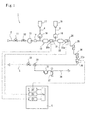
Figure 1] Figure 1 is a configuration diagram of a dialysis fluid preparation apparatus according to a first embodiment. - [
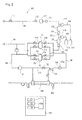
Figure 2] Figure 2 is a configuration diagram of a personal dialysis apparatus according to a second embodiment. - Hereinafter, embodiments shown in the drawings will be described.
Figure 1 shows a dialysis fluid preparation apparatus 1 that is installed in hospitals and the like. This dialysis fluid preparation apparatus 1 feeds a prepared dialysis fluid to a plurality of dialysis monitoring apparatuses not shown in the figure, as a so-called dialysis fluid feed apparatus for many persons. - The dialysis fluid preparation apparatus 1 includes a
water feed passage 2 that is connected with purified water feed means to feed purified water, which is not shown in the figure, anA fluid passage 3 that is connected with thewater feed passage 2 and feeds an A fluid as an undiluted fluid of the dialysis fluid, aB fluid passage 4 that is connected with thewater feed passage 2 and feeds a B fluid, and awaste fluid passage 5 that is led from thewater feed passage 2 and drains a poor dialysis fluid. The actuation of solenoid on-off valves and pumps of the dialysis fluid preparation apparatus 1 is controlled by a control means 6. - The A fluid as an undiluted fluid of the dialysis fluid contains sodium chloride as the principal ingredient, and other than sodium chloride, also contains ingredients such as glucose. The ratio is sometimes changed depending on patients using it, and therefore, the concentration of the A fluid itself sometimes varies for each dialysis fluid to be prepared.
- On the other hand, the B fluid as an undiluted fluid of the dialysis fluid is composed of an aqueous solution containing only sodium bicarbonate, and the B fluid has a constant concentration regardless of the dialysis fluid to be prepared.
- As described in detail later, the dialysis fluid preparation apparatus 1 has a self-check function to previously diagnose the devices constituting the dialysis fluid preparation apparatus 1 before preparing the dialysis fluid, and can switch between a diagnosis mode for performing the self-check and a preparation mode for performing the preparation of the dialysis fluid.
- The
B fluid passage 4 is connected upstream of theA fluid passage 3 on thewater feed passage 2. Upstream of the connecting position of theB fluid passage 4, a first on-offvalve 11 to open and close thewater feed passage 2, an adjustingvalve 12 to adjust the flow rate of the purified water in thewater feed passage 2, a purifiedwater pump 13 to send the purified water, and aflow meter 14 to measure the flow rate of the purified water are provided in the order from the upstream side. - The adjusting
valve 12, which is a needle valve, adjusts the flow rate of the purified water that the purifiedwater pump 13 sends, by the control of the control means 6. Theflow meter 14 measures the flow rate, and feeds back for the flow rate adjustment of the adjustingvalve 12. TheA fluid passage 3 has one end connected with anA fluid tank 15 in which the A fluid is pooled, and anA fluid pump 16 to send the A fluid is provided on theA fluid passage 3. Similarly to this, theB fluid passage 4 is connected with aB fluid tank 17 in which the B fluid is pooled, and aB fluid pump 18 to send the B fluid is provided on theB fluid passage 4. - The
A fluid pump 16 and theB fluid pump 18 are volume pumps respectively, and include motors not shown in the figure. By rotating these motors at predetermined rotation speeds, it is possible to feed the A fluid and the B fluid to thewater feed passage 2 at predetermined flow rates set in the control means 6. - Between the
B fluid passage 4 and theA fluid passage 3 on thewater feed passage 2, afirst buffer tank 19 for temporarily pooling liquid, adetection unit 20a of a first concentration measurement means 20 to measure the concentration of the liquid, and a first temperature measurement means 21 to measure the temperature of the liquid are provided in the order from the upstream side. - Downstream of the
A fluid passage 3 on thewater feed passage 2, asecond buffer tank 22 for temporarily pooling liquid, adetection unit 23a of a second concentration measurement means 23 to measure the concentration of the liquid, a second temperature measurement means 24 to measure the temperature of the liquid, afirst filter 25 andsecond filter 26 to purify the dialysis fluid, adetection unit 27a of a third concentration measurement means 27 to measure the concentration of the liquid, and a third temperature measurement means 28 to measure the temperature of the liquid are provided in the order from the upstream side. - Downstream of the third temperature measurement means 28, a
connection port 29 is provided at the boundary with thewaste fluid passage 5, and afluid feed passage 30 is provided at theconnection port 29. Further, afluid sending pump 31 to send the dialysis fluid and adrip chamber 32 are provided on thefluid feed passage 30, and a second on-offvalve 33 is provided on thewaste fluid passage 5 after theconnection port 29. - The first and
second buffer tanks water feed passage 2 is enlarged and liquid is stirred. In thefirst buffer tank 19, the B fluid and the purified water are mixed so that a preparation fluid of the B fluid is prepared. In thesecond buffer tank 22, the A fluid is mixed with the preparation fluid of the B fluid so that the dialysis fluid is prepared. - The ratio between the B fluid and the purified water in the preparation fluid of the B fluid that is prepared within the
first buffer tank 19 is identical to the ratio between the B fluid and the purified water in the dialysis fluid that is prepared by the dialysis fluid preparation apparatus 1. The concentration of the B fluid is previously measured, and is registered in the control means 6. - Also, as for the dialysis fluid that is prepared within the
second buffer tank 22, the concentration is previously measured, and is registered in the control means 6. As for this concentration, multiple kinds are registered depending on the A fluid to be used. - The first and
second filters - The first to third concentration measurement means 20, 23, 27 are concentration meters that convert the electric conductivities of the liquids, which are respectively measured by the first to
third detection units - The first to third temperature measurement means 21, 24, 28 are disposed adjacent to the first to
third detection units - When the dialysis fluid preparation apparatus 1 is in the preparation mode, the first concentration measurement means 20 measures the electric conductivity of the preparation fluid of the B fluid prepared in the
first buffer tank 19, and the second and third concentration measurement means 23, 27 measure the electric conductivity of the dialysis fluid prepared in thesecond buffer tank 22. - The control means 6 compares these electric conductivities of the preparation fluid of the B fluid and the dialysis fluid that are measured by the first to third concentration measurement means 20, 23, 27, with the previously registered electric conductivities of the preparation fluid of the B fluid and the dialysis fluid, and judges whether these electric conductivities are abnormal.
- Then, calcium carbonate is deposited from the preparation fluid of the B fluid and the dialysis fluid, and adheres to the electrodes of the
detection units - Thereby, the control means 6 includes a
diagnosis unit 6a for performing the self-check, and, in thisdiagnosis unit 6a, diagnoses the accuracy of the first to third concentration measurement means 20, 23, 27. - Hereinafter, the behavior of the dialysis fluid preparation apparatus 1 having the above configuration will be described. First, in a before-activation state of the dialysis fluid preparation apparatus 1, the
A fluid passage 3 and theB fluid passage 4 are connected with theA fluid tank 15 and theB fluid tank 17 in which the A fluid and B fluid to be used in the preparation of the dialysis fluid are pooled, respectively, and thewater feed passage 2 is filled with the purified water that has been used as rinse water after washing thewater feed passage 2 and in which the A fluid and the B fluid are not mixed. - In this state, once an operator operates an operation panel not shown in the figure to activate the dialysis fluid preparation apparatus 1, it becomes the diagnosis mode to actuate the self-check function and check the behavior of each of the solenoid on-off valves, pumps and measurement means, and therewith, the
diagnosis unit 6a of the control means 6 diagnoses the accuracy of the concentration measurement means. - In the following description, a diagnosis method for diagnosing the accuracy of the first to third concentration measurement means 20, 23, 27 will be described.
- First, the control means 6 closes the first on-off
valve 11 on thewater feed passage 2 while opening the second on-offvalve 33, stops the purifiedwater pump 13 and thefluid sending pump 31, and actuates theB fluid pump 18 on theB fluid passage 4. At this time, theA fluid pump 16 is being stopped. - Thereby, the B fluid, which is fed from the
B fluid tank 17, flows into thewater feed passage 2 through theB fluid passage 4, and the purified water filling thewater feed passage 2 is pushed to thewaste fluid passage 5. Eventually, thewater feed passage 2 becomes a state in which the downstream side of the connecting position of theB fluid passage 4 is filled with only the B fluid. - When, after the actuation of the
B fluid pump 18, enough time has elapsed for the B fluid to come to at least thedetection unit 27a of the third concentration measurement means 27, the control means 6 measures the electric conductivity with the first tothird detection units - Then, the
diagnosis unit 6a compares the measured electric conductivity with a previously set value (for example, 45.4 mS/cm, when a 7% sodium bicarbonate aqueous solution is used as the B undiluted fluid). - If the measured value of the B fluid measured at this time is in a predetermined error range for the previously set value, a diagnosis as being not abnormal is made in the
diagnosis unit 6a, and if exceeding the error range, a diagnosis as being abnormal is made. - If each of the concentration measurement means 20, 23, 27 is not abnormal, the control means 6 proceeds with an operation described below, and if being abnormal, the control means 6 gives a warning for the appropriate concentration measurement means.
- The control means 6 continuously measures the electric conductivity with the first concentration measurement means 20, after the
B fluid pump 18 starts to send the B fluid, and measures the time before the electric conductivity reaches the above predetermined value, that is, the time before the B fluid reaches thefirst detection unit 20a. - Then, the
diagnosis unit 6a compares the measured reaching time of the B fluid with a previously set standard time, and judges whether theB fluid pump 18 is abnormal. If the reaching time is later than the standard time, the fluid sending rate of theB fluid pump 18 is insufficient, and if being earlier, the fluid sending rate is greater than the specification. - After measuring the electric conductivity of the B fluid with the
detection units valve 11 on thewater feed passage 2, and further actuates the purifiedwater pump 13 to flow the purified water to thewater feed passage 2 at a predetermined flow rate. - On this occasion, the
B fluid pump 18 performs the fluid sending at a specified flow rate, and thereby, in thefirst buffer tank 19 on thewater feed passage 2, the B fluid and the purified water are mixed so that the preparation fluid of the B fluid is prepared at a predetermined concentration. This preparation fluid of the B fluid flows to thewaste fluid passage 5. - Similarly to the case of sending only the B fluid, the control means 6 measures the electric conductivity with the first to
third detection units diagnosis unit 6a compares the measured values with a previously set value corresponding to the concentration of the preparation fluid of the B fluid. - By measuring the concentrations of the B fluid and the preparation fluid of the B fluid, that is, the liquids with different electric conductivities, in this way, it is possible to diagnose the first to third concentration measurement means 20, 23, 27 more exactly.
- After measuring the electric conductivity of the preparation fluid of the B fluid with the
detection units A fluid pump 16 on theA fluid passage 3 to feed the A fluid to thewater feed passage 2. - On this occasion, also, the
B fluid pump 18 is actuated, and thereby, in thesecond buffer tank 22 positioned downstream of the connecting position of theA fluid passage 3, the A fluid is mixed to the preparation fluid of the B fluid so that the dialysis fluid is prepared. This dialysis fluid flows on thewater feed passage 2 to thewaste fluid passage 5. - The control means 6 measures the electric conductivity of the dialysis fluid with the
second detection unit 23a of the second concentration measurement means 23 and thethird detection unit 27a of the third concentration measurement means 27, compares it with a previously set value as the electric conductivity of the dialysis fluid, and judges whether the concentration of the dialysis fluid is good or poor. - Further, by measuring the time after the
A fluid pump 16 starts to feed the A fluid and before thesecond detection unit 23a measures the electric conductivity corresponding to the predetermined concentration of the dialysis fluid, it is possible to diagnose the fluid sending rate of theA fluid pump 16. - Thus, the diagnosis of the accuracy of the first to third concentration measurement means 20, 23, 27 is completed, and when the other devices also are not recognized to be abnormal, the control means 6 finishes the diagnosis of the dialysis fluid preparation apparatus 1. The dialysis fluid preparation apparatus 1 switches from the diagnosis mode to the preparation mode, and subsequently prepares the dialysis fluid.
- Thus, in the dialysis fluid preparation apparatus 1 according to the above embodiment, by the
diagnosis unit 6a provided in the control means 6, it is possible to automatically diagnose the accuracy of the first to third concentration measurement means 20, 23, 27. - Further, the B fluid to be used in the preparation of the dialysis fluid is utilized for diagnosing the first to third concentration measurement means 20, 23, 27, and therefore, special reagents or devices are not required for the diagnosis, and it is possible to simply perform the diagnosis.
- On this occasion, by measuring the reaching time before the B fluid reaches the detection unit of the concentration measurement means, it is possible to diagnose also the fluid sending rate of the
B fluid pump 18. - In addition, when diagnosing the first to third concentration measurement means 20, 23, 27, by measuring the B fluid and the preparation fluid of the B fluid, which are liquids with different electric conductivities, it is possible to perform an exact diagnosis.
- Although, in the above embodiment, the
B fluid passage 4 is connected upstream of theA fluid passage 3 on thewater feed passage 2, it can be connected downstream of theA fluid passage 3. - That is, it is possible to be configured such that, in
Figure 1 ,reference numeral 3 denotes the B fluid passage,reference numeral 4 denotes the A fluid passage,reference numerals reference numerals - In the case of such a configuration, for the diagnosis of the accuracy of the first to third concentration measurement means 20, 23, 27, first, by the same procedure as the above described procedure, the B fluid is sent to the second and
third detection units - Subsequently, for the diagnosis of the first concentration measurement means 20 disposed between the B fluid passage (3) and the A fluid passage (4), the first on-off
valve 11 on thewater feed passage 2 is closed while the second on-offvalve 33 is maintained in the open state, and the purifiedwater pump 13 and thefluid sending pump 31 are kept stopped. In that state, the A fluid pump (18) is inversely rotated. - Then, the B fluid filling the downstream side of the connecting position of the
B fluid passage 3 on thewater feed passage 2 flows backward to thefirst detection unit 20a of the first concentration measurement means 20. Thereby, it is possible to measure the electric conductivity of the B fluid and diagnose the first concentration measurement means 20. - As another method for the diagnosis of the first concentration measurement means 20, in a state in which the second and third concentration measurement means 23, 27 have been diagnosed, the first on-off
valve 11 on thewater feed passage 2 is closed, and the purifiedwater pump 13 and thefluid sending pump 31 are kept stopped. In that state, the second on-offvalve 33 is closed. - Furthermore, once the B fluid pump (16) is actuated and the A fluid pump (18) is inversely rotated at the same speed as the B fluid pump (16), the B fluid flows backward to the
first detection unit 20a of the first concentration measurement means 20. Thereby, it is possible to measure the electric conductivity of the B fluid and diagnose the first concentration measurement means 20. - Here, in the case of providing the A fluid passage (4) upstream of the B fluid passage (3) and inversely rotating the A fluid pump (18) in this way, it is preferable to set a limit on the inverse rotation amount of the A fluid pump (18), in order not to enter the B fluid into the A fluid tank (17).
-
Figure 2 , which shows a second embodiment, illustrates a configuration diagram of a so-calledpersonal dialysis apparatus 101. Thispersonal dialysis apparatus 101 has also a function as the diagnosis fluid preparation apparatus 1 shown inFigure 1 , and can prepare the diagnosis fluid. - In the following embodiment, as for common constituents with the above first embodiment, reference numerals resulting from adding 100 to the reference numerals used in the first embodiment are used, and detailed descriptions are omitted.
- The
personal dialysis apparatus 101 includes adialyzer 106 to perform the dialysis between blood and dialysis fluid, ablood circuit 107 to be connected between thedialyzer 106 and a patient, and first and second chambers C1, C2 to feed fresh dialysis fluid to thedialyzer 106 and retrieve used dialysis fluid. - The first and second chambers C1, C2 are respectively divided into feed chambers C1b, C2b in which the fresh dialysis fluid is pooled by diaphragms C1a, C2a having flexibility, and retrieval chambers C1c, C2c in which the used dialysis fluid is pooled.
- The feed chambers C1b, C2b are connected with a
water feed passage 102 and afluid feed passage 108 that feeds the fresh dialysis fluid to thedialyzer 106, and the retrieval chambers C1c, C2c are connected with awaste fluid passage 105 and aretrieval passage 109 that retrieves the used diagnosis fluid from thedialyzer 106. On these passages, various solenoid on-off valves are provided respectively. - The
water feed passage 2 in the first embodiment corresponds to thewater feed passage 102 andfluid feed passage 108 in the second embodiment, and thedetection unit 127a of the third concentration measurement means 127, the third temperature measurement means 128 and thefirst filter 125 are each provided on thefluid feed passage 108. - The third concentration measurement means 127 and the third temperature measurement means 128 are provided upstream of the
first filter 125 on thefluid feed passage 108, and thesecond filter 26 in the first embodiment is omitted. Further, the fluid sending pump 130 is provided on theretrieval passage 109. - A
bypass passage 110 is formed between thefirst filter 125 and theretrieval passage 109, and by opening a second on-offvalve 132 provided on thebypass passage 110, the dialysis fluid judged as a poor concentration is drained. - The
personal dialysis apparatus 101 having the above described configuration, itself, is known conventionally, and therefore, detailed descriptions of the behavior are omitted. Similarly to the above first embodiment, thepersonal dialysis apparatus 101 can diagnose the accuracy of the first to third concentration measurement means 120, 123, 127 with adiagnosis unit 106a provided in a control means 106, and can also diagnose the fluid sending rate of aB fluid pump 118 and anA fluid pump 116. - Here, in the configuration of the second embodiment, also, it is possible to connect the B fluid passage downstream of the A fluid passage, and even if such a configuration, it is possible to diagnose the accuracy of the first to third concentration measurement means 120, 123, 127.
-
- 1
- dialysis fluid preparation apparatus
- 2
- water feed passage
- 3
- A fluid passage
- 4
- B fluid passage
- 5
- waste fluid passage
- 6
- control means
- 6a
- diagnosis unit
- 15
- A fluid tank
- 16
- A fluid pump
- 17
- B fluid tank
- 18
- B fluid pump
- 20
- first concentration measurement means
- 20a
- first detection unit
- 23
- second concentration measurement means
- 23a
- second detection unit
- 27
- third concentration measurement means
- 27a
- third detection unit
Claims (4)
- A diagnosis method for a dialysis fluid preparation apparatus that comprises: a water feed passage to feed purified water; an A fluid passage to feed an A fluid containing sodium chloride as a principal ingredient, the A fluid passage being connected with the water feed passage; a B fluid passage to feed a B fluid composed of a sodium bicarbonate aqueous solution, the B fluid passage being connected with the water feed passage; and concentration measurement means provided with a detection unit downstream of connecting positions of the A fluid passage and the B fluid passage on the water feed passage,
the dialysis fluid preparation apparatus mixing the purified water, the A fluid and the B fluid in predetermined proportions respectively to prepare a dialysis fluid, and measuring a concentration of the prepared dialysis fluid by the concentration measurement means,
wherein the diagnosis method for the dialysis fluid preparation apparatus, before preparing the dialysis fluid, feeds the B fluid from the B fluid passage to the water feed passage so as to flow only the B fluid to the water feed passage, and
diagnoses accuracy of the concentration measurement means by measuring an electric conductivity of the B fluid by the concentration measurement means and then comparing the measured electric conductivity of the B fluid with a previously set value. - The diagnosis method for the dialysis fluid preparation apparatus according to claim 1,
wherein the diagnosis method for the dialysis fluid preparation apparatus, when measuring the electric conductivity of the B fluid, measures a time after a B fluid pump starts a fluid sending of the B fluid and before the concentration measurement means measures a concentration of the B fluid, the B fluid pump being provided on the B fluid passage and feeding the B fluid to the water feed passage, and thereby
diagnoses fluid sending accuracy of the B fluid pump. - The diagnosis method for the dialysis fluid preparation apparatus according to any one of claims 1 and 2,
wherein the diagnosis method for the dialysis fluid preparation apparatus, after measuring the electric conductivity of the B fluid, mixes the purified water and the B fluid to prepare a preparation fluid of the B fluid by flowing the purified water to the water feed passage, and
diagnoses the accuracy of the concentration measurement means by measuring an electric conductivity of the preparation fluid of the B fluid by the concentration measurement means and then comparing the measured electric conductivity of the preparation fluid of the B fluid with a previously set value. - A dialysis fluid preparation apparatus that comprises: a water feed passage to flow purified water; a water feed pump provided on the water feed passage; an A fluid passage to feed an A fluid containing sodium chloride as a principal ingredient, the A fluid passage being connected with the water feed passage; an A fluid pump provided on the A fluid passage; a B fluid passage to feed a B fluid composed of a sodium bicarbonate aqueous solution, the B fluid passage being connected with the water feed passage; a B fluid pump provided on the B fluid passage; concentration measurement means provided with a detection unit downstream of connecting positions of the A fluid passage and the B fluid passage on the water feed passage; and control means to control actuations of the pumps, the dialysis fluid preparation apparatus mixing the purified water, the A fluid and the B fluid in predetermined proportions to prepare a dialysis fluid,
wherein the control means is provided with a diagnosis unit to diagnose accuracy of the concentration measurement means,
the control means actuates the B fluid pump to perform a fluid sending of only the B fluid to the water feed passage, without performing a fluid sending with the water feed pump and the A fluid pump, and
the diagnosis unit diagnoses the accuracy of the concentration measurement means by comparing an electric conductivity of the B fluid measured by the detection unit of the concentration measurement means with a previously set value.
Applications Claiming Priority (2)
| Application Number | Priority Date | Filing Date | Title |
|---|---|---|---|
| JP2011224216A JP5803543B2 (en) | 2011-10-11 | 2011-10-11 | Dialysis fluid preparation device diagnostic method and dialysis fluid preparation device |
| PCT/JP2012/076275 WO2013054826A1 (en) | 2011-10-11 | 2012-10-11 | Diagnostic method of dialysate preparation device, and dialysate preparation device |
Publications (3)
| Publication Number | Publication Date |
|---|---|
| EP2767296A1 true EP2767296A1 (en) | 2014-08-20 |
| EP2767296A4 EP2767296A4 (en) | 2015-06-10 |
| EP2767296B1 EP2767296B1 (en) | 2016-07-20 |
Family
ID=48081879
Family Applications (1)
| Application Number | Title | Priority Date | Filing Date |
|---|---|---|---|
| EP12839867.4A Not-in-force EP2767296B1 (en) | 2011-10-11 | 2012-10-11 | Diagnostic method of dialysate preparation device, and dialysate preparation device |
Country Status (3)
| Country | Link |
|---|---|
| EP (1) | EP2767296B1 (en) |
| JP (1) | JP5803543B2 (en) |
| WO (1) | WO2013054826A1 (en) |
Cited By (4)
| Publication number | Priority date | Publication date | Assignee | Title |
|---|---|---|---|---|
| DE102017000495A1 (en) | 2017-01-20 | 2018-07-26 | Fresenius Medical Care Deutschland Gmbh | DlALYSATKONZENTRATlON-MESSSENSORDlAGNOSE |
| EP3238755B1 (en) | 2014-12-25 | 2019-02-20 | Asahi Kasei Medical Co., Ltd. | Solution producing device and blood purification system |
| WO2025082932A1 (en) | 2023-10-18 | 2025-04-24 | Gambro Lundia Ab | Dialysis fluid generation apparatus |
| EP4570279A1 (en) * | 2023-12-13 | 2025-06-18 | B. Braun Avitum AG | Process for determining the sodium and bicarbonate ion concentration of a dialysis fluid, use of a method for proportioning dialysis fluid |
Families Citing this family (4)
| Publication number | Priority date | Publication date | Assignee | Title |
|---|---|---|---|---|
| JP6269943B2 (en) * | 2014-02-24 | 2018-01-31 | 澁谷工業株式会社 | Hemodialysis machine |
| JP6286073B2 (en) * | 2015-02-06 | 2018-02-28 | 旭化成メディカル株式会社 | Treatment liquid preparation device and blood treatment system |
| JP6892602B2 (en) * | 2017-08-10 | 2021-06-23 | 澁谷工業株式会社 | Component monitoring method in dialysate preparation system |
| JP6914803B2 (en) * | 2017-10-17 | 2021-08-04 | 日機装株式会社 | Blood purification device |
Family Cites Families (6)
| Publication number | Priority date | Publication date | Assignee | Title |
|---|---|---|---|---|
| CA1166966A (en) * | 1980-05-09 | 1984-05-08 | Albert L. Babb | System for bicarbonate dialysate |
| DE4139165C2 (en) * | 1991-11-28 | 1994-12-08 | Fresenius Ag | Device for the production of a medical fluid |
| JPH06142191A (en) | 1992-11-05 | 1994-05-24 | Asahi Medical Co Ltd | Abnormality diagnosing method for dialysis monitoring device |
| PT597817E (en) * | 1992-11-12 | 2003-11-28 | Baxter Int | METHOD AND APPARATUS FOR DIALYSIS RENAL |
| US20100051552A1 (en) * | 2008-08-28 | 2010-03-04 | Baxter International Inc. | In-line sensors for dialysis applications |
| JP5423318B2 (en) * | 2009-10-29 | 2014-02-19 | ニプロ株式会社 | Dialysate concentration monitoring device and operating method thereof |
-
2011
- 2011-10-11 JP JP2011224216A patent/JP5803543B2/en active Active
-
2012
- 2012-10-11 EP EP12839867.4A patent/EP2767296B1/en not_active Not-in-force
- 2012-10-11 WO PCT/JP2012/076275 patent/WO2013054826A1/en not_active Ceased
Cited By (6)
| Publication number | Priority date | Publication date | Assignee | Title |
|---|---|---|---|---|
| EP3238755B1 (en) | 2014-12-25 | 2019-02-20 | Asahi Kasei Medical Co., Ltd. | Solution producing device and blood purification system |
| DE102017000495A1 (en) | 2017-01-20 | 2018-07-26 | Fresenius Medical Care Deutschland Gmbh | DlALYSATKONZENTRATlON-MESSSENSORDlAGNOSE |
| WO2018134045A1 (en) | 2017-01-20 | 2018-07-26 | Fresenius Medical Care Deutschland Gmbh | Dialysate concentration measurement sensor diagnosis |
| US11504459B2 (en) | 2017-01-20 | 2022-11-22 | Fresentus Medical Care Deutschland Gmbh | Dialysate concentration measurement sensor diagnosis |
| WO2025082932A1 (en) | 2023-10-18 | 2025-04-24 | Gambro Lundia Ab | Dialysis fluid generation apparatus |
| EP4570279A1 (en) * | 2023-12-13 | 2025-06-18 | B. Braun Avitum AG | Process for determining the sodium and bicarbonate ion concentration of a dialysis fluid, use of a method for proportioning dialysis fluid |
Also Published As
| Publication number | Publication date |
|---|---|
| EP2767296A4 (en) | 2015-06-10 |
| JP5803543B2 (en) | 2015-11-04 |
| JP2013081662A (en) | 2013-05-09 |
| WO2013054826A1 (en) | 2013-04-18 |
| EP2767296B1 (en) | 2016-07-20 |
Similar Documents
| Publication | Publication Date | Title |
|---|---|---|
| EP2767296B1 (en) | Diagnostic method of dialysate preparation device, and dialysate preparation device | |
| US11433170B2 (en) | Dialysis systems, devices, and methods | |
| US8518258B2 (en) | Hemodialysis device, hemodiafiltration device, method for taking a sample in corresponding devices and sampling kit for use in corresponding devices and method | |
| EP2494998B1 (en) | Method for monitoring dialysate concentration and device therefor | |
| US9861733B2 (en) | Peritoneal dialysis systems, devices, and methods | |
| KR100636045B1 (en) | Method and apparatus for performing controlled ultrafiltration during hemodialysis | |
| US11504459B2 (en) | Dialysate concentration measurement sensor diagnosis | |
| CN109562215B (en) | Method for monitoring bicarbonate content and sodium content of dialysate |
Legal Events
| Date | Code | Title | Description |
|---|---|---|---|
| PUAI | Public reference made under article 153(3) epc to a published international application that has entered the european phase |
Free format text: ORIGINAL CODE: 0009012 |
|
| 17P | Request for examination filed |
Effective date: 20140429 |
|
| AK | Designated contracting states |
Kind code of ref document: A1 Designated state(s): AL AT BE BG CH CY CZ DE DK EE ES FI FR GB GR HR HU IE IS IT LI LT LU LV MC MK MT NL NO PL PT RO RS SE SI SK SM TR |
|
| DAX | Request for extension of the european patent (deleted) | ||
| RA4 | Supplementary search report drawn up and despatched (corrected) |
Effective date: 20150511 |
|
| RIC1 | Information provided on ipc code assigned before grant |
Ipc: A61M 1/14 20060101AFI20150504BHEP Ipc: A61M 1/16 20060101ALI20150504BHEP |
|
| GRAP | Despatch of communication of intention to grant a patent |
Free format text: ORIGINAL CODE: EPIDOSNIGR1 |
|
| INTG | Intention to grant announced |
Effective date: 20160226 |
|
| GRAS | Grant fee paid |
Free format text: ORIGINAL CODE: EPIDOSNIGR3 |
|
| GRAA | (expected) grant |
Free format text: ORIGINAL CODE: 0009210 |
|
| AK | Designated contracting states |
Kind code of ref document: B1 Designated state(s): AL AT BE BG CH CY CZ DE DK EE ES FI FR GB GR HR HU IE IS IT LI LT LU LV MC MK MT NL NO PL PT RO RS SE SI SK SM TR |
|
| REG | Reference to a national code |
Ref country code: GB Ref legal event code: FG4D |
|
| REG | Reference to a national code |
Ref country code: CH Ref legal event code: EP |
|
| REG | Reference to a national code |
Ref country code: IE Ref legal event code: FG4D |
|
| REG | Reference to a national code |
Ref country code: AT Ref legal event code: REF Ref document number: 813523 Country of ref document: AT Kind code of ref document: T Effective date: 20160815 |
|
| REG | Reference to a national code |
Ref country code: DE Ref legal event code: R096 Ref document number: 602012020860 Country of ref document: DE |
|
| REG | Reference to a national code |
Ref country code: LT Ref legal event code: MG4D |
|
| REG | Reference to a national code |
Ref country code: NL Ref legal event code: MP Effective date: 20160720 |
|
| REG | Reference to a national code |
Ref country code: AT Ref legal event code: MK05 Ref document number: 813523 Country of ref document: AT Kind code of ref document: T Effective date: 20160720 |
|
| PG25 | Lapsed in a contracting state [announced via postgrant information from national office to epo] |
Ref country code: IT Free format text: LAPSE BECAUSE OF FAILURE TO SUBMIT A TRANSLATION OF THE DESCRIPTION OR TO PAY THE FEE WITHIN THE PRESCRIBED TIME-LIMIT Effective date: 20160720 Ref country code: HR Free format text: LAPSE BECAUSE OF FAILURE TO SUBMIT A TRANSLATION OF THE DESCRIPTION OR TO PAY THE FEE WITHIN THE PRESCRIBED TIME-LIMIT Effective date: 20160720 Ref country code: LT Free format text: LAPSE BECAUSE OF FAILURE TO SUBMIT A TRANSLATION OF THE DESCRIPTION OR TO PAY THE FEE WITHIN THE PRESCRIBED TIME-LIMIT Effective date: 20160720 Ref country code: NL Free format text: LAPSE BECAUSE OF FAILURE TO SUBMIT A TRANSLATION OF THE DESCRIPTION OR TO PAY THE FEE WITHIN THE PRESCRIBED TIME-LIMIT Effective date: 20160720 Ref country code: RS Free format text: LAPSE BECAUSE OF FAILURE TO SUBMIT A TRANSLATION OF THE DESCRIPTION OR TO PAY THE FEE WITHIN THE PRESCRIBED TIME-LIMIT Effective date: 20160720 Ref country code: FI Free format text: LAPSE BECAUSE OF FAILURE TO SUBMIT A TRANSLATION OF THE DESCRIPTION OR TO PAY THE FEE WITHIN THE PRESCRIBED TIME-LIMIT Effective date: 20160720 Ref country code: IS Free format text: LAPSE BECAUSE OF FAILURE TO SUBMIT A TRANSLATION OF THE DESCRIPTION OR TO PAY THE FEE WITHIN THE PRESCRIBED TIME-LIMIT Effective date: 20161120 Ref country code: NO Free format text: LAPSE BECAUSE OF FAILURE TO SUBMIT A TRANSLATION OF THE DESCRIPTION OR TO PAY THE FEE WITHIN THE PRESCRIBED TIME-LIMIT Effective date: 20161020 |
|
| PG25 | Lapsed in a contracting state [announced via postgrant information from national office to epo] |
Ref country code: BE Free format text: LAPSE BECAUSE OF NON-PAYMENT OF DUE FEES Effective date: 20160720 Ref country code: GR Free format text: LAPSE BECAUSE OF FAILURE TO SUBMIT A TRANSLATION OF THE DESCRIPTION OR TO PAY THE FEE WITHIN THE PRESCRIBED TIME-LIMIT Effective date: 20161021 Ref country code: ES Free format text: LAPSE BECAUSE OF FAILURE TO SUBMIT A TRANSLATION OF THE DESCRIPTION OR TO PAY THE FEE WITHIN THE PRESCRIBED TIME-LIMIT Effective date: 20160720 Ref country code: AT Free format text: LAPSE BECAUSE OF FAILURE TO SUBMIT A TRANSLATION OF THE DESCRIPTION OR TO PAY THE FEE WITHIN THE PRESCRIBED TIME-LIMIT Effective date: 20160720 Ref country code: PL Free format text: LAPSE BECAUSE OF FAILURE TO SUBMIT A TRANSLATION OF THE DESCRIPTION OR TO PAY THE FEE WITHIN THE PRESCRIBED TIME-LIMIT Effective date: 20160720 Ref country code: SE Free format text: LAPSE BECAUSE OF FAILURE TO SUBMIT A TRANSLATION OF THE DESCRIPTION OR TO PAY THE FEE WITHIN THE PRESCRIBED TIME-LIMIT Effective date: 20160720 Ref country code: LV Free format text: LAPSE BECAUSE OF FAILURE TO SUBMIT A TRANSLATION OF THE DESCRIPTION OR TO PAY THE FEE WITHIN THE PRESCRIBED TIME-LIMIT Effective date: 20160720 Ref country code: PT Free format text: LAPSE BECAUSE OF FAILURE TO SUBMIT A TRANSLATION OF THE DESCRIPTION OR TO PAY THE FEE WITHIN THE PRESCRIBED TIME-LIMIT Effective date: 20161121 |
|
| REG | Reference to a national code |
Ref country code: DE Ref legal event code: R097 Ref document number: 602012020860 Country of ref document: DE |
|
| PG25 | Lapsed in a contracting state [announced via postgrant information from national office to epo] |
Ref country code: EE Free format text: LAPSE BECAUSE OF FAILURE TO SUBMIT A TRANSLATION OF THE DESCRIPTION OR TO PAY THE FEE WITHIN THE PRESCRIBED TIME-LIMIT Effective date: 20160720 Ref country code: RO Free format text: LAPSE BECAUSE OF FAILURE TO SUBMIT A TRANSLATION OF THE DESCRIPTION OR TO PAY THE FEE WITHIN THE PRESCRIBED TIME-LIMIT Effective date: 20160720 |
|
| PLBE | No opposition filed within time limit |
Free format text: ORIGINAL CODE: 0009261 |
|
| STAA | Information on the status of an ep patent application or granted ep patent |
Free format text: STATUS: NO OPPOSITION FILED WITHIN TIME LIMIT |
|
| PG25 | Lapsed in a contracting state [announced via postgrant information from national office to epo] |
Ref country code: CZ Free format text: LAPSE BECAUSE OF FAILURE TO SUBMIT A TRANSLATION OF THE DESCRIPTION OR TO PAY THE FEE WITHIN THE PRESCRIBED TIME-LIMIT Effective date: 20160720 Ref country code: SK Free format text: LAPSE BECAUSE OF FAILURE TO SUBMIT A TRANSLATION OF THE DESCRIPTION OR TO PAY THE FEE WITHIN THE PRESCRIBED TIME-LIMIT Effective date: 20160720 Ref country code: BG Free format text: LAPSE BECAUSE OF FAILURE TO SUBMIT A TRANSLATION OF THE DESCRIPTION OR TO PAY THE FEE WITHIN THE PRESCRIBED TIME-LIMIT Effective date: 20161020 Ref country code: SM Free format text: LAPSE BECAUSE OF FAILURE TO SUBMIT A TRANSLATION OF THE DESCRIPTION OR TO PAY THE FEE WITHIN THE PRESCRIBED TIME-LIMIT Effective date: 20160720 Ref country code: DK Free format text: LAPSE BECAUSE OF FAILURE TO SUBMIT A TRANSLATION OF THE DESCRIPTION OR TO PAY THE FEE WITHIN THE PRESCRIBED TIME-LIMIT Effective date: 20160720 |
|
| REG | Reference to a national code |
Ref country code: CH Ref legal event code: PL |
|
| 26N | No opposition filed |
Effective date: 20170421 |
|
| GBPC | Gb: european patent ceased through non-payment of renewal fee |
Effective date: 20161020 |
|
| REG | Reference to a national code |
Ref country code: IE Ref legal event code: MM4A |
|
| REG | Reference to a national code |
Ref country code: FR Ref legal event code: ST Effective date: 20170630 |
|
| PG25 | Lapsed in a contracting state [announced via postgrant information from national office to epo] |
Ref country code: GB Free format text: LAPSE BECAUSE OF NON-PAYMENT OF DUE FEES Effective date: 20161020 Ref country code: FR Free format text: LAPSE BECAUSE OF NON-PAYMENT OF DUE FEES Effective date: 20161102 Ref country code: CH Free format text: LAPSE BECAUSE OF NON-PAYMENT OF DUE FEES Effective date: 20161031 Ref country code: LI Free format text: LAPSE BECAUSE OF NON-PAYMENT OF DUE FEES Effective date: 20161031 |
|
| PG25 | Lapsed in a contracting state [announced via postgrant information from national office to epo] |
Ref country code: SI Free format text: LAPSE BECAUSE OF FAILURE TO SUBMIT A TRANSLATION OF THE DESCRIPTION OR TO PAY THE FEE WITHIN THE PRESCRIBED TIME-LIMIT Effective date: 20160720 Ref country code: LU Free format text: LAPSE BECAUSE OF NON-PAYMENT OF DUE FEES Effective date: 20161011 |
|
| PG25 | Lapsed in a contracting state [announced via postgrant information from national office to epo] |
Ref country code: IE Free format text: LAPSE BECAUSE OF NON-PAYMENT OF DUE FEES Effective date: 20161011 |
|
| PG25 | Lapsed in a contracting state [announced via postgrant information from national office to epo] |
Ref country code: HU Free format text: LAPSE BECAUSE OF FAILURE TO SUBMIT A TRANSLATION OF THE DESCRIPTION OR TO PAY THE FEE WITHIN THE PRESCRIBED TIME-LIMIT; INVALID AB INITIO Effective date: 20121011 |
|
| PG25 | Lapsed in a contracting state [announced via postgrant information from national office to epo] |
Ref country code: MK Free format text: LAPSE BECAUSE OF FAILURE TO SUBMIT A TRANSLATION OF THE DESCRIPTION OR TO PAY THE FEE WITHIN THE PRESCRIBED TIME-LIMIT Effective date: 20160720 Ref country code: CY Free format text: LAPSE BECAUSE OF FAILURE TO SUBMIT A TRANSLATION OF THE DESCRIPTION OR TO PAY THE FEE WITHIN THE PRESCRIBED TIME-LIMIT Effective date: 20160720 Ref country code: MC Free format text: LAPSE BECAUSE OF FAILURE TO SUBMIT A TRANSLATION OF THE DESCRIPTION OR TO PAY THE FEE WITHIN THE PRESCRIBED TIME-LIMIT Effective date: 20160720 Ref country code: MT Free format text: LAPSE BECAUSE OF NON-PAYMENT OF DUE FEES Effective date: 20161031 |
|
| PG25 | Lapsed in a contracting state [announced via postgrant information from national office to epo] |
Ref country code: AL Free format text: LAPSE BECAUSE OF FAILURE TO SUBMIT A TRANSLATION OF THE DESCRIPTION OR TO PAY THE FEE WITHIN THE PRESCRIBED TIME-LIMIT Effective date: 20160720 Ref country code: TR Free format text: LAPSE BECAUSE OF FAILURE TO SUBMIT A TRANSLATION OF THE DESCRIPTION OR TO PAY THE FEE WITHIN THE PRESCRIBED TIME-LIMIT Effective date: 20160720 |
|
| PGFP | Annual fee paid to national office [announced via postgrant information from national office to epo] |
Ref country code: DE Payment date: 20231027 Year of fee payment: 12 |
|
| REG | Reference to a national code |
Ref country code: DE Ref legal event code: R119 Ref document number: 602012020860 Country of ref document: DE |
|
| PG25 | Lapsed in a contracting state [announced via postgrant information from national office to epo] |
Ref country code: DE Free format text: LAPSE BECAUSE OF NON-PAYMENT OF DUE FEES Effective date: 20250501 |