EP2767192A1 - Feeder device for presenting products on a shelf - Google Patents
Feeder device for presenting products on a shelf Download PDFInfo
- Publication number
- EP2767192A1 EP2767192A1 EP13163994.0A EP13163994A EP2767192A1 EP 2767192 A1 EP2767192 A1 EP 2767192A1 EP 13163994 A EP13163994 A EP 13163994A EP 2767192 A1 EP2767192 A1 EP 2767192A1
- Authority
- EP
- European Patent Office
- Prior art keywords
- sled
- guide member
- shelf
- spring
- damper
- Prior art date
- Legal status (The legal status is an assumption and is not a legal conclusion. Google has not performed a legal analysis and makes no representation as to the accuracy of the status listed.)
- Withdrawn
Links
Images




Classifications
-
- A—HUMAN NECESSITIES
- A47—FURNITURE; DOMESTIC ARTICLES OR APPLIANCES; COFFEE MILLS; SPICE MILLS; SUCTION CLEANERS IN GENERAL
- A47F—SPECIAL FURNITURE, FITTINGS, OR ACCESSORIES FOR SHOPS, STOREHOUSES, BARS, RESTAURANTS OR THE LIKE; PAYING COUNTERS
- A47F1/00—Racks for dispensing merchandise; Containers for dispensing merchandise
- A47F1/04—Racks or containers with arrangements for dispensing articles, e.g. by means of gravity or springs
- A47F1/12—Racks or containers with arrangements for dispensing articles, e.g. by means of gravity or springs dispensing from the side of an approximately horizontal stack
- A47F1/125—Racks or containers with arrangements for dispensing articles, e.g. by means of gravity or springs dispensing from the side of an approximately horizontal stack with an article-pushing device
- A47F1/126—Racks or containers with arrangements for dispensing articles, e.g. by means of gravity or springs dispensing from the side of an approximately horizontal stack with an article-pushing device the pushing device being urged by spring means
Definitions
- the present disclosure relates to a feeder device configured for mounting on a shelf for feeding successive products to a front of the shelf.
- the feeder device comprises a spring arranged to act on a sled for pushing the products towards the front of the shelf.
- the feeder device may be used e.g. in shops such as grocery stores or the like for providing and displaying products on shelves therein.
- An in-between set of solutions focuses on preventing potential buyers from taking more than one pack at the time, so called anti-sweep solutions. More or less successful prior art solutions to provide this feature exists for peg hooks.
- Feeder devices for merchandising in general are used for example in grocery stores where goods are exposed on the shelves. Indexing devices are used to push forward placed goods or store items, one behind the other, to the shelf edge, to facilitate the picking of the goods, improve visibility of the goods and make the shelf aesthetic appearance more appealing.
- the feeder device includes a base or web which is placed on the shelf so that it extends from the shelf front edge in a rearward direction.
- a feed sled is slidably disposed on the base along its length.
- the automatic feeder devices are sled biased, for example by a helical spring which is arranged on the backside of the sled and which at one end is attached to the front end of the base.
- the dividers comprise a dividing wall that extends from the shelf front edge in an essentially rearward direction.
- Dividers may also comprise a front stop plate or front extending perpendicularly to dividing wall on one or both sides of said wall, to prevent goods from falling off the shelf.
- the dividers are attached to the shelf next to each other to form compartments in which the feeder devices are placed.
- the distance between dividers are chosen in accordance with the relevant goods width, so that the goods are brought into line with each other in their respective compartments. This minimizes the space required to store the goods on the shelf, while the shelf aesthetic appearance becomes more appealing.
- dividers can be designed in a variety of ways.
- the dividing wall height may vary widely.
- the fronts of the dividers can be designed in a variety of ways, for example as regards the width, height and contour, to suit different goods and to provide desired visual impact for every occasion.
- Feeder devices and dividers should be easy to assemble and disassemble from the shelf.
- the feeder devices and the partitions are possible to fix at arbitrary positions laterally along the shelf, to thereby provide goods compartment with the desired width.
- EP 0 337 340 discloses a shelf divider system comprising a divider wall mountable in a channel member secured to the front of a shelf.
- a spring-urged pusher member is slidably mounted on a track having a pair of rails integral with the divider shaft.
- the operationally mounted divider wall is vertically oriented and the pusher member extends horizontally therefrom so that displayed merchandise resets directly on the shelf surface but is automatically urged forwardly by the retracted pusher member.
- the track provides the supporting surface for displayed merchandise and a vertical divider wall is integrally formed with the track.
- a general problem with spring urged feeder devices which pushes goods forward to the front edge of a store shelf is that goods items in line behind the front item being picked may be disrupted as the spring pushes them forward, and items may then be out of the feeder device and end up on the floor of the grocery store or the like.
- Another general problem is that it is easy to pick many of the lined up goods items at the same time, which may facilitate theft.
- EP 1 806 076 discloses a pusher apparatus e.g. for pushing a row of cigarette packets towards the front of a shelf.
- the leading package is arranged to drop down a step at one end of a track and be held in the dropped position against a stop by gentle pressure on the entire row from a pusher.
- a damped movement connection for example a rack engaged by a damped pinion mounted on the pusher
- the movement of the pusher itself maybe sufficiently damped to enable certain and repeatable dropping of the leading package as the row of packages is advanced, following the repeated removal of the leading one.
- the pinion of the pusher is engaged with a track along the row of packets and dampens the forward motion of the pusher.
- the drop down a step of the leading packet ensures that the front packet is easily accessible.
- Embodiments of the present invention provide an anti-sweep solution (theft deterrence where a person is prevented from easily sweep many products at the same time from e.g. a shelf) for theft prone products like razor blades or batteries.
- Another objective of the invention is to provide a delay in feeding the next product to the shelf edge. This feature is beneficial in product categories where consumers want to have the opportunity to pick up and look at packaging, and then also have the ability to easily put the pack back, before making their final choice.
- a feeder device configured for being mounted on a shelf for feeding successive products to a front of the shelf.
- the shelf may e.g. be a shelf in a shop such as a grocery store or department store or the like.
- the feeder device comprises an elongated guide member which is configured for extending longitudinally backwards from the front of the shelf when the device is mounted.
- the feeder device also comprises a sled which is slidably connected to the guide member such that the sled can slide along the length of the elongated guide member. The sled is configured for engaging a back-most product of the successive products for pushing the products towards the front of the shelf.
- the feeder device also comprises a spring connected to the sled (e.g. engaging or being attached to the sled), and configured for pushing the sled along the guide member towards a front end of said guide member.
- the feeder device further comprises a damper connected to the sled, and engaging the spring for damping the sliding motion of the sled towards the front end of the guiding member when the sled is pushed by the spring.
- the damper By using a damper which dampens the motion of the sled when it pushes the products towards the front of the shelf, the risk of products becoming disarrayed or unintentionally pushed out from the feeder device is reduced. A more controlled motion is achieved.
- the damper in cooperation with and engaging the spring can provide a slow and controlled feeding forward of the succeeding successive products towards the shelf front. Apart from reducing the risk of disarray that a fast and less controlled motion might result in, the slower and more controlled motion is more pleasing aesthetically. Also, the slower feeding forward of succeeding products may prolong the time until the next product is readily accessible for picking, which may reduce the risk of theft of many products at the same time.
- the elongated guide member has as a main function to guide the sled in a longitudinal direction along the guide member.
- the sled may be connected to the guide member by gravity in combination with a longitudinal ledge, flange or other protrusion of the guide member against which the sled can abut and be guided by.
- the sled may be slidably connected to the guide member by being able to slide on respective sliding surfaces e.g. rails of the sled and guide member, or slide enhancing means such as rolls or the like may be provided on the sled and/or on the guide member for facilitating the sliding of the sled in relation to the guide member.
- slide enhancing material e.g. in the form of a strip or tape.
- That the products are successive implies that they form a longitudinal queue along the guide member.
- the damper is a rotary damper.
- a rotary damper may be convenient since it may be mounted on the sled and provide damping for a sliding motion along essentially the whole guide member, whereas e.g. a gas damper, which is also contemplated, due to its telescopic structure may only be able to provide damping over a part of the guide member.
- the rotary damper may comprise a sprocket configured for being in mesh with e.g. the spring. Such a sprocket may alternatively be called e.g. gear, pinion or cogwheel. The sprocket may be in mesh with a for that purpose arranged structure or track on the spring.
- the spring comprises a plurality of longitudinally aligned recesses or holes (blind or through holes) configured for meshing with the sprocket of the rotary damper.
- the recesses or holes are longitudinally aligned such that they form a longitudinal track which is adapted to engage the sprocket as the sled to which the damper is connected slides along the guide member.
- the track of holes along the spring may extend past a longitudinal side edge of the spring, forming a (saw) toothed longitudinal side edge with which the sprocket may mesh.
- the spring is a spiral spring which is, at one of its ends, fastened or otherwise attached to a roll arranged in or otherwise connected to the sled.
- the spring is thus wound or rolled up onto (around) the roll when the sled is pushed forward along the guide member, and wound off said roll when the sled is pushed back e.g. when the feeder device is loaded with more products.
- the damper is a rotary damper comprising a sprocket.
- the roll may then be hollow and configured to allow the sprocket to extend axially into and in mesh with said roll such that the rotational axis of the roll is essentially the same as the rotational axis of the sprocket.
- An inside surface of the roll may then have a structure which is adapted to the sprocket, e.g. a negative version of the sprocket surface.
- the sprocket may then be inserted into the hollow roll (round cylinder) along the rotational axis of the roll and mesh with the roll via its inside surface structure.
- the sprocket is then engaging the spring via the roll.
- the roll may be regarded as part of the rotary damper, engaging the spring rolled up around it.
- the damper is a unidirectional damper which provides more damping action to the sliding motion of the sled towards the front end of the guide member than to a sliding motion of the sled in the opposite direction.
- This may be advantageous since it allows products to be slowly successively fed forward to the from of the shelf when a product is picked from the feeder device, but at the same time allows the sled to be faster slided backwards away from the shelf front when one or more products are introduced or put back into the feeder device e.g. when store personnel are loading the feeder device. The feeder device may thus be more efficiently loaded.
- Unidirectional dampers are known in other fields of technology, and unidirectional damping of a rotary damper may e.g.
- EP 2 348 228 discloses a rotary damper which includes a synthetic resin-made accommodating case for accommodating in its interior a viscous fluid which is constituted by silicone oil or the like and whose viscosity declines with a temperature rise, and a synthetic resin-made rotor which is disposed in the interior of the accommodating case rotatably, and which partitions the interior of the accommodating case into at least two chambers.
- Such a rotary damper imparts great braking to the rotation of the rotor in one direction by a viscous fluid which passes through clearances and small braking to the rotation of the rotor in the other direction, making the rotary damper a unidirectional rotary damper.
- the sled comprises opposing longitudinally extending grooves engaging longitudinal sides of the guide member, whereby the sled is slidably connected to the guide member.
- the grooves are longitudinal such as they are parallel to a longitudinal axis of the guide member.
- Such grooves or tracks which may be integrally formed in the sled may be a convenient means of connecting the sled slidably to the guide member.
- the sled may be slided onto an essentially flat guide member at an end of the guide member, with the longitudinal grooves enveloping (e.g. gripping/extending around) the longitudinal sides of the flat guide member but still allowing the sled to slide along the guide member.
- the spring has two ends and is at one of its ends attached to the sled and at the other one of its ends attached to the guide member at the front end of said guide member. I may be convenient to attach the spring to the sled to achieve a robust construction of the device. Alternatively, the end of the spring may lay against and push on the sled without being attached/fixed to the sled.
- the spring may e.g. be a spiral spring or a helical spring.
- the feeder device further comprises a housing configured for, in cooperation with the shelf, enclosing the successive products longitudinally along at least a part of the guide member, the housing having an opening at the front end of the guide member for allowing access to a front-most product of the successive products.
- the housing may enclose the products along three longitudinal sides (above and to each lateral side of the queue of successive products in the device), again referring to a longitudinal axis of the guide member. Below, the products are enclosed by the shelf when the device is mounted thereon. Enclosing the products thus, prevents access to products in the feeder device.
- the housing has an opening allowing e.g. a customer to pick out said front-most product.
- the housing thus makes it impossible or at least more difficult for someone (possibly a thief) to access and remove many or all of the products at the same time. Instead, it is necessary to wait until the next product is fed forward to the front end of the guide member until picking it, i.e. removing it from the feeder device.
- the lateral sides of the housing may also function as side barriers for keeping the queued products in line.
- the housing is thus an alternative to shelf dividing barriers, which may alternatively be used with the present invention.
- the housing dimensions may conveniently be adapted to the size of the products therein.
- the opening is conveniently designed so as to only provide easy external access to one product item at the time.
- the housing may be made from a transparent material, e.g.
- the housing comprises a front barrier at the front end of the guide member.
- the barrier is configured for stopping the front-most product of the successive products from being pushed beyond the front of the shelf.
- a front barrier is not part of the housing or even of the feeder device, but may be provided as part of the shelf at the front of said shelf. The spring thus pushes the queued products, via the sled, against the front barrier.
- the housing may also comprise a backside, preventing access to the products from the back of the shelf.
- the housing may be attached to the guide member, or the housing may be configured to be attached only to the shelf.
- the feeder device is mounted on the shelf.
- the present invention also relates to a feeder device which is configured to be mounted/attached to a shelf, but which is currently not so mounted/attached.
- Figure 1 illustrates an embodiment of a feeder device 1 of the present invention, mounted onto a shelf 2.
- a flat elongated guide member 4 lays on top of the shelf 2 and extends from the front 3 of the shelf 2 and backwards atop the shelf surface, with the front end 7 of the guide member being positioned at the front 3 of the shelf 2.
- the guide member may e.g. be mounted to the shelf by means of a fastening means of a screw, clip or similar.
- the guide member 4 is provided with longitudinally aligned recesses 10 in the form of through holes which form a longitudinal ladder-type track at and along a longitudinal side 12 of the guide means.
- a sled 5 is slidably arranged on the guide member 4.
- a rotary damper 8 is attached to the sled.
- the damper 8 comprises a sprocket 9 which protrudes somewhat below the sled 5 and is there in mesh with the track of holes 10 of the guide member 4.
- the track of holes 10 engages the sprocket to turn said sprocket.
- the sprocket is engaging the spring in accordance with the present invention.
- the turning motion of the sprocket is dampened, at least in the forward direction of the sled 5, whereby the rotary damper 8 by means of the sprocket 9 dampens the forward sliding motion of the sled 5.
- the damper may e.g. prolong the time for feeding the next product item to a front barrier after a previous front-most product item has been removed from the feeder device to more than 3 seconds, such as more than 5 seconds or more than 10 seconds, depending e.g. on the thickness of the products.
- a spiral spring 6 is mounted in and attached to the sled 5, with an external end of the spring 6 being attached to the front end 7 of the guide member 4. The spring 6 is configured to push the sled 5 forward towards the front end 7 and the front 3 of the shelf 2.
- a housing 13 made from a transparent plastic material is positioned on the top surface of the shelf 2 and encloses the guide member 4.
- the housing may enclose the products along three longitudinal sides (above and to each lateral side of the queue of successive products in the device), again referring to a longitudinal axis of the guide member. Below, the products are enclosed by the shelf when the device is mounted thereon.
- the housing may be attached to the guide member, and indirectly attached to the shelf 2 via the guide member 4, or it may be directly attached to the shelf e.g. by means of a fastening means of a screw, clip or similar. If the housing 13 is attached both to the shelf 2 and the guide member 4, the guide member is indirectly attached to the shelf via the housing.
- the housing 13 has an opening 14 which is adapted to allow easy access to (only) the front-most product of the queued product items covered by the housing.
- the housing also comprises a front barrier 15, in the embodiment of the figure divided into a left and a right part with a space there between to further improve accessibility to the front-most product.
- the housing 13 may comprise longitudinal bottom sections configured to lay flat on top of the shelf 2, essentially in the same plane as the guide member 4. The top surfaces of these bottom sections may be configured to support the queuing products such that they rest on top of the sections and slides along the sections when the products are pushed forward by the sled.
- the sections may e.g. sliding enhancing strips or tape 16 applied to them to improve the sliding of the products thereon.
- Figure 2 illustrates an embodiment of a feeder device 1 of the present invention, not mounted onto a shelf 2.
- the figure shows the feeder device 1 as in figure 1 but without the optional housing 13 and not mounted to the shelf 2.
- the discussions above in relation to figure 1 regarding the guide member 4, the sled 5, the damper 8 and the spring 6 are also relevant for the device 1 of figure 2 .
- the sled 5 comprises a relatively flat upright section 17 extending perpendicular to the longitudinal extension of the guide member 4.
- This upright section 17 is adapted for contacting and pushing against a backside of the back-most product item in the feeder device, thus pushing all the successive products forward.
- fastening means 18, in the figures illustrated as holes, in the guide member are provided for mounting the feeder device on a shelf 2.
- Figure 2 also provides a better view of how the sled 5 is slidably connected to the guide member 4 by extending around the longitudinal side edges 12 of the guide member by means of longitudinal grooves 11 formed in the bottom part of the sled 5.
- the feeding device 1 of figure 2 may be combined with a housing 13 to obtain a similar embodiment as in figure 1 , or it may be used without a housing.
- Figure 3 shows an embodiment of the sled 5 from behind, and particularly shows how the rotary damper 8 may be mounted in the sled e.g. for engaging the spring (6) and/or the guide member.
- the longitudinal grooves 11 are shown more clearly and from behind.
- the sprocket 9 of the damper 8 protrudes from the bottom, i.e. under side, of the sled 5, allowing it to access the guide member 4 to mesh herewith when the sled is slidably connected to said guide member.
- FIG 4 shows an embodiment of the feeder device loaded with products 100.
- four successive products 100a-d are shown, but any number of products may be used.
- the front-most product 100a is accessible through the opening 14 in the housing 13.
- the spring 6, via the sled 5 pushes the remaining products 100b-d forward, as discussed above.
- the sled 5, e.g. by means of its flat upright section 17, is in contact with the back side of the back-most product 100d as it pushes the products 100 forward.
- Figures 5 and 6 illustrate an embodiment of a feeder device 1 of the present invention, not mounted onto a shelf 2, where the spring attached to the sled 5 is not engaging the guide member 4, but only engages the spring 6.
- the embodiment of figure 5 differs from the embodiments of the previous figures in that it is shown how the sprocket 9 of the damper is in mesh with the spring 6.
- the spring 6 is provided with a track of longitudinally aligned through holes 51 adapted to fit and mesh with the cogs of the sprocket 9.
- the damper 8 can dampen the movement of the sled 5 by being in mesh with the spring 6.
- the spring 6 is at one (external) end fastened to the front of the guide member, and at the other (internal) end rolled up onto a roll in the sled 5.
- the sprocket 9 is in mesh with the spring 6 and dampens/regulates the speed with which the spring can roll (wind) itself up onto the roll.
- Such a roll in combination with a spiral spring can be used with any of the embodiments of the preceding figures as well.
- the track of holes 51 along the spring 6 may extend past a longitudinal side edge 52 of the spring, forming a (saw) toothed longitudinal side edge 52 with which the sprocket 9 may mesh.
- the sprocket 9 is positioned in mesh with the outside of the spring, in relation to the rolled-up spring around the roll. This may be advantageous since the stiffness of the spring 6 then naturally presses the spring against the sprocket 9 as it passes said sprocket. However, in some other embodiments, it may be convenient to position the sprocket in mesh with the inside of the spring 6.
- Figure 7 further illustrates how the spring 6 may be rolled-up onto a roll 71 in the sled 5 in embodiments of the feeder device 1.
- the figure also shows how the roll 71 may be hollow and have an inner surface with a structure adapted to receive a sprocket 9 of a damper 8.
- the hollow roll 71 On the sled 5, by the hollow roll 71, two pins 72 are present for fastening a damper 8 to the sled 5 such that a sprocket 9 is inserted into the hollow roll 71 to mesh with said roll via its inner surface structure.
- FIG 8 is an exploded perspective view of an embodiment of the feeder device 1 of the present invention.
- the spring 6 is a spiral spring with one of its ends fastened at the front 7 of the guide member 4.
- the other (inner) end of the spring 6 is fastened to a roll 71 onto which the spring is partly rolled-up.
- the roll 71 and the part of the spring 6 rolled-up thereon is positioned inside the sled 5.
- a damper 8 is mounted to the sled 5 by means of the two pins 72 on the sled.
- the roll 71 is a hollow round cylinder having an inside surface with a structure adapted to mesh with a sprocket 9 of the damper 8 when the damper is mounted to the sled 5, as discussed above e.g. with reference to figure 7 .
- the sled 5 is slidably attached to the guide member 4 as discussed above.
- a theft preventing anti-sweep system for displaying products 100 on a shelf 2 e.g. products attractive to thieves, particularly relatively small and expensive articles such as razor blades or batteries, is obtained.
- This is according to the present invention achieved by means of the dampened feeder or pushing mechanism discussed herein. Since it will take some time for the next article to be pushed in place for easy picking, e.g. 5-10 seconds, a potential thief will abstain from stealing, at least from stealing many items at the same time from the same feeder device 1, since he needs to pick the items one-by-one and wait 5-10 s between each item.
- the feeder device 1 may additionally comprise a housing 13, which further prevents a thief from accessing more than the front-most product 100a in the feeder device.
- the housing is essentially a box which covers the left, right and top sides of the feeder device when mounted on a shelf 2. If desired, also the back side of the feeder device may be covered by the housing.
- the dimensions of the housing 13 is adapted to the dimensions of the products intended to be queued therein, such that only the front-most of the successive products 100 is accessible through the opening 14 of the housing, when the front-most product 100a has been pushed to the front of the feeder device 1, typically the front of the shelf 2 and against the front barrier 15.
- the housing 13 may have any suitable shape but is typically cylindrical (e.g. with a round or rectangular cross-section) to fit the shape and size of the products 100.
- the housing may e.g. be extruded and/or it may be composed of several parts which are fitted together or be monolithic.
- the housing may in some embodiments also comprise shelf dividers of the shelf 2.
- embodiments of the present invention may facilitate putting back a picked product to the correct place on a shelf.
- a person may e.g. like to pick and briefly examine a plurality of different products of different brands or different colours or the like, before possibly choosing one to by buy, putting the other products back on the shelf.
- By the damping of the feeder device 1, a product may be more easily put back in the same place as it was picked from since it takes a few seconds or more before the next product has been feed forward to the front of the feeder device. This reduces the risk of the person putting the product back in the wrong place.
- a feeder device configured for being mounted on a shelf for feeding successive products to a front of the shelf.
- the shelf may e.g. be a shelf in a shop such as a grocery store or department store or the like.
- the feeder device comprises an elongated guide member which is configured for extending longitudinally backwards from the front of the shelf when the device is mounted.
- the feeder device also comprises a sled which is slidably connected to the guide member such that the sled can slide along the length of the elongated guide member. The sled is configured for engaging a back-most product of the successive products for pushing the products towards the front of the shelf.
- the feeder device also comprises a spring connected to the sled (e.g. engaging or being attached to the sled), and configured for pushing the sled along the guide member towards a front end of said guide member.
- the feeder device further comprises a damper connected to the sled, and configured for damping the sliding motion of the sled towards the front end of the guiding member when the sled is pushed by the spring.
Landscapes
- Vending Machines For Individual Products (AREA)
- Warehouses Or Storage Devices (AREA)
Abstract
The present disclosure relates to a feeder device (1), which feeder device is configured for being mounted on a shelf (2) for feeding successive products to a front (3) of the shelf. The feeder device comprises an elongated guide member (4) which is configured for extending longitudinally backwards from the front of the shelf when the device is mounted. The feeder device also comprises a sled (5) which is slidably connected to the guide member such that the sled can slide along the length of the elongated guide member. The sled is configured for engaging a back-most product of the successive products for pushing the products towards the front of the shelf. The feeder device also comprises a spring (6) connected to the sled, and configured for pushing the sled along the guide member towards a front end (7) of said guide member. The feeder device further comprises a damper (8) connected to the sled, and engaging the spring for damping the sliding motion of the sled towards the front end of the guiding member when the sled is pushed by the spring.
Description
- The present disclosure relates to a feeder device configured for mounting on a shelf for feeding successive products to a front of the shelf. The feeder device comprises a spring arranged to act on a sled for pushing the products towards the front of the shelf. The feeder device may be used e.g. in shops such as grocery stores or the like for providing and displaying products on shelves therein.
- Theft is a major problem in modern retail. In some product categories, more than 10% of the goods never pass the check-out. Various systems exist to prevent theft. Products can be put behind the counter, or locked in. These solutions are more or less fail-safe, but also leads to big drop in sales. Other solutions consist of using so called safers or other electronic alarm devices. These generally work quite good, but they are costly, and creates additional work for store personnel.
- An in-between set of solutions focuses on preventing potential buyers from taking more than one pack at the time, so called anti-sweep solutions. More or less successful prior art solutions to provide this feature exists for peg hooks.
- Feeder devices for merchandising in general are used for example in grocery stores where goods are exposed on the shelves. Indexing devices are used to push forward placed goods or store items, one behind the other, to the shelf edge, to facilitate the picking of the goods, improve visibility of the goods and make the shelf aesthetic appearance more appealing.
- The feeder device includes a base or web which is placed on the shelf so that it extends from the shelf front edge in a rearward direction. A feed sled is slidably disposed on the base along its length. The automatic feeder devices are sled biased, for example by a helical spring which is arranged on the backside of the sled and which at one end is attached to the front end of the base.
- To improve the system of the shelves and to separate neighbouring goods from one another often feeder devices are used together with shelf dividers or partitions. The dividers comprise a dividing wall that extends from the shelf front edge in an essentially rearward direction. Dividers may also comprise a front stop plate or front extending perpendicularly to dividing wall on one or both sides of said wall, to prevent goods from falling off the shelf. The dividers are attached to the shelf next to each other to form compartments in which the feeder devices are placed. The distance between dividers are chosen in accordance with the relevant goods width, so that the goods are brought into line with each other in their respective compartments. This minimizes the space required to store the goods on the shelf, while the shelf aesthetic appearance becomes more appealing. To fit the different products and product packaging, dividers can be designed in a variety of ways. For example, the dividing wall height may vary widely. Furthermore, the fronts of the dividers can be designed in a variety of ways, for example as regards the width, height and contour, to suit different goods and to provide desired visual impact for every occasion.
- Feeder devices and dividers should be easy to assemble and disassemble from the shelf. The feeder devices and the partitions are possible to fix at arbitrary positions laterally along the shelf, to thereby provide goods compartment with the desired width.
-
EP 0 337 340 discloses a shelf divider system comprising a divider wall mountable in a channel member secured to the front of a shelf. A spring-urged pusher member is slidably mounted on a track having a pair of rails integral with the divider shaft. In one embodiment, the operationally mounted divider wall is vertically oriented and the pusher member extends horizontally therefrom so that displayed merchandise resets directly on the shelf surface but is automatically urged forwardly by the retracted pusher member. In another embodiment, the track provides the supporting surface for displayed merchandise and a vertical divider wall is integrally formed with the track. - A general problem with spring urged feeder devices which pushes goods forward to the front edge of a store shelf is that goods items in line behind the front item being picked may be disrupted as the spring pushes them forward, and items may then be out of the feeder device and end up on the floor of the grocery store or the like. Another general problem is that it is easy to pick many of the lined up goods items at the same time, which may facilitate theft.
-
EP 1 806 076 - It is an objective of the invention of the present disclosure to provide a feeder device for feeding products to the front of a shelf, which mitigates at least one of the problems of the prior art.
- Embodiments of the present invention provide an anti-sweep solution (theft deterrence where a person is prevented from easily sweep many products at the same time from e.g. a shelf) for theft prone products like razor blades or batteries.
- Another objective of the invention is to provide a delay in feeding the next product to the shelf edge. This feature is beneficial in product categories where consumers want to have the opportunity to pick up and look at packaging, and then also have the ability to easily put the pack back, before making their final choice.
- According to an aspect of the present invention, there is provided a feeder device, which feeder device is configured for being mounted on a shelf for feeding successive products to a front of the shelf. The shelf may e.g. be a shelf in a shop such as a grocery store or department store or the like. The feeder device comprises an elongated guide member which is configured for extending longitudinally backwards from the front of the shelf when the device is mounted. The feeder device also comprises a sled which is slidably connected to the guide member such that the sled can slide along the length of the elongated guide member. The sled is configured for engaging a back-most product of the successive products for pushing the products towards the front of the shelf. The feeder device also comprises a spring connected to the sled (e.g. engaging or being attached to the sled), and configured for pushing the sled along the guide member towards a front end of said guide member. The feeder device further comprises a damper connected to the sled, and engaging the spring for damping the sliding motion of the sled towards the front end of the guiding member when the sled is pushed by the spring.
- By using a damper which dampens the motion of the sled when it pushes the products towards the front of the shelf, the risk of products becoming disarrayed or unintentionally pushed out from the feeder device is reduced. A more controlled motion is achieved. When the front-most product is picked out from the feeder device by e.g. a store customer, the damper in cooperation with and engaging the spring can provide a slow and controlled feeding forward of the succeeding successive products towards the shelf front. Apart from reducing the risk of disarray that a fast and less controlled motion might result in, the slower and more controlled motion is more pleasing aesthetically. Also, the slower feeding forward of succeeding products may prolong the time until the next product is readily accessible for picking, which may reduce the risk of theft of many products at the same time.
- By the damper engaging the spring, instead of engaging e.g. the shelf or the guide member, existing (non-dampened) feeder devices can more easily and cheaply be upgraded with a damper since existing shelves and/or guide members need not be modified or exchanged. Only the smaller parts of the feeder device, such as the spring and possibly the sled to which the damper is connected may need to be exchanged or modified.
- Generally, all terms used in the claims are to be interpreted according to their ordinary meaning in the technical field, unless explicitly defined otherwise herein. All references to "a/an/the element, apparatus, component, means, step, etc." are to be interpreted openly as referring to at least one instance of the element, apparatus, component, means, step, etc., unless explicitly stated otherwise. The steps of any method disclosed herein do not have to be performed in the exact order disclosed, unless explicitly stated. The use of "first", "second" etc. for different features/components of the present disclosure are only intended to distinguish the features/components from other similar features/components and not to impart any order or hierarchy to the features/components.
- Embodiments will be described, by way of example, with reference to the accompanying drawings, in which:
-
Fig 1 is a schematic perspective view obliquely from the front of an embodiment of a feeder device of the present invention. -
Fig 2 is a schematic perspective view of an embodiment obliquely from the front of a feeder device of the present invention. -
Fig 3 is a schematic perspective view obliquely from the back of an embodiment of a damper mounted on a sled in accordance with an embodiment of the present invention. -
Fig 4 is a schematic perspective view obliquely from the front of an embodiment of a feeder device of the present invention, loaded with a plurality of successive products. -
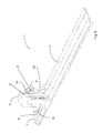
Fig 5 is a schematic perspective view obliquely from the back of an embodiment of a feeder device of the present invention. -
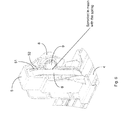
Fig 6 is a magnification of the sled infig 5 . -
Fig 7 is a schematic perspective view obliquely from the back of an embodiment of a feeder device of the present invention with the damper removed. -
Fig 8 is a schematic exploded perspective view obliquely from the back of an embodiment of a feeder device of the present invention. - Embodiments will now be described more fully hereinafter and with reference to the accompanying drawings, in which certain embodiments are shown. However, other embodiments in many different forms are possible within the scope of the present disclosure. Rather, the following embodiments are provided by way of example so that this disclosure will be thorough and complete, and will fully convey the scope of the disclosure to those skilled in the art. Like numbers refer to like elements throughout the description.
- The elongated guide member has as a main function to guide the sled in a longitudinal direction along the guide member. The sled may be connected to the guide member by gravity in combination with a longitudinal ledge, flange or other protrusion of the guide member against which the sled can abut and be guided by. However it may be convenient to provide the sled with a fastening means by which the sled can reach around to the underside of longitudinal sides or side flanges of the guide member to be more securely connected to the guide member and not rely on gravity for staying connected thereto.
- The sled may be slidably connected to the guide member by being able to slide on respective sliding surfaces e.g. rails of the sled and guide member, or slide enhancing means such as rolls or the like may be provided on the sled and/or on the guide member for facilitating the sliding of the sled in relation to the guide member. Any sliding surfaces of the sled and/or guide member may be provided with slide enhancing material e.g. in the form of a strip or tape.
- When a product or products are discussed herein, this is intended to refer to a product item or several product items, not necessarily to different types of products.
- When a longitudinal direction is mentioned herein, a direction which is parallel to a longitudinal axis of the elongated guide member is intended.
- That the products are successive implies that they form a longitudinal queue along the guide member.
- In some embodiments, the damper is a rotary damper. A rotary damper may be convenient since it may be mounted on the sled and provide damping for a sliding motion along essentially the whole guide member, whereas e.g. a gas damper, which is also contemplated, due to its telescopic structure may only be able to provide damping over a part of the guide member. The rotary damper may comprise a sprocket configured for being in mesh with e.g. the spring. Such a sprocket may alternatively be called e.g. gear, pinion or cogwheel. The sprocket may be in mesh with a for that purpose arranged structure or track on the spring. In some embodiments, e.g., the spring comprises a plurality of longitudinally aligned recesses or holes (blind or through holes) configured for meshing with the sprocket of the rotary damper. The recesses or holes are longitudinally aligned such that they form a longitudinal track which is adapted to engage the sprocket as the sled to which the damper is connected slides along the guide member. In some embodiments, the track of holes along the spring may extend past a longitudinal side edge of the spring, forming a (saw) toothed longitudinal side edge with which the sprocket may mesh.
- In some embodiments, the spring is a spiral spring which is, at one of its ends, fastened or otherwise attached to a roll arranged in or otherwise connected to the sled. The spring is thus wound or rolled up onto (around) the roll when the sled is pushed forward along the guide member, and wound off said roll when the sled is pushed back e.g. when the feeder device is loaded with more products. In some embodiments, the damper is a rotary damper comprising a sprocket. The roll may then be hollow and configured to allow the sprocket to extend axially into and in mesh with said roll such that the rotational axis of the roll is essentially the same as the rotational axis of the sprocket. An inside surface of the roll may then have a structure which is adapted to the sprocket, e.g. a negative version of the sprocket surface. The sprocket may then be inserted into the hollow roll (round cylinder) along the rotational axis of the roll and mesh with the roll via its inside surface structure. The sprocket is then engaging the spring via the roll. The roll may be regarded as part of the rotary damper, engaging the spring rolled up around it.
- In some embodiments, the damper is a unidirectional damper which provides more damping action to the sliding motion of the sled towards the front end of the guide member than to a sliding motion of the sled in the opposite direction. This may be advantageous since it allows products to be slowly successively fed forward to the from of the shelf when a product is picked from the feeder device, but at the same time allows the sled to be faster slided backwards away from the shelf front when one or more products are introduced or put back into the feeder device e.g. when store personnel are loading the feeder device. The feeder device may thus be more efficiently loaded. Unidirectional dampers are known in other fields of technology, and unidirectional damping of a rotary damper may e.g. be achieved by means of a rotor in a viscous fluid, e.g. in accordance with
patent document EP 2 348 228 .EP 2 348 228 - In some embodiments, the sled comprises opposing longitudinally extending grooves engaging longitudinal sides of the guide member, whereby the sled is slidably connected to the guide member. The grooves are longitudinal such as they are parallel to a longitudinal axis of the guide member. Such grooves or tracks which may be integrally formed in the sled may be a convenient means of connecting the sled slidably to the guide member. For instance, the sled may be slided onto an essentially flat guide member at an end of the guide member, with the longitudinal grooves enveloping (e.g. gripping/extending around) the longitudinal sides of the flat guide member but still allowing the sled to slide along the guide member.
- In some embodiments, the spring has two ends and is at one of its ends attached to the sled and at the other one of its ends attached to the guide member at the front end of said guide member. I may be convenient to attach the spring to the sled to achieve a robust construction of the device. Alternatively, the end of the spring may lay against and push on the sled without being attached/fixed to the sled. The spring may e.g. be a spiral spring or a helical spring.
- In some embodiments, the feeder device further comprises a housing configured for, in cooperation with the shelf, enclosing the successive products longitudinally along at least a part of the guide member, the housing having an opening at the front end of the guide member for allowing access to a front-most product of the successive products. The housing may enclose the products along three longitudinal sides (above and to each lateral side of the queue of successive products in the device), again referring to a longitudinal axis of the guide member. Below, the products are enclosed by the shelf when the device is mounted thereon. Enclosing the products thus, prevents access to products in the feeder device. For allowing access to the front-most product, the housing has an opening allowing e.g. a customer to pick out said front-most product. The housing thus makes it impossible or at least more difficult for someone (possibly a thief) to access and remove many or all of the products at the same time. Instead, it is necessary to wait until the next product is fed forward to the front end of the guide member until picking it, i.e. removing it from the feeder device. The lateral sides of the housing may also function as side barriers for keeping the queued products in line. The housing is thus an alternative to shelf dividing barriers, which may alternatively be used with the present invention. The housing dimensions may conveniently be adapted to the size of the products therein. The opening is conveniently designed so as to only provide easy external access to one product item at the time. The housing may be made from a transparent material, e.g. transparent plastics, in order to allow the products therein to be seen even though they are not directly accessible. In some embodiments, the housing comprises a front barrier at the front end of the guide member. The barrier is configured for stopping the front-most product of the successive products from being pushed beyond the front of the shelf. In other embodiments, a front barrier is not part of the housing or even of the feeder device, but may be provided as part of the shelf at the front of said shelf. The spring thus pushes the queued products, via the sled, against the front barrier. The housing may also comprise a backside, preventing access to the products from the back of the shelf. The housing may be attached to the guide member, or the housing may be configured to be attached only to the shelf.
- In some embodiments, the feeder device is mounted on the shelf. However, the present invention also relates to a feeder device which is configured to be mounted/attached to a shelf, but which is currently not so mounted/attached.
-
Figure 1 illustrates an embodiment of afeeder device 1 of the present invention, mounted onto ashelf 2. - A flat
elongated guide member 4 lays on top of theshelf 2 and extends from thefront 3 of theshelf 2 and backwards atop the shelf surface, with thefront end 7 of the guide member being positioned at thefront 3 of theshelf 2. The guide member may e.g. be mounted to the shelf by means of a fastening means of a screw, clip or similar. Theguide member 4 is provided with longitudinally alignedrecesses 10 in the form of through holes which form a longitudinal ladder-type track at and along alongitudinal side 12 of the guide means. - A
sled 5 is slidably arranged on theguide member 4. In thesled 5, arotary damper 8 is attached to the sled. Thedamper 8 comprises asprocket 9 which protrudes somewhat below thesled 5 and is there in mesh with the track ofholes 10 of theguide member 4. As thesled 5 moves forward or backward along theguide member 4, the track ofholes 10 engages the sprocket to turn said sprocket. Additionally or alternatively, the sprocket is engaging the spring in accordance with the present invention. The turning motion of the sprocket is dampened, at least in the forward direction of thesled 5, whereby therotary damper 8 by means of thesprocket 9 dampens the forward sliding motion of thesled 5. The damper may e.g. prolong the time for feeding the next product item to a front barrier after a previous front-most product item has been removed from the feeder device to more than 3 seconds, such as more than 5 seconds or more than 10 seconds, depending e.g. on the thickness of the products. Aspiral spring 6 is mounted in and attached to thesled 5, with an external end of thespring 6 being attached to thefront end 7 of theguide member 4. Thespring 6 is configured to push thesled 5 forward towards thefront end 7 and thefront 3 of theshelf 2. - A
housing 13 made from a transparent plastic material is positioned on the top surface of theshelf 2 and encloses theguide member 4. The housing may enclose the products along three longitudinal sides (above and to each lateral side of the queue of successive products in the device), again referring to a longitudinal axis of the guide member. Below, the products are enclosed by the shelf when the device is mounted thereon. The housing may be attached to the guide member, and indirectly attached to theshelf 2 via theguide member 4, or it may be directly attached to the shelf e.g. by means of a fastening means of a screw, clip or similar. If thehousing 13 is attached both to theshelf 2 and theguide member 4, the guide member is indirectly attached to the shelf via the housing. Thehousing 13 has anopening 14 which is adapted to allow easy access to (only) the front-most product of the queued product items covered by the housing. The housing also comprises afront barrier 15, in the embodiment of the figure divided into a left and a right part with a space there between to further improve accessibility to the front-most product. Further, thehousing 13 may comprise longitudinal bottom sections configured to lay flat on top of theshelf 2, essentially in the same plane as theguide member 4. The top surfaces of these bottom sections may be configured to support the queuing products such that they rest on top of the sections and slides along the sections when the products are pushed forward by the sled. The sections may e.g. sliding enhancing strips ortape 16 applied to them to improve the sliding of the products thereon. -
Figure 2 illustrates an embodiment of afeeder device 1 of the present invention, not mounted onto ashelf 2. - The figure shows the
feeder device 1 as infigure 1 but without theoptional housing 13 and not mounted to theshelf 2. The discussions above in relation tofigure 1 regarding theguide member 4, thesled 5, thedamper 8 and thespring 6 are also relevant for thedevice 1 offigure 2 . - As is seen in more detail in
figure 2 than infigure 1 , thesled 5 comprises a relatively flatupright section 17 extending perpendicular to the longitudinal extension of theguide member 4. Thisupright section 17 is adapted for contacting and pushing against a backside of the back-most product item in the feeder device, thus pushing all the successive products forward. Further, fastening means 18, in the figures illustrated as holes, in the guide member are provided for mounting the feeder device on ashelf 2.Figure 2 also provides a better view of how thesled 5 is slidably connected to theguide member 4 by extending around the longitudinal side edges 12 of the guide member by means oflongitudinal grooves 11 formed in the bottom part of thesled 5. - The
feeding device 1 offigure 2 may be combined with ahousing 13 to obtain a similar embodiment as infigure 1 , or it may be used without a housing. -
Figure 3 shows an embodiment of thesled 5 from behind, and particularly shows how therotary damper 8 may be mounted in the sled e.g. for engaging the spring (6) and/or the guide member. Thelongitudinal grooves 11 are shown more clearly and from behind. Thesprocket 9 of thedamper 8 protrudes from the bottom, i.e. under side, of thesled 5, allowing it to access theguide member 4 to mesh herewith when the sled is slidably connected to said guide member. -
Figure 4 shows an embodiment of the feeder device loaded withproducts 100. In the figure, foursuccessive products 100a-d are shown, but any number of products may be used. Thefront-most product 100a is accessible through theopening 14 in thehousing 13. When e.g. a customer picks thefront-most product 100a and thus removes it from the feeder device, thespring 6, via thesled 5, pushes the remainingproducts 100b-d forward, as discussed above. Thesled 5, e.g. by means of itsflat upright section 17, is in contact with the back side of theback-most product 100d as it pushes theproducts 100 forward. -
Figures 5 and6 illustrate an embodiment of afeeder device 1 of the present invention, not mounted onto ashelf 2, where the spring attached to thesled 5 is not engaging theguide member 4, but only engages thespring 6. The embodiment offigure 5 differs from the embodiments of the previous figures in that it is shown how thesprocket 9 of the damper is in mesh with thespring 6. Thespring 6 is provided with a track of longitudinally aligned throughholes 51 adapted to fit and mesh with the cogs of thesprocket 9. Thus, thedamper 8 can dampen the movement of thesled 5 by being in mesh with thespring 6. Thespring 6 is at one (external) end fastened to the front of the guide member, and at the other (internal) end rolled up onto a roll in thesled 5. Thesprocket 9 is in mesh with thespring 6 and dampens/regulates the speed with which the spring can roll (wind) itself up onto the roll. Such a roll in combination with a spiral spring can be used with any of the embodiments of the preceding figures as well. In some embodiments, the track ofholes 51 along thespring 6 may extend past alongitudinal side edge 52 of the spring, forming a (saw) toothedlongitudinal side edge 52 with which thesprocket 9 may mesh. In the embodiment offigures 5 and6 , thesprocket 9 is positioned in mesh with the outside of the spring, in relation to the rolled-up spring around the roll. This may be advantageous since the stiffness of thespring 6 then naturally presses the spring against thesprocket 9 as it passes said sprocket. However, in some other embodiments, it may be convenient to position the sprocket in mesh with the inside of thespring 6. -
Figure 7 further illustrates how thespring 6 may be rolled-up onto aroll 71 in thesled 5 in embodiments of thefeeder device 1. The figure also shows how theroll 71 may be hollow and have an inner surface with a structure adapted to receive asprocket 9 of adamper 8. On thesled 5, by thehollow roll 71, twopins 72 are present for fastening adamper 8 to thesled 5 such that asprocket 9 is inserted into thehollow roll 71 to mesh with said roll via its inner surface structure. -
Figure 8 is an exploded perspective view of an embodiment of thefeeder device 1 of the present invention. Thespring 6 is a spiral spring with one of its ends fastened at thefront 7 of theguide member 4. The other (inner) end of thespring 6 is fastened to aroll 71 onto which the spring is partly rolled-up. Theroll 71 and the part of thespring 6 rolled-up thereon is positioned inside thesled 5. Adamper 8 is mounted to thesled 5 by means of the twopins 72 on the sled. In the more specific embodiment illustrated infigure 8 , theroll 71 is a hollow round cylinder having an inside surface with a structure adapted to mesh with asprocket 9 of thedamper 8 when the damper is mounted to thesled 5, as discussed above e.g. with reference tofigure 7 . - Although not specifically shown in
figure 8 , thesled 5 is slidably attached to theguide member 4 as discussed above. - By embodiments of the feeder device of the present invention, as exemplified in the figures, a theft preventing anti-sweep system for displaying
products 100 on ashelf 2, e.g. products attractive to thieves, particularly relatively small and expensive articles such as razor blades or batteries, is obtained. This is according to the present invention achieved by means of the dampened feeder or pushing mechanism discussed herein. Since it will take some time for the next article to be pushed in place for easy picking, e.g. 5-10 seconds, a potential thief will abstain from stealing, at least from stealing many items at the same time from thesame feeder device 1, since he needs to pick the items one-by-one and wait 5-10 s between each item. It may also be possible to adjust the time for feeding thenext product 100 to theshelf front 3 by adjusting the tension of thespring 6 and/or the strength of thedamper 8. Thefeeder device 1 may additionally comprise ahousing 13, which further prevents a thief from accessing more than thefront-most product 100a in the feeder device. The housing is essentially a box which covers the left, right and top sides of the feeder device when mounted on ashelf 2. If desired, also the back side of the feeder device may be covered by the housing. Conveniently, the dimensions of thehousing 13 is adapted to the dimensions of the products intended to be queued therein, such that only the front-most of thesuccessive products 100 is accessible through theopening 14 of the housing, when thefront-most product 100a has been pushed to the front of thefeeder device 1, typically the front of theshelf 2 and against thefront barrier 15. Thehousing 13 may have any suitable shape but is typically cylindrical (e.g. with a round or rectangular cross-section) to fit the shape and size of theproducts 100. The housing may e.g. be extruded and/or it may be composed of several parts which are fitted together or be monolithic. The housing may in some embodiments also comprise shelf dividers of theshelf 2. - Additionally, embodiments of the present invention may facilitate putting back a picked product to the correct place on a shelf. A person may e.g. like to pick and briefly examine a plurality of different products of different brands or different colours or the like, before possibly choosing one to by buy, putting the other products back on the shelf. By the damping of the
feeder device 1, a product may be more easily put back in the same place as it was picked from since it takes a few seconds or more before the next product has been feed forward to the front of the feeder device. This reduces the risk of the person putting the product back in the wrong place. - According to another aspect of the present invention, there is provided a feeder device, which feeder device is configured for being mounted on a shelf for feeding successive products to a front of the shelf. The shelf may e.g. be a shelf in a shop such as a grocery store or department store or the like. The feeder device comprises an elongated guide member which is configured for extending longitudinally backwards from the front of the shelf when the device is mounted. The feeder device also comprises a sled which is slidably connected to the guide member such that the sled can slide along the length of the elongated guide member. The sled is configured for engaging a back-most product of the successive products for pushing the products towards the front of the shelf. The feeder device also comprises a spring connected to the sled (e.g. engaging or being attached to the sled), and configured for pushing the sled along the guide member towards a front end of said guide member. The feeder device further comprises a damper connected to the sled, and configured for damping the sliding motion of the sled towards the front end of the guiding member when the sled is pushed by the spring.
- The present disclosure has mainly been described above with reference to a few embodiments. However, as is readily appreciated by a person skilled in the art, other embodiments than the ones disclosed above are equally possible within the scope of the present disclosure, as defined by the appended patent claims.
Claims (12)
- A feeder device (1) configured for mounting on a shelf for feeding successive products (100) to a front (3) of the shelf (2), the device comprising:an elongated guide member (4) which is configured for extending longitudinally backwards from the front (3) of the shelf (2) when the device (1) is mounted;a sled (5) slidably connected to the guide member (4) such that the sled can slide along the length of the elongated guide member, configured for engaging a back-most product (100d) of the successive products for pushing the products towards the front (3) of the shelf (2); anda spring (6) connected to the sled (5), and configured for pushing the sled along the guide member (4) towards a front end (7) of said guide member;characterised by further comprising:a damper (8) connected to the sled (5), and engaging the spring (6) for damping the sliding motion of the sled when pushed by the spring (6).
- The device of claim 1, wherein the damper (8) is a rotary damper comprising a sprocket (9) in mesh with the spring (6).
- The device of claim 2, wherein the spring (6) comprises a plurality of longitudinally aligned holes (51) configured for meshing with the sprocket (9) of the rotary damper (8).
- The device of claim 2, wherein the spring (6) has a toothed longitudinal side edge (52) configured for meshing with the sprocket (9) of the rotary damper (8).
- The device of claim 1, wherein the sled (5) comprises a roll (71), and the spring (6) is a spiral spring which is, at one of its ends, rolled-up around said roll (71), and wherein the damper (8) is a rotary damper comprising a sprocket (9) extending axially into and in mesh with said roll (71) such that the rotational axis of the roll is essentially the same as the rotational axis of the sprocket (9).
- The device of any preceding claim, wherein the damper (8) is a unidirectional damper which provides more damping action to the sliding motion of the sled (5) towards the front end (7) of the guide member (4) than to a sliding motion of the sled (5) in the opposite direction.
- The device of any preceding claim, wherein the sled (5) comprises opposing longitudinally extending grooves (11) engaging longitudinal sides (12) of the guide member (4), whereby the sled (5) is slidably connected to the guide member (4).
- The device of any preceding claim, wherein the spring (6) has two ends and is at one of its ends attached to the sled (5) and at the other one of its ends attached to the guide member (4) at the front end (7) of said guide member.
- The device of any preceding claim, further comprising a housing (13) configured for, in cooperation with the shelf (2), enclosing the successive products (100) longitudinally along at least a part of the guide member (4), the housing having an opening (14) at the front end (7) of the guide member (4) for allowing access to a front-most product (100a) of the successive products.
- The device of claim 8, wherein the housing (13) comprises a front barrier (15) at the front end (7) of the guide member (4), configured for stopping the front-most product (100a) of the successive products from being pushed beyond the front (3) of the shelf (2).
- The device of claim 8 or 9, wherein the housing (13) is attached to the guide member (4).
- The device of any preceding claim, wherein the feeder device (1) is mounted on the shelf (2).
Priority Applications (1)
| Application Number | Priority Date | Filing Date | Title |
|---|---|---|---|
| EP13163994.0A EP2767192A1 (en) | 2013-02-15 | 2013-04-16 | Feeder device for presenting products on a shelf |
Applications Claiming Priority (2)
| Application Number | Priority Date | Filing Date | Title |
|---|---|---|---|
| EP13155446.1A EP2767191A1 (en) | 2013-02-15 | 2013-02-15 | Feeder device for presenting products on a shelf |
| EP13163994.0A EP2767192A1 (en) | 2013-02-15 | 2013-04-16 | Feeder device for presenting products on a shelf |
Publications (1)
| Publication Number | Publication Date |
|---|---|
| EP2767192A1 true EP2767192A1 (en) | 2014-08-20 |
Family
ID=47720414
Family Applications (2)
| Application Number | Title | Priority Date | Filing Date |
|---|---|---|---|
| EP13155446.1A Withdrawn EP2767191A1 (en) | 2013-02-15 | 2013-02-15 | Feeder device for presenting products on a shelf |
| EP13163994.0A Withdrawn EP2767192A1 (en) | 2013-02-15 | 2013-04-16 | Feeder device for presenting products on a shelf |
Family Applications Before (1)
| Application Number | Title | Priority Date | Filing Date |
|---|---|---|---|
| EP13155446.1A Withdrawn EP2767191A1 (en) | 2013-02-15 | 2013-02-15 | Feeder device for presenting products on a shelf |
Country Status (1)
| Country | Link |
|---|---|
| EP (2) | EP2767191A1 (en) |
Cited By (9)
| Publication number | Priority date | Publication date | Assignee | Title |
|---|---|---|---|---|
| WO2014198839A1 (en) | 2013-06-12 | 2014-12-18 | Pos Tuning Udo Vosshenrich Gmbh & Co. Kg | Device for advancing goods |
| WO2016120611A3 (en) * | 2015-01-28 | 2016-09-22 | The Heartbeat Manufacturing Co (Redditch) Limited | Shelf management device |
| CN107405010A (en) * | 2015-03-12 | 2017-11-28 | 哈特比特制造(雷迪奇)有限公司 | Shelf management device |
| USD836954S1 (en) | 2016-03-02 | 2019-01-01 | Retail Space Solutions Llc | Shelf components |
| USD843760S1 (en) | 2016-03-02 | 2019-03-26 | Dci Marketing, Inc. | Shelf components |
| USD856040S1 (en) | 2016-09-12 | 2019-08-13 | Retail Space Solutions Llc | Merchandiser parts |
| US11064817B2 (en) | 2015-07-23 | 2021-07-20 | Retail Space Solutions Llc | Merchandiser and methods relating to same |
| US20240188730A1 (en) * | 2022-06-15 | 2024-06-13 | Dongguan Yongsheng Spring Co., Ltd. | Goods Propulsion Apparatus With A Reducer |
| EP4578342A3 (en) * | 2018-03-21 | 2025-09-03 | Fasteners for Retail, Inc. | Retail merchandise pusher with remote alarm feature |
Families Citing this family (1)
| Publication number | Priority date | Publication date | Assignee | Title |
|---|---|---|---|---|
| US11363894B2 (en) * | 2019-04-05 | 2022-06-21 | Fasteners For Retail, Inc. | Anti-theft pusher with incremental distance detection |
Citations (5)
| Publication number | Priority date | Publication date | Assignee | Title |
|---|---|---|---|---|
| DE1297833B (en) * | 1966-08-25 | 1969-06-19 | Sofimetal Soc Finaciere Metall | Device for holding and advancing a stack of goods and display packs or the like. |
| EP0337340A2 (en) | 1988-04-11 | 1989-10-18 | Rtc Industries, Inc. | Spring-urged shelf divider system |
| GB2386116A (en) * | 2002-03-06 | 2003-09-10 | Gillette Co | Product dispenser |
| EP1806076A2 (en) | 2005-08-30 | 2007-07-11 | Kesslers International Limited | Pusher apparatus |
| EP2348228A1 (en) | 2008-11-20 | 2011-07-27 | Oiles Corporation | Rotary damper |
Family Cites Families (3)
| Publication number | Priority date | Publication date | Assignee | Title |
|---|---|---|---|---|
| US8215520B2 (en) * | 2003-10-17 | 2012-07-10 | Rock-Tenn Shared Services, Llc | Secure merchandising system |
| US20100059469A1 (en) * | 2008-09-05 | 2010-03-11 | Jeffrey Mason | Display device with slow product advancing mechanism |
| WO2010141552A2 (en) * | 2009-06-02 | 2010-12-09 | Rock-Tenn Shared Services, Llc | Time delay product pushing system |
-
2013
- 2013-02-15 EP EP13155446.1A patent/EP2767191A1/en not_active Withdrawn
- 2013-04-16 EP EP13163994.0A patent/EP2767192A1/en not_active Withdrawn
Patent Citations (5)
| Publication number | Priority date | Publication date | Assignee | Title |
|---|---|---|---|---|
| DE1297833B (en) * | 1966-08-25 | 1969-06-19 | Sofimetal Soc Finaciere Metall | Device for holding and advancing a stack of goods and display packs or the like. |
| EP0337340A2 (en) | 1988-04-11 | 1989-10-18 | Rtc Industries, Inc. | Spring-urged shelf divider system |
| GB2386116A (en) * | 2002-03-06 | 2003-09-10 | Gillette Co | Product dispenser |
| EP1806076A2 (en) | 2005-08-30 | 2007-07-11 | Kesslers International Limited | Pusher apparatus |
| EP2348228A1 (en) | 2008-11-20 | 2011-07-27 | Oiles Corporation | Rotary damper |
Cited By (15)
| Publication number | Priority date | Publication date | Assignee | Title |
|---|---|---|---|---|
| WO2014198839A1 (en) | 2013-06-12 | 2014-12-18 | Pos Tuning Udo Vosshenrich Gmbh & Co. Kg | Device for advancing goods |
| EP3007592B1 (en) * | 2013-06-12 | 2018-08-08 | POS TUNING Udo Voßhenrich GmbH & Co. KG | Arrangement comprising a device for advancing goods and goods |
| WO2016120611A3 (en) * | 2015-01-28 | 2016-09-22 | The Heartbeat Manufacturing Co (Redditch) Limited | Shelf management device |
| US10172482B2 (en) | 2015-01-28 | 2019-01-08 | The Heartbeat Manufacturing Co (Redditch) Limited | Shelf management device |
| CN107405010A (en) * | 2015-03-12 | 2017-11-28 | 哈特比特制造(雷迪奇)有限公司 | Shelf management device |
| US11064817B2 (en) | 2015-07-23 | 2021-07-20 | Retail Space Solutions Llc | Merchandiser and methods relating to same |
| USD843760S1 (en) | 2016-03-02 | 2019-03-26 | Dci Marketing, Inc. | Shelf components |
| USD867797S1 (en) | 2016-03-02 | 2019-11-26 | Retail Space Solutions Llc | Shelf components |
| USD879521S1 (en) | 2016-03-02 | 2020-03-31 | Retail Space Solutions Llc | Shelf components |
| USD879522S1 (en) | 2016-03-02 | 2020-03-31 | Retail Space Solutions Llc | Shelf components |
| USD836954S1 (en) | 2016-03-02 | 2019-01-01 | Retail Space Solutions Llc | Shelf components |
| USD856040S1 (en) | 2016-09-12 | 2019-08-13 | Retail Space Solutions Llc | Merchandiser parts |
| EP4578342A3 (en) * | 2018-03-21 | 2025-09-03 | Fasteners for Retail, Inc. | Retail merchandise pusher with remote alarm feature |
| US20240188730A1 (en) * | 2022-06-15 | 2024-06-13 | Dongguan Yongsheng Spring Co., Ltd. | Goods Propulsion Apparatus With A Reducer |
| US12329295B2 (en) * | 2023-06-15 | 2025-06-17 | Dongguan Yongsheng Spring Co., Ltd. | Goods propulsion apparatus with a reducer |
Also Published As
| Publication number | Publication date |
|---|---|
| EP2767191A1 (en) | 2014-08-20 |
Similar Documents
| Publication | Publication Date | Title |
|---|---|---|
| EP2767191A1 (en) | Feeder device for presenting products on a shelf | |
| US6923330B1 (en) | Pull strip actuated pusher for merchandise displays | |
| US9101231B2 (en) | Freezer pusher | |
| US9101230B2 (en) | Salad pusher | |
| US7497342B2 (en) | Product management display system | |
| US11064818B2 (en) | Quick-load merchandising pusher systems and methods for dividing, pushing and/or dispensing one or more retail products | |
| US20150068991A1 (en) | Retail merchandise pusher | |
| EP0336696B1 (en) | Merchandiser assembly | |
| US6523703B1 (en) | Pusher mechanism for a merchandising display shelf | |
| US5012936A (en) | Merchandiser assembly | |
| RU2664379C2 (en) | Goods feeding device | |
| US20030057167A1 (en) | Merchandising system | |
| US20030061973A1 (en) | Product display and fronting assembly | |
| EP1779749A1 (en) | Shelf unit | |
| US20070272634A1 (en) | Well Merchandiser | |
| US20090223916A1 (en) | Extendable product shelving | |
| CA2768320C (en) | Goods feeding system for receiving and presenting goods | |
| US20160286983A1 (en) | Feed device for the automatic shifting of objects by means of a guide element, construction set, and method for mounting a feed device | |
| EP2944229A1 (en) | Shelf assembly | |
| EP3391788B1 (en) | Feeder device for presenting products on a shelf | |
| WO2001017404A1 (en) | A dispensing apparatus | |
| EP2599407B1 (en) | A cabinet for tobacconists' and similar retail shops. | |
| RU202219U1 (en) | Pusher for packs | |
| CA1308068C (en) | Merchandiser assembly and package therefor | |
| EP3305137B1 (en) | Shelf management system |
Legal Events
| Date | Code | Title | Description |
|---|---|---|---|
| PUAI | Public reference made under article 153(3) epc to a published international application that has entered the european phase |
Free format text: ORIGINAL CODE: 0009012 |
|
| 17P | Request for examination filed |
Effective date: 20130416 |
|
| AK | Designated contracting states |
Kind code of ref document: A1 Designated state(s): AL AT BE BG CH CY CZ DE DK EE ES FI FR GB GR HR HU IE IS IT LI LT LU LV MC MK MT NL NO PL PT RO RS SE SI SK SM TR |
|
| AX | Request for extension of the european patent |
Extension state: BA ME |
|
| STAA | Information on the status of an ep patent application or granted ep patent |
Free format text: STATUS: THE APPLICATION IS DEEMED TO BE WITHDRAWN |
|
| 18D | Application deemed to be withdrawn |
Effective date: 20150221 |