EP2766966B1 - Cable holder - Google Patents
Cable holder Download PDFInfo
- Publication number
- EP2766966B1 EP2766966B1 EP12784126.0A EP12784126A EP2766966B1 EP 2766966 B1 EP2766966 B1 EP 2766966B1 EP 12784126 A EP12784126 A EP 12784126A EP 2766966 B1 EP2766966 B1 EP 2766966B1
- Authority
- EP
- European Patent Office
- Prior art keywords
- cable holder
- trays
- canopy
- clip
- hanger
- Prior art date
- Legal status (The legal status is an assumption and is not a legal conclusion. Google has not performed a legal analysis and makes no representation as to the accuracy of the status listed.)
- Not-in-force
Links
Images




Classifications
-
- F—MECHANICAL ENGINEERING; LIGHTING; HEATING; WEAPONS; BLASTING
- F16—ENGINEERING ELEMENTS AND UNITS; GENERAL MEASURES FOR PRODUCING AND MAINTAINING EFFECTIVE FUNCTIONING OF MACHINES OR INSTALLATIONS; THERMAL INSULATION IN GENERAL
- F16L—PIPES; JOINTS OR FITTINGS FOR PIPES; SUPPORTS FOR PIPES, CABLES OR PROTECTIVE TUBING; MEANS FOR THERMAL INSULATION IN GENERAL
- F16L3/00—Supports for pipes, cables or protective tubing, e.g. hangers, holders, clamps, cleats, clips, brackets
- F16L3/22—Supports for pipes, cables or protective tubing, e.g. hangers, holders, clamps, cleats, clips, brackets specially adapted for supporting a number of parallel pipes at intervals
- F16L3/223—Supports for pipes, cables or protective tubing, e.g. hangers, holders, clamps, cleats, clips, brackets specially adapted for supporting a number of parallel pipes at intervals each support having one transverse base for supporting the pipes
- F16L3/2235—Supports for pipes, cables or protective tubing, e.g. hangers, holders, clamps, cleats, clips, brackets specially adapted for supporting a number of parallel pipes at intervals each support having one transverse base for supporting the pipes each pipe being supported by a common element fastened to the base
-
- H—ELECTRICITY
- H02—GENERATION; CONVERSION OR DISTRIBUTION OF ELECTRIC POWER
- H02G—INSTALLATION OF ELECTRIC CABLES OR LINES, OR OF COMBINED OPTICAL AND ELECTRIC CABLES OR LINES
- H02G3/00—Installations of electric cables or lines or protective tubing therefor in or on buildings, equivalent structures or vehicles
- H02G3/30—Installations of cables or lines on walls, floors or ceilings
-
- F—MECHANICAL ENGINEERING; LIGHTING; HEATING; WEAPONS; BLASTING
- F16—ENGINEERING ELEMENTS AND UNITS; GENERAL MEASURES FOR PRODUCING AND MAINTAINING EFFECTIVE FUNCTIONING OF MACHINES OR INSTALLATIONS; THERMAL INSULATION IN GENERAL
- F16L—PIPES; JOINTS OR FITTINGS FOR PIPES; SUPPORTS FOR PIPES, CABLES OR PROTECTIVE TUBING; MEANS FOR THERMAL INSULATION IN GENERAL
- F16L3/00—Supports for pipes, cables or protective tubing, e.g. hangers, holders, clamps, cleats, clips, brackets
- F16L3/08—Supports for pipes, cables or protective tubing, e.g. hangers, holders, clamps, cleats, clips, brackets substantially surrounding the pipe, cable or protective tubing
- F16L3/12—Supports for pipes, cables or protective tubing, e.g. hangers, holders, clamps, cleats, clips, brackets substantially surrounding the pipe, cable or protective tubing comprising a member substantially surrounding the pipe, cable or protective tubing
- F16L3/123—Supports for pipes, cables or protective tubing, e.g. hangers, holders, clamps, cleats, clips, brackets substantially surrounding the pipe, cable or protective tubing comprising a member substantially surrounding the pipe, cable or protective tubing and extending along the attachment surface
-
- F—MECHANICAL ENGINEERING; LIGHTING; HEATING; WEAPONS; BLASTING
- F16—ENGINEERING ELEMENTS AND UNITS; GENERAL MEASURES FOR PRODUCING AND MAINTAINING EFFECTIVE FUNCTIONING OF MACHINES OR INSTALLATIONS; THERMAL INSULATION IN GENERAL
- F16L—PIPES; JOINTS OR FITTINGS FOR PIPES; SUPPORTS FOR PIPES, CABLES OR PROTECTIVE TUBING; MEANS FOR THERMAL INSULATION IN GENERAL
- F16L3/00—Supports for pipes, cables or protective tubing, e.g. hangers, holders, clamps, cleats, clips, brackets
- F16L3/08—Supports for pipes, cables or protective tubing, e.g. hangers, holders, clamps, cleats, clips, brackets substantially surrounding the pipe, cable or protective tubing
- F16L3/12—Supports for pipes, cables or protective tubing, e.g. hangers, holders, clamps, cleats, clips, brackets substantially surrounding the pipe, cable or protective tubing comprising a member substantially surrounding the pipe, cable or protective tubing
- F16L3/13—Supports for pipes, cables or protective tubing, e.g. hangers, holders, clamps, cleats, clips, brackets substantially surrounding the pipe, cable or protective tubing comprising a member substantially surrounding the pipe, cable or protective tubing and engaging it by snap action
-
- F—MECHANICAL ENGINEERING; LIGHTING; HEATING; WEAPONS; BLASTING
- F16—ENGINEERING ELEMENTS AND UNITS; GENERAL MEASURES FOR PRODUCING AND MAINTAINING EFFECTIVE FUNCTIONING OF MACHINES OR INSTALLATIONS; THERMAL INSULATION IN GENERAL
- F16M—FRAMES, CASINGS OR BEDS OF ENGINES, MACHINES OR APPARATUS, NOT SPECIFIC TO ENGINES, MACHINES OR APPARATUS PROVIDED FOR ELSEWHERE; STANDS; SUPPORTS
- F16M13/00—Other supports for positioning apparatus or articles; Means for steadying hand-held apparatus or articles
- F16M13/02—Other supports for positioning apparatus or articles; Means for steadying hand-held apparatus or articles for supporting on, or attaching to, an object, e.g. tree, gate, window-frame, cycle
- F16M13/022—Other supports for positioning apparatus or articles; Means for steadying hand-held apparatus or articles for supporting on, or attaching to, an object, e.g. tree, gate, window-frame, cycle repositionable
Definitions
- the present invention relates to a cable holder, and, more particularly, to a cable holder adapted to secure a plurality of cables.
- Cable holders organize and support wires and cables in various settings and locations.
- cable holders may include mechanisms that restrain motion of the cables at their points of support. Such mechanisms, however, may also provide unnecessary restraints in inserting and removing cables from the cable holder.
- the present invention overcomes the disadvantages and shortcomings discussed above by providing a cable holder having a mechanism that enables quick insertion and release of cables into and out of the cable holder, while restraining movement of the cables when installed therein.
- the cable holder comprises a frame including a hanger having a first end, a second end opposite the first end, a first side, a second side opposite the first side, and a plurality of trays extending from the first side.
- Each of the plurality of trays includes a top surface and a bottom surface opposite the top surface, the top surface of one of the plurality of trays and the bottom surface of another of the plurality of trays immediately positioned above said one of said plurality of trays forming a pocket that is sized and shaped to receive at least one cable.
- Each of the plurality of trays includes at least one low rail extending from said top surface thereof. In another embodiment, each of the plurality of trays includes a plurality of low rails. In an embodiment, at least one of the plurality of trays includes at least one high rail extending from the bottom surface thereof. In an embodiment, the plurality of trays are arranged in a column extending proximate from the first end of the hanger and proximate to the second end of the hanger. In an embodiment, one of the plurality of trays positioned proximate to the second end of said hanger does not include a high rail, while each of the remaining of the plurality of trays includes at least one high rail. According to the invention, each of the plurality of trays includes an upward lip extending therefrom.
- each of the plurality of trays is resiliently flexible such that it is moveable by depressing the upward lip.
- each of the plurality of trays includes a pair of spaced-apart, low-rails formed on a top surface thereof, and a centrally-located high-rail formed on a bottom surface thereof.
- the frame includes a canopy attached to the first end of the hanger.
- the canopy includes a bottom surface and at least one high rail extending from the bottom surface of the canopy.
- the cable holder further comprises a clip attached to the canopy, the clip being sized and shaped to attach the cable holder to a structure.
- the clip includes at least one opening
- the canopy includes a rear side and a projection extending outwardly from the rear side, the projection of the canopy being sized and shaped to receive the at least one opening of the clip.
- the clip includes a head, a leg portion extending substantially perpendicular from the head, and a back portion extending substantially perpendicular from the head, the at least one opening includes a first opening formed within the leg portion and a second opening formed within the at least back portion.
- the rear side of the canopy includes a slot, and the leg portion and back portion are positioned within the slot.
- the clip includes at least one spur.
- the canopy includes at least one tab extending outwardly from the rear side thereof for engagement with the structure.
- the canopy includes a plurality of tabs.
- the hanger includes at least one mounting hole formed therein that is sized and shaped to receive a fastener for fastening the cable holder to the structure.
- FIGS. 1 through 6E illustrate a cable holder 10 that is constructed in accordance with an embodiment of the present invention.
- the cable holder 10 can be used to support a plurality of cables used in connection with a variety of systems, it is particularly suitable for supporting cables on a bracket used in connection with an array of solar panels. Accordingly, the cable holder 10 will be described hereinafter in connection with a bracket used with an array of solar panels.
- the cable holder 10 includes a frame 12 that serves as a backbone for supporting all of the elements of the cable holder 10, which will be described hereinafter.
- the frame 12 includes a substantially T-shaped canopy 14 having a front side 16, a rear side 18 opposite the front side 16, and sides 20, 22 intermediate the front and rear sides 16, 18.
- the canopy 14 is substantially rectangular in shape. In other embodiments, the canopy 14 may have other suitable shapes.
- a ridge 23 having a slot 25 is formed on the rear side 18 of the canopy 14. In an embodiment, the ridge 23 is centrally positioned on the rear side 18 canopy 14.
- a pair of tabs 24 extends from the rear side 18 of the canopy 14, one of which is located proximate to the side 20, and the other of which is located proximate to the side 22.
- each of the pair of tabs 24 extends rearward and downwardly from the rear side 18 of the canopy 14.
- a projection 26 extends rearward from the rear side 18 of the canopy 14 and intermediate the sides 20, 22.
- the projection 26 is positioned centrally on the rear side 18 of the canopy 14.
- the cable holder 10 includes a clip 28 attached to the projection 26.
- the cable holder 10 may include a plurality of the projections 26 and a plurality of the clips 28, each of which being attached to a corresponding one of the projections 26 (not shown in the Figures).
- the structure and function of the clip 28 will be described in greater detail hereinafter.
- the frame 12 includes a hanger 30 having a first end 31 and a second end 33 opposite the first end 31, and a front side 35 and a rear side 37 opposite the front side 35.
- the canopy 14 is formed integrally with the hanger 30 at the first end 31 thereof.
- the hanger 30 supports a plurality of horizontally oriented panels 32 (see, for example, FIG. 3 ) located between the first and second ends 31, 33, and which are separated from one another by a plurality of openings 34.
- the hanger 30 includes a plurality of trays 36 (or steps), each of which is attached to an upper forward portion of a corresponding one of the plurality of panels 34 for supporting cables C therein, as shown in FIGS. 7 through 9 , which will be described hereinafter.
- the plurality of trays 36 is arranged in a column, as shown in FIGS. 1 through 5 .
- each of the plurality of trays 36 is resiliently flexible, which will be described in greater detail hereinafter.
- an upward lip 38 is formed on the front portion of each of the plurality of trays 36.
- each of the lips 38 is centrally positioned on its corresponding one of the trays 36.
- each of the trays 36 includes a plurality of the lips 38. In an embodiment, each of the lips 38 is angled in shape. In another embodiment, each of the lips 38 is curvilinear in shape. In an embodiment, each of the plurality of trays 36 includes a pair of spaced-apart, low-rails 40 formed on a top surface 41 thereof, and a centrally-located high-rail 42 formed on a bottom surface 43 thereof. In an embodiment, a high-rail 42 is not formed on the bottom surface 43 of the lowest positioned tray 36 (see FIGS. 1 , 2 and 4 ). In an embodiment, a high rail 45 is formed on the bottom of the canopy 14 (see FIGS. 1 , 2 and 4 ).
- the top surface 41 of one of the plurality of trays 36 and a bottom surface 43 of another of the plurality of trays 36 immediately positioned above the one of the plurality of trays 36 forms a pocket P that is sized and shaped to receive at least one cable C.
- the pocket P is sized and shaped to receive a plurality of the cables C.
- the hanger 30 includes a pair of mounting holes 47 formed therein to facilitate mounting of the cable holder 10 to a structure with fasteners (not shown in the Figures).
- the mounting holes 47 are positioned proximate to the second end 33 of the hanger 30.
- the hanger 30 may include more or less than the pair of mounting holes 47.
- the hanger 30 need not include the mounting holes 47.
- each of the lips 38 is pressed downwardly by a user to insert at least one cable C into the pocket P of the trays 36, as well as to remove the at least one cable C therefrom.
- the cable holder 10 includes six of the trays 36.
- the cable holder 10 may include more or less than six of the trays 36 to accommodate a desired number of the cables C.
- each of the trays 36 in combination with the positioning of the low rails 40 formed thereon and the high rails 42, 45 formed on the immediately above tray 36 or canopy 14, as appropriate, deform the contours of the cables C to form slight bends therein, which restrains the cables C from moving in the direction of the longitudinal axis of the cables C.
- the hanger 30 and the lips 38 of the trays 36 restrain the cables C from moving in the transverse direction (i.e., the direction that is oriented perpendicularly to the longitudinal axis of the cables C).
- each of the low rails 40 and the high rails 42, 45 includes a slight rounded radius so as not to pierce the cables C.
- the frame 12 may be made of NORYL® resin, nylon 6, or other suitable materials known in the art to provide the necessary flexibility required for installing and removing the cables C into and from the cable holder 10, in a manner which is described hereinbelow.
- the frame 12 may be injection molded and, therefore, fabricated in one piece to achieve a high strength-to-weight ratio and to maintain structural integrity over long periods of use.
- the clip 28 includes a head 44, a back 46, and a leg 48 with a foot 50.
- the back 46 of the clip 28 includes a pair of spurs 52 formed thereon, for purposes that are described below.
- An opening 54 is positioned within the back 46 of the clip 28, while an opening 56 is positioned within the leg 48 of the clip 28. In an embodiment, both of the openings 54, 56 are located proximate to the head 44 of the clip 28.
- the clip 28 is installed on the frame 12 of the cable holder 10 by sliding the openings 54, 56 over the projection 26 and pressing it through the opening 56 of the leg 48, thereby locking the clip 28 on the projection 26.
- portions of the head 44 and the back 46 of the clip 28 fit within the slot 25 of the ridge 23 of the canopy 14.
- the clip 28 is also maintained in position by the head 44 of the clip 28 bearing the bottom of the ridge 23, and the back 46 of the clip 28 bearing on the canopy 14.
- the clip 28 may be stamped out of 301 stainless steel.
- the clip 28 may be fabricated from other suitable materials known in the art, such as plastic.
- the cable holder 10 is shown removably fastened to a bracket 58 that supports an array of solar panels (not shown in the Figures).
- the clip 28 is slipped onto the top of the bracket 58, with the end opposite the head 44 of the clip 28 being inserted first, until the tabs 24 bear on the top of the bracket 58.
- the clip 28 is retained on the bracket 58 by the spurs 52 which provide resistance to raising the clip 28 upwardly off of the bracket 58, while the foot 50 of the clip 28 grasps a projection 60 formed on the bracket 58 (see, for example, FIG. 9 ).
- the clip 28 can secure the cable holder 10 to a wide range of sizes and profles of the bracket 58, as shown in FIGS. 7 through 9 .
- the bracket 58 is an aluminum extrusion.
- the mounting holes 47 may be used in conjunction with the clip 28, or in place of it, for receiving fasteners (e.g., bolts or screws) to attach the cable holder 10 to the bracket 58 (not shown in the Figures).
- a user may place the cables C in the trays 36 of the cable holder 10. More particularly, in an embodiment, the user depresses the lip 38 of the upper most positioned tray 36, and places one or more of the cables C in its corresponding pocket P. The user then proceeds to place one or more additional cables C in the next tray 36 (e.g., immediately below), and so on, unit the lowest most position tray 36 is filled with the cables C, as necessary depending upon the application. This sequence is utilized so that the user is always able to depress the lip 38 of one of the trays 36 without the tray 36 having the resistance of the cables C being positioned below it.
- the reverse of the installation process is utilized (i.e., the user starts removing the cables C from the lowest tray 36 first and so on).
- the installation and the removal of the cables C is accomplished by depressing the lip 38 downwardly and inserting or removing the cables C into and out of the tray 36, respectively, in one simple motion.
- the cables C can be inserted into a selected one of more of the trays 36.
- the flexibility of the trays 36 also accommodates a range of diameters of the cables C that may fit within the cable holder 10.
- the cable holder 10 may hold up to twelve of the cables C, with each of the trays 36 being sized and shaped to receive two of the cables C. Alternatively, each of the trays 36 may receive more or less than two of the cables C.
- the cable holder 10 is adapted to receive cables C each with a diameter within a range from 0.20 inch (5.2 mm) to 0.28 inch (7.2 mm). Alternatively, the cable holder 10 can receive cables C having other diameters.
- the clip 28 may be replaced with an adhesive covered pad that may be affixed to the back of the frame 12 to attach the cable holder 10 to the bracket 58.
- Other suitable mounting means known in the art to attach the cable holder 10 to the bracket 58 may be utilized. All such variations and modifications are intended to be included within the appended claims.
Landscapes
- Engineering & Computer Science (AREA)
- General Engineering & Computer Science (AREA)
- Mechanical Engineering (AREA)
- Architecture (AREA)
- Civil Engineering (AREA)
- Structural Engineering (AREA)
- Installation Of Indoor Wiring (AREA)
- Supports For Pipes And Cables (AREA)
- Clamps And Clips (AREA)
- Details Of Indoor Wiring (AREA)
Description
- This application claims the benefit of commonly-owned, co-pending
U.S. Provisional Patent Application Serial No. 61/547,369, filed Oct. 14, 2011 - The present invention relates to a cable holder, and, more particularly, to a cable holder adapted to secure a plurality of cables.
- Cable holders organize and support wires and cables in various settings and locations. In addition to providing support, cable holders may include mechanisms that restrain motion of the cables at their points of support. Such mechanisms, however, may also provide unnecessary restraints in inserting and removing cables from the cable holder.
- The document
US 2002/0136519 A1 discloses a conventional cable holder. - The present invention overcomes the disadvantages and shortcomings discussed above by providing a cable holder having a mechanism that enables quick insertion and release of cables into and out of the cable holder, while restraining movement of the cables when installed therein. The cable holder comprises a frame including a hanger having a first end, a second end opposite the first end, a first side, a second side opposite the first side, and a plurality of trays extending from the first side. Each of the plurality of trays includes a top surface and a bottom surface opposite the top surface, the top surface of one of the plurality of trays and the bottom surface of another of the plurality of trays immediately positioned above said one of said plurality of trays forming a pocket that is sized and shaped to receive at least one cable.
- Each of the plurality of trays includes at least one low rail extending from said top surface thereof. In another embodiment, each of the plurality of trays includes a plurality of low rails. In an embodiment, at least one of the plurality of trays includes at least one high rail extending from the bottom surface thereof. In an embodiment, the plurality of trays are arranged in a column extending proximate from the first end of the hanger and proximate to the second end of the hanger. In an embodiment, one of the plurality of trays positioned proximate to the second end of said hanger does not include a high rail, while each of the remaining of the plurality of trays includes at least one high rail. According to the invention, each of the plurality of trays includes an upward lip extending therefrom. According to the invention, each of the plurality of trays is resiliently flexible such that it is moveable by depressing the upward lip. According to the invention, each of the plurality of trays includes a pair of spaced-apart, low-rails formed on a top surface thereof, and a centrally-located high-rail formed on a bottom surface thereof.
- The frame includes a canopy attached to the first end of the hanger. The canopy includes a bottom surface and at least one high rail extending from the bottom surface of the canopy. The cable holder further comprises a clip attached to the canopy, the clip being sized and shaped to attach the cable holder to a structure. In an embodiment, the clip includes at least one opening, and the canopy includes a rear side and a projection extending outwardly from the rear side, the projection of the canopy being sized and shaped to receive the at least one opening of the clip. In an embodiment, the clip includes a head, a leg portion extending substantially perpendicular from the head, and a back portion extending substantially perpendicular from the head, the at least one opening includes a first opening formed within the leg portion and a second opening formed within the at least back portion. In an embodiment, the rear side of the canopy includes a slot, and the leg portion and back portion are positioned within the slot. In an embodiment, the clip includes at least one spur.
- In an embodiment, the canopy includes at least one tab extending outwardly from the rear side thereof for engagement with the structure. In another embodiment, the canopy includes a plurality of tabs. In an embodiment, the hanger includes at least one mounting hole formed therein that is sized and shaped to receive a fastener for fastening the cable holder to the structure.
- For a more complete understanding of the present invention, reference is made to the following detailed description of an exemplary embodiment considered in conjunction with the accompanying drawings, in which:
-
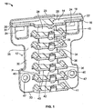
FIG. 1 is a front perspective view of a cable holder constructed in accordance with an embodiment of the present invention; -
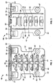
FIG. 2 is front elevational view of the cable holder shown inFIG. 1 ; -
FIG. 3 is a rear elevational view of the cable holder shown inFIG. 1 ; -
FIG. 4 is a side elevational view of the cable holder shown inFIG. 1 ; -
FIG. 5 is a top plan view of the cable holder shown inFIG. 1 ; -
FIGS. 6A through 6C are front perspective, front elevational, and side elevational views, respectively, of a clip employed by the cable holder shown inFIG. 1 ; -
FIGS. 6D and 6E are partial sectional views of the cable holder shown inFIG. 1 , with an emphasis on the clip shown inFIGS. 6A through 6C ; -
FIG. 7 is a front perspective view of the cable holder shown inFIG. 1 attached to a structure and a having a plurality of cables installed therein; and -
FIGS. 8 and 9 are front perspective and side elevational views, respectively, of the cable holder shown inFIG. 1 attached to other types of structures and having a plurality of cables installed therein. -
FIGS. 1 through 6E illustrate acable holder 10 that is constructed in accordance with an embodiment of the present invention. Although thecable holder 10 can be used to support a plurality of cables used in connection with a variety of systems, it is particularly suitable for supporting cables on a bracket used in connection with an array of solar panels. Accordingly, thecable holder 10 will be described hereinafter in connection with a bracket used with an array of solar panels. It should be understood, however, that the following description is only meant to be illustrative of the present invention and is not meant to limit the scope of the present invention, which has applicability in supporting cables or wires on brackets, cabinets, or other structures that are used with other types of systems (e.g., electrical systems, other power generating systems, telecommunication systems, etc.). - Referring to
FIGS. 1 through 5 , thecable holder 10 includes aframe 12 that serves as a backbone for supporting all of the elements of thecable holder 10, which will be described hereinafter. In an embodiment, theframe 12 includes a substantially T-shaped canopy 14 having afront side 16, arear side 18 opposite thefront side 16, andsides rear sides canopy 14 is substantially rectangular in shape. In other embodiments, thecanopy 14 may have other suitable shapes. Aridge 23 having aslot 25 is formed on therear side 18 of thecanopy 14. In an embodiment, theridge 23 is centrally positioned on therear side 18canopy 14. A pair oftabs 24 extends from therear side 18 of thecanopy 14, one of which is located proximate to theside 20, and the other of which is located proximate to theside 22. In an embodiment, each of the pair oftabs 24 extends rearward and downwardly from therear side 18 of thecanopy 14. In an embodiment, aprojection 26 extends rearward from therear side 18 of thecanopy 14 and intermediate thesides projection 26 is positioned centrally on therear side 18 of thecanopy 14. In an embodiment, thecable holder 10 includes aclip 28 attached to theprojection 26. In other embodiments, thecable holder 10 may include a plurality of theprojections 26 and a plurality of theclips 28, each of which being attached to a corresponding one of the projections 26 (not shown in the Figures). The structure and function of theclip 28 will be described in greater detail hereinafter. - Still referring to
FIGS. 1 through 5 , theframe 12 includes ahanger 30 having afirst end 31 and asecond end 33 opposite thefirst end 31, and afront side 35 and arear side 37 opposite thefront side 35. In an embodiment, thecanopy 14 is formed integrally with thehanger 30 at thefirst end 31 thereof. In an embodiment, thehanger 30 supports a plurality of horizontally oriented panels 32 (see, for example,FIG. 3 ) located between the first and second ends 31, 33, and which are separated from one another by a plurality ofopenings 34. In an embodiment, thehanger 30 includes a plurality of trays 36 (or steps), each of which is attached to an upper forward portion of a corresponding one of the plurality ofpanels 34 for supporting cables C therein, as shown inFIGS. 7 through 9 , which will be described hereinafter. In an embodiment, the plurality oftrays 36 is arranged in a column, as shown inFIGS. 1 through 5 . In an embodiment, each of the plurality oftrays 36 is resiliently flexible, which will be described in greater detail hereinafter. In an embodiment, anupward lip 38 is formed on the front portion of each of the plurality oftrays 36. In an embodiment, each of thelips 38 is centrally positioned on its corresponding one of thetrays 36. In another embodiment, each of thetrays 36 includes a plurality of thelips 38. In an embodiment, each of thelips 38 is angled in shape. In another embodiment, each of thelips 38 is curvilinear in shape. In an embodiment, each of the plurality oftrays 36 includes a pair of spaced-apart, low-rails 40 formed on atop surface 41 thereof, and a centrally-located high-rail 42 formed on abottom surface 43 thereof. In an embodiment, a high-rail 42 is not formed on thebottom surface 43 of the lowest positioned tray 36 (seeFIGS. 1 ,2 and4 ). In an embodiment, ahigh rail 45 is formed on the bottom of the canopy 14 (seeFIGS. 1 ,2 and4 ). In an embodiment, thetop surface 41 of one of the plurality oftrays 36 and abottom surface 43 of another of the plurality oftrays 36 immediately positioned above the one of the plurality oftrays 36 forms a pocket P that is sized and shaped to receive at least one cable C. In another embodiment, the pocket P is sized and shaped to receive a plurality of the cables C. - In an embodiment, the
hanger 30 includes a pair of mountingholes 47 formed therein to facilitate mounting of thecable holder 10 to a structure with fasteners (not shown in the Figures). In an embodiment, the mountingholes 47 are positioned proximate to thesecond end 33 of thehanger 30. In another embodiment, thehanger 30 may include more or less than the pair of mountingholes 47. In another embodiment, thehanger 30 need not include the mounting holes 47. - As to be described in further detail hereinafter, each of the
lips 38 is pressed downwardly by a user to insert at least one cable C into the pocket P of thetrays 36, as well as to remove the at least one cable C therefrom. In an embodiment, thecable holder 10 includes six of thetrays 36. Alternatively, in other embodiments, thecable holder 10 may include more or less than six of thetrays 36 to accommodate a desired number of the cables C. - The resiliency of each of the
trays 36, in combination with the positioning of thelow rails 40 formed thereon and thehigh rails tray 36 orcanopy 14, as appropriate, deform the contours of the cables C to form slight bends therein, which restrains the cables C from moving in the direction of the longitudinal axis of the cables C. Thehanger 30 and thelips 38 of thetrays 36 restrain the cables C from moving in the transverse direction (i.e., the direction that is oriented perpendicularly to the longitudinal axis of the cables C). In an embodiment, each of thelow rails 40 and thehigh rails - In an embodiment, the
frame 12 may be made of NORYL® resin, nylon 6, or other suitable materials known in the art to provide the necessary flexibility required for installing and removing the cables C into and from thecable holder 10, in a manner which is described hereinbelow. In an embodiment, theframe 12 may be injection molded and, therefore, fabricated in one piece to achieve a high strength-to-weight ratio and to maintain structural integrity over long periods of use. - Referring now to
FIGS. 6A through 6E , theclip 28 includes ahead 44, a back 46, and aleg 48 with afoot 50. Theback 46 of theclip 28 includes a pair ofspurs 52 formed thereon, for purposes that are described below. Anopening 54 is positioned within theback 46 of theclip 28, while anopening 56 is positioned within theleg 48 of theclip 28. In an embodiment, both of theopenings head 44 of theclip 28. Theclip 28 is installed on theframe 12 of thecable holder 10 by sliding theopenings projection 26 and pressing it through theopening 56 of theleg 48, thereby locking theclip 28 on theprojection 26. In this regard, portions of thehead 44 and theback 46 of theclip 28 fit within theslot 25 of theridge 23 of thecanopy 14. Referring specifically toFIGS. 6D and 6E , theclip 28 is also maintained in position by thehead 44 of theclip 28 bearing the bottom of theridge 23, and theback 46 of theclip 28 bearing on thecanopy 14. In an embodiment, theclip 28 may be stamped out of 301 stainless steel. Alternatively, theclip 28 may be fabricated from other suitable materials known in the art, such as plastic. - In operation, with reference to
FIGS. 7 through 9 , thecable holder 10 is shown removably fastened to abracket 58 that supports an array of solar panels (not shown in the Figures). Theclip 28 is slipped onto the top of thebracket 58, with the end opposite thehead 44 of theclip 28 being inserted first, until thetabs 24 bear on the top of thebracket 58. Theclip 28 is retained on thebracket 58 by thespurs 52 which provide resistance to raising theclip 28 upwardly off of thebracket 58, while thefoot 50 of theclip 28 grasps aprojection 60 formed on the bracket 58 (see, for example,FIG. 9 ). In an embodiment, theclip 28 can secure thecable holder 10 to a wide range of sizes and profles of thebracket 58, as shown inFIGS. 7 through 9 . In an embodiment, thebracket 58 is an aluminum extrusion. In an embodiment, the mountingholes 47 may be used in conjunction with theclip 28, or in place of it, for receiving fasteners (e.g., bolts or screws) to attach thecable holder 10 to the bracket 58 (not shown in the Figures). - With continued reference to
FIGS. 7 through 9 , once thecable holder 10 is fastened on thebracket 58, a user may place the cables C in thetrays 36 of thecable holder 10. More particularly, in an embodiment, the user depresses thelip 38 of the upper mostpositioned tray 36, and places one or more of the cables C in its corresponding pocket P. The user then proceeds to place one or more additional cables C in the next tray 36 (e.g., immediately below), and so on, unit the lowestmost position tray 36 is filled with the cables C, as necessary depending upon the application This sequence is utilized so that the user is always able to depress thelip 38 of one of thetrays 36 without thetray 36 having the resistance of the cables C being positioned below it. To remove the cables C from thecable holder 10, the reverse of the installation process is utilized (i.e., the user starts removing the cables C from thelowest tray 36 first and so on). In this manner, the installation and the removal of the cables C is accomplished by depressing thelip 38 downwardly and inserting or removing the cables C into and out of thetray 36, respectively, in one simple motion. Of course, in other embodiments, not all of thetrays 36 need be utilized, and the cables C can be inserted into a selected one of more of thetrays 36. - In an embodiment, the flexibility of the
trays 36 also accommodates a range of diameters of the cables C that may fit within thecable holder 10. In an embodiment, thecable holder 10 may hold up to twelve of the cables C, with each of thetrays 36 being sized and shaped to receive two of the cables C. Alternatively, each of thetrays 36 may receive more or less than two of the cables C. In an embodiment, thecable holder 10 is adapted to receive cables C each with a diameter within a range from 0.20 inch (5.2 mm) to 0.28 inch (7.2 mm). Alternatively, thecable holder 10 can receive cables C having other diameters. - It should be noted that the present invention can have numerous modifications and variations. In an embodiment, the
clip 28 may be replaced with an adhesive covered pad that may be affixed to the back of theframe 12 to attach thecable holder 10 to thebracket 58. Other suitable mounting means known in the art to attach thecable holder 10 to thebracket 58 may be utilized. All such variations and modifications are intended to be included within the appended claims.
Claims (13)
- A cable holder (10), comprising a frame (12) including a hanger (30) having a first end (31), a second end opposite said first end, a first side, a second side opposite said first side, and a plurality of trays (36) extending from said first side, each of said plurality of trays (36) includes a top surface and a bottom surface opposite said top surface, said top surface of one of said plurality of trays (36) and said bottom surface of another of said plurality of trays (36) immediately positioned above said one of said plurality of trays (36) forming a pocket (P) that is sized and shaped to receive at least one cable (C),
characterized in that
each of said plurality of trays (36) includes an upward lip (38) extending therefrom, wherein each of said plurality of trays (36) is resiliently flexible such that it is moveable by depressing said upward lip (38), and in that each of the plurality of trays (36) includes a pair of spaced-apart, low-rails (40) formed on a top surface (41) thereof, and a centrally-located high-rail (42) formed on a bottom surface (43) thereof. - The cable holder (10) of claim 1, wherein said plurality of trays (36) are arranged in a column extending proximate from said first end of said hanger and proximate to said second end of said hanger.
- The cable holder (10) of claim 2, wherein one of said plurality of trays (36) positioned proximate to said second end of said hanger does not include a said at least one high-rail (42), while each of the remaining of said plurality of trays (36) includes at least one high-rail (42).
- The cable holder (10) of any one of the preceding claims, wherein said frame (12) includes a canopy (14) attached to said first end of said hanger (30), wherein said canopy (14) preferably includes a bottom surface and at least one high-rail (42) extending from said bottom surface of said canopy (14).
- The cable holder (10) of claim 4, further comprising a clip (28) attached to said canopy (14), said clip (14) being sized and shaped to attach said cable holder (10) to a structure.
- The cable holder (10) of claim5, wherein said clip (28) includes at least one opening (54, 56), and said canopy (14) includes a rear side and a projection extending outwardly from said rear side, said projection of said canopy (14) being sized and shaped to receive said at least one opening of said clip (28).
- The cable holder (10) of claim 6, wherein said clip (28) includes a head (44), a leg portion (48) extending substantially perpendicular from said head (44), and a back portion (46) extending substantially perpendicular from said head (44), said at least one opening (54, 56) includes a first opening (56) formed within said leg portion (48) and a second opening (54) formed within said at least back portion (46).
- The cable holder (10) of claim 7, wherein said rear side of said canopy (14) includes a slot, and wherein said leg portion (48) and said back portion (46) are positioned within said slot.
- The cable holder (10) of claim 7 or 8, wherein said back portion (46) of said clip (28) includes at least one spur (52).
- The cable holder (10) of anyone of claims 4 to 9, wherein said canopy (14) includes at least one tab (24) extending outwardly from said rear side of said canopy (14).
- The cable holder (10) of claim 10, wherein said at least one tab (24) includes a plurality of tabs (24).
- The cable holder (10) of anyone of the preceding claims, wherein said hanger (30) includes at least one mounting hole (47) formed therein that is sized and shaped to receive a fastener for fastening said cable holder (10) to said structure.
- The cable holder (10) of anyone of the preceding claims, wherein said at least one cable (C) includes a plurality of cables.
Applications Claiming Priority (2)
| Application Number | Priority Date | Filing Date | Title |
|---|---|---|---|
| US201161547369P | 2011-10-14 | 2011-10-14 | |
| PCT/US2012/059908 WO2013056018A2 (en) | 2011-10-14 | 2012-10-12 | Cable holder |
Publications (2)
| Publication Number | Publication Date |
|---|---|
| EP2766966A2 EP2766966A2 (en) | 2014-08-20 |
| EP2766966B1 true EP2766966B1 (en) | 2016-01-20 |
Family
ID=47148922
Family Applications (1)
| Application Number | Title | Priority Date | Filing Date |
|---|---|---|---|
| EP12784126.0A Not-in-force EP2766966B1 (en) | 2011-10-14 | 2012-10-12 | Cable holder |
Country Status (4)
| Country | Link |
|---|---|
| US (2) | US8950712B2 (en) |
| EP (1) | EP2766966B1 (en) |
| ES (1) | ES2564903T3 (en) |
| WO (1) | WO2013056018A2 (en) |
Cited By (2)
| Publication number | Priority date | Publication date | Assignee | Title |
|---|---|---|---|---|
| WO2024226836A1 (en) * | 2023-04-25 | 2024-10-31 | Shoals Technologies Group, Llc | Cable hanger |
| US12627126B2 (en) | 2021-05-05 | 2026-05-12 | Shoals Technologies Group, Llc | Solar cable retention clips with resilient hooks for structure mounting |
Families Citing this family (9)
| Publication number | Priority date | Publication date | Assignee | Title |
|---|---|---|---|---|
| EP2766966B1 (en) * | 2011-10-14 | 2016-01-20 | Heyco, Inc. | Cable holder |
| DE102011118621B4 (en) * | 2011-11-16 | 2013-06-27 | Khs Gmbh | Cable or cable receptacle, packaging material treatment machine or system as well as cable carriers for a cable or cable support |
| US9637925B2 (en) * | 2014-11-04 | 2017-05-02 | A.L. Patterson, Inc. | Strand chair for supporting prestressing cable |
| FR3043441B1 (en) * | 2015-11-06 | 2017-12-01 | Lisi Automotive Rapid | PIECE FOR MAINTAINING LONGILINE ELEMENTS SUCH AS CABLES OR TUBES, ON A SUPPORT SURFACE |
| CN106340840B (en) * | 2016-10-14 | 2017-11-03 | 石家庄铁道大学 | A kind of cable trough structure for being easy to indoor laying |
| US11005245B2 (en) * | 2017-08-30 | 2021-05-11 | Richard Martin Brandvold | Cable support bracket |
| WO2023183172A1 (en) | 2022-03-21 | 2023-09-28 | Shoals Technologies Group, Llc | Photovoltaic wire management clip |
| USD1118325S1 (en) | 2023-11-10 | 2026-03-17 | Shoals Technologies Group, Llc | Cable hanger |
| US20250141199A1 (en) * | 2023-10-26 | 2025-05-01 | Hellermanntyton Corporation | Excess Cable Organizer |
Family Cites Families (8)
| Publication number | Priority date | Publication date | Assignee | Title |
|---|---|---|---|---|
| US6378811B1 (en) | 1999-06-16 | 2002-04-30 | Panduit Corp. | Cable retainer |
| US6768858B2 (en) * | 2001-03-16 | 2004-07-27 | Adc Telecommunications, Inc. | Cable clip with segregator and method |
| US6775457B2 (en) * | 2002-06-10 | 2004-08-10 | Hon Hai Precison Ind. Co., Ltd. | Device holder accommodating wavelength division multiplexers |
| US7310471B2 (en) * | 2005-08-25 | 2007-12-18 | Adc Telecommunications, Inc. | Stackable splice chip device |
| US7272291B2 (en) * | 2005-08-25 | 2007-09-18 | Adc Telecommunications, Inc. | Splice chip device |
| FR2942288B1 (en) | 2009-02-13 | 2014-07-04 | Cts Cable Tray Systems Sas | PIECE FOR ATTACHING A THREADED WIRE ROPE WIRE TRUNK ON A CONSOLE ARM |
| US8254742B2 (en) * | 2010-05-11 | 2012-08-28 | Commscope, Inc. Of North Carolina | Splice holder |
| EP2766966B1 (en) * | 2011-10-14 | 2016-01-20 | Heyco, Inc. | Cable holder |
-
2012
- 2012-10-12 EP EP12784126.0A patent/EP2766966B1/en not_active Not-in-force
- 2012-10-12 ES ES12784126.0T patent/ES2564903T3/en active Active
- 2012-10-12 WO PCT/US2012/059908 patent/WO2013056018A2/en not_active Ceased
- 2012-10-12 US US13/650,514 patent/US8950712B2/en active Active
-
2015
- 2015-02-09 US US14/617,595 patent/US20150219248A1/en not_active Abandoned
Cited By (2)
| Publication number | Priority date | Publication date | Assignee | Title |
|---|---|---|---|---|
| US12627126B2 (en) | 2021-05-05 | 2026-05-12 | Shoals Technologies Group, Llc | Solar cable retention clips with resilient hooks for structure mounting |
| WO2024226836A1 (en) * | 2023-04-25 | 2024-10-31 | Shoals Technologies Group, Llc | Cable hanger |
Also Published As
| Publication number | Publication date |
|---|---|
| EP2766966A2 (en) | 2014-08-20 |
| US20150219248A1 (en) | 2015-08-06 |
| US20130092801A1 (en) | 2013-04-18 |
| WO2013056018A3 (en) | 2013-08-29 |
| US8950712B2 (en) | 2015-02-10 |
| WO2013056018A2 (en) | 2013-04-18 |
| ES2564903T3 (en) | 2016-03-29 |
Similar Documents
| Publication | Publication Date | Title |
|---|---|---|
| US8950712B2 (en) | Cable holder | |
| US8561817B1 (en) | Winged pusher | |
| US7591385B2 (en) | System for holding implements | |
| US7900781B2 (en) | Storage system | |
| EP2773241B1 (en) | Holding device | |
| JP4839365B2 (en) | Roof rack for vehicle and fixing method thereof | |
| US6341754B1 (en) | Small appliance modular hanger system | |
| EP4051844B1 (en) | Ceiling panel support system | |
| US10975593B2 (en) | Railing system | |
| JP7096399B2 (en) | Hanging devices and ski hanging racks | |
| EP0756840A2 (en) | A storage rack for small articles | |
| JP2014506641A (en) | Clamp connection for mounting plate-like parts, especially solar cell modules | |
| DE50100199D1 (en) | Cable holder for fastening cables in vehicle structures | |
| WO2016090465A1 (en) | Accessory holder for railing system | |
| US20120147610A1 (en) | Device for mounting a strip of light emitting diodes | |
| US9279521B2 (en) | Wire management clip for structures such as solar racking systems | |
| US3994462A (en) | Shelf couple and hanger assembly | |
| US20060080933A1 (en) | Multi-rung supporting means for elongated building services supply means | |
| RU2500321C2 (en) | Device and system for attaching accessories for shelves | |
| GB2194134A (en) | Shelving | |
| JP4447089B2 (en) | Wiring reception at the desk | |
| JP3220197U (en) | Cable holder | |
| EP1635670B1 (en) | A system for storing objects | |
| CN222532933U (en) | File rack mounting plate structure | |
| KR101367833B1 (en) | Fixing apparatus for supporting of directional sign board on a ceiling |
Legal Events
| Date | Code | Title | Description |
|---|---|---|---|
| PUAI | Public reference made under article 153(3) epc to a published international application that has entered the european phase |
Free format text: ORIGINAL CODE: 0009012 |
|
| 17P | Request for examination filed |
Effective date: 20140327 |
|
| AK | Designated contracting states |
Kind code of ref document: A2 Designated state(s): AL AT BE BG CH CY CZ DE DK EE ES FI FR GB GR HR HU IE IS IT LI LT LU LV MC MK MT NL NO PL PT RO RS SE SI SK SM TR |
|
| 17Q | First examination report despatched |
Effective date: 20140820 |
|
| DAX | Request for extension of the european patent (deleted) | ||
| GRAP | Despatch of communication of intention to grant a patent |
Free format text: ORIGINAL CODE: EPIDOSNIGR1 |
|
| INTG | Intention to grant announced |
Effective date: 20150831 |
|
| GRAS | Grant fee paid |
Free format text: ORIGINAL CODE: EPIDOSNIGR3 |
|
| GRAA | (expected) grant |
Free format text: ORIGINAL CODE: 0009210 |
|
| AK | Designated contracting states |
Kind code of ref document: B1 Designated state(s): AL AT BE BG CH CY CZ DE DK EE ES FI FR GB GR HR HU IE IS IT LI LT LU LV MC MK MT NL NO PL PT RO RS SE SI SK SM TR |
|
| REG | Reference to a national code |
Ref country code: GB Ref legal event code: FG4D |
|
| REG | Reference to a national code |
Ref country code: CH Ref legal event code: EP |
|
| REG | Reference to a national code |
Ref country code: IE Ref legal event code: FG4D |
|
| REG | Reference to a national code |
Ref country code: AT Ref legal event code: REF Ref document number: 772113 Country of ref document: AT Kind code of ref document: T Effective date: 20160215 |
|
| REG | Reference to a national code |
Ref country code: DE Ref legal event code: R096 Ref document number: 602012014200 Country of ref document: DE |
|
| REG | Reference to a national code |
Ref country code: ES Ref legal event code: FG2A Ref document number: 2564903 Country of ref document: ES Kind code of ref document: T3 Effective date: 20160329 |
|
| REG | Reference to a national code |
Ref country code: LT Ref legal event code: MG4D Ref country code: NL Ref legal event code: MP Effective date: 20160120 |
|
| REG | Reference to a national code |
Ref country code: AT Ref legal event code: MK05 Ref document number: 772113 Country of ref document: AT Kind code of ref document: T Effective date: 20160120 |
|
| PG25 | Lapsed in a contracting state [announced via postgrant information from national office to epo] |
Ref country code: NL Free format text: LAPSE BECAUSE OF FAILURE TO SUBMIT A TRANSLATION OF THE DESCRIPTION OR TO PAY THE FEE WITHIN THE PRESCRIBED TIME-LIMIT Effective date: 20160120 |
|
| PG25 | Lapsed in a contracting state [announced via postgrant information from national office to epo] |
Ref country code: GR Free format text: LAPSE BECAUSE OF FAILURE TO SUBMIT A TRANSLATION OF THE DESCRIPTION OR TO PAY THE FEE WITHIN THE PRESCRIBED TIME-LIMIT Effective date: 20160421 Ref country code: NO Free format text: LAPSE BECAUSE OF FAILURE TO SUBMIT A TRANSLATION OF THE DESCRIPTION OR TO PAY THE FEE WITHIN THE PRESCRIBED TIME-LIMIT Effective date: 20160420 Ref country code: HR Free format text: LAPSE BECAUSE OF FAILURE TO SUBMIT A TRANSLATION OF THE DESCRIPTION OR TO PAY THE FEE WITHIN THE PRESCRIBED TIME-LIMIT Effective date: 20160120 Ref country code: FI Free format text: LAPSE BECAUSE OF FAILURE TO SUBMIT A TRANSLATION OF THE DESCRIPTION OR TO PAY THE FEE WITHIN THE PRESCRIBED TIME-LIMIT Effective date: 20160120 |
|
| REG | Reference to a national code |
Ref country code: DE Ref legal event code: R081 Ref document number: 602012014200 Country of ref document: DE Owner name: FITTINGS ACQUISITION MERGER CO. (N.D.GES.D. ST, US Free format text: FORMER OWNERS: HEYCO, INC., TOMS RIVER, N.J., US; LARES, JOSEPH, BARNEGAT, N.J., US Ref country code: DE Ref legal event code: R082 Ref document number: 602012014200 Country of ref document: DE Representative=s name: MEISSNER BOLTE PATENTANWAELTE RECHTSANWAELTE P, DE Ref country code: DE Ref legal event code: R081 Ref document number: 602012014200 Country of ref document: DE Owner name: LARES, JOSEPH, BARNEGAT, US Free format text: FORMER OWNERS: HEYCO, INC., TOMS RIVER, N.J., US; LARES, JOSEPH, BARNEGAT, N.J., US Ref country code: DE Ref legal event code: R081 Ref document number: 602012014200 Country of ref document: DE Owner name: HEYCO PRODUCTS, INC., TOMS RIVER, US Free format text: FORMER OWNERS: HEYCO, INC., TOMS RIVER, N.J., US; LARES, JOSEPH, BARNEGAT, N.J., US |
|
| PG25 | Lapsed in a contracting state [announced via postgrant information from national office to epo] |
Ref country code: SE Free format text: LAPSE BECAUSE OF FAILURE TO SUBMIT A TRANSLATION OF THE DESCRIPTION OR TO PAY THE FEE WITHIN THE PRESCRIBED TIME-LIMIT Effective date: 20160120 Ref country code: PL Free format text: LAPSE BECAUSE OF FAILURE TO SUBMIT A TRANSLATION OF THE DESCRIPTION OR TO PAY THE FEE WITHIN THE PRESCRIBED TIME-LIMIT Effective date: 20160120 Ref country code: LV Free format text: LAPSE BECAUSE OF FAILURE TO SUBMIT A TRANSLATION OF THE DESCRIPTION OR TO PAY THE FEE WITHIN THE PRESCRIBED TIME-LIMIT Effective date: 20160120 Ref country code: IS Free format text: LAPSE BECAUSE OF FAILURE TO SUBMIT A TRANSLATION OF THE DESCRIPTION OR TO PAY THE FEE WITHIN THE PRESCRIBED TIME-LIMIT Effective date: 20160520 Ref country code: AT Free format text: LAPSE BECAUSE OF FAILURE TO SUBMIT A TRANSLATION OF THE DESCRIPTION OR TO PAY THE FEE WITHIN THE PRESCRIBED TIME-LIMIT Effective date: 20160120 Ref country code: RS Free format text: LAPSE BECAUSE OF FAILURE TO SUBMIT A TRANSLATION OF THE DESCRIPTION OR TO PAY THE FEE WITHIN THE PRESCRIBED TIME-LIMIT Effective date: 20160120 Ref country code: LT Free format text: LAPSE BECAUSE OF FAILURE TO SUBMIT A TRANSLATION OF THE DESCRIPTION OR TO PAY THE FEE WITHIN THE PRESCRIBED TIME-LIMIT Effective date: 20160120 Ref country code: PT Free format text: LAPSE BECAUSE OF FAILURE TO SUBMIT A TRANSLATION OF THE DESCRIPTION OR TO PAY THE FEE WITHIN THE PRESCRIBED TIME-LIMIT Effective date: 20160520 |
|
| REG | Reference to a national code |
Ref country code: FR Ref legal event code: PLFP Year of fee payment: 5 |
|
| RAP2 | Party data changed (patent owner data changed or rights of a patent transferred) |
Owner name: HEYCO PRODUCTS, INC. |
|
| REG | Reference to a national code |
Ref country code: DE Ref legal event code: R097 Ref document number: 602012014200 Country of ref document: DE |
|
| PG25 | Lapsed in a contracting state [announced via postgrant information from national office to epo] |
Ref country code: DK Free format text: LAPSE BECAUSE OF FAILURE TO SUBMIT A TRANSLATION OF THE DESCRIPTION OR TO PAY THE FEE WITHIN THE PRESCRIBED TIME-LIMIT Effective date: 20160120 Ref country code: EE Free format text: LAPSE BECAUSE OF FAILURE TO SUBMIT A TRANSLATION OF THE DESCRIPTION OR TO PAY THE FEE WITHIN THE PRESCRIBED TIME-LIMIT Effective date: 20160120 |
|
| RAP2 | Party data changed (patent owner data changed or rights of a patent transferred) |
Owner name: FITTINGS ACQUISITION MERGER CO. |
|
| REG | Reference to a national code |
Ref country code: GB Ref legal event code: 732E Free format text: REGISTERED BETWEEN 20161020 AND 20161026 |
|
| PLBE | No opposition filed within time limit |
Free format text: ORIGINAL CODE: 0009261 |
|
| STAA | Information on the status of an ep patent application or granted ep patent |
Free format text: STATUS: NO OPPOSITION FILED WITHIN TIME LIMIT |
|
| PG25 | Lapsed in a contracting state [announced via postgrant information from national office to epo] |
Ref country code: CZ Free format text: LAPSE BECAUSE OF FAILURE TO SUBMIT A TRANSLATION OF THE DESCRIPTION OR TO PAY THE FEE WITHIN THE PRESCRIBED TIME-LIMIT Effective date: 20160120 Ref country code: SM Free format text: LAPSE BECAUSE OF FAILURE TO SUBMIT A TRANSLATION OF THE DESCRIPTION OR TO PAY THE FEE WITHIN THE PRESCRIBED TIME-LIMIT Effective date: 20160120 Ref country code: RO Free format text: LAPSE BECAUSE OF FAILURE TO SUBMIT A TRANSLATION OF THE DESCRIPTION OR TO PAY THE FEE WITHIN THE PRESCRIBED TIME-LIMIT Effective date: 20160120 Ref country code: SK Free format text: LAPSE BECAUSE OF FAILURE TO SUBMIT A TRANSLATION OF THE DESCRIPTION OR TO PAY THE FEE WITHIN THE PRESCRIBED TIME-LIMIT Effective date: 20160120 |
|
| 26N | No opposition filed |
Effective date: 20161021 |
|
| PG25 | Lapsed in a contracting state [announced via postgrant information from national office to epo] |
Ref country code: BE Free format text: LAPSE BECAUSE OF FAILURE TO SUBMIT A TRANSLATION OF THE DESCRIPTION OR TO PAY THE FEE WITHIN THE PRESCRIBED TIME-LIMIT Effective date: 20160120 |
|
| REG | Reference to a national code |
Ref country code: DE Ref legal event code: R082 Ref document number: 602012014200 Country of ref document: DE Representative=s name: MEISSNER BOLTE PATENTANWAELTE RECHTSANWAELTE P, DE Ref country code: DE Ref legal event code: R081 Ref document number: 602012014200 Country of ref document: DE Owner name: LARES, JOSEPH, BARNEGAT, US Free format text: FORMER OWNERS: HEYCO PRODUCTS, INC., TOMS RIVER, N.J., US; LARES, JOSEPH, BARNEGAT, N.J., US Ref country code: DE Ref legal event code: R081 Ref document number: 602012014200 Country of ref document: DE Owner name: FITTINGS ACQUISITION MERGER CO. (N.D.GES.D. ST, US Free format text: FORMER OWNERS: HEYCO PRODUCTS, INC., TOMS RIVER, N.J., US; LARES, JOSEPH, BARNEGAT, N.J., US |
|
| PGFP | Annual fee paid to national office [announced via postgrant information from national office to epo] |
Ref country code: IE Payment date: 20161010 Year of fee payment: 5 |
|
| PG25 | Lapsed in a contracting state [announced via postgrant information from national office to epo] |
Ref country code: BG Free format text: LAPSE BECAUSE OF FAILURE TO SUBMIT A TRANSLATION OF THE DESCRIPTION OR TO PAY THE FEE WITHIN THE PRESCRIBED TIME-LIMIT Effective date: 20160420 Ref country code: SI Free format text: LAPSE BECAUSE OF FAILURE TO SUBMIT A TRANSLATION OF THE DESCRIPTION OR TO PAY THE FEE WITHIN THE PRESCRIBED TIME-LIMIT Effective date: 20160120 |
|
| REG | Reference to a national code |
Ref country code: CH Ref legal event code: PL |
|
| PG25 | Lapsed in a contracting state [announced via postgrant information from national office to epo] |
Ref country code: LI Free format text: LAPSE BECAUSE OF NON-PAYMENT OF DUE FEES Effective date: 20161031 Ref country code: CH Free format text: LAPSE BECAUSE OF NON-PAYMENT OF DUE FEES Effective date: 20161031 |
|
| PG25 | Lapsed in a contracting state [announced via postgrant information from national office to epo] |
Ref country code: LU Free format text: LAPSE BECAUSE OF NON-PAYMENT OF DUE FEES Effective date: 20161012 |
|
| REG | Reference to a national code |
Ref country code: FR Ref legal event code: PLFP Year of fee payment: 6 |
|
| PG25 | Lapsed in a contracting state [announced via postgrant information from national office to epo] |
Ref country code: HU Free format text: LAPSE BECAUSE OF FAILURE TO SUBMIT A TRANSLATION OF THE DESCRIPTION OR TO PAY THE FEE WITHIN THE PRESCRIBED TIME-LIMIT; INVALID AB INITIO Effective date: 20121012 |
|
| PG25 | Lapsed in a contracting state [announced via postgrant information from national office to epo] |
Ref country code: MK Free format text: LAPSE BECAUSE OF FAILURE TO SUBMIT A TRANSLATION OF THE DESCRIPTION OR TO PAY THE FEE WITHIN THE PRESCRIBED TIME-LIMIT Effective date: 20160120 Ref country code: MT Free format text: LAPSE BECAUSE OF NON-PAYMENT OF DUE FEES Effective date: 20161031 Ref country code: CY Free format text: LAPSE BECAUSE OF FAILURE TO SUBMIT A TRANSLATION OF THE DESCRIPTION OR TO PAY THE FEE WITHIN THE PRESCRIBED TIME-LIMIT Effective date: 20160120 Ref country code: MC Free format text: LAPSE BECAUSE OF FAILURE TO SUBMIT A TRANSLATION OF THE DESCRIPTION OR TO PAY THE FEE WITHIN THE PRESCRIBED TIME-LIMIT Effective date: 20160120 |
|
| REG | Reference to a national code |
Ref country code: IE Ref legal event code: MM4A |
|
| REG | Reference to a national code |
Ref country code: FR Ref legal event code: PLFP Year of fee payment: 7 |
|
| PG25 | Lapsed in a contracting state [announced via postgrant information from national office to epo] |
Ref country code: IE Free format text: LAPSE BECAUSE OF NON-PAYMENT OF DUE FEES Effective date: 20171012 Ref country code: AL Free format text: LAPSE BECAUSE OF FAILURE TO SUBMIT A TRANSLATION OF THE DESCRIPTION OR TO PAY THE FEE WITHIN THE PRESCRIBED TIME-LIMIT Effective date: 20160120 Ref country code: TR Free format text: LAPSE BECAUSE OF FAILURE TO SUBMIT A TRANSLATION OF THE DESCRIPTION OR TO PAY THE FEE WITHIN THE PRESCRIBED TIME-LIMIT Effective date: 20160120 |
|
| REG | Reference to a national code |
Ref country code: DE Ref legal event code: R082 Ref document number: 602012014200 Country of ref document: DE Representative=s name: MEISSNER BOLTE PATENTANWAELTE RECHTSANWAELTE P, DE |
|
| PGFP | Annual fee paid to national office [announced via postgrant information from national office to epo] |
Ref country code: IT Payment date: 20230913 Year of fee payment: 12 Ref country code: GB Payment date: 20230824 Year of fee payment: 12 |
|
| PGFP | Annual fee paid to national office [announced via postgrant information from national office to epo] |
Ref country code: FR Payment date: 20230821 Year of fee payment: 12 |
|
| PGFP | Annual fee paid to national office [announced via postgrant information from national office to epo] |
Ref country code: ES Payment date: 20231107 Year of fee payment: 12 |
|
| PGFP | Annual fee paid to national office [announced via postgrant information from national office to epo] |
Ref country code: DE Payment date: 20230822 Year of fee payment: 12 |
|
| REG | Reference to a national code |
Ref country code: DE Ref legal event code: R119 Ref document number: 602012014200 Country of ref document: DE |
|
| GBPC | Gb: european patent ceased through non-payment of renewal fee |
Effective date: 20241012 |
|
| PG25 | Lapsed in a contracting state [announced via postgrant information from national office to epo] |
Ref country code: DE Free format text: LAPSE BECAUSE OF NON-PAYMENT OF DUE FEES Effective date: 20250501 |
|
| PG25 | Lapsed in a contracting state [announced via postgrant information from national office to epo] |
Ref country code: GB Free format text: LAPSE BECAUSE OF NON-PAYMENT OF DUE FEES Effective date: 20241012 |
|
| PG25 | Lapsed in a contracting state [announced via postgrant information from national office to epo] |
Ref country code: FR Free format text: LAPSE BECAUSE OF NON-PAYMENT OF DUE FEES Effective date: 20241031 |
|
| PG25 | Lapsed in a contracting state [announced via postgrant information from national office to epo] |
Ref country code: IT Free format text: LAPSE BECAUSE OF NON-PAYMENT OF DUE FEES Effective date: 20241012 |
|
| REG | Reference to a national code |
Ref country code: ES Ref legal event code: FD2A Effective date: 20251128 |
|
| PG25 | Lapsed in a contracting state [announced via postgrant information from national office to epo] |
Ref country code: ES Free format text: LAPSE BECAUSE OF NON-PAYMENT OF DUE FEES Effective date: 20241013 |