EP2765673A1 - System and method for charging an energy source of a portable electronic device - Google Patents
System and method for charging an energy source of a portable electronic device Download PDFInfo
- Publication number
- EP2765673A1 EP2765673A1 EP20130154640 EP13154640A EP2765673A1 EP 2765673 A1 EP2765673 A1 EP 2765673A1 EP 20130154640 EP20130154640 EP 20130154640 EP 13154640 A EP13154640 A EP 13154640A EP 2765673 A1 EP2765673 A1 EP 2765673A1
- Authority
- EP
- European Patent Office
- Prior art keywords
- current
- electrical
- electronic device
- portable electronic
- electrical energy
- Prior art date
- Legal status (The legal status is an assumption and is not a legal conclusion. Google has not performed a legal analysis and makes no representation as to the accuracy of the status listed.)
- Granted
Links
Images






Classifications
-
- H—ELECTRICITY
- H02—GENERATION; CONVERSION OR DISTRIBUTION OF ELECTRIC POWER
- H02J—ELECTRIC POWER NETWORKS; CIRCUIT ARRANGEMENTS OR SYSTEMS FOR SUPPLYING OR DISTRIBUTING ELECTRIC POWER; SYSTEMS FOR STORING ELECTRIC ENERGY
- H02J7/00—Circuit arrangements for charging or discharging batteries or for supplying loads from batteries
- H02J7/50—Circuit arrangements for charging or discharging batteries or for supplying loads from batteries acting upon multiple batteries simultaneously or sequentially
-
- H—ELECTRICITY
- H02—GENERATION; CONVERSION OR DISTRIBUTION OF ELECTRIC POWER
- H02J—ELECTRIC POWER NETWORKS; CIRCUIT ARRANGEMENTS OR SYSTEMS FOR SUPPLYING OR DISTRIBUTING ELECTRIC POWER; SYSTEMS FOR STORING ELECTRIC ENERGY
- H02J7/00—Circuit arrangements for charging or discharging batteries or for supplying loads from batteries
- H02J7/60—Circuit arrangements for charging or discharging batteries or for supplying loads from batteries including safety or protection arrangements
- H02J7/61—Circuit arrangements for charging or discharging batteries or for supplying loads from batteries including safety or protection arrangements against overcharge
-
- H—ELECTRICITY
- H02—GENERATION; CONVERSION OR DISTRIBUTION OF ELECTRIC POWER
- H02J—ELECTRIC POWER NETWORKS; CIRCUIT ARRANGEMENTS OR SYSTEMS FOR SUPPLYING OR DISTRIBUTING ELECTRIC POWER; SYSTEMS FOR STORING ELECTRIC ENERGY
- H02J7/00—Circuit arrangements for charging or discharging batteries or for supplying loads from batteries
- H02J7/80—Circuit arrangements for charging or discharging batteries or for supplying loads from batteries including monitoring or indicating arrangements
- H02J7/82—Control of state of charge [SOC]
- H02J7/825—Detection of fully charged condition
-
- H—ELECTRICITY
- H01—ELECTRIC ELEMENTS
- H01M—PROCESSES OR MEANS, e.g. BATTERIES, FOR THE DIRECT CONVERSION OF CHEMICAL ENERGY INTO ELECTRICAL ENERGY
- H01M10/00—Secondary cells; Manufacture thereof
- H01M10/42—Methods or arrangements for servicing or maintenance of secondary cells or secondary half-cells
- H01M10/425—Structural combination with electronic components, e.g. electronic circuits integrated to the outside of the casing
- H01M10/4257—Smart batteries, e.g. electronic circuits inside the housing of the cells or batteries
-
- Y—GENERAL TAGGING OF NEW TECHNOLOGICAL DEVELOPMENTS; GENERAL TAGGING OF CROSS-SECTIONAL TECHNOLOGIES SPANNING OVER SEVERAL SECTIONS OF THE IPC; TECHNICAL SUBJECTS COVERED BY FORMER USPC CROSS-REFERENCE ART COLLECTIONS [XRACs] AND DIGESTS
- Y02—TECHNOLOGIES OR APPLICATIONS FOR MITIGATION OR ADAPTATION AGAINST CLIMATE CHANGE
- Y02E—REDUCTION OF GREENHOUSE GAS [GHG] EMISSIONS, RELATED TO ENERGY GENERATION, TRANSMISSION OR DISTRIBUTION
- Y02E60/00—Enabling technologies; Technologies with a potential or indirect contribution to GHG emissions mitigation
- Y02E60/10—Energy storage using batteries
Definitions
- the present disclosure relates generally to electronic devices. More particularly, the present disclosure relates to electronic devices powered by multiple rechargeable energy sources.
- Present day electronic devices particularly portable electronic devices such as, for example, smart phones and tablets can be equipped with a battery unit that comprises multiple rechargeable batteries or cells.
- the rechargeable batteries are electrically connected to each other to provide (or supply) an output voltage used to run the electronic device.
- Recharging of the battery unit requires providing a charge current to the battery unit.
- the maximum allowable value of the charge current is determined in accordance with the arrangement of the rechargeable cells, i.e., how they are electrically connected to each other, and in accordance with safety measures such as, for example, those set out by the International Association for the Wireless Communication Industry (CTIA), to ensure safety during the recharging process.
- CTIA International Association for the Wireless Communication Industry
- an electronic device powered by a battery unit having multiple rechargeable same cells electrically connected to each other, for example, in parallel could have, as its maximum allowable charge current, the maximum allowable charge current for a single cell. This would ensures that in the case where the multiple rechargeable cells become electrically disconnected and only one rechargeable cell remains connected to the recharging unit, that the charge current would still be safe for that single remaining cell.
- having this "safe" charge current leads to long recharging times particularly when all the rechargeable cells are in place and electrically connected to each other.
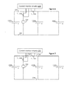
- Figure 1 shows a block diagram example of a portable electronic device.
- FIG. 2 shows a battery pack in accordance with embodiment of the present disclosure.
- FIG. 3 shows a battery pack and charge controller circuitry in accordance with other embodiments of the present disclosure.
- FIG. 4 shows a battery arrangement in accordance with embodiments of the present disclosure.
- FIG. 5 shows another battery arrangement in accordance with embodiments of the present disclosure.
- Figure 6 shows the battery arrangement of Figure 5 with a first example of connection faults.
- Figure 7 shows the battery arrangement of Figure 5 with a second example of connection faults.
- Figure 8 shows the battery arrangement of Figure 5 with a third example of connection faults.
- Figure 9 shows the battery arrangement of Figure 5 with a fourth example of connection faults.
- Figure 10 shows a general embodiment of a battery arrangement in accordance with the present disclosure, and also shows examples of connection faults.
- Figure 11A shows another general embodiment of a battery arrangement in accordance with the present disclosure, and also shows examples of connection faults.
- Figure 11B shows a four-battery example of the embodiment of Figure 11A .
- Figure 12 shows a pair of closed loops from the general embodiment of Figure 10 .
- Figure 13 shows a current branch take from the two closed loops of Figure 12 .
- Figure 14 shows another current branch take from the two closed loops of Figure 12 .
- Figures 15-17 show alternate arrangements of electrical components in the two closed loops of Figure 12 .
- Figure 18 shows a pair of closed loops from the general embodiment of Figure 11 .
- Figures 19-21 show alternate arrangements of electrical components in the two closed loops of Figure 18 .
- Figures 22-24 shows current branches taken from the two closed loops of Figure 20 .
- Figure 25 shows another general embodiment of a battery arrangement in accordance with the present disclosure.
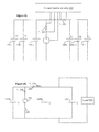
- Figure 26 shows an embodiment of a battery arrangement connected to a load, the battery arrangement includes switching devices used to electrically connect a controllable current charge device and sense resistors to the battery arrangement.
- Figure 27 shows a flowchart of a method according to certain examples of the present disclosure.
- Figure 28 shows a flowchart of a method according to certain other examples of the present disclosure.
- Figure 29 shows an embodiment of with multiple batteries electrically connected to load.
- Figure 30 shows the embodiment of Figure 30 with multiple possible connection faults.
- Figure 31 shows an embodiment of multiple fuel cells electrically connected to load.
- Figure 32 shows an embodiment of a load.
- Figure 33 shows another embodiment of a load electrically connected to a battery.
- the present disclosure provides a method and system to charge efficiently and safely batteries comprised in an electronic device.
- the method and system performs measurement of electrical currents flowing in different branches of an electrical circuit that comprises the batteries and determines if there if there is a battery connection fault.
- the charge current used to charge the batteries is adjusted in accordance with the detected fault, or absence thereof, such as to ensure that the charge current received by each battery does not exceed a safe current limit.
- the embodiments described herein generally relate to portably powered (typically, but not exclusively, battery-powered) electronic devices such as, for example, portable electronic devices.
- portable electronic devices can be mobile communication devices, cellular phones, cellular smart-phones, wireless communication devices, tablet computers (which can be referred to simply as tablets) and the like, personal digital assistants (PDAs), cameras, calculators, mobile gaming devices, personal audio/video devices, etc.
- PDAs personal digital assistants
- Such portable electronic devices may be handheld, that is, sized and shaped to be held and carried in a human hand, and used while held or carried.
- a portable electronic device can be a two-way communication device with data communication capabilities including the capability to communicate with other mobile devices or computer systems through a network of transceiver stations.
- the portable electronic device which may be referred to as a mobile device, may also have the capability to allow voice communication.
- a data messaging device a two-way pager, a cellular telephone with data messaging capabilities, a wireless Internet appliance, or a data communication device.
- FIG. 1 Shown in Figure 1 , is a block diagram of an exemplary embodiment of a portable electronic device 100.
- the portable electronic device 100 includes a number of components such as a main processor 102 that controls the overall operation of the portable electronic device 100. Communication functions, including data and voice communications, are performed through a radio frequency (RF) communication subsystem 104.
- RF radio frequency
- Data received by the portable electronic device 100 can be decompressed and decrypted by decoder 103, operating according to any suitable decompression techniques (e.g. YK decompression, and other known techniques) and encryption techniques (e.g. using an encryption techniques such as Data Encryption Standard (DES), Triple DES, or Advanced Encryption Standard (AES)).
- decompression techniques e.g. YK decompression, and other known techniques
- encryption techniques e.g. using an encryption techniques such as Data Encryption Standard (DES), Triple DES, or Advanced Encryption Standard (AES)
- the RF communication subsystem 104 receives messages from, and sends messages to, a wireless network 200.
- the RF communication subsystem 104 is configured in accordance with the Global System for Mobile Communication (GSM) and General Packet Radio Services (GPRS) standards.
- GSM Global System for Mobile Communication
- GPRS General Packet Radio Services
- the GSM/GPRS wireless network is used worldwide and it is expected that these standards will be superseded eventually by Enhanced Data GSM Environment (EDGE) and Universal Mobile Telecommunications Service (UMTS). New standards are still being defined, but it is believed that they will have similarities to the network behavior described herein, and it will also be understood by persons skilled in the art that the embodiments described herein are intended to use any other suitable standards that are developed in the future.
- the wireless link connecting the RF communication subsystem 104 with the wireless network 200 represents one or more different Radio Frequency (RF) channels, operating according to defined protocols specified for GSM/GPRS communications. With newer network protocols, these channels are capable of supporting both circuit switched voice communications and packet switched data communications.
- the RF communication subsystem 104 can comprise a baseband processor 105 that manages the functions of the communication system 104.
- wireless network 200 associated with portable electronic device 100 is a GSM/GPRS wireless network in one exemplary implementation
- other wireless networks may also be associated with the portable electronic device 100 in variant implementations.
- the different types of wireless networks that may be employed include, for example, data-centric wireless networks, voice-centric wireless networks, and dual-mode networks that can support both voice and data communications over the same physical base stations.
- Combined dual-mode networks include, but are not limited to, Code Division Multiple Access (CDMA) or CDMA2000 networks, GSM/GPRS networks (as mentioned above), and future third-generation (3G) networks like EDGE and UMTS.
- CDMA Code Division Multiple Access
- GSM/GPRS networks as mentioned above
- 3G third-generation
- Some other examples of data-centric networks include Wi-Fi 802.11, MobitexTM and DataTACTM network communication systems.
- Examples of other voice-centric data networks include Personal Communication Systems (PCS) networks like GSM and Time Division Multiple Access (TDMA) systems.
- PCS Personal Communication Systems
- TDMA
- the main processor 102 also interacts with additional subsystems such as a Random Access Memory (RAM) 106, a flash memory 108, a display 110, an auxiliary input/output (I/O) subsystem 112, a data port 114, a keyboard 116, a speaker 118, a microphone 120, short-range communications 122, a battery pack 129, and other device subsystems 124.
- RAM Random Access Memory
- flash memory 108 flash memory
- I/O auxiliary input/output subsystem
- the display 110 can include a touch-sensitive display.
- the display 110 and the keyboard 116 may be used for both communication-related functions, such as entering a text message for transmission over the network 200, and device-resident functions such as a calculator or task list.
- the portable electronic device 100 can send and receive communication signals over the wireless network 200 after required network registration or activation procedures have been completed.
- Network access is associated with a subscriber or user of the portable electronic device 100.
- the portable electronic device 100 To identify a subscriber, the portable electronic device 100 requires a SIM/RUIM card 126 (i.e. Subscriber Identity Module or a Removable User Identity Module) to be inserted into a SIM/RUIM interface 128 in order to communicate with a network.
- SIM/RUIM card 126 is one type of a conventional "smart card” that can be used to identify a subscriber of the portable electronic device 100 and to personalize the portable electronic device 100, among other things. Without the SIM/RUIM card 126, the portable electronic device 100 is not fully operational for communication with the wireless network 200.
- the SIM/RUIM card 126 By inserting the SIM/RUIM card 126 into the SIM/RUIM interface 128, a subscriber can access all subscribed services. Services may include: web browsing and messaging such as e-mail, voice mail, Short Message Service (SMS), and Multimedia Message Service (MMS). More advanced services may include: point of sale, field service and sales force automation.
- the SIM/RUIM card 126 includes a processor and memory for storing information. Once the SIM/RUIM card 126 is inserted into the SIM/RUIM interface 128, it is coupled to the main processor 102. In order to identify the subscriber, the SIM /RUIM card 126 can include some user parameters such as an International Mobile Subscriber Identity (IMSI).
- IMSI International Mobile Subscriber Identity
- the SIM/RUIM card 126 may store additional subscriber information for a portable electronic device as well, including datebook (or calendar) data and recent call data. Alternatively, user identification data and other data items can also be programmed into the flash memory 108.
- the portable electronic device 100 is a battery-powered device that includes the battery pack 129, which contains, among other components, two or more rechargeable electrical energy sources such as, for example, batteries 130.
- the batteries 130 can be smart batteries with an embedded microprocessor that can communicate with the main processor 102 and that can control operations related to the batteries.
- the battery assembly can provide a voltage V+ to the portable electronic device (e.g., V+ can be provided to the main processor 102, or to any other power-consuming component of the portable electronic device 100).
- V+ voltage
- future technologies such as micro fuel cells or capacitor-based power supplies may provide the power to the portable electronic device 100.
- batteries, micro fuel cells, capacitor-based based power supplies, or any other device that can produce an electrical output usable by the portable electronic device 100 can all be referred to as electrical energy sources, which may be rechargeable.
- the portable electronic device 100 also includes an operating system 134 and software components 136 to 146 which are described in more detail below.
- the operating system 134 and the software components 136 to 148 that are executed by the main processor 102 are typically stored in a persistent store such as the flash memory 108, which may alternatively be a read-only memory (ROM) or similar storage element (not shown).
- a persistent store such as the flash memory 108
- ROM read-only memory
- portions of the operating system 134 and the software components 136 to 146 such as specific device applications, or parts thereof, may be temporarily loaded into a volatile store such as the RAM 106.
- Other software components can also be included, as is well known to those skilled in the art.
- the subset of software applications 136 that control basic device operations, including data and voice communication applications, will normally be installed on the portable electronic device 100 during its manufacture.
- Other software applications include a message application 138 that can be any suitable software program that allows a user of the portable electronic device 100 to send and receive electronic messages.
- Messages that have been sent or received by the user are typically stored in the flash memory 108 of the portable electronic device 100 or some other suitable storage element in the portable electronic device 100. In at least some embodiments, some of the sent and received messages may be stored remotely from the device 100 such as in a data store of an associated host system that the portable electronic device 100 communicates with.
- the software applications can further include a device state module 140, a Personal Information Manager (PIM) 142, and other suitable modules (not shown).
- the device state module 140 provides persistence, i.e. the device state module 140 ensures that important device data is stored in persistent memory, such as the flash memory 108, so that the data is not lost when the portable electronic device 100 is turned off or loses power.
- the PIM 142 includes functionality for organizing and managing data items of interest to the user, such as, but not limited to, e-mail, contacts, calendar events, appointments, and task items.
- the PIM 142 can also organize and manage any voice mails recorded on the portable electronic device 100.
- a PIM application has the ability to send and receive data items via the wireless network 200.
- PIM 142 data items may be seamlessly integrated, synchronized, and updated via the wireless network 200 with the portable electronic device subscriber's corresponding data items stored in, or accessible by, a host computer system. This functionality creates a mirrored host computer on the portable electronic device 100 with respect to such items. This can be particularly advantageous when the host computer system is the portable electronic device subscriber's office computer system.
- the portable electronic device 100 also includes a connect module 144, and an information technology (IT) policy module 146.
- the connect module 144 implements the communication protocols that are required for the portable electronic device 100 to communicate with the wireless infrastructure and any host system, such as an enterprise system, that the portable electronic device 100 is authorized to interface with.
- the connect module 144 includes a set of application programming interfaces (APIs) that can be integrated with the portable electronic device 100 to allow the portable electronic device 100 to use any number of services associated with the enterprise system.
- APIs application programming interfaces
- the connect module 144 allows the portable electronic device 100 to establish an end-to-end secure, authenticated communication pipe with the host system.
- a subset of applications for which access is provided by the connect module 144 can be used to pass information technology (IT) policy commands from the host system to the portable electronic device 100. This can be done in a wireless or wired manner.
- IT policy module 146 can then be passed to the IT policy module 146 to modify the configuration of the device 100. Alternatively, in some cases, the IT policy update can also be done over a wired connection.
- the subset of software applications 136 can also include high power applications 148.
- high power applications include, for example, three-dimensional gaming, web browsing, video conference calling, and video recording.
- software applications can also be installed on the portable electronic device 100.
- These software applications can be third party applications, which are added after the manufacture of the portable electronic device 100. Examples of third party applications include games, calculators, utilities, etc.
- the additional applications can be loaded onto the portable electronic device 100 through at least one of the wireless network 200, the auxiliary input/output (I/O) subsystem 112, the data port 114, the short-range communications subsystem 122, or any other suitable device subsystem 124.
- This flexibility in application installation increases the functionality of the portable electronic device 100 and may provide enhanced on-device functions, communication-related functions, or both.
- secure communication applications may enable electronic commerce functions and other such financial transactions to be performed using the portable electronic device 100.
- the data port 114 enables a subscriber to set preferences through an external device or software application and extends the capabilities of the portable electronic device 100 by providing for information or software downloads to the portable electronic device 100 other than through a wireless communication network.
- the alternate download path may, for example, be used to load an encryption key onto the portable electronic device 100 through a direct and thus reliable and trusted connection to provide secure device communication.
- the data port 114 can be any suitable port that enables data communication between the portable electronic device 100 and another computing device.
- the data port 114 can be a serial or a parallel port.
- the data port 114 can be a USB port that includes data lines for data transfer and a supply line that can provide a charging current to charge the battery 130 of the portable electronic device 100.
- the short-range communications subsystem 122 provides for communication between the portable electronic device 100 and different systems or devices, without the use of the wireless network 200.
- the subsystem 122 may include an infrared device and associated circuits and components for short-range communication.
- Examples of short-range communication standards include standards developed by the Infrared Data Association (IrDA), Bluetooth, and the 802.11 family of standards developed by IEEE.
- a received signal such as a text message, an e-mail message, or web page download will be processed by the RF communication subsystem 104 and input to the main processor 102.
- the main processor 102 will then process the received signal for output to the display 110 or alternatively to the auxiliary I/O subsystem 112.
- a subscriber may also compose data items, such as e-mail messages, for example, using the keyboard 116 in conjunction with the display 110 and possibly the auxiliary I/O subsystem 112.
- the auxiliary subsystem 112 may include devices such as: a touch screen, mouse, track ball, infrared fingerprint detector, or a roller wheel with dynamic button pressing capability.
- the keyboard 116 may be an alphanumeric keyboard, a telephone-type keypad, or both.
- keyboard functionality can be provided to the user through a touch-sensitive display that may be included in the display 110.
- Other types of keyboards may also be used.
- a composed item may be transmitted over the wireless network 200 through the RF communication subsystem 104.
- the overall operation of the portable electronic device 100 is substantially similar, except that the received signals are output to the speaker 118, and signals for transmission are generated by the microphone 120.
- Alternative voice or audio I/O subsystems such as a voice message recording subsystem, can also be implemented on the portable electronic device 100.
- voice or audio signal output is accomplished primarily through the speaker 118, the display 110 can also be used to provide additional information such as the identity of a calling party, duration of a voice call, or other voice call related information.
- the scope of the present disclosure encompasses the detection of electrical connection faults in arrangements of electrical energy sources electrically connected to each other.
- the detection of such faults allows in, in some embodiments, to adjust a charge current being supplied to the electrical energy sources to charge the electrical energy sources. In other embodiments, detection of such faults allows to adjust a supply current being supplied, by the electrical energy sources, to an electrical load.
- FIG. 2 shows an example of a battery pack 129 of the present disclosure.
- the battery pack 129 comprises batteries 130, sense resistors 220, current monitor circuitry 222, and controllable charge current source 224, which can also be referred to as an electrical current source.
- the sense resistors 220 and the current monitor circuitry 222 are used to measure (monitor) electrical current flowing in various branches in the electrical circuitry of the battery pack 129. By measuring these current, it is possible to detect connection fault of the batteries in the battery pack 129 (i.e., it is possible to detect if a battery has been disconnected).
- the controllable charge current source 224 controls the level of a charge current provided to charge (recharge) the batteries 130 in accordance with the measured currents.
- the controllable charge current source 224 takes an electrical charge signal provided by a charge source, which is exterior to the portable electronic device 100, and adjusts, according to current values sensed at the sense resistors 220, the charge current provided to the batteries 130.
- the charge current provided to the batteries can be set in accordance with safety measures to avoid any of the batteries being subjected to a charge current greater than its maximum allowable charge current.
- FIG. 3 shows another example of a battery pack 129 that has the controllable charge current source 224 located outside the battery pack 129. That is, the controllable charge current source 224 is located elsewhere in the portable electronic device 100.
- the current monitoring circuitry can include the processor 102 shown at Figure 1 , which can receive sensed (monitored) current values from current sensing circuitry through any suitable communication protocol such as, for example, the I 2 C protocol, 1wire bus, system management bus (SMBUS), or the like. In accordance with (as a function of) the sensed current values, the processor 102 can control the controllable charge current source 224 shown at Figures 2 and 3 .
- Figure 4 shows an example of an arrangement of three batteries 130A, 130B, and 130C in the battery pack 129 of Figure 3 .
- the batteries 130A, 130B, and 130C have nominal voltages Va, Vb, and Vc, and internal resistance values r a_int , r b_int , and r c_int respectively.
- the batteries 130A, 130B, and 130C are electrically connected to the controllable charge current source 224 and to sense resistors r s1 228 and r s2 230.
- the controllable charge current source 224 provides a charge current in accordance with a control signal provided by the current monitor circuitry 222.
- control signal can be a function of current values sensed by the current monitor circuitry 222 at sense resistors r s1 228 and r s2 230, or can be a function of the ratio of current flowing through sense resistors r s1 228 and r s2 230.
- the sense resistors r s1 228 and r s2 230 can have any suitable resistance values.
- the resistance value of each sense resistor can be any value ranging from 10 to 100 m ⁇ , or any other value that produces a measurable voltage drop.
- the voltage drop across the sense resistor can be considerably less that the voltage of a battery and, does not cause excessive resistive losses.
- the batteries 130B and 130C are electrically connected to each other in parallel.
- the positive electrodes of the batteries 130B and 130C are electrically connected to one end of the sense resistors r s2 230.
- the negative electrodes of the batteries 130B and 130C are electrically connected to the negative electrode of the battery 130A and to the negative electrode of controllable charge current source 224.
- the positive electrode of the battery 130A is electrically connected to the sense resistors r s1 228 and to the sense resistor r s2 230.
- the sense resistor r s1 228 is connected to the positive electrode of controllable charge current source 224.
- the batteries 130A, 130B, and 130C can have any suitable nominal voltage and be based upon any suitable battery chemistry.
- Each battery can have a voltage different than that of the other batteries.
- FIG. 4 Also shown in Figure 4 are three closed loops, namely the closed loop defined by the nodes a-b-f-e, the closed loop defined by the nodes b-c-g-f , and the closed loop defined by the nodes c-d-h-g.
- a closed loop can also be referred to as Kirchhoff loop.
- the embodiment of Figure 4 shows that the controllable charge current source 224, the sense resistor 228, the sensor resistor 230, the battery 130A, and the battery 130B are electrically connected to each other and define a first closed loop ( a-b-f- e) and a second closed loop ( b-c-g-f ).
- the first closed loop ( a-b-f-e ) comprises the controllable charge current source 224, the sense resistor 228, and the battery 130A.
- the second closed loop ( b-c-g-f ) comprises the controllable charge current source 224, the sense resistor 228, the sense resistor 230, and the battery 130B.
- the sense resistor 228 and the sense resistor 230 or on different (distinct) current branches.
- Figure 5 shows an embodiment of the example of Figure 4 with the nominal voltages Va, Vb, and Vc having the same value V; with the internal resistance values r a_int , r b_int , and r c_int having same value r int ; and with the sense resistors r s1 228 and r s2 230 having the same value r s .
- the internal resistance can be referred to as an equivalent series resistance.
- the resistance of the sense resistors 228 and 230 is the same in the present example, this need not be the case. In examples where the resistance value of the sense resistors 228 and 230 is different, a different relation between I(r s 230) and I(r s 228) will exist and be equally indicative that no faults are present.
- Figures 6-9 show how faults can be detected in the battery arrangement of Figure 5 .
- the internal resistances of the batteries are assumed equal among themselves and are not shown and, the nodes a through h are not shown in Figures 6-9 .
- Figure 6 shows the electrical circuit of Figure 5 but with two faults 232 between the battery 130A and the remainder of the electrical components in the electrical circuit.
- Each fault 232 is a break in the electrical connection between the battery 130A and the remainder of the electrical circuit.
- Such a break in connection could occur, for example, when the battery 130A is electrically connected to the controllable charge current circuitry 224 through a flex connector that becomes broken or damaged.
- I(r s 230) I(r s 228).
- FIG. 7 shows three faults 234 between the batteries 130B and 130C, and the remainder of the electrical components of the electrical circuit.
- Each fault 234 is a break in the electrical connection between the batteries 130A and 130B and the remainder of the electrical circuit.
- FIG. 8 shows two faults 236 between the battery 130B and the remainder of the electrical components of the electrical circuit.
- Each fault 236 is a break in the electrical connection between the batteries 130B and the remainder of the electrical circuit.
- FIG. 9 shows two faults 238 between the battery 130C and the remainder of the electrical components of the electrical circuit of Figure 9 .
- Each fault 238 is a break in the electrical connection between the batteries 130C and the remainder of the electrical circuit.
- Table 1 summarizes the above relationships between the currents I(r s 230), I(r s 228), and the various faults 232-238.
- the faults can be caused by a break in a flex circuit or any other type of electrical conductor connecting the electrical components of the electrical circuits shown at Figures 4-9 .
- the current monitor circuitry 222 can monitor I(r s 230) and I(r s 228) and adjust the charge current provided by the charge controller circuitry 224 as follows.
- the maximum charge current should be set to I max in order not to exceed the safe charge current limit.
- the maximum charge current should be set to
- Additional sense resistors may be added to other distinct branches of the electrical circuit. Monitoring, by the current monitor circuitry 222, of the electrical current flowing through these additional resistors would allow determining if in fact more than one fault is present.
- Such additional resistors and branches are optional, however; it may be satisfactory in some cases to determine that a fault has occurred-and notifying a user of a fault prompting a repair to be made-and it may be less important to determine how many faults have occurred or what the particular faults may be.
- Table 2 summarizes the above relationships between I(r s 230), I(r s 228), and the charge current.
- Monitoring the individual current flowing through the sense resistors 228 and 230 can include monitoring the ratio of the currents flowing through sense resistors 228 and 230.
- the current monitoring circuitry 222 may be equipped with current dividing circuitry that take the current values measured at the sense resistors 228 and 230 as inputs, and outputs the ratio of the current values.
- Figure 10 show an embodiment of an arrangement of N batteries 130-1 to 130-N.
- I r S 230 N - M N - a ⁇ I r S 228 for a ⁇ 1 ⁇ K where a corresponds to fault 300-a.
- I r S 230 b - L b - 1 ⁇ I r S 228 for b ⁇ L ⁇ N where b corresponds to fault 300-b.
- Figure 11B shows an example of the embodiment of Figure 11A with four batteries 130A, 130B, 130C, and 130D in the battery pack 129 of Figure 2 .
- the batteries 130A, 130B, 130C, and 130D have the same nominal voltage V, and the same internal resistance value r int .
- the batteries 130A, 130B, 130C, and 130D are electrically connected to the charge controller circuitry 224 and to sense resistors r s 228 and r s 230, which have substantially the same resistance value.
- the charge controller circuitry 224 provides a charge current in accordance with a control signal provided by the current monitor circuitry 222, the control signal is a function of current values sensed at sense resistors r s 228 and r s 230.
- the batteries 130B, 130C, and 130D are electrically connected in parallel.
- the battery 130A is connected to the batteries 130B, 130C, and 130D through the sense resistor r s 230.
- the charge controller circuitry 224 is electrically connected to the batteries 130A, 130B, 130C, and 130D and to the sense resistor r s 230, through the sense resistor r s 228.
- Figure 11B also shows faults 240, 242, 244, 246, 248, and 250.
- the relationship between current flowing through r s 230, I(r s 230), and the current flowing through r s 230, I(r s 228), is as follows.
- Table 3 summarizes these relationships.
- the current monitor circuitry 222 can control the controllable charge current circuitry 224 as a function of a ratio of the currents flowing through the sense resistors 228 and 230.
- Table 4 summarizes the above relationships between I(r s 230), I(r s 228), and the charge current.
- Figures 12-17 show different possible configurations of the sense resistors 228 and 230 within a battery arrangement such as the battery arrangement of Figure 10 .
- the sense resistors 228 and 230 have one of their ends directly electrically connected to each other at the three-branch node 252 and thus have the three-branch node 252 between them. Also in Figure 12 , the sense resistor 228 has one of its ends connected to the controllable charge circuitry 224, which is electrically connected to the three-branch node 254. The battery 130-2 is electrically connected to the three-branch node 254 and to the sense resistor 230. As such, the sense resistors 228 and 230 also have a second three-branch node, the three-branch node 254, between them.
- the sense resistor 228 is on the current branch that spans nodes 252 and 254, and that includes the controllable charge current circuitry 224.
- the current branch in question is shown as current branch 256 in Figure 13 .
- the sense resistor 230 is on the current branch that spans the nodes 252 and 254, and that includes the battery 130-2. This current branch is shown as current branch 258 in Figure 14 .
- the current branch 256 is distinct from the current branch 258.
- Figures 15-17 also show the sense resistors 228 and 238 separated from each other by the two, three-branch nodes 252 and 254. Further, Figures 15-17 show that the sense resistors are disposed (located) on different current branches, namely on the current branch 256 and current branch 258. Any other configurations having the sense resistors 228 and 230 on different current branches are also within the scope of the present disclosure.
- Figures 18-21 show different possible configurations of the sense resistors 228 and 230 within a battery arrangement similar to that of Figure 11 , but with only two batteries 130-1 and 130-2. As in the embodiments of Figures 12, and 15-17 , the sense resistors 228 and 220 in the embodiments of Figures 18-21 are separated from each other by two, three-branch nodes 252 and 254.
- each sense resistor in the embodiments of Figures 18-21 is on a distinct current branch: in the embodiments of Figures 18, 19, and 21 , the sense resistor 228 is on the current branch 260 and the sense resistor 230 is on the current branch 262; in the embodiment of Figure 20 , the sense resistor 228 is on the current branch 260 and the sense resistor 230 is on the current branch 264.
- the current branches 260, 262, and 264 of the embodiment of Figure 20 are shown by themselves in Figures 22, 23, and 24 respectively. Any other configurations having the sense resistors 228 and 230 on different current branches are also within the scope of the present disclosure.
- FIG 25 shows another embodiment of an arrangement of N batteries 130-1 to 130-N each having a respective voltage V 1 -V N .
- Each battery may have a voltage different than the other battery voltages.
- each internal resistance of the batteries may be different than the other internal resistances.
- the resistance of each sense resistor 228 and 230 does not have to be the same. In the present general embodiment, it can be shown, through principles of conservation of charge and energy in electrical circuits, e.g., through Kirchhoff's circuit laws, that it is possible to detect the occurrence of faults by measuring the electrical current flowing through the sense resistors 228 and 230.
- any other suitable type of rechargeable electrical energy source may be used instead of, or in concert with, batteries.
- capacitor-based electrical energy sources may be used instead of, or in concert with, batteries.
- Figure 26 shows the three battery arrangement of Figure 5 , but with the batteries not being recharged.
- the battery arrangement is electrically connected to a load 302 of the portable electronic device 100 of Figure 1 .
- a switching device 304 is open to disconnect the controllable charge current circuitry 224 and the sense resistor 228 from the batteries 130A, 130B, and 130C;
- a switching device 306 is set to disconnect the sense resistor 230 from the batteries 130A, 130B, and 130C, and to connect all three batteries in parallel.
- the switching devices 304 and 306 can be operationally connected to, and controlled by, the processor 102 of the portable electronic device 100, shown at Figure 1 .
- the switching device 304 can be opened, and the switching device 306 toggled to by-pass the sense resistor 230.
- the switching devices can include any suitable switch such as solid state switches and the like.
- Figure 27 shows a flowchart of a method according to certain examples of the present disclosure.
- a charge current is provided to an electrical energy source arrangement such as, for example, the battery pack 129 of the portable electronic device 100 shown at Figure 1 .
- the electrical energy sources can be rechargeable batteries.
- Action 400 of Figure 27 can include, or be preceded by, connecting the portable electronic device that contains the electrical energy source arrangement to a charger (charging device) and detecting, at the electronic device, that the charger has been connected.
- Action 400 can also include, or be preceded by, configuring the electrical energy source arrangement to allow charging of the electrical energy sources (e.g., batteries) by, for example, setting switching devices, such as, for example, the switching devices 304 and 306 shown at Figure 26 , to establish proper electrical connections to allow charging in accordance with the present disclosure.
- the electrical energy sources e.g., batteries
- setting switching devices such as, for example, the switching devices 304 and 306 shown at Figure 26
- the ratio of currents in a pair of current sensing devices comprised in the electrical energy source arrangement is measured to obtain a measured ratio.
- the current sensing devices can be sense resistors (e.g., sense resistor 228 and 230 shown at Figures 10 and 11 .
- the ratio can be measured at the output of a divider circuit comprised in current monitor circuitry.
- a pre-determined value includes any value or range of values decided upon, explicitly or implicitly, at any time before the comparison 404.
- one or more pre-determined ratio values may be values that have been stored in memory, such as flash memory 108. Each pre-determined ratio value can be indicative of the presence of a particular fault in the electrical energy source arrangement, and thus indicate the maximum allowable charge current to be provided to the electrical energy source arrangement to charge the electrical energy sources safely.
- a match is identified between the measured ratio and the pre-determined ratio values.
- the match indicates the maximum charge current that should be provided to the electrical energy source arrangement. If the current provided at action 400 is different than that maximum charge current indicated by the match of action 406, then, in accordance to the match, the charge current provided to the electrical energy source arrangement is set (adjusted), at action 408, to the maximum charge current value for this particular match.
- the method of the present disclosure can also include an action 410 that determines, in accordance with the match determined at action 406, if there is a fault in the electrical energy source arrangement. If there is a fault, an indication (such as a notification that is visual, audible, tactile, or a combination thereof) can be provided or supplied to the user of the electrical energy source arrangement at action 412.
- the indication can be provided in any suitable manner or form such as, for example, in the form of a message or pictogram displayed on the display 110, or in the form of an audible signal output at the speaker 118, or in the form of an haptic signal when the portable electronic device 100 is equipped with vibrating elements, or in any other suitable manner.
- the user can take action in terms of replacing or repairing the electronic device containing the electrical energy source arrangement.
- FIG 28 shows a flowchart of a method according to some examples of the present disclosure.
- a charge current is provided to an electrical energy source arrangement such as, for example, the battery pack 129 of the portable electronic device 100 shown at Figure 1 .
- the initial charge current can be set to the maximum charge current for a single electrical energy source. This mitigates the risk of providing an unsafe charge current in scenarios where faults (electrical connection faults) are present in the battery pack and only a single energy source is connected to the charger (the controllable charge current source 224).
- the electrical energy sources can be rechargeable batteries.
- Action 414 of Figure 28 can include, or be preceded by, connecting the portable electronic device that contains the electrical energy source arrangement to a charger (charging device) and detecting, at the electronic device, that the charger has been connected.
- Action 414 can also include, or be preceded by, configuring the electrical energy source arrangement to allow charging of the electrical energy sources (e.g., batteries) by, for example, setting switching devices, such as, for example, the switching devices 304 and 306 shown at Figure 26 , to establish proper electrical connections to allow charging in accordance with the present disclosure.
- the electrical energy sources e.g., batteries
- a current is measured in a first current sensing device to obtain a first measured current.
- a current is measured in a second current sensing device to obtain a second measured current.
- the first and current sensing devices can be current sense resistors, Hall effect sensors, or any other suitable current sensing element across which a voltage drop is proportional to the electrical current traversing the current sensing element.
- the first measured current and the second measured current are compared to pre-determined current values.
- a match between the first measured current and the pre-determined current values is identified.
- a match between the second measured current and the pre-determined current values is identified.
- the charge current provided to the electrical energy source arrangement is set (adjusted), at action 426, to the maximum charge current value for this particular pair of matches.
- the matches obtained at actions 422 and 424 are used to determine if there is a fault (connection fault) in the electrical energy source arrangement. If there is a fault, an indication can be provided to the user of the electrical energy source arrangement at action 414.
- the indication can be provided in any suitable manner or form such as, for example, in the form of a message or pictogram displayed on the display 110, or in the form of an audible signal output at the speaker 118, or in the form of an haptic signal when the portable electronic device 100 is equipped with vibrating elements, or in any other suitable manner.
- the user can take action in terms of replacing or repairing the electronic device containing the electrical energy source arrangement.
- Figure 29 shows an embodiment of three batteries 130A, 130B, and 130C having the same nominal voltage value V.
- Each battery has the same internal resistance value (electrical series resistance).
- Sense resistors r s1 228 and r s2 230 are electrically connected to the batteries 130A, 130B, and 130C, which are electrically connected to a load 500 to provide a supply current to the load 500.
- the load can be the elements of the portable electronic device 100 of Figure 1 , excluding the battery back 129.
- FIG. 29 Also shown in Figure 29 are three closed loops, namely the closed loop defined by the nodes a-b-f-e , the closed loop defined by the nodes b-c-g-f , and the closed loop defined by the nodes c-d-h-g.
- a closed loop can also be referred to as Kirchhoff loop.
- the embodiment of Figure 29 shows that the load 500, the sense resistor 228, the sensor resistor 230, the battery 130A, and the battery 130B are electrically connected to each other and define a first closed loop ( a-b-f-e ) and a second closed loop ( b-c-g-f ) .
- the first closed loop ( a-b-f-e ) comprises the load 500, the sense resistor 228, and the battery 130A.
- the second closed loop ( b-c-g-f ) comprises the load 500, the sense resistor 228, the sense resistor 230, and the battery 130B.
- Figure 30 shows the battery arrangement of Figure 29 but with electrical connection faults 232, 234, 236, and 238. Using Kirchhoff's laws, it can be shown that when one or more of these faults are present, the relationship between the currents flowing through the sense resistors 228 and 230 are as reported in Table 5.
- the current monitoring circuitry 222 can monitor I(r s 230) and I(r s 228) continuously, periodically, or in any other suitable way. In accordance with (as a function of) the monitored currents I(r s 230) and I(r s 228), the current monitoring circuitry 222 can provide commands to the load 500. For example, when any fault is detected, the current monitoring circuitry can control the load 500 to reduce its power consumption in order to delay the next battery charging operation. In turn, the load 500 can turn off, or use less frequently, some of its components.
- the processor 102 upon receiving notification from the current monitoring circuitry, can to turn off the radio frequency communication subsystem 104, or reduce the display intensity of the display 110. Additionally, the processor can display a warning on the display 110 to advise the user that a fault in the battery pack has occurred and that servicing might be required.
- controllable charge current source 224 shown in the embodiments of Figures 10-26 can be replaced by the load 500 shown in the embodiments of Figures 29-33 to arrive at other embodiments that regard the detection of electrical connection faults in electrical circuits comprising electrical energy sources, during a discharging operation of the electrical energy sources, i.e., when the electrical energy sources provide power to a load.
- the batteries 130A, 130B, and 130C can be substituted with any other suitable electrical energy sources such as, for example, fuel cells, solar cells, and the like.
- the load can include a battery being charged by the fuel cells, and a power converter disposed between the fuel cells and the battery.
- the power converter converts an input current level provided by the fuel cells into an output current level that is provided to the battery to charge the battery.
- the power converter can be set, by the current monitoring circuitry 222, to convert the current level provided by the fuel cells to the current level required to charge the battery.
- Figure 31 shows the arrangement of Figure 29 but with the batteries 130A, 130B, and 130C having been replaced with fuel cells 630A, 630B, and 630C.
- Figure 32 shows the load 500, which, in the present embodiment comprises a power converter 600 and a battery 602 that is to be charged by a charge current provided by the power converter 600.
- Figure 33 shows a variant of the load shown at Figure 32 . In figure 33 , the load 500 is simply the power converter 600, which is electrically connected to the battery 600 to provide a charge current thereto.
- the fuel cells 630A, 630B, and 630C When no connection faults are present in the fuel cell arrangement of Figure 31 , the fuel cells 630A, 630B, and 630C will together provide an input current (I 1 ) to the load 500.
- the power converter 600 which, when nominally set to convert the input current I 1 , will convert I 1 into the pre-determined (target) charge current (I target ) of the battery 602. That is, the power converter 600 converts I 1 into I target .
- the current monitor circuitry 222 will notify the load 500 of this fault and the power converter 600 will change its conversion settings such that the power converter 600 converts 2*I 1 /3 into I target .
- two components are "electrically connected" when an electrical change caused by or affecting one (such as a change in voltage or current) can result in an electrical change in the other, or when an electrical signal sent by one can be received by the other.
- the two components need not be directly electrically connected (that is, there may be other elements interposed between them), and they may be, but need not be, proximate to one another.
- Electrically connected also includes the concept that components may be physically connected but the electrical circuit connections between them may be broken or completed by, for example, switching circuitry.
- the electronic device that is powered by a battery pack effectively seals the battery pack within its housing. That is, in those embodiments, the battery pack is not accessible to the user of the electronic device without particular tools and equipment. In such embodiments, as removal of the battery pack cannot generally be effected by the user, a simple substitution of the battery pack with a fresh battery pack is not possible in situations where the user observes inadequate battery lifetime or excessive charge time.
- the present disclosure allows the user to be notified when faults (electrical connection faults) are detected during charging of the electronic device. Upon receiving such notifications, the user can make appropriate plans such as servicing the electronic device.
- faults electrical connection faults
- the techniques described herein can be implemented with low cost in terms of added size or weight. Further, the potential for improved safety that may be afforded may be in addition to, and may act in cooperation with, other safety features.
- Embodiments of the disclosure can be represented as a software product stored in a machine-readable medium (also referred to as a computer-readable medium, a processor-readable medium, or a computer usable medium having a computer-readable program code embodied therein).
- the machine-readable medium can be any suitable tangible medium, including magnetic, optical, or electrical storage medium including a diskette, compact disk read only memory (CD-ROM), memory device (volatile or non-volatile), or similar storage mechanism.
- the machine-readable medium can contain various sets of instructions, code sequences, configuration information, or other data, which, when executed, cause a processor to perform steps in a method according to an embodiment of the disclosure.
- Those of ordinary skill in the art will appreciate that other instructions and operations necessary to implement the described disclosure can also be stored on the machine-readable medium.
- Software running from the machine-readable medium can interface with circuitry to perform the described tasks.
Landscapes
- Engineering & Computer Science (AREA)
- Power Engineering (AREA)
- Charge And Discharge Circuits For Batteries Or The Like (AREA)
- Secondary Cells (AREA)
Abstract
Description
- The present disclosure relates generally to electronic devices. More particularly, the present disclosure relates to electronic devices powered by multiple rechargeable energy sources.
- Present day electronic devices, particularly portable electronic devices such as, for example, smart phones and tablets can be equipped with a battery unit that comprises multiple rechargeable batteries or cells. The rechargeable batteries are electrically connected to each other to provide (or supply) an output voltage used to run the electronic device. Recharging of the battery unit requires providing a charge current to the battery unit. The maximum allowable value of the charge current is determined in accordance with the arrangement of the rechargeable cells, i.e., how they are electrically connected to each other, and in accordance with safety measures such as, for example, those set out by the International Association for the Wireless Communication Industry (CTIA), to ensure safety during the recharging process.
- For example, under such safety measures, an electronic device powered by a battery unit having multiple rechargeable same cells electrically connected to each other, for example, in parallel could have, as its maximum allowable charge current, the maximum allowable charge current for a single cell. This would ensures that in the case where the multiple rechargeable cells become electrically disconnected and only one rechargeable cell remains connected to the recharging unit, that the charge current would still be safe for that single remaining cell. However, having this "safe" charge current leads to long recharging times particularly when all the rechargeable cells are in place and electrically connected to each other.
- Improvements in portable devices that have a battery unit with multiple, electrically connected rechargeable cells are therefore desirable.
- Embodiments of the present disclosure will now be described, by way of example only, with reference to the attached Figures, wherein:
-
Figure 1 shows a block diagram example of a portable electronic device. -
Figure 2 shows a battery pack in accordance with embodiment of the present disclosure. -
Figure 3 shows a battery pack and charge controller circuitry in accordance with other embodiments of the present disclosure. -
Figure 4 shows a battery arrangement in accordance with embodiments of the present disclosure. -
Figure 5 shows another battery arrangement in accordance with embodiments of the present disclosure. -
Figure 6 shows the battery arrangement ofFigure 5 with a first example of connection faults. -
Figure 7 shows the battery arrangement ofFigure 5 with a second example of connection faults. -
Figure 8 shows the battery arrangement ofFigure 5 with a third example of connection faults. -
Figure 9 shows the battery arrangement ofFigure 5 with a fourth example of connection faults. -
Figure 10 shows a general embodiment of a battery arrangement in accordance with the present disclosure, and also shows examples of connection faults. -
Figure 11A shows another general embodiment of a battery arrangement in accordance with the present disclosure, and also shows examples of connection faults. -
Figure 11B shows a four-battery example of the embodiment ofFigure 11A . -
Figure 12 shows a pair of closed loops from the general embodiment ofFigure 10 . -
Figure 13 shows a current branch take from the two closed loops ofFigure 12 . -
Figure 14 shows another current branch take from the two closed loops ofFigure 12 . -
Figures 15-17 show alternate arrangements of electrical components in the two closed loops ofFigure 12 . -
Figure 18 shows a pair of closed loops from the general embodiment ofFigure 11 . -
Figures 19-21 show alternate arrangements of electrical components in the two closed loops ofFigure 18 . -
Figures 22-24 shows current branches taken from the two closed loops ofFigure 20 . -
Figure 25 shows another general embodiment of a battery arrangement in accordance with the present disclosure. -
Figure 26 shows an embodiment of a battery arrangement connected to a load, the battery arrangement includes switching devices used to electrically connect a controllable current charge device and sense resistors to the battery arrangement. -
Figure 27 shows a flowchart of a method according to certain examples of the present disclosure. -
Figure 28 shows a flowchart of a method according to certain other examples of the present disclosure. -
Figure 29 shows an embodiment of with multiple batteries electrically connected to load. -
Figure 30 shows the embodiment ofFigure 30 with multiple possible connection faults. -
Figure 31 shows an embodiment of multiple fuel cells electrically connected to load. -
Figure 32 shows an embodiment of a load. -
Figure 33 shows another embodiment of a load electrically connected to a battery. - Generally, the present disclosure provides a method and system to charge efficiently and safely batteries comprised in an electronic device. The method and system performs measurement of electrical currents flowing in different branches of an electrical circuit that comprises the batteries and determines if there if there is a battery connection fault. The charge current used to charge the batteries is adjusted in accordance with the detected fault, or absence thereof, such as to ensure that the charge current received by each battery does not exceed a safe current limit.
- It will be appreciated that for simplicity and clarity of illustration, where considered appropriate, reference numerals may be repeated among the figures to indicate corresponding or analogous elements. In addition, numerous specific details are set forth in order to provide a thorough understanding of the embodiments described herein. However, it will be understood by those of ordinary skill in the art that the embodiments described herein may be practiced without these specific details. In other instances, well-known methods, procedures and components have not been described in detail so as not to obscure the embodiments described herein. Also, the description is not to be considered as limiting the scope of the embodiments described herein.
- The embodiments described herein generally relate to portably powered (typically, but not exclusively, battery-powered) electronic devices such as, for example, portable electronic devices. The portable electronic devices can be mobile communication devices, cellular phones, cellular smart-phones, wireless communication devices, tablet computers (which can be referred to simply as tablets) and the like, personal digital assistants (PDAs), cameras, calculators, mobile gaming devices, personal audio/video devices, etc. Such portable electronic devices may be handheld, that is, sized and shaped to be held and carried in a human hand, and used while held or carried.
- A portable electronic device can be a two-way communication device with data communication capabilities including the capability to communicate with other mobile devices or computer systems through a network of transceiver stations. The portable electronic device, which may be referred to as a mobile device, may also have the capability to allow voice communication. Depending on the functionality provided by the mobile device, it may be referred to as a data messaging device, a two-way pager, a cellular telephone with data messaging capabilities, a wireless Internet appliance, or a data communication device. To aid the reader in understanding the structure of the mobile device, reference will now be made to
Figure 1 . - Shown in
Figure 1 , is a block diagram of an exemplary embodiment of a portableelectronic device 100. The portableelectronic device 100 includes a number of components such as amain processor 102 that controls the overall operation of the portableelectronic device 100. Communication functions, including data and voice communications, are performed through a radio frequency (RF)communication subsystem 104. Data received by the portableelectronic device 100 can be decompressed and decrypted bydecoder 103, operating according to any suitable decompression techniques (e.g. YK decompression, and other known techniques) and encryption techniques (e.g. using an encryption techniques such as Data Encryption Standard (DES), Triple DES, or Advanced Encryption Standard (AES)). TheRF communication subsystem 104 receives messages from, and sends messages to, awireless network 200. In this exemplary embodiment of the portableelectronic device 100, theRF communication subsystem 104 is configured in accordance with the Global System for Mobile Communication (GSM) and General Packet Radio Services (GPRS) standards. The GSM/GPRS wireless network is used worldwide and it is expected that these standards will be superseded eventually by Enhanced Data GSM Environment (EDGE) and Universal Mobile Telecommunications Service (UMTS). New standards are still being defined, but it is believed that they will have similarities to the network behavior described herein, and it will also be understood by persons skilled in the art that the embodiments described herein are intended to use any other suitable standards that are developed in the future. The wireless link connecting theRF communication subsystem 104 with thewireless network 200 represents one or more different Radio Frequency (RF) channels, operating according to defined protocols specified for GSM/GPRS communications. With newer network protocols, these channels are capable of supporting both circuit switched voice communications and packet switched data communications. TheRF communication subsystem 104 can comprise abaseband processor 105 that manages the functions of thecommunication system 104. - Although the
wireless network 200 associated with portableelectronic device 100 is a GSM/GPRS wireless network in one exemplary implementation, other wireless networks may also be associated with the portableelectronic device 100 in variant implementations. The different types of wireless networks that may be employed include, for example, data-centric wireless networks, voice-centric wireless networks, and dual-mode networks that can support both voice and data communications over the same physical base stations. Combined dual-mode networks include, but are not limited to, Code Division Multiple Access (CDMA) or CDMA2000 networks, GSM/GPRS networks (as mentioned above), and future third-generation (3G) networks like EDGE and UMTS. Some other examples of data-centric networks include Wi-Fi 802.11, Mobitex™ and DataTAC™ network communication systems. Examples of other voice-centric data networks include Personal Communication Systems (PCS) networks like GSM and Time Division Multiple Access (TDMA) systems. - The
main processor 102 also interacts with additional subsystems such as a Random Access Memory (RAM) 106, aflash memory 108, adisplay 110, an auxiliary input/output (I/O)subsystem 112, adata port 114, akeyboard 116, a speaker 118, amicrophone 120, short-range communications 122, abattery pack 129, andother device subsystems 124. Thedisplay 110 can include a touch-sensitive display. - Some of the subsystems of the portable
electronic device 100 perform communication-related functions, whereas other subsystems may provide "resident" or on-device functions. By way of example, thedisplay 110 and thekeyboard 116 may be used for both communication-related functions, such as entering a text message for transmission over thenetwork 200, and device-resident functions such as a calculator or task list. - The portable
electronic device 100 can send and receive communication signals over thewireless network 200 after required network registration or activation procedures have been completed. Network access is associated with a subscriber or user of the portableelectronic device 100. To identify a subscriber, the portableelectronic device 100 requires a SIM/RUIM card 126 (i.e. Subscriber Identity Module or a Removable User Identity Module) to be inserted into a SIM/RUIM interface 128 in order to communicate with a network. The SIM/RUIM card 126 is one type of a conventional "smart card" that can be used to identify a subscriber of the portableelectronic device 100 and to personalize the portableelectronic device 100, among other things. Without the SIM/RUIM card 126, the portableelectronic device 100 is not fully operational for communication with thewireless network 200. By inserting the SIM/RUIM card 126 into the SIM/RUIM interface 128, a subscriber can access all subscribed services. Services may include: web browsing and messaging such as e-mail, voice mail, Short Message Service (SMS), and Multimedia Message Service (MMS). More advanced services may include: point of sale, field service and sales force automation. The SIM/RUIM card 126 includes a processor and memory for storing information. Once the SIM/RUIM card 126 is inserted into the SIM/RUIM interface 128, it is coupled to themain processor 102. In order to identify the subscriber, the SIM /RUIM card 126 can include some user parameters such as an International Mobile Subscriber Identity (IMSI). An advantage of using the SIM/RUIM card 126 is that a subscriber is not necessarily bound by any single physical portable electronic device. The SIM/RUIM card 126 may store additional subscriber information for a portable electronic device as well, including datebook (or calendar) data and recent call data. Alternatively, user identification data and other data items can also be programmed into theflash memory 108. - The portable
electronic device 100 is a battery-powered device that includes thebattery pack 129, which contains, among other components, two or more rechargeable electrical energy sources such as, for example,batteries 130. In at least some embodiments, thebatteries 130 can be smart batteries with an embedded microprocessor that can communicate with themain processor 102 and that can control operations related to the batteries. The battery assembly can provide a voltage V+ to the portable electronic device (e.g., V+ can be provided to themain processor 102, or to any other power-consuming component of the portable electronic device 100). Although current technology makes use of batteries, future technologies such as micro fuel cells or capacitor-based power supplies may provide the power to the portableelectronic device 100. As will be understood by the skilled worker, batteries, micro fuel cells, capacitor-based based power supplies, or any other device that can produce an electrical output usable by the portableelectronic device 100, can all be referred to as electrical energy sources, which may be rechargeable. - The portable
electronic device 100 also includes anoperating system 134 andsoftware components 136 to 146 which are described in more detail below. Theoperating system 134 and thesoftware components 136 to 148 that are executed by themain processor 102 are typically stored in a persistent store such as theflash memory 108, which may alternatively be a read-only memory (ROM) or similar storage element (not shown). Those skilled in the art will appreciate that portions of theoperating system 134 and thesoftware components 136 to 146, such as specific device applications, or parts thereof, may be temporarily loaded into a volatile store such as theRAM 106. Other software components can also be included, as is well known to those skilled in the art. - The subset of
software applications 136 that control basic device operations, including data and voice communication applications, will normally be installed on the portableelectronic device 100 during its manufacture. Other software applications include amessage application 138 that can be any suitable software program that allows a user of the portableelectronic device 100 to send and receive electronic messages. Various alternatives exist for themessage application 138 as is well known to those skilled in the art. Messages that have been sent or received by the user are typically stored in theflash memory 108 of the portableelectronic device 100 or some other suitable storage element in the portableelectronic device 100. In at least some embodiments, some of the sent and received messages may be stored remotely from thedevice 100 such as in a data store of an associated host system that the portableelectronic device 100 communicates with. - The software applications can further include a
device state module 140, a Personal Information Manager (PIM) 142, and other suitable modules (not shown). Thedevice state module 140 provides persistence, i.e. thedevice state module 140 ensures that important device data is stored in persistent memory, such as theflash memory 108, so that the data is not lost when the portableelectronic device 100 is turned off or loses power. - The
PIM 142 includes functionality for organizing and managing data items of interest to the user, such as, but not limited to, e-mail, contacts, calendar events, appointments, and task items. ThePIM 142 can also organize and manage any voice mails recorded on the portableelectronic device 100. A PIM application has the ability to send and receive data items via thewireless network 200.PIM 142 data items may be seamlessly integrated, synchronized, and updated via thewireless network 200 with the portable electronic device subscriber's corresponding data items stored in, or accessible by, a host computer system. This functionality creates a mirrored host computer on the portableelectronic device 100 with respect to such items. This can be particularly advantageous when the host computer system is the portable electronic device subscriber's office computer system. - The portable
electronic device 100 also includes aconnect module 144, and an information technology (IT)policy module 146. Theconnect module 144 implements the communication protocols that are required for the portableelectronic device 100 to communicate with the wireless infrastructure and any host system, such as an enterprise system, that the portableelectronic device 100 is authorized to interface with. - The
connect module 144 includes a set of application programming interfaces (APIs) that can be integrated with the portableelectronic device 100 to allow the portableelectronic device 100 to use any number of services associated with the enterprise system. Theconnect module 144 allows the portableelectronic device 100 to establish an end-to-end secure, authenticated communication pipe with the host system. A subset of applications for which access is provided by theconnect module 144 can be used to pass information technology (IT) policy commands from the host system to the portableelectronic device 100. This can be done in a wireless or wired manner. These instructions can then be passed to theIT policy module 146 to modify the configuration of thedevice 100. Alternatively, in some cases, the IT policy update can also be done over a wired connection. - The subset of
software applications 136 can also includehigh power applications 148. Examples of such high power applications include, for example, three-dimensional gaming, web browsing, video conference calling, and video recording. - Other types of software applications can also be installed on the portable
electronic device 100. These software applications can be third party applications, which are added after the manufacture of the portableelectronic device 100. Examples of third party applications include games, calculators, utilities, etc. - The additional applications can be loaded onto the portable
electronic device 100 through at least one of thewireless network 200, the auxiliary input/output (I/O)subsystem 112, thedata port 114, the short-range communications subsystem 122, or any othersuitable device subsystem 124. This flexibility in application installation increases the functionality of the portableelectronic device 100 and may provide enhanced on-device functions, communication-related functions, or both. For example, secure communication applications may enable electronic commerce functions and other such financial transactions to be performed using the portableelectronic device 100. - The
data port 114 enables a subscriber to set preferences through an external device or software application and extends the capabilities of the portableelectronic device 100 by providing for information or software downloads to the portableelectronic device 100 other than through a wireless communication network. The alternate download path may, for example, be used to load an encryption key onto the portableelectronic device 100 through a direct and thus reliable and trusted connection to provide secure device communication. - The
data port 114 can be any suitable port that enables data communication between the portableelectronic device 100 and another computing device. Thedata port 114 can be a serial or a parallel port. In some instances, thedata port 114 can be a USB port that includes data lines for data transfer and a supply line that can provide a charging current to charge thebattery 130 of the portableelectronic device 100. - The short-
range communications subsystem 122 provides for communication between the portableelectronic device 100 and different systems or devices, without the use of thewireless network 200. For example, thesubsystem 122 may include an infrared device and associated circuits and components for short-range communication. Examples of short-range communication standards include standards developed by the Infrared Data Association (IrDA), Bluetooth, and the 802.11 family of standards developed by IEEE. - In use, a received signal such as a text message, an e-mail message, or web page download will be processed by the
RF communication subsystem 104 and input to themain processor 102. Themain processor 102 will then process the received signal for output to thedisplay 110 or alternatively to the auxiliary I/O subsystem 112. A subscriber may also compose data items, such as e-mail messages, for example, using thekeyboard 116 in conjunction with thedisplay 110 and possibly the auxiliary I/O subsystem 112. Theauxiliary subsystem 112 may include devices such as: a touch screen, mouse, track ball, infrared fingerprint detector, or a roller wheel with dynamic button pressing capability. Thekeyboard 116 may be an alphanumeric keyboard, a telephone-type keypad, or both. Alternatively, instead of having akeyboard 116, keyboard functionality can be provided to the user through a touch-sensitive display that may be included in thedisplay 110. Other types of keyboards may also be used. A composed item may be transmitted over thewireless network 200 through theRF communication subsystem 104. - For voice communications, the overall operation of the portable
electronic device 100 is substantially similar, except that the received signals are output to the speaker 118, and signals for transmission are generated by themicrophone 120. Alternative voice or audio I/O subsystems, such as a voice message recording subsystem, can also be implemented on the portableelectronic device 100. Although voice or audio signal output is accomplished primarily through the speaker 118, thedisplay 110 can also be used to provide additional information such as the identity of a calling party, duration of a voice call, or other voice call related information. - The scope of the present disclosure encompasses the detection of electrical connection faults in arrangements of electrical energy sources electrically connected to each other. The detection of such faults allows in, in some embodiments, to adjust a charge current being supplied to the electrical energy sources to charge the electrical energy sources. In other embodiments, detection of such faults allows to adjust a supply current being supplied, by the electrical energy sources, to an electrical load.
-
Figure 2 shows an example of abattery pack 129 of the present disclosure. Thebattery pack 129 comprisesbatteries 130,sense resistors 220,current monitor circuitry 222, and controllable chargecurrent source 224, which can also be referred to as an electrical current source. As will be discussed in greater detail below, thesense resistors 220 and thecurrent monitor circuitry 222 are used to measure (monitor) electrical current flowing in various branches in the electrical circuitry of thebattery pack 129. By measuring these current, it is possible to detect connection fault of the batteries in the battery pack 129 (i.e., it is possible to detect if a battery has been disconnected). The controllable chargecurrent source 224 controls the level of a charge current provided to charge (recharge) thebatteries 130 in accordance with the measured currents. The controllable chargecurrent source 224 takes an electrical charge signal provided by a charge source, which is exterior to the portableelectronic device 100, and adjusts, according to current values sensed at thesense resistors 220, the charge current provided to thebatteries 130. The charge current provided to the batteries can be set in accordance with safety measures to avoid any of the batteries being subjected to a charge current greater than its maximum allowable charge current. - Alternatively, not all the components of the
battery pack 129 shown inFigure 2 need to be disposed (located) in thebattery pack 129.Figure 3 shows another example of abattery pack 129 that has the controllable chargecurrent source 224 located outside thebattery pack 129. That is, the controllable chargecurrent source 224 is located elsewhere in the portableelectronic device 100. The current monitoring circuitry can include theprocessor 102 shown atFigure 1 , which can receive sensed (monitored) current values from current sensing circuitry through any suitable communication protocol such as, for example, the I2C protocol, 1wire bus, system management bus (SMBUS), or the like. In accordance with (as a function of) the sensed current values, theprocessor 102 can control the controllable chargecurrent source 224 shown atFigures 2 and 3 . - In accordance with the present disclosure,
Figure 4 shows an example of an arrangement of threebatteries battery pack 129 ofFigure 3 . InFigure 4 , thebatteries batteries current source 224 and to sense resistors r s1 228 andr s2 230. The controllable chargecurrent source 224 provides a charge current in accordance with a control signal provided by thecurrent monitor circuitry 222. As will be described in greater detail below, the control signal can be a function of current values sensed by thecurrent monitor circuitry 222 at sense resistors r s1 228 andr s2 230, or can be a function of the ratio of current flowing through sense resistors r s1 228 andr s2 230. The sense resistors r s1 228 andr s2 230 can have any suitable resistance values. For example, the resistance value of each sense resistor can be any value ranging from 10 to 100 mΩ, or any other value that produces a measurable voltage drop. In some embodiments, the voltage drop across the sense resistor can be considerably less that the voltage of a battery and, does not cause excessive resistive losses. Thebatteries Figure 4 , the positive electrodes of thebatteries sense resistors r s2 230. The negative electrodes of thebatteries battery 130A and to the negative electrode of controllable chargecurrent source 224. The positive electrode of thebattery 130A is electrically connected to the sense resistors rs1 228 and to thesense resistor r s2 230. Thesense resistor r s1 228 is connected to the positive electrode of controllable chargecurrent source 224. Thebatteries individual batteries - Also shown in
Figure 4 are three closed loops, namely the closed loop defined by the nodes a-b-f-e, the closed loop defined by the nodes b-c-g-f, and the closed loop defined by the nodes c-d-h-g. A closed loop can also be referred to as Kirchhoff loop. As such, the embodiment ofFigure 4 shows that the controllable chargecurrent source 224, thesense resistor 228, thesensor resistor 230, thebattery 130A, and thebattery 130B are electrically connected to each other and define a first closed loop (a-b-f-e) and a second closed loop (b-c-g-f). In the present embodiment, the first closed loop (a-b-f-e) comprises the controllable chargecurrent source 224, thesense resistor 228, and thebattery 130A. Also in the present embodiment, the second closed loop (b-c-g-f) comprises the controllable chargecurrent source 224, thesense resistor 228, thesense resistor 230, and thebattery 130B. As will be discussed below in more detail, thesense resistor 228 and thesense resistor 230 or on different (distinct) current branches. -
Figure 5 shows an embodiment of the example ofFigure 4 with the nominal voltages Va, Vb, and Vc having the same value V; with the internal resistance values r a_int , r b_int , and r c_int having same value r int ; and with the sense resistors r s1 228 andr s2 230 having the same value r s . In accordance with Kirchhoff's circuit laws (sometimes also called Kirchhoff's voltage law and Kirchhoff's current law), it can be shown that, in the example ofFigure 5 , when a charge current is provided by thecharge control circuitry 224, the current flowing throughr s 230, I(r s 230), is equal to two thirds the current flowing throughr s 228, I(r s 230). That is, when the voltage of each of thebatteries sense resistors sense resistors sense resistors -
Figures 6-9 show how faults can be detected in the battery arrangement ofFigure 5 . For clarity purposes, the internal resistances of the batteries are assumed equal among themselves and are not shown and, the nodes a through h are not shown inFigures 6-9 .Figure 6 shows the electrical circuit ofFigure 5 but with twofaults 232 between thebattery 130A and the remainder of the electrical components in the electrical circuit. Eachfault 232 is a break in the electrical connection between thebattery 130A and the remainder of the electrical circuit. Such a break in connection could occur, for example, when thebattery 130A is electrically connected to the controllable chargecurrent circuitry 224 through a flex connector that becomes broken or damaged. Cleary, and as can be shown through Kirchhoff's circuit laws, when at least one of thefaults 232 is present, and there are no other faults in the battery arrangement, I(r s 230)=I(r s 228). -
Figure 7 shows threefaults 234 between thebatteries fault 234 is a break in the electrical connection between thebatteries faults 234 is present, no electrical current will flow insense resistor 230; that is, I(r s 230)=0. -
Figure 8 shows twofaults 236 between thebattery 130B and the remainder of the electrical components of the electrical circuit. Eachfault 236 is a break in the electrical connection between thebatteries 130B and the remainder of the electrical circuit. By using Kirchhoff's circuit laws, it can be shown that when at least one of thefaults 236 is present, and there are no other faults in the battery arrangement, I(r s 230)=0.5 I(r s 228). -
Figure 9 shows twofaults 238 between thebattery 130C and the remainder of the electrical components of the electrical circuit ofFigure 9 . Eachfault 238 is a break in the electrical connection between thebatteries 130C and the remainder of the electrical circuit. By using Kirchhoff's circuit laws, it can be shown that when at least one of thefaults 238 is present, and there are no other faults in the batter arrangement, I(r s 230)=0.5 I(r s 228). - Table 1 summarizes the above relationships between the currents I(r s 230), I(rs 228), and the various faults 232-238.
Table 1 Fault Current relationship No fault I(r s 230)=2*I(r s 228)/3 232 I(r s 230)=I(r s 228) 234 I(r s 230)=0 236 I(r s 230)=0.5 I(rs 228) 238 I(r s 230)=0.5 I(r s 228) 232 and 236 I(r s 230)=I(r s 228) 232 and 238 I(r s 230)=I(r s 228) - The faults can be caused by a break in a flex circuit or any other type of electrical conductor connecting the electrical components of the electrical circuits shown at
Figures 4-9 . - The
current monitor circuitry 222 can monitor I(rs 230) and I(r s 228) and adjust the charge current provided by thecharge controller circuitry 224 as follows. The current monitoring circuitry can monitor I(r s 230) and I(r s 228) continuously, periodically, or in any other suitable way. For example, when the maximum charge current of each of thebatteries current monitor circuitry 222 monitors (senses) that there are no faults by measuring I(r s 230)=2*I(r s 228)/3, thecurrent monitor circuitry 222 will communicate this information to thecharge controller circuitry 224, which will set the charge current such that each battery draws a current of Imax. That is, to thecharge controller circuitry 224 will provide a charge current of to 3*Imax. This allows for rapid charging (recharging) of the batteries. - Further, when the
current monitor circuitry 222 monitors (senses) that I(r s 230)=I(r s 228), that is, when there is at least onefault 232, thecurrent monitor circuitry 222 will communicate this information to thecharge controller circuitry 224, which will set the charge current to a value such that each battery apt to receive current receive its maximum charge current Imax. That is, thecharge controller circuitry 224 will provide a charge current of 2*Imax. - Furthermore, when the
current monitor circuitry 222 monitors (senses) that I(r s 230)=0, that is, when there is at least onefault 234, thecurrent monitor circuitry 222 will communicate this information to thecharge controller circuitry 224, which will set the charge current to Imax, as there is only one battery to be charged. - Additionally, when the
current monitor circuitry 222 monitors (senses) that I(r s 230)= 0.5 I(r s 228), that is, when there is at least onefault 236 or at least onefault 238, thecurrent monitor circuitry 222 will communicate this information to thecharge controller circuitry 224, which will set the charge current to 2*Imax. - When a
fault 232 and afault 236 are present, i.e., when only thebattery 130B is electrically connected to the controllable chargecurrent circuitry 224, the maximum charge current should be set to Imax in order not to exceed the safe charge current limit. Similarly, when afault 232 and afault 238 are present, the maximum charge current should be set to - However, as the measured current relationship, I(rs 230)=I(r s 228), is the same whether there is a
fault 232, or twofaults current monitor circuitry 222, of the electrical current flowing through these additional resistors would allow determining if in fact more than one fault is present. Such additional resistors and branches are optional, however; it may be satisfactory in some cases to determine that a fault has occurred-and notifying a user of a fault prompting a repair to be made-and it may be less important to determine how many faults have occurred or what the particular faults may be. - Table 2 summarizes the above relationships between I(r s 230), I(r s 228), and the charge current.
Table 2 Fault Measured current relationship Charge current No fault I(r s 230)=2*I(r s 228)/3 3*Imax 232 I(r s 230)=I(r s 228) 2*Imax 234 I(r s 230)=0 Imax 236 I(r s 230)=0.5 I(r s 228) 2*Imax 238 I(r s 230)=0.5 I(r s 228) 2*Imax 232 and 236 I(r s 230)=I(r s 228) Imax 232 and 238 I(r s 230)=I(r s 228) Imax - Monitoring the individual current flowing through the
sense resistors sense resistors current monitoring circuitry 222 may be equipped with current dividing circuitry that take the current values measured at thesense resistors -
Figure 10 show an embodiment of an arrangement of N batteries 130-1 to 130-N.Figure 5 is a specific embodiment ofFigure 10 with N=3. InFigure 10 , there are K batteries to the left ofsense resistor 228, and N-K batteries to the right ofsense resistor 228. In this embodiment, it can be shown that for any of the faults 300-1 to 300-K, the current flowing throughsense resistor r s 228 and the current flowing through thesense resistor r s 230 are related as per:
where a corresponds to fault 300-a. - It can also be shown that for any of the faults 300-L to 300-N, the current flowing through
sense resistor r s 228 and the current flowing through thesense resistor r s 230 are related as per:
where b corresponds to fault 300-b. -
Figure 11A shows another embodiment of an arrangement of N batteries 130-1 to 130-N. It can be shown that for any of the faults 300-2 to 300-N, the current flowing throughsense resistor r s 228 and the current flowing through thesense resistor r s 230 are related as per:
where c corresponds to fault 300-c. In the case where fault 300-1 were to occur, I(r s 230)=I(r s 228). -
Figure 11B shows an example of the embodiment ofFigure 11A with fourbatteries battery pack 129 ofFigure 2 . InFigure 11B , thebatteries batteries charge controller circuitry 224 and to sense resistors r s 228 andr s 230, which have substantially the same resistance value. Thecharge controller circuitry 224 provides a charge current in accordance with a control signal provided by thecurrent monitor circuitry 222, the control signal is a function of current values sensed at sense resistors r s 228 andr s 230. Thebatteries battery 130A is connected to thebatteries sense resistor r s 230. Thecharge controller circuitry 224 is electrically connected to thebatteries sense resistor r s 230, through thesense resistor r s 228. -
Figure 11B also showsfaults r s 230, I(r s 230), and the current flowing throughr s 230, I(r s 228), is as follows. When there are no faults, I(r s 230)=3*I(r s 228)/4; when there is at least onefault 240, and there are no other faults in the batter arrangement, I(r s 230)=I(r s 228); when there is at least onefault 242, I(r s 230)=0; when there is at least onefault 244, and there are no other faults in the batter arrangement, I(r s 230)=2*I(r s 228)/3; when there is at least onefault 246, and nofaults fault 248, and no other faults in the batter arrangement, I(r s 230)=2*I(r s 228)/3; and when there is at least onefault 250, and there are no other faults in the batter arrangement, I(r s 230)=2*I(r s 228)/3. Table 3 summarizes these relationships.Table 3 Fault Current relationship No fault I(r s 230)=3*I(r s 228)/4 240 I(r s 230)=I(r s 228) 242 I(r s 230)=0 244 I(r s 230)=2*I(r s 228)/3 246 I(r s 230)=0.5 I(r s 228) 248 I(r s 230)=2*I(r s 228)/3 250 I(r s 230)=2*I(r s 228)/3 - The
current monitor circuitry 222 can monitor I(r s 230) and I(r s 228) and adjust the charge current provided by thecharge controller circuitry 224 as follows. For example, when the maximum charge current of each of thebatteries current monitor circuitry 222 monitors (senses) that I(r s 230)=3*I(r s 228)/5, thecurrent monitor circuitry 222 will communicate this information to thecharge controller circuitry 224, which will set the charge current to 4*Imax. - Further, when the
current monitor circuitry 222 monitors (senses) that I(r s 230)=0, that is, when there is at least onefault 242, thecurrent monitor circuitry 222 will communicate this information to thecharge controller circuitry 224, which will set the charge current to Imax. - Additionally, when the
current monitor circuitry 222 monitors (senses) that I(r s 230)= 2*I(r s 228)/3, that is, when there is at least onefault 244, or at least onefault 248, or at least onefault 250, thecurrent monitor circuitry 222 will communicate this information to thecharge controller circuitry 224, which will set the charge current to 3*Imax. Also, when thecurrent monitor circuitry 222 monitors (senses) that I(r s 230)= 0.5*I(r s 228), that is, when there is at least onefault 244, or at least onefault 248, or at least onefault 246, thecurrent monitor circuitry 222 will communicate this information to thecharge controller circuitry 224, which will set the charge current to 2*Imax. As such, thecurrent monitor circuitry 222 can control the controllable chargecurrent circuitry 224 as a function of a ratio of the currents flowing through thesense resistors - Table 4 summarizes the above relationships between I(r s 230), I(r s 228), and the charge current.
Table 4 Fault Measured current relationship Charge current No fault I(r s 230)=3*I(rs 228)/4 4*Imax 240 I(r s 230)=I(r s 228) 3*Imax 242 I(r s 230)=0 Imax 244 I(r s 230)=2* I(r s 228)/3 3*Imax 246 I(r s 230)=0.5 I(r s 228) 2*Imax 248 I(r s 230)=2* I(r s 228)/3 3*Imax 250 I(r s 230)=2* I(r s 228)/3 3*Imax -
Figures 12-17 show different possible configurations of thesense resistors Figure 10 . Common to all the configurations shown atFigures 12-17 (and also common to the configurations shown atFigures 4-11 ) is the fact that thesense resistors reference numerals Figures 12-17 . Also common to all the configurations shown atFigure 12-17 (and also common to the configurations shown atFigures 4-11 ), is the fact that the sense resistors are on distinct current branches. - In
Figure 12 , thesense resistors branch node 252 and thus have the three-branch node 252 between them. Also inFigure 12 , thesense resistor 228 has one of its ends connected to thecontrollable charge circuitry 224, which is electrically connected to the three-branch node 254. The battery 130-2 is electrically connected to the three-branch node 254 and to thesense resistor 230. As such, thesense resistors branch node 254, between them. Further, inFigure 12 , thesense resistor 228 is on the current branch that spansnodes current circuitry 224. The current branch in question is shown ascurrent branch 256 inFigure 13 . Also inFigure 12 , thesense resistor 230 is on the current branch that spans thenodes current branch 258 inFigure 14 . Thecurrent branch 256 is distinct from thecurrent branch 258. -
Figures 15-17 also show thesense resistors branch nodes Figures 15-17 show that the sense resistors are disposed (located) on different current branches, namely on thecurrent branch 256 andcurrent branch 258. Any other configurations having thesense resistors -
Figures 18-21 show different possible configurations of thesense resistors Figure 11 , but with only two batteries 130-1 and 130-2. As in the embodiments ofFigures 12, and 15-17 , thesense resistors Figures 18-21 are separated from each other by two, three-branch nodes Figures 12 and 15-17 , each sense resistor in the embodiments ofFigures 18-21 is on a distinct current branch: in the embodiments ofFigures 18, 19, and 21 , thesense resistor 228 is on thecurrent branch 260 and thesense resistor 230 is on thecurrent branch 262; in the embodiment ofFigure 20 , thesense resistor 228 is on thecurrent branch 260 and thesense resistor 230 is on thecurrent branch 264. Thecurrent branches Figure 20 are shown by themselves inFigures 22, 23, and 24 respectively. Any other configurations having thesense resistors -
Figure 25 shows another embodiment of an arrangement of N batteries 130-1 to 130-N each having a respective voltage V1-VN. Each battery may have a voltage different than the other battery voltages. Similarly, each internal resistance of the batteries may be different than the other internal resistances. Further, in the present embodiment, the resistance of eachsense resistor sense resistors - Further, even though the embodiments described above referred to batteries (rechargeable batteries), any other suitable type of rechargeable electrical energy source may be used instead of, or in concert with, batteries. For example, capacitor-based electrical energy sources.
-
Figure 26 shows the three battery arrangement ofFigure 5 , but with the batteries not being recharged. InFigure 26 , the battery arrangement is electrically connected to aload 302 of the portableelectronic device 100 ofFigure 1 . InFigure 26 , aswitching device 304 is open to disconnect the controllable chargecurrent circuitry 224 and thesense resistor 228 from thebatteries switching device 306 is set to disconnect thesense resistor 230 from thebatteries devices processor 102 of the portableelectronic device 100, shown atFigure 1 . When theprocessor 102 detects that a charging device is being operationally connected to the portable electronic device, theswitching device 304 can be opened, and theswitching device 306 toggled to by-pass thesense resistor 230. The switching devices can include any suitable switch such as solid state switches and the like. -
Figure 27 shows a flowchart of a method according to certain examples of the present disclosure. Ataction 400, a charge current is provided to an electrical energy source arrangement such as, for example, thebattery pack 129 of the portableelectronic device 100 shown atFigure 1 . The electrical energy sources can be rechargeable batteries.Action 400 ofFigure 27 can include, or be preceded by, connecting the portable electronic device that contains the electrical energy source arrangement to a charger (charging device) and detecting, at the electronic device, that the charger has been connected.Action 400 can also include, or be preceded by, configuring the electrical energy source arrangement to allow charging of the electrical energy sources (e.g., batteries) by, for example, setting switching devices, such as, for example, the switchingdevices Figure 26 , to establish proper electrical connections to allow charging in accordance with the present disclosure. - At
action 402, the ratio of currents in a pair of current sensing devices comprised in the electrical energy source arrangement is measured to obtain a measured ratio. The current sensing devices can be sense resistors (e.g.,sense resistor Figures 10 and11 . The ratio can be measured at the output of a divider circuit comprised in current monitor circuitry. - At
action 404, the measured ratio is compared to pre-determined ratio values. In general, a pre-determined value includes any value or range of values decided upon, explicitly or implicitly, at any time before thecomparison 404. In a typical implementation, one or more pre-determined ratio values may be values that have been stored in memory, such asflash memory 108. Each pre-determined ratio value can be indicative of the presence of a particular fault in the electrical energy source arrangement, and thus indicate the maximum allowable charge current to be provided to the electrical energy source arrangement to charge the electrical energy sources safely. - At
action 406, subsequent the comparison ataction 404, a match is identified between the measured ratio and the pre-determined ratio values. The match indicates the maximum charge current that should be provided to the electrical energy source arrangement. If the current provided ataction 400 is different than that maximum charge current indicated by the match ofaction 406, then, in accordance to the match, the charge current provided to the electrical energy source arrangement is set (adjusted), at action 408, to the maximum charge current value for this particular match. - The method of the present disclosure can also include an
action 410 that determines, in accordance with the match determined ataction 406, if there is a fault in the electrical energy source arrangement. If there is a fault, an indication (such as a notification that is visual, audible, tactile, or a combination thereof) can be provided or supplied to the user of the electrical energy source arrangement at action 412. When the electrical energy source arrangement is part of a portable electronic device such as portableelectronic device 100 ofFigure 1 , the indication can be provided in any suitable manner or form such as, for example, in the form of a message or pictogram displayed on thedisplay 110, or in the form of an audible signal output at the speaker 118, or in the form of an haptic signal when the portableelectronic device 100 is equipped with vibrating elements, or in any other suitable manner. By providing the indication to the user, the user can take action in terms of replacing or repairing the electronic device containing the electrical energy source arrangement. -
Figure 28 shows a flowchart of a method according to some examples of the present disclosure. Ataction 414, a charge current is provided to an electrical energy source arrangement such as, for example, thebattery pack 129 of the portableelectronic device 100 shown atFigure 1 . In some embodiments, the initial charge current can be set to the maximum charge current for a single electrical energy source. This mitigates the risk of providing an unsafe charge current in scenarios where faults (electrical connection faults) are present in the battery pack and only a single energy source is connected to the charger (the controllable charge current source 224). The electrical energy sources can be rechargeable batteries.Action 414 ofFigure 28 can include, or be preceded by, connecting the portable electronic device that contains the electrical energy source arrangement to a charger (charging device) and detecting, at the electronic device, that the charger has been connected.Action 414 can also include, or be preceded by, configuring the electrical energy source arrangement to allow charging of the electrical energy sources (e.g., batteries) by, for example, setting switching devices, such as, for example, the switchingdevices Figure 26 , to establish proper electrical connections to allow charging in accordance with the present disclosure. - At
action 416, a current is measured in a first current sensing device to obtain a first measured current. Ataction 418, a current is measured in a second current sensing device to obtain a second measured current. The first and current sensing devices can be current sense resistors, Hall effect sensors, or any other suitable current sensing element across which a voltage drop is proportional to the electrical current traversing the current sensing element. - At
action 420, the first measured current and the second measured current are compared to pre-determined current values. Ataction 422, a match between the first measured current and the pre-determined current values is identified. Ataction 424, a match between the second measured current and the pre-determined current values is identified. - If the current provided at
action 414 is different than that maximum charge current indicated by the matches obtained atactions - At
action 428, the matches obtained atactions action 414. When the electrical energy source arrangement is part of a portable electronic device such as portableelectronic device 100 ofFigure 1 , the indication can be provided in any suitable manner or form such as, for example, in the form of a message or pictogram displayed on thedisplay 110, or in the form of an audible signal output at the speaker 118, or in the form of an haptic signal when the portableelectronic device 100 is equipped with vibrating elements, or in any other suitable manner. By providing the indication to the user, the user can take action in terms of replacing or repairing the electronic device containing the electrical energy source arrangement. - In the embodiments described above, it was shown how electrical connection faults can be detected during a charging operation of electrical energy sources, and how the charge current can be set to a safe charge current in accordance with the detected faults. As will be described below, in other embodiments, similar principles can be applied to detect electrical connection faults in an electrical circuit comprising electrical energy sources during a discharging operation of the electrical energy sources, i.e., when the electrical energy sources provide power to a load.
-
Figure 29 shows an embodiment of threebatteries r s2 230 are electrically connected to thebatteries load 500 to provide a supply current to theload 500. For example, the load can be the elements of the portableelectronic device 100 ofFigure 1 , excluding the battery back 129. - Returning to
Figure 29 , in accordance with Kirchhoff's circuit laws, it can be show that, in the example ofFigure 29 , when a supply current is provided to theload 500, the current flowing throughr s 230, I(r s 230), is equal to two thirds the current flowing throughr s 228, I(r s 230). That is, when the voltage of each of thebatteries - Also shown in
Figure 29 are three closed loops, namely the closed loop defined by the nodes a-b-f-e, the closed loop defined by the nodes b-c-g-f, and the closed loop defined by the nodes c-d-h-g. A closed loop can also be referred to as Kirchhoff loop. As such, the embodiment ofFigure 29 shows that theload 500, thesense resistor 228, thesensor resistor 230, thebattery 130A, and thebattery 130B are electrically connected to each other and define a first closed loop (a-b-f-e) and a second closed loop (b-c-g-f). In the present embodiment, the first closed loop (a-b-f-e) comprises theload 500, thesense resistor 228, and thebattery 130A. Also in the present embodiment, the second closed loop (b-c-g-f) comprises theload 500, thesense resistor 228, thesense resistor 230, and thebattery 130B. Thesense resistor 228 and thesense resistor 230 or on different (distinct) current branches. -
Figure 30 shows the battery arrangement ofFigure 29 but withelectrical connection faults sense resistors Table 5 Fault Current relationship No fault I(r s 230)=2*I(r s 228)/3 232 I(r s 230)=I(r s 228) 234 I(r s 230)=0 236 I(r s 230)=0.5 I(r s 228) 238 I(r s 230)=0.5 I(r s 228) 232 and 236 I(r s 230)=I(r s 228) 232 and 238 I(r s 230)=I(r s 228) - The
current monitoring circuitry 222 can monitor I(r s 230) and I(r s 228) continuously, periodically, or in any other suitable way. In accordance with (as a function of) the monitored currents I(r s 230) and I(r s 228), thecurrent monitoring circuitry 222 can provide commands to theload 500. For example, when any fault is detected, the current monitoring circuitry can control theload 500 to reduce its power consumption in order to delay the next battery charging operation. In turn, theload 500 can turn off, or use less frequently, some of its components. As an example, in the case of portable electronic device such as that shown atFigure 1 , upon receiving notification from the current monitoring circuitry, theprocessor 102 can to turn off the radiofrequency communication subsystem 104, or reduce the display intensity of thedisplay 110. Additionally, the processor can display a warning on thedisplay 110 to advise the user that a fault in the battery pack has occurred and that servicing might be required. - As will be understood by the skilled worker, the controllable charge
current source 224 shown in the embodiments ofFigures 10-26 can be replaced by theload 500 shown in the embodiments ofFigures 29-33 to arrive at other embodiments that regard the detection of electrical connection faults in electrical circuits comprising electrical energy sources, during a discharging operation of the electrical energy sources, i.e., when the electrical energy sources provide power to a load. - In other embodiments, the
batteries batteries current monitoring circuitry 222, to convert the current level provided by the fuel cells to the current level required to charge the battery. -
Figure 31 shows the arrangement ofFigure 29 but with thebatteries fuel cells Figure 32 shows theload 500, which, in the present embodiment comprises apower converter 600 and abattery 602 that is to be charged by a charge current provided by thepower converter 600.Figure 33 shows a variant of the load shown atFigure 32 . Infigure 33 , theload 500 is simply thepower converter 600, which is electrically connected to thebattery 600 to provide a charge current thereto. - When no connection faults are present in the fuel cell arrangement of
Figure 31 , thefuel cells load 500. Thepower converter 600, which, when nominally set to convert the input current I1, will convert I1 into the pre-determined (target) charge current (Itarget) of thebattery 602. That is, thepower converter 600 converts I1 into Itarget. If, for example, a connection fault that disconnects thefuel cell 630A from the other elements of the arrangement ofFigure 31 and the fuels cells provide a current equal to 2*I1/3, thecurrent monitor circuitry 222 will notify theload 500 of this fault and thepower converter 600 will change its conversion settings such that thepower converter 600converts 2*I1/3 into Itarget. - In general, and in the context of the present disclosure, two components are "electrically connected" when an electrical change caused by or affecting one (such as a change in voltage or current) can result in an electrical change in the other, or when an electrical signal sent by one can be received by the other. The two components need not be directly electrically connected (that is, there may be other elements interposed between them), and they may be, but need not be, proximate to one another. "Electrically connected" also includes the concept that components may be physically connected but the electrical circuit connections between them may be broken or completed by, for example, switching circuitry.
- In some embodiments of the present disclosure, the electronic device that is powered by a battery pack effectively seals the battery pack within its housing. That is, in those embodiments, the battery pack is not accessible to the user of the electronic device without particular tools and equipment. In such embodiments, as removal of the battery pack cannot generally be effected by the user, a simple substitution of the battery pack with a fresh battery pack is not possible in situations where the user observes inadequate battery lifetime or excessive charge time. Advantageously, the present disclosure allows the user to be notified when faults (electrical connection faults) are detected during charging of the electronic device. Upon receiving such notifications, the user can make appropriate plans such as servicing the electronic device. A further potential advantage is the techniques described herein can be applied to a variety of portable electronic devices, power systems and energy sources. In the case of portable electronic devices in general, and handheld devices in particular, the techniques described herein can be implemented with low cost in terms of added size or weight. Further, the potential for improved safety that may be afforded may be in addition to, and may act in cooperation with, other safety features.
- In the preceding description, for purposes of explanation, numerous details are set forth in order to provide a thorough understanding of the embodiments of the disclosure. However, it will be apparent to one skilled in the art that these specific details are not required in order to practice the disclosure. In other instances, well-known electrical structures and circuits are shown in block diagram form in order not to obscure the disclosure. For example, specific details are not provided as to whether the embodiments of the disclosure described herein are implemented as a software routine, hardware circuit, firmware, or a combination thereof.
- Embodiments of the disclosure can be represented as a software product stored in a machine-readable medium (also referred to as a computer-readable medium, a processor-readable medium, or a computer usable medium having a computer-readable program code embodied therein). The machine-readable medium can be any suitable tangible medium, including magnetic, optical, or electrical storage medium including a diskette, compact disk read only memory (CD-ROM), memory device (volatile or non-volatile), or similar storage mechanism. The machine-readable medium can contain various sets of instructions, code sequences, configuration information, or other data, which, when executed, cause a processor to perform steps in a method according to an embodiment of the disclosure. Those of ordinary skill in the art will appreciate that other instructions and operations necessary to implement the described disclosure can also be stored on the machine-readable medium. Software running from the machine-readable medium can interface with circuitry to perform the described tasks.
- The above-described embodiments of the disclosure are intended to be examples only. Alterations, modifications and variations can be effected to the particular embodiments by those of skill in the art without departing from the scope of the disclosure, which is defined solely by the claims appended hereto.
Claims (15)
- A portable electronic device comprising:electrical energy sources (130A, 130B, 130C);a first current sensor (228);a second current sensor (230);an electrical current source (224); andcurrent monitoring circuitry (222), the electrical current source (224), the first current sensor (228), the second current sensor (230), a first electrical energy source (130A), and a second electrical energy source (130B) being electrically connected
to each other and defining a first closed loop and a second closed loop,
the first closed loop comprising the electrical current source (224), the first current sensor (228), and the first electrical energy source (130A),
the second closed loop comprising the second electrical energy source (130B),
the second current sensor (230) being comprised in the first closed loop or in the second closes loop, the first current sensor (228) and the second current sensor (230) being on different current branches,
the current monitoring circuitry (222) being electrically connected to the first current sensor (228) and to the second current sensor (230) to sense a first electrical current flowing through the first current sensor (228) and a second electrical current flowing through the second current sensor (230), the current monitoring circuitry (222) to control the electrical current source (224) to provide an output current as a function of the first electrical current and as a function of the second electrical current. - The portable electronic device of claim 1 wherein the output current is a function of a ratio of the first electrical current to the second electrical current.
- The portable electronic device of claim 1 wherein an electrical current flowing through each of the electrical energy sources (130A, 130B, 130C) is equal to, or less than, a pre-determined maximum charge current for each respective electrical energy source (130A, 130B, 130C).
- The portable electronic device of claim 1 wherein the first current sensor (228) and the second current sensor (230) are selected from the group consisting of sense resistors and Hall effect sensors.
- The portable electronic device of claim 1 wherein the electrical energy sources (130A, 130B, 130C) include rechargeable batteries.
- The portable electronic device of claim 1 wherein the electrical energy sources (130A, 130B, 130C) include capacitors.
- A method of charging a portable electronic device, the method comprising:providing (400, 414) an initial charge current to an electrical circuit that includes electrical energy sources installed in the portable electronic device, the electrical circuit defining at least two closed loops, each closed loop having at least one electrical energy source, the at least two closed loops having branches;measuring (416) a first electrical current flowing in a first branch of the electrical circuit;measuring (418) a second electrical current flowing in a second branch of the electrical circuit, the second branch being distinct from the first branch; andadjusting (426, 408) the initial charge current as a function of the first electrical current and as a function of the second electrical current.
- The method of claim 7 wherein adjusting (426, 408) the initial charge current includes changing the initial charge current is to provide each the electrical energy sources with a respective charge current that is equal to, or less than, a pre-determined maximum charge current for each respective electrical energy source.
- The method of claim 7 further comprising calculating (402) a ratio of the first electrical current to the second electrical current, wherein adjusting (408) the initial charge current as a function of the first electrical current and as a function of the second electrical current includes adjusting the initial charge current as a function of the ratio of the first electrical current to the second electrical current.
- The method of claim 7 further comprising determining (410, 428) a presence of an electrical connection fault in the electrical circuit as a function of the first electrical current and as a function of the second electrical current.
- The method of claim 10 further comprising providing (412, 430) an indication of the presence of the electrical connection fault.
- The method of claims 11 wherein providing the indication includes displaying a message or a pictogram on the portable electronic device.
- The method of claim 7 wherein the electrical energy sources include rechargeable batteries.
- The method of claim 7 wherein the electrical energy sources include capacitors.
- A non-transitory, tangible computer-readable memory having written thereon instructions to be carried out by a processor to perform a method of charging a portable electronic device in accordance with any one of claims 7 to 14.
Priority Applications (1)
| Application Number | Priority Date | Filing Date | Title |
|---|---|---|---|
| EP13154640.0A EP2765673B1 (en) | 2013-02-08 | 2013-02-08 | System and method for charging an energy source of a portable electronic device |
Applications Claiming Priority (1)
| Application Number | Priority Date | Filing Date | Title |
|---|---|---|---|
| EP13154640.0A EP2765673B1 (en) | 2013-02-08 | 2013-02-08 | System and method for charging an energy source of a portable electronic device |
Publications (2)
| Publication Number | Publication Date |
|---|---|
| EP2765673A1 true EP2765673A1 (en) | 2014-08-13 |
| EP2765673B1 EP2765673B1 (en) | 2016-04-20 |
Family
ID=47843040
Family Applications (1)
| Application Number | Title | Priority Date | Filing Date |
|---|---|---|---|
| EP13154640.0A Active EP2765673B1 (en) | 2013-02-08 | 2013-02-08 | System and method for charging an energy source of a portable electronic device |
Country Status (1)
| Country | Link |
|---|---|
| EP (1) | EP2765673B1 (en) |
Cited By (3)
| Publication number | Priority date | Publication date | Assignee | Title |
|---|---|---|---|---|
| CN105301512A (en) * | 2015-11-13 | 2016-02-03 | 浙江创力电子股份有限公司 | Storage battery fault early warning method and system |
| CN114825561A (en) * | 2022-06-23 | 2022-07-29 | 中国人民解放军海军工程大学 | Active equalization control method for super capacitor group string |
| WO2022242928A1 (en) * | 2021-05-20 | 2022-11-24 | Volkswagen Aktiengesellschaft | Method and control device for determining a maximum current limit of a battery system having at least two batteries |
Citations (4)
| Publication number | Priority date | Publication date | Assignee | Title |
|---|---|---|---|---|
| US5874823A (en) * | 1996-09-12 | 1999-02-23 | International Business Machines Corporation | Controlled battery charger for charging multiple batteries |
| US20100079108A1 (en) * | 2008-09-30 | 2010-04-01 | Kabushiki Kaisha Toshiba | Battery unit and battery system using the battery unit |
| US20100085014A1 (en) * | 2008-10-03 | 2010-04-08 | Fujitsu Limited | Battery unit, battery system, electronic device, charging control method of battery, and discharging control method of battery |
| US20120119749A1 (en) * | 2010-03-26 | 2012-05-17 | Takuma Iida | Charge state detection circuit, battery power supply device, and battery information monitoring device |
-
2013
- 2013-02-08 EP EP13154640.0A patent/EP2765673B1/en active Active
Patent Citations (4)
| Publication number | Priority date | Publication date | Assignee | Title |
|---|---|---|---|---|
| US5874823A (en) * | 1996-09-12 | 1999-02-23 | International Business Machines Corporation | Controlled battery charger for charging multiple batteries |
| US20100079108A1 (en) * | 2008-09-30 | 2010-04-01 | Kabushiki Kaisha Toshiba | Battery unit and battery system using the battery unit |
| US20100085014A1 (en) * | 2008-10-03 | 2010-04-08 | Fujitsu Limited | Battery unit, battery system, electronic device, charging control method of battery, and discharging control method of battery |
| US20120119749A1 (en) * | 2010-03-26 | 2012-05-17 | Takuma Iida | Charge state detection circuit, battery power supply device, and battery information monitoring device |
Cited By (4)
| Publication number | Priority date | Publication date | Assignee | Title |
|---|---|---|---|---|
| CN105301512A (en) * | 2015-11-13 | 2016-02-03 | 浙江创力电子股份有限公司 | Storage battery fault early warning method and system |
| CN105301512B (en) * | 2015-11-13 | 2018-02-13 | 浙江创力电子股份有限公司 | A kind of method and system of accumulator failure early warning |
| WO2022242928A1 (en) * | 2021-05-20 | 2022-11-24 | Volkswagen Aktiengesellschaft | Method and control device for determining a maximum current limit of a battery system having at least two batteries |
| CN114825561A (en) * | 2022-06-23 | 2022-07-29 | 中国人民解放军海军工程大学 | Active equalization control method for super capacitor group string |
Also Published As
| Publication number | Publication date |
|---|---|
| EP2765673B1 (en) | 2016-04-20 |
Similar Documents
| Publication | Publication Date | Title |
|---|---|---|
| US9337669B2 (en) | System and method for charging an energy source of a portable electronic device | |
| US11075524B2 (en) | Rapid battery charging | |
| EP2613423B1 (en) | Power pack partial failure detection and remedial charging control | |
| JP5495410B1 (en) | Electronic device, charger and electronic device system | |
| KR101497602B1 (en) | Balancing system for battery and Method for balancing of battery using the same | |
| JP4598815B2 (en) | Secondary battery charging circuit | |
| JP2022532105A (en) | Battery diagnostic equipment and method | |
| EP3048663B1 (en) | Power storage system and method of maintaining power storage system | |
| EP3133714A1 (en) | Battery monitoring method and apparatus | |
| US10038325B2 (en) | Electric storage device and deterioration determination method | |
| CN102375127A (en) | Method for displaying residual battery electricity quantity of mobile terminal | |
| JP2005073498A (en) | Battery unit and device using battery unit | |
| JP2006138750A (en) | Battery monitoring device | |
| JP6041040B2 (en) | Storage battery, storage battery control method, control device, and control method | |
| EP3200310B1 (en) | Electrical storage system, control apparatus, and control method | |
| EP2765673B1 (en) | System and method for charging an energy source of a portable electronic device | |
| US20130093385A1 (en) | Mode changing power control | |
| CN110809845A (en) | Battery pack | |
| US7018731B2 (en) | End-of-discharge control apparatus for a battery of rechargeable electrochemical cells | |
| EP4307516B1 (en) | Battery management apparatus and method | |
| CN114448005B (en) | Charging system of power battery | |
| US20250253684A1 (en) | BATTERY HEALTH PROTECTION IN FAST-CHARGING LITHIUM ION (Li-ion) BATTERY CHARGING SYSTEMS | |
| CN114186171B (en) | A DC guard power supply system and a method for identifying the state of a battery circuit | |
| KR20250014601A (en) | Battery management apparatus and operating method of the same | |
| JP2016208649A (en) | Battery device |
Legal Events
| Date | Code | Title | Description |
|---|---|---|---|
| PUAI | Public reference made under article 153(3) epc to a published international application that has entered the european phase |
Free format text: ORIGINAL CODE: 0009012 |
|
| 17P | Request for examination filed |
Effective date: 20130208 |
|
| AK | Designated contracting states |
Kind code of ref document: A1 Designated state(s): AL AT BE BG CH CY CZ DE DK EE ES FI FR GB GR HR HU IE IS IT LI LT LU LV MC MK MT NL NO PL PT RO RS SE SI SK SM TR |
|
| AX | Request for extension of the european patent |
Extension state: BA ME |
|
| GRAP | Despatch of communication of intention to grant a patent |
Free format text: ORIGINAL CODE: EPIDOSNIGR1 |
|
| INTG | Intention to grant announced |
Effective date: 20151001 |
|
| GRAS | Grant fee paid |
Free format text: ORIGINAL CODE: EPIDOSNIGR3 |
|
| GRAA | (expected) grant |
Free format text: ORIGINAL CODE: 0009210 |
|
| AK | Designated contracting states |
Kind code of ref document: B1 Designated state(s): AL AT BE BG CH CY CZ DE DK EE ES FI FR GB GR HR HU IE IS IT LI LT LU LV MC MK MT NL NO PL PT RO RS SE SI SK SM TR |
|
| REG | Reference to a national code |
Ref country code: GB Ref legal event code: FG4D |
|
| REG | Reference to a national code |
Ref country code: CH Ref legal event code: EP |
|
| REG | Reference to a national code |
Ref country code: AT Ref legal event code: REF Ref document number: 793390 Country of ref document: AT Kind code of ref document: T Effective date: 20160515 |
|
| REG | Reference to a national code |
Ref country code: IE Ref legal event code: FG4D |
|
| REG | Reference to a national code |
Ref country code: DE Ref legal event code: R096 Ref document number: 602013006608 Country of ref document: DE |
|
| REG | Reference to a national code |
Ref country code: LT Ref legal event code: MG4D |
|
| REG | Reference to a national code |
Ref country code: AT Ref legal event code: MK05 Ref document number: 793390 Country of ref document: AT Kind code of ref document: T Effective date: 20160420 |
|
| REG | Reference to a national code |
Ref country code: NL Ref legal event code: MP Effective date: 20160420 |
|
| PG25 | Lapsed in a contracting state [announced via postgrant information from national office to epo] |
Ref country code: PL Free format text: LAPSE BECAUSE OF FAILURE TO SUBMIT A TRANSLATION OF THE DESCRIPTION OR TO PAY THE FEE WITHIN THE PRESCRIBED TIME-LIMIT Effective date: 20160420 Ref country code: NL Free format text: LAPSE BECAUSE OF FAILURE TO SUBMIT A TRANSLATION OF THE DESCRIPTION OR TO PAY THE FEE WITHIN THE PRESCRIBED TIME-LIMIT Effective date: 20160420 Ref country code: FI Free format text: LAPSE BECAUSE OF FAILURE TO SUBMIT A TRANSLATION OF THE DESCRIPTION OR TO PAY THE FEE WITHIN THE PRESCRIBED TIME-LIMIT Effective date: 20160420 Ref country code: NO Free format text: LAPSE BECAUSE OF FAILURE TO SUBMIT A TRANSLATION OF THE DESCRIPTION OR TO PAY THE FEE WITHIN THE PRESCRIBED TIME-LIMIT Effective date: 20160720 Ref country code: LT Free format text: LAPSE BECAUSE OF FAILURE TO SUBMIT A TRANSLATION OF THE DESCRIPTION OR TO PAY THE FEE WITHIN THE PRESCRIBED TIME-LIMIT Effective date: 20160420 |
|
| PG25 | Lapsed in a contracting state [announced via postgrant information from national office to epo] |
Ref country code: LV Free format text: LAPSE BECAUSE OF FAILURE TO SUBMIT A TRANSLATION OF THE DESCRIPTION OR TO PAY THE FEE WITHIN THE PRESCRIBED TIME-LIMIT Effective date: 20160420 Ref country code: HR Free format text: LAPSE BECAUSE OF FAILURE TO SUBMIT A TRANSLATION OF THE DESCRIPTION OR TO PAY THE FEE WITHIN THE PRESCRIBED TIME-LIMIT Effective date: 20160420 Ref country code: GR Free format text: LAPSE BECAUSE OF FAILURE TO SUBMIT A TRANSLATION OF THE DESCRIPTION OR TO PAY THE FEE WITHIN THE PRESCRIBED TIME-LIMIT Effective date: 20160721 Ref country code: RS Free format text: LAPSE BECAUSE OF FAILURE TO SUBMIT A TRANSLATION OF THE DESCRIPTION OR TO PAY THE FEE WITHIN THE PRESCRIBED TIME-LIMIT Effective date: 20160420 Ref country code: AT Free format text: LAPSE BECAUSE OF FAILURE TO SUBMIT A TRANSLATION OF THE DESCRIPTION OR TO PAY THE FEE WITHIN THE PRESCRIBED TIME-LIMIT Effective date: 20160420 Ref country code: ES Free format text: LAPSE BECAUSE OF FAILURE TO SUBMIT A TRANSLATION OF THE DESCRIPTION OR TO PAY THE FEE WITHIN THE PRESCRIBED TIME-LIMIT Effective date: 20160420 Ref country code: PT Free format text: LAPSE BECAUSE OF FAILURE TO SUBMIT A TRANSLATION OF THE DESCRIPTION OR TO PAY THE FEE WITHIN THE PRESCRIBED TIME-LIMIT Effective date: 20160822 Ref country code: SE Free format text: LAPSE BECAUSE OF FAILURE TO SUBMIT A TRANSLATION OF THE DESCRIPTION OR TO PAY THE FEE WITHIN THE PRESCRIBED TIME-LIMIT Effective date: 20160420 |
|
| PG25 | Lapsed in a contracting state [announced via postgrant information from national office to epo] |
Ref country code: IT Free format text: LAPSE BECAUSE OF FAILURE TO SUBMIT A TRANSLATION OF THE DESCRIPTION OR TO PAY THE FEE WITHIN THE PRESCRIBED TIME-LIMIT Effective date: 20160420 Ref country code: BE Free format text: LAPSE BECAUSE OF FAILURE TO SUBMIT A TRANSLATION OF THE DESCRIPTION OR TO PAY THE FEE WITHIN THE PRESCRIBED TIME-LIMIT Effective date: 20160420 |
|
| REG | Reference to a national code |
Ref country code: DE Ref legal event code: R097 Ref document number: 602013006608 Country of ref document: DE |
|
| PG25 | Lapsed in a contracting state [announced via postgrant information from national office to epo] |
Ref country code: DK Free format text: LAPSE BECAUSE OF FAILURE TO SUBMIT A TRANSLATION OF THE DESCRIPTION OR TO PAY THE FEE WITHIN THE PRESCRIBED TIME-LIMIT Effective date: 20160420 Ref country code: RO Free format text: LAPSE BECAUSE OF FAILURE TO SUBMIT A TRANSLATION OF THE DESCRIPTION OR TO PAY THE FEE WITHIN THE PRESCRIBED TIME-LIMIT Effective date: 20160420 Ref country code: EE Free format text: LAPSE BECAUSE OF FAILURE TO SUBMIT A TRANSLATION OF THE DESCRIPTION OR TO PAY THE FEE WITHIN THE PRESCRIBED TIME-LIMIT Effective date: 20160420 Ref country code: SK Free format text: LAPSE BECAUSE OF FAILURE TO SUBMIT A TRANSLATION OF THE DESCRIPTION OR TO PAY THE FEE WITHIN THE PRESCRIBED TIME-LIMIT Effective date: 20160420 Ref country code: CZ Free format text: LAPSE BECAUSE OF FAILURE TO SUBMIT A TRANSLATION OF THE DESCRIPTION OR TO PAY THE FEE WITHIN THE PRESCRIBED TIME-LIMIT Effective date: 20160420 |
|
| REG | Reference to a national code |
Ref country code: FR Ref legal event code: PLFP Year of fee payment: 5 |
|
| PLBE | No opposition filed within time limit |
Free format text: ORIGINAL CODE: 0009261 |
|
| STAA | Information on the status of an ep patent application or granted ep patent |
Free format text: STATUS: NO OPPOSITION FILED WITHIN TIME LIMIT |
|
| PG25 | Lapsed in a contracting state [announced via postgrant information from national office to epo] |
Ref country code: SM Free format text: LAPSE BECAUSE OF FAILURE TO SUBMIT A TRANSLATION OF THE DESCRIPTION OR TO PAY THE FEE WITHIN THE PRESCRIBED TIME-LIMIT Effective date: 20160420 |
|
| 26N | No opposition filed |
Effective date: 20170123 |
|
| PG25 | Lapsed in a contracting state [announced via postgrant information from national office to epo] |
Ref country code: SI Free format text: LAPSE BECAUSE OF FAILURE TO SUBMIT A TRANSLATION OF THE DESCRIPTION OR TO PAY THE FEE WITHIN THE PRESCRIBED TIME-LIMIT Effective date: 20160420 |
|
| PG25 | Lapsed in a contracting state [announced via postgrant information from national office to epo] |
Ref country code: MC Free format text: LAPSE BECAUSE OF FAILURE TO SUBMIT A TRANSLATION OF THE DESCRIPTION OR TO PAY THE FEE WITHIN THE PRESCRIBED TIME-LIMIT Effective date: 20160420 |
|
| REG | Reference to a national code |
Ref country code: CH Ref legal event code: PL |
|
| PG25 | Lapsed in a contracting state [announced via postgrant information from national office to epo] |
Ref country code: CH Free format text: LAPSE BECAUSE OF NON-PAYMENT OF DUE FEES Effective date: 20170228 Ref country code: LI Free format text: LAPSE BECAUSE OF NON-PAYMENT OF DUE FEES Effective date: 20170228 |
|
| REG | Reference to a national code |
Ref country code: IE Ref legal event code: MM4A |
|
| PG25 | Lapsed in a contracting state [announced via postgrant information from national office to epo] |
Ref country code: LU Free format text: LAPSE BECAUSE OF NON-PAYMENT OF DUE FEES Effective date: 20170208 |
|
| REG | Reference to a national code |
Ref country code: FR Ref legal event code: PLFP Year of fee payment: 6 |
|
| PG25 | Lapsed in a contracting state [announced via postgrant information from national office to epo] |
Ref country code: IE Free format text: LAPSE BECAUSE OF NON-PAYMENT OF DUE FEES Effective date: 20170208 |
|
| PG25 | Lapsed in a contracting state [announced via postgrant information from national office to epo] |
Ref country code: MT Free format text: LAPSE BECAUSE OF NON-PAYMENT OF DUE FEES Effective date: 20170208 |
|
| PG25 | Lapsed in a contracting state [announced via postgrant information from national office to epo] |
Ref country code: AL Free format text: LAPSE BECAUSE OF FAILURE TO SUBMIT A TRANSLATION OF THE DESCRIPTION OR TO PAY THE FEE WITHIN THE PRESCRIBED TIME-LIMIT Effective date: 20160420 |
|
| PG25 | Lapsed in a contracting state [announced via postgrant information from national office to epo] |
Ref country code: HU Free format text: LAPSE BECAUSE OF FAILURE TO SUBMIT A TRANSLATION OF THE DESCRIPTION OR TO PAY THE FEE WITHIN THE PRESCRIBED TIME-LIMIT; INVALID AB INITIO Effective date: 20130208 |
|
| PG25 | Lapsed in a contracting state [announced via postgrant information from national office to epo] |
Ref country code: BG Free format text: LAPSE BECAUSE OF FAILURE TO SUBMIT A TRANSLATION OF THE DESCRIPTION OR TO PAY THE FEE WITHIN THE PRESCRIBED TIME-LIMIT Effective date: 20160420 |
|
| PG25 | Lapsed in a contracting state [announced via postgrant information from national office to epo] |
Ref country code: CY Free format text: LAPSE BECAUSE OF NON-PAYMENT OF DUE FEES Effective date: 20160420 |
|
| PG25 | Lapsed in a contracting state [announced via postgrant information from national office to epo] |
Ref country code: MK Free format text: LAPSE BECAUSE OF FAILURE TO SUBMIT A TRANSLATION OF THE DESCRIPTION OR TO PAY THE FEE WITHIN THE PRESCRIBED TIME-LIMIT Effective date: 20160420 |
|
| PG25 | Lapsed in a contracting state [announced via postgrant information from national office to epo] |
Ref country code: TR Free format text: LAPSE BECAUSE OF FAILURE TO SUBMIT A TRANSLATION OF THE DESCRIPTION OR TO PAY THE FEE WITHIN THE PRESCRIBED TIME-LIMIT Effective date: 20160420 |
|
| PG25 | Lapsed in a contracting state [announced via postgrant information from national office to epo] |
Ref country code: IS Free format text: LAPSE BECAUSE OF FAILURE TO SUBMIT A TRANSLATION OF THE DESCRIPTION OR TO PAY THE FEE WITHIN THE PRESCRIBED TIME-LIMIT Effective date: 20160820 |
|
| REG | Reference to a national code |
Ref country code: DE Ref legal event code: R082 Ref document number: 602013006608 Country of ref document: DE Ref country code: DE Ref legal event code: R081 Ref document number: 602013006608 Country of ref document: DE Owner name: MALIKIE INNOVATIONS LTD., IE Free format text: FORMER OWNER: BLACKBERRY LIMITED, WATERLOO, ONTARIO, CA |
|
| REG | Reference to a national code |
Ref country code: GB Ref legal event code: 732E Free format text: REGISTERED BETWEEN 20240620 AND 20240627 |
|
| PGFP | Annual fee paid to national office [announced via postgrant information from national office to epo] |
Ref country code: GB Payment date: 20260223 Year of fee payment: 14 |
|
| PGFP | Annual fee paid to national office [announced via postgrant information from national office to epo] |
Ref country code: DE Payment date: 20260220 Year of fee payment: 14 |
|
| PGFP | Annual fee paid to national office [announced via postgrant information from national office to epo] |
Ref country code: FR Payment date: 20260224 Year of fee payment: 14 |