EP2765304A2 - Method for aircraft engine start using synchronous generator and constant speed drive - Google Patents
Method for aircraft engine start using synchronous generator and constant speed drive Download PDFInfo
- Publication number
- EP2765304A2 EP2765304A2 EP14154391.8A EP14154391A EP2765304A2 EP 2765304 A2 EP2765304 A2 EP 2765304A2 EP 14154391 A EP14154391 A EP 14154391A EP 2765304 A2 EP2765304 A2 EP 2765304A2
- Authority
- EP
- European Patent Office
- Prior art keywords
- generator
- engine
- csd
- sdg
- during
- Prior art date
- Legal status (The legal status is an assumption and is not a legal conclusion. Google has not performed a legal analysis and makes no representation as to the accuracy of the status listed.)
- Granted
Links
Images



Classifications
-
- F—MECHANICAL ENGINEERING; LIGHTING; HEATING; WEAPONS; BLASTING
- F02—COMBUSTION ENGINES; HOT-GAS OR COMBUSTION-PRODUCT ENGINE PLANTS
- F02B—INTERNAL-COMBUSTION PISTON ENGINES; COMBUSTION ENGINES IN GENERAL
- F02B63/00—Adaptations of engines for driving pumps, hand-held tools or electric generators; Portable combinations of engines with engine-driven devices
- F02B63/04—Adaptations of engines for driving pumps, hand-held tools or electric generators; Portable combinations of engines with engine-driven devices for electric generators
-
- F—MECHANICAL ENGINEERING; LIGHTING; HEATING; WEAPONS; BLASTING
- F02—COMBUSTION ENGINES; HOT-GAS OR COMBUSTION-PRODUCT ENGINE PLANTS
- F02C—GAS-TURBINE PLANTS; AIR INTAKES FOR JET-PROPULSION PLANTS; CONTROLLING FUEL SUPPLY IN AIR-BREATHING JET-PROPULSION PLANTS
- F02C7/00—Features, components parts, details or accessories, not provided for in, or of interest apart form groups F02C1/00 - F02C6/00; Air intakes for jet-propulsion plants
- F02C7/26—Starting; Ignition
-
- F—MECHANICAL ENGINEERING; LIGHTING; HEATING; WEAPONS; BLASTING
- F02—COMBUSTION ENGINES; HOT-GAS OR COMBUSTION-PRODUCT ENGINE PLANTS
- F02C—GAS-TURBINE PLANTS; AIR INTAKES FOR JET-PROPULSION PLANTS; CONTROLLING FUEL SUPPLY IN AIR-BREATHING JET-PROPULSION PLANTS
- F02C7/00—Features, components parts, details or accessories, not provided for in, or of interest apart form groups F02C1/00 - F02C6/00; Air intakes for jet-propulsion plants
- F02C7/26—Starting; Ignition
- F02C7/268—Starting drives for the rotor, acting directly on the rotor of the gas turbine to be started
- F02C7/275—Mechanical drives
-
- F—MECHANICAL ENGINEERING; LIGHTING; HEATING; WEAPONS; BLASTING
- F02—COMBUSTION ENGINES; HOT-GAS OR COMBUSTION-PRODUCT ENGINE PLANTS
- F02N—STARTING OF COMBUSTION ENGINES; STARTING AIDS FOR SUCH ENGINES, NOT OTHERWISE PROVIDED FOR
- F02N11/00—Starting of engines by means of electric motors
- F02N11/04—Starting of engines by means of electric motors the motors being associated with current generators
-
- F—MECHANICAL ENGINEERING; LIGHTING; HEATING; WEAPONS; BLASTING
- F02—COMBUSTION ENGINES; HOT-GAS OR COMBUSTION-PRODUCT ENGINE PLANTS
- F02N—STARTING OF COMBUSTION ENGINES; STARTING AIDS FOR SUCH ENGINES, NOT OTHERWISE PROVIDED FOR
- F02N11/00—Starting of engines by means of electric motors
- F02N11/08—Circuits specially adapted for starting of engines
- F02N11/0859—Circuits specially adapted for starting of engines specially adapted to the type of the starter motor or integrated into it
-
- F—MECHANICAL ENGINEERING; LIGHTING; HEATING; WEAPONS; BLASTING
- F02—COMBUSTION ENGINES; HOT-GAS OR COMBUSTION-PRODUCT ENGINE PLANTS
- F02N—STARTING OF COMBUSTION ENGINES; STARTING AIDS FOR SUCH ENGINES, NOT OTHERWISE PROVIDED FOR
- F02N11/00—Starting of engines by means of electric motors
- F02N11/14—Starting of engines by means of electric starters with external current supply
-
- F—MECHANICAL ENGINEERING; LIGHTING; HEATING; WEAPONS; BLASTING
- F02—COMBUSTION ENGINES; HOT-GAS OR COMBUSTION-PRODUCT ENGINE PLANTS
- F02N—STARTING OF COMBUSTION ENGINES; STARTING AIDS FOR SUCH ENGINES, NOT OTHERWISE PROVIDED FOR
- F02N2200/00—Parameters used for control of starting apparatus
- F02N2200/02—Parameters used for control of starting apparatus said parameters being related to the engine
- F02N2200/022—Engine speed
-
- F—MECHANICAL ENGINEERING; LIGHTING; HEATING; WEAPONS; BLASTING
- F05—INDEXING SCHEMES RELATING TO ENGINES OR PUMPS IN VARIOUS SUBCLASSES OF CLASSES F01-F04
- F05D—INDEXING SCHEME FOR ASPECTS RELATING TO NON-POSITIVE-DISPLACEMENT MACHINES OR ENGINES, GAS-TURBINES OR JET-PROPULSION PLANTS
- F05D2220/00—Application
- F05D2220/70—Application in combination with
- F05D2220/76—Application in combination with an electrical generator
- F05D2220/764—Application in combination with an electrical generator of the alternating current (A.C.) type
- F05D2220/7642—Application in combination with an electrical generator of the alternating current (A.C.) type of the synchronous type
-
- Y—GENERAL TAGGING OF NEW TECHNOLOGICAL DEVELOPMENTS; GENERAL TAGGING OF CROSS-SECTIONAL TECHNOLOGIES SPANNING OVER SEVERAL SECTIONS OF THE IPC; TECHNICAL SUBJECTS COVERED BY FORMER USPC CROSS-REFERENCE ART COLLECTIONS [XRACs] AND DIGESTS
- Y02—TECHNOLOGIES OR APPLICATIONS FOR MITIGATION OR ADAPTATION AGAINST CLIMATE CHANGE
- Y02T—CLIMATE CHANGE MITIGATION TECHNOLOGIES RELATED TO TRANSPORTATION
- Y02T50/00—Aeronautics or air transport
- Y02T50/60—Efficient propulsion technologies, e.g. for aircraft
Definitions
- the subject matter disclosed herein relates to a method used for starting an aircraft engine using a synchronous generator and a constant speed drive.
- a synchronous generator coupled to each engine through a constant speed drive (CSD).
- CSD constant speed drive
- the corresponding CSD controls an associated synchronous generator to produce a constant frequency output current that can be used in various aircraft systems.
- a synchronous generator may be employed to provide power to the air conditioning system or other electrical systems on a commercial aircraft.
- a method of starting an aircraft engine includes providing motive power from a generator for starting an engine during an engine start mode and deriving electrical power by way of the generator from rotation of the engine during a generate mode, transmitting the motive power from the generator to the engine during the engine start mode by way of a constant speed drive (CSD) and regulating a frequency of the electrical power output from the generator during the generate mode by way of the CSD and coupling a generator and CSD controller (GCC) to the generator and the CSD and operating the generator and the CSD by the GCC to execute at least the engine start mode and the generate mode.
- a generator and CSD controller GCC
- a starter-drive generator (SDG) system for starting an aircraft engine includes a generator and a constant speed drive (CSD) configured to perform a main engine start through the use of an external power supply and to perform a frequency control function.
- SDG starter-drive generator
- CSD constant speed drive
- a starter-drive generator (SDG) system for starting an aircraft engine
- SDG starter-drive generator
- a generator to provide motive power for starting an engine during engine start mode and to derive electrical power from rotation of the engine during generate mode
- a constant speed drive (CSD) to transmit the motive power from the generator to the engine during the engine start mode and to transmit the motive power from the engine to the generator during generate mode
- a generator and CSD controller (GCC) coupled to the generator and the CSD, which is configured to regulate the power between the generator and the engine to execute at least the engine start mode and the generate mode.
- SDG starter-drive generator
- CSD constant speed drive
- One or more embodiments disclosed herein may allow a CSD to perform main engine start through the use of an external constant frequency power supply such as a ground cart, an auxiliary power unit (APU), etc., in addition to performing its typical frequency control function.
- an external constant frequency power supply such as a ground cart, an auxiliary power unit (APU), etc.
- an SDG system 10 is provided for use with an aircraft or another suitable rotor-machine.
- the SDG system 10 includes a main bus 11, a motor drive 12, an AC bus 13, a generator 14, a CSD 15, a generator and CSD controller (GCC) 16 and an engine 17.
- GCC generator and CSD controller
- one side of the AC bus 13 is connected to outputs of the main bus 11 and the motor drive 12.
- the other side of the AC bus 13 is connected to the generator 14 with the CSD 15 and the engine 17 connected to the generator 14 is series.
- the GCC 16 is disposed in parallel with the generator 14 and the CSD 15.
- the main bus 11 may be formed as a 3-phase AC, constant frequency bus.
- the main bus 11 may be connected to an external power supply (e.g., ground cart, second generator, APU, etc.).
- the main bus may be connected to normal aircraft loads (e.g., air conditioning and electrical systems).
- the motor drive 12 is used to spin the generator 14 to a synchronous speed, which is close to the frequency of the external power supply.
- the motor drive 12 may include an active rectifier at a front end thereof and a 6-switch inverter on the back end.
- the motor drive 12 may be used for a secondary function such as an environmental control system (ECS) of the aircraft.
- ECS environmental control system
- the AC bus 13 is formed as a "two-sided" panel filled with contactors and is used to re-configure power flow within the aircraft.
- the generator 14 may be a wound field synchronous generator and is configured to provide motive power for starting the engine 17 during engine start mode and to derive electrical power from the engine 17 during generate mode.
- the generator 14 is used as a motor for the engine 17 through an ignition sequence thereof.
- the generator 14 is used create electrical power based on rotational energy received from the engine 17.
- the CSD 15 includes a hydraulic gearbox used to regulate shaft torque between the engine 17 and the generator 14.
- the CSD 15 can be configured in an output or an input summed configuration and uses two servo valves to control torque transfer.
- the GCC 16 is configured to perform synchronous generator excitation control and to perform servo valve control for the CSD 15.
- the GCC 16 regulates an exciter field in the generator 14 in order to help regulate torque produced by the generator 14 and the CSD 15.
- the GCC 16 regulates the exciter field to control generator 14 terminal voltage.
- the SDG system 10 may be configured to operate in two modes of operation: the start mode and the generate mode.
- the start mode external power supplied from the external constant frequency power supply via the main bus 11 is used to spin the engine 17 up to light-off speed.
- the generate mode the SDG system 10 functions in a similar fashion as existing CSD driven generators.
- system initialization proceeds as follows.
- the AC bus 13 configures its contactors such that the motor drive 12 is connected to the generator 14 and the main bus 11 is disconnected from the generator 14.
- the GCC 16 supplies start mode excitation to the generator 14 and controls the engine shaft speed to zero RPM in accordance with an algorithm that will be described below.
- the motor drive 12 then performs a precharge sequence to charge a DC link and enables a phase-lock-loop (PLL) in order to calculate a frequency and phase of a power source.
- PLL phase-lock-loop
- the motor drive 12 starts an active rectifier to generate a DC link bus.
- the active rectifier may include standard voltage and current regulators.
- the motor drive 12 also starts a phase regulator, which controls the speed of the generator 14 in order to achieve the desired phase command.
- the AC bus 13 opens the motor drive 12 contactor and the AC bus 13 closes the main bus 11 contactor.
- the GCC 16 begins to accelerate the engine 17 by commanding the CSD 15 to begin applying torque to the engine 17 shaft.
- the GCC 16 will control the engine speed as required to start the engine 17.
- the GCC 16 de-excites the generator 14 and re-configures the CSD 15 for generate mode.
- the SDG system 10 function in a similar manner as conventional CSD driven generators.
- FIG. 2 is a top level schematic of a phase synchronization algorithm.
- the phase synchronization algorithm includes a phase lock loop (PLL) 20, a frequency regulator 21 (i.e., a first or frequency PI controller) and a phase regulator 22 (i.e., a second or phase PI controller).
- the PLL 20 measures the AC voltage source and calculates the corresponding AC source frequency and phase. These calculated values are used as commands for the frequency regulator 21 and the phase regulator 22.
- the frequency regulator 21 is thus enabled when a frequency error is greater than 5 Hz.
- the phase regulator 22 takes over and adjusts frequency in order to maintain the desired phase command.
- the desired phase command is adjusted by a phase advance term 23.
- the phase advance term 23 is based on the amount of phase change (due to the generator 14 slowing down) that is expected during the power source transition from the motor drive 12 to the main bus 11.
- FIG. 3 A PLL operation algorithm is presented in FIG. 3 .
- the PLL 20 reads the input AC voltages and calculates both the frequency of the AC source and the phase (or electrical angle) of the AC source.
- the GCC 16 outputs electrical signals to the F-unit servo 40 and the FV-unit servo 41. Those electrical signals are converted into hydraulic control pressures that are transmitted to the V-block wobbler 31 and that FV-block wobbler 32, respectively.
- the GCC 16 is responsible for controlling the torque transferred through the CSD 15.
- the GCC 16 performs this by controlling the F-unit servo 40 and the FV-unit servo 41, which regulate the flow of hydraulic fluid within the CSD 15.
- the GCC 16 controls the CSD 15 through the synchronization mode, the engine start mode, the transition to generate mode and the generate mode.
- the GCC 16 attempts to regulate the engine shaft speed (i.e., the rotatable shaft 30) to zero RPM. This is done by controlling the FV-block wobbler 32 (which is coupled to the rotatable shaft 30 via a differential trim ring gear) by way of the FV-unit servo 41. This is necessary as the engine shaft may be windmilling and the motor controller may not be sized sufficiently to overcome this windmilling torque.
- the GCC 16 uses the FV-unit servo 41 and the F-unit servo 40 to place the FV-block wobbler 32 on its start mode hard stop and the V-block wobbler 31 on its fully de-stroked wobbler stop, respectively.
- the V-block wobbler 31 is then controlled according to the control law shown in FIG. 5 while the FV-block wobbler 32 is maintained on its start mode wobbler hard stop.
- the FV-block wobbler 32 is placed at a neutral (0°) wobbler angle initially and the V-block wobbler 31 is placed on its fully de-stroked wobbler stop.
- the FV-block wobbler is controlled according to the control law shown in FIG. 5 while the V-block wobbler 31 is maintained on its destroke hard stop.
- the V-block wobbler is controlled according to the control law shown in FIG. 5 while the FV-block wobbler 32 is maintained on its start mode hard stop.
- the servo position of each of the F-unit servo 31 and the FV-unit servo 32 is regulated using a respective PI controller 50.
- the input to the PI controller 50 is the calculated error between the power command 51 and the power measured in the generator 14.
- the power command 51 is based on the engine shaft speed and is both rate limited by rate limiter 52 and saturated to a maximum limit by max power command limit 53.
- the feedback power provided by feedback loop 54 is calculated using the dq voltage and current measured by the GCC 16.
- the GCC 16 will stroke the F-block wobbler 31 to the generate mode hard stop with the V-block wobbler 32 positioned on the fully de-stroked hard stop in preparation for the generate mode.
- the GCC 16 will regulate the V-block wobbler 31 to control the terminal frequency as is done in conventional IDG/CSD systems.
- the FV-block wobbler 32 will remain on its generate mode hard stop as it is not used during the generate mode.
- an air turbine start and engine pad can be removed to thus reduce aircraft weight, an improved start capability is provided as the engine start is electrically controlled as opposed to being controlled by a pneumatic system, the use of a constant frequency bus, as used on many aircraft and ground power carts, is permitted and a need for additional controllers on the aircraft is eliminated as functions are implemented into existing controllers.
Landscapes
- Engineering & Computer Science (AREA)
- Chemical & Material Sciences (AREA)
- Combustion & Propulsion (AREA)
- Mechanical Engineering (AREA)
- General Engineering & Computer Science (AREA)
- Control Of Eletrric Generators (AREA)
- Control Of Vehicle Engines Or Engines For Specific Uses (AREA)
Abstract
Description
- The subject matter disclosed herein relates to a method used for starting an aircraft engine using a synchronous generator and a constant speed drive.
- Many aircraft in service have a synchronous generator coupled to each engine through a constant speed drive (CSD). As each of the engines turn, the corresponding CSD controls an associated synchronous generator to produce a constant frequency output current that can be used in various aircraft systems. For example, a synchronous generator may be employed to provide power to the air conditioning system or other electrical systems on a commercial aircraft.
- Given the power rating required to drive these electrical loads, most synchronous generators should be capable of starting the aircraft engine. The problem with this configuration is that starting an aircraft engine requires that the engine spins at varying speed ranges outside the narrow frequency band (i.e., about 400 Hz) of commonly used CSDs. As a result, in most aircraft designs, an air turbine starter is used to start the engine as there does not exist a method to vary the speed output from the CSD.
- According to one aspect of the invention, a method of starting an aircraft engine is provided. The method includes providing motive power from a generator for starting an engine during an engine start mode and deriving electrical power by way of the generator from rotation of the engine during a generate mode, transmitting the motive power from the generator to the engine during the engine start mode by way of a constant speed drive (CSD) and regulating a frequency of the electrical power output from the generator during the generate mode by way of the CSD and coupling a generator and CSD controller (GCC) to the generator and the CSD and operating the generator and the CSD by the GCC to execute at least the engine start mode and the generate mode.
- According to another aspect of the invention, a starter-drive generator (SDG) system for starting an aircraft engine is provided and includes a generator and a constant speed drive (CSD) configured to perform a main engine start through the use of an external power supply and to perform a frequency control function.
- According to yet another aspect of the invention, a starter-drive generator (SDG) system for starting an aircraft engine is provided and includes a generator to provide motive power for starting an engine during engine start mode and to derive electrical power from rotation of the engine during generate mode, a constant speed drive (CSD) to transmit the motive power from the generator to the engine during the engine start mode and to transmit the motive power from the engine to the generator during generate mode and a generator and CSD controller (GCC) coupled to the generator and the CSD, which is configured to regulate the power between the generator and the engine to execute at least the engine start mode and the generate mode.
- According to yet another aspect of the invention, a method of starting an aircraft engine is provided. The method includes providing motive power from a generator for starting an engine during an engine start mode and deriving electrical power by way of the generator from rotation of the engine during a generate mode, transmitting the motive power from the generator to the engine during the engine start mode by way of a constant speed drive (CSD) and regulating a frequency of the electrical power output from the generator during the generate mode by way of the CSD and coupling a generator and CSD controller (GCC) to the generator and the CSD and operating the generator and the CSD by the GCC to execute at least the engine start mode and the generate mode.
- These and other advantages and features will become more apparent from the following description taken in conjunction with the drawings.
- The subject matter, which is regarded as the invention, is defined and distinctly claimed in the claims at the conclusion of the specification. The foregoing and other features, and advantages of the invention are apparent from the following detailed description taken in conjunction with the accompanying drawings in which:
-
FIG. 1 is a schematic diagram of a starter-drive generator (SDG) system in accordance with embodiments; -
FIG. 2 is a top level schematic of a phase synchronization algorithm; -
FIG. 3 is a schematic diagram of a phase lock loop (PLL) operation algorithm; -
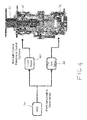
FIG. 4 is a schematic diagram of a constant speed drive (CSD) with two wobbler plates in accordance with embodiments; and -
FIG. 5 is a schematic diagram for illustrating a control law of the CSD ofFIG. 4 . - The detailed description explains embodiments of the invention, together with advantages and features, by way of example with reference to the drawings.
- The description provided below relates to a starter-drive generator (SDG) system used for starting an aircraft engine using a synchronous generator and a constant speed drive (CSD). One or more embodiments disclosed herein may allow a CSD to perform main engine start through the use of an external constant frequency power supply such as a ground cart, an auxiliary power unit (APU), etc., in addition to performing its typical frequency control function.
- With reference to
FIG. 1 , anSDG system 10 is provided for use with an aircraft or another suitable rotor-machine. TheSDG system 10 includes amain bus 11, amotor drive 12, anAC bus 13, agenerator 14, aCSD 15, a generator and CSD controller (GCC) 16 and anengine 17. As shown inFIG. 1 , one side of theAC bus 13 is connected to outputs of themain bus 11 and themotor drive 12. The other side of theAC bus 13 is connected to thegenerator 14 with the CSD 15 and theengine 17 connected to thegenerator 14 is series. The GCC 16 is disposed in parallel with thegenerator 14 and the CSD 15. - The
main bus 11 may be formed as a 3-phase AC, constant frequency bus. During a start mode of theengine 17, themain bus 11 may be connected to an external power supply (e.g., ground cart, second generator, APU, etc.). During a generate mode, the main bus may be connected to normal aircraft loads (e.g., air conditioning and electrical systems). Themotor drive 12 is used to spin thegenerator 14 to a synchronous speed, which is close to the frequency of the external power supply. Themotor drive 12 may include an active rectifier at a front end thereof and a 6-switch inverter on the back end. When themotor drive 12 is not employed forengine 17 starting operations, themotor drive 12 may be used for a secondary function such as an environmental control system (ECS) of the aircraft. TheAC bus 13 is formed as a "two-sided" panel filled with contactors and is used to re-configure power flow within the aircraft. - The
generator 14 may be a wound field synchronous generator and is configured to provide motive power for starting theengine 17 during engine start mode and to derive electrical power from theengine 17 during generate mode. During engine start, thegenerator 14 is used as a motor for theengine 17 through an ignition sequence thereof. During the generate mode, thegenerator 14 is used create electrical power based on rotational energy received from theengine 17. The CSD 15 includes a hydraulic gearbox used to regulate shaft torque between theengine 17 and thegenerator 14. The CSD 15 can be configured in an output or an input summed configuration and uses two servo valves to control torque transfer. The GCC 16 is configured to perform synchronous generator excitation control and to perform servo valve control for theCSD 15. During theengine 17 start mode, theGCC 16 regulates an exciter field in thegenerator 14 in order to help regulate torque produced by thegenerator 14 and theCSD 15. During theengine 17 generate mode, theGCC 16 regulates the exciter field to controlgenerator 14 terminal voltage. - As noted above, the
SDG system 10 may be configured to operate in two modes of operation: the start mode and the generate mode. In the start mode, external power supplied from the external constant frequency power supply via themain bus 11 is used to spin theengine 17 up to light-off speed. In the generate mode, theSDG system 10 functions in a similar fashion as existing CSD driven generators. - For the start mode, system initialization proceeds as follows. In a system initialization operation, the
AC bus 13 configures its contactors such that themotor drive 12 is connected to thegenerator 14 and themain bus 11 is disconnected from thegenerator 14. The GCC 16 supplies start mode excitation to thegenerator 14 and controls the engine shaft speed to zero RPM in accordance with an algorithm that will be described below. Themotor drive 12 then performs a precharge sequence to charge a DC link and enables a phase-lock-loop (PLL) in order to calculate a frequency and phase of a power source. - In a synchronization operation, the
motor drive 12 starts an active rectifier to generate a DC link bus. The active rectifier may include standard voltage and current regulators. Themotor drive 12 also starts a phase regulator, which controls the speed of thegenerator 14 in order to achieve the desired phase command. In a transition tomain bus 11 operation, once thegenerator 14 has achieved the desired phase command with respect to themain bus 11, themotor drive 12 is disabled, theAC bus 13 opens themotor drive 12 contactor and theAC bus 13 closes themain bus 11 contactor. In anengine 17 stating operation, with themain bus 11 contactor closed, the GCC 16 begins to accelerate theengine 17 by commanding the CSD 15 to begin applying torque to theengine 17 shaft. The GCC 16 will control the engine speed as required to start theengine 17. Finally, in a transition to generate operation, when theengine 17 achieves sufficient speed that torque assist is no longer required, theGCC 16 de-excites thegenerator 14 and re-configures the CSD 15 for generate mode. In the generate mode, theSDG system 10 function in a similar manner as conventional CSD driven generators. - With reference to
FIGS. 2 and3 , control algorithms for executing the operations described above will now be described.FIG. 2 is a top level schematic of a phase synchronization algorithm. The phase synchronization algorithm includes a phase lock loop (PLL) 20, a frequency regulator 21 (i.e., a first or frequency PI controller) and a phase regulator 22 (i.e., a second or phase PI controller). ThePLL 20 measures the AC voltage source and calculates the corresponding AC source frequency and phase. These calculated values are used as commands for thefrequency regulator 21 and thephase regulator 22. Thefrequency regulator 21 is thus enabled when a frequency error is greater than 5 Hz. Once the generator frequency is within 5 Hz of the command, thephase regulator 22 takes over and adjusts frequency in order to maintain the desired phase command. The desired phase command is adjusted by aphase advance term 23. Thephase advance term 23 is based on the amount of phase change (due to thegenerator 14 slowing down) that is expected during the power source transition from themotor drive 12 to themain bus 11. - A PLL operation algorithm is presented in
FIG. 3 . As shown inFIG. 3 , thePLL 20 reads the input AC voltages and calculates both the frequency of the AC source and the phase (or electrical angle) of the AC source. - With reference to
FIG. 4 and5 , control algorithms and operations of theCSD 15 are shown. As shown inFIG. 4 , theCSD 15 includes arotatable shaft 30 that is coupled to thegenerator 14 and theengine 17, a V-block wobbler 31 and an FV-block wobbler 32. The V-block wobbler 31 and the FV-block wobbler 32 cooperatively operate to control a rotation speed of therotatable shaft 30. The V-block wobbler 31 is operably coupled to the F-unit servo 40 and the FV-block wobbler 32 is operably coupled to the FV-unit servo 41. Both the F-unit servo 40 and the FV-unit servo are operably coupled to theGCC 16. During operation, theGCC 16 outputs electrical signals to the F-unit servo 40 and the FV-unit servo 41. Those electrical signals are converted into hydraulic control pressures that are transmitted to the V-block wobbler 31 and that FV-block wobbler 32, respectively. - That is, the
GCC 16 is responsible for controlling the torque transferred through theCSD 15. TheGCC 16 performs this by controlling the F-unit servo 40 and the FV-unit servo 41, which regulate the flow of hydraulic fluid within theCSD 15. For the purposes of the present description, theGCC 16 controls theCSD 15 through the synchronization mode, the engine start mode, the transition to generate mode and the generate mode. - During the synchronization mode, the
GCC 16 attempts to regulate the engine shaft speed (i.e., the rotatable shaft 30) to zero RPM. This is done by controlling the FV-block wobbler 32 (which is coupled to therotatable shaft 30 via a differential trim ring gear) by way of the FV-unit servo 41. This is necessary as the engine shaft may be windmilling and the motor controller may not be sized sufficiently to overcome this windmilling torque. - During the engine start mode for an input summed CSD configuration, the
GCC 16 uses the FV-unit servo 41 and the F-unit servo 40 to place the FV-block wobbler 32 on its start mode hard stop and the V-block wobbler 31 on its fully de-stroked wobbler stop, respectively. The V-block wobbler 31 is then controlled according to the control law shown inFIG. 5 while the FV-block wobbler 32 is maintained on its start mode wobbler hard stop. - During the engine start mode for an output summed CSD configuration, the FV-
block wobbler 32 is placed at a neutral (0°) wobbler angle initially and the V-block wobbler 31 is placed on its fully de-stroked wobbler stop. During the first portion of the engine start mode, the FV-block wobbler is controlled according to the control law shown inFIG. 5 while the V-block wobbler 31 is maintained on its destroke hard stop. Once the FV-block wobbler 32 hits its start mode wobbler hard stop, the V-block wobbler is controlled according to the control law shown inFIG. 5 while the FV-block wobbler 32 is maintained on its start mode hard stop. - As shown in
FIG. 5 , the servo position of each of the F-unit servo 31 and the FV-unit servo 32 is regulated using arespective PI controller 50. The input to thePI controller 50 is the calculated error between thepower command 51 and the power measured in thegenerator 14. Thepower command 51 is based on the engine shaft speed and is both rate limited byrate limiter 52 and saturated to a maximum limit by maxpower command limit 53. The feedback power provided byfeedback loop 54 is calculated using the dq voltage and current measured by theGCC 16. - During the transition to generate mode, the
GCC 16 will stroke the F-block wobbler 31 to the generate mode hard stop with the V-block wobbler 32 positioned on the fully de-stroked hard stop in preparation for the generate mode. In the generate mode, theGCC 16 will regulate the V-block wobbler 31 to control the terminal frequency as is done in conventional IDG/CSD systems. The FV-block wobbler 32 will remain on its generate mode hard stop as it is not used during the generate mode. - As a result of the use of the invention as described above, an air turbine start and engine pad can be removed to thus reduce aircraft weight, an improved start capability is provided as the engine start is electrically controlled as opposed to being controlled by a pneumatic system, the use of a constant frequency bus, as used on many aircraft and ground power carts, is permitted and a need for additional controllers on the aircraft is eliminated as functions are implemented into existing controllers.
- While the invention has been described in detail in connection with only a limited number of embodiments, it should be readily understood that the invention is not limited to such disclosed embodiments. Rather, the invention can be modified to incorporate any number of variations, alterations, substitutions or equivalent arrangements not heretofore described, but which are commensurate with the spirit and scope of the invention. Additionally, while various embodiments of the invention have been described, it is to be understood that aspects of the invention may include only some of the described embodiments. Accordingly, the invention is not to be seen as limited by the foregoing description, but is only limited by the scope of the appended claims.
Claims (15)
- A starter-drive generator (SDG) system (10) for starting an aircraft engine (17), the system comprising:a generator (14); anda constant speed drive (CSD) (15) configured to perform a main engine start through the use of an external power supply and to perform a frequency control function.
- The SDG system according to claim 1, wherein the generator (14) comprises a synchronous generator.
- The SDG system according to claim 1 or 2, wherein the external power supply comprises an external constant frequency power supply.
- The SDG system according to any preceding claim, wherein the external power supply comprises at least one of a ground cart and an auxiliary power unit.
- The SDG system according to any preceding claim, further comprising a main bus (11), which is connectable to the external power supply during an engine start mode and to normal aircraft loads during a generate mode.
- The SDG system according to any preceding claim, further comprising a motor drive (12) configured to spin the generator to a synchronous speed.
- The SDG system according to any preceding claim, further comprising an AC bus (13) configured to re-configure power flow within the aircraft.
- The SDG system according to any preceding claim, wherein the CSD comprises:a V-block wobbler (31) and an FV-block wobbler (32);an F-unit servo (40) to control an operation of the V-block wobbler (31); andan FV-unit servo (41) to control an operation of the FV-block wobbler (32).
- The SDG system according to any preceding claim, further comprising a generator and CSD controller (GCC) (16), which is configured to regulate torque produced by the generator (14) and the CSD (15) during an engine start mode and to control a generator terminal voltage during a generate mode.
- The SDG system according to any of claims 1 to 8, wherein the generator (14) provides motive power for starting the aircraft engine (17) during an engine start mode and derives electrical power from rotation of the engine during a generate mode;
the constant speed drive transmits motive power from the engine to the generator (14) during a generate mode; and
further comprising:a generator and CSD controller (GCC) (16) coupled to the generator (14) and the CSD (15), which is configured to regulate transmission of the motive power between the generator (14) and the engine (17) to execute at least the engine start mode and the generate mode. - A starter-drive generator (SDG) system (10) for starting an aircraft engine (17), the system comprising:a generator (14) to provide motive power for starting an engine (17) during an engine start mode and to derive electrical power from rotation of the engine during a generate mode;a constant speed drive (CSD) (15) to transmit the motive power from the engine to the generator (14) during the generate mode; anda generator and CSD controller (GCC) (16) coupled to the generator (14) and the CSD (15), which is configured to regulate transmission of the motive power between the generator (14) and the engine (17) to execute at least the engine start mode and the generate mode.
- The SDG system according to claim 11, further comprising a motor drive (12) configured to spin the generator (14) to a synchronous speed.
- The SDG system according to claim 11 or 12, further comprising an AC bus (13) configured to re-configure power flow within the aircraft.
- The SDG system according to claim 11, 12 or 13, wherein the CSD (15) comprises:a V-block wobbler (31) and an FV-block wobbler (32);an F-unit servo (40) to control an operation of the V-block wobbler (31); andan FV-unit servo (41) to control an operation of the FV-block wobbler (32).
- The SDG system according to any of claims 11 to 14, wherein the generator and CSD controller (GCC) (16), is configured to regulate torque produced by the generator (14) and the CSD (15) during the engine start mode and to control a generator terminal voltage during the generate mode.
Applications Claiming Priority (1)
| Application Number | Priority Date | Filing Date | Title |
|---|---|---|---|
| US13/761,706 US8742605B1 (en) | 2013-02-07 | 2013-02-07 | Method for aircraft engine start using synchronous generator and constant speed drive |
Publications (3)
| Publication Number | Publication Date |
|---|---|
| EP2765304A2 true EP2765304A2 (en) | 2014-08-13 |
| EP2765304A3 EP2765304A3 (en) | 2015-04-15 |
| EP2765304B1 EP2765304B1 (en) | 2020-04-08 |
Family
ID=50064519
Family Applications (1)
| Application Number | Title | Priority Date | Filing Date |
|---|---|---|---|
| EP14154391.8A Active EP2765304B1 (en) | 2013-02-07 | 2014-02-07 | A starter-drive generator system for starting an aircraft engine |
Country Status (2)
| Country | Link |
|---|---|
| US (1) | US8742605B1 (en) |
| EP (1) | EP2765304B1 (en) |
Families Citing this family (22)
| Publication number | Priority date | Publication date | Assignee | Title |
|---|---|---|---|---|
| US9835160B2 (en) | 2014-12-08 | 2017-12-05 | General Electric Company | Systems and methods for energy optimization for converterless motor-driven pumps |
| US10000293B2 (en) | 2015-01-23 | 2018-06-19 | General Electric Company | Gas-electric propulsion system for an aircraft |
| US10087902B2 (en) | 2015-05-11 | 2018-10-02 | Sikorsky Aircraft Corporation | Power limiting generator control unit (GCU) |
| BR112017026360B1 (en) | 2015-06-08 | 2023-01-17 | Hamilton Sundstrand Corporation | PLANE |
| US9938853B2 (en) | 2015-10-23 | 2018-04-10 | General Electric Company | Torsional damping for gas turbine engines |
| US9764848B1 (en) | 2016-03-07 | 2017-09-19 | General Electric Company | Propulsion system for an aircraft |
| US10612824B2 (en) | 2016-05-06 | 2020-04-07 | Hamilton Sundstrand Corporation | Gas-liquid phase separator |
| US10071811B2 (en) | 2016-08-22 | 2018-09-11 | General Electric Company | Embedded electric machine |
| US10487839B2 (en) | 2016-08-22 | 2019-11-26 | General Electric Company | Embedded electric machine |
| US10093428B2 (en) | 2016-08-22 | 2018-10-09 | General Electric Company | Electric propulsion system |
| US10308366B2 (en) | 2016-08-22 | 2019-06-04 | General Electric Company | Embedded electric machine |
| US10934885B2 (en) | 2016-11-07 | 2021-03-02 | Raytheon Technologies Corporation | System and method for controlling dual starter air valve |
| US10793281B2 (en) | 2017-02-10 | 2020-10-06 | General Electric Company | Propulsion system for an aircraft |
| US10822103B2 (en) | 2017-02-10 | 2020-11-03 | General Electric Company | Propulsor assembly for an aircraft |
| US11149578B2 (en) | 2017-02-10 | 2021-10-19 | General Electric Company | Propulsion system for an aircraft |
| US10762726B2 (en) | 2017-06-13 | 2020-09-01 | General Electric Company | Hybrid-electric propulsion system for an aircraft |
| US11273927B2 (en) | 2018-04-04 | 2022-03-15 | Honeywell International Inc. | Micro-auxiliary power units |
| US11156128B2 (en) | 2018-08-22 | 2021-10-26 | General Electric Company | Embedded electric machine |
| US11097849B2 (en) | 2018-09-10 | 2021-08-24 | General Electric Company | Aircraft having an aft engine |
| US11539316B2 (en) | 2019-07-30 | 2022-12-27 | General Electric Company | Active stability control of compression systems utilizing electric machines |
| US12149154B2 (en) | 2021-07-22 | 2024-11-19 | General Electric Company | Electric machine having a hybrid insulative-conductive manifold |
| US11697998B1 (en) | 2022-04-08 | 2023-07-11 | Hamilton Sundstrand Corporation | Constant speed drive to control variable APU speed and constant generator output frequency |
Family Cites Families (29)
| Publication number | Priority date | Publication date | Assignee | Title |
|---|---|---|---|---|
| US4401938A (en) * | 1980-12-29 | 1983-08-30 | Lockheed Corporation | Variable-speed drive for control of induction generators |
| US4488198A (en) * | 1981-01-15 | 1984-12-11 | Sundstrand Corporation | Protective circuit for clutchless parallel generating system |
| US4382188A (en) * | 1981-02-17 | 1983-05-03 | Lockheed Corporation | Dual-range drive configurations for synchronous and induction generators |
| US4488053A (en) * | 1981-02-17 | 1984-12-11 | Lockheed Corporation | Electric constant speed/variable speed drive/generator assembly |
| US4694187A (en) * | 1986-01-13 | 1987-09-15 | Westinghouse Electric Corp. | Electromechanical constant speed drive generating system |
| US4786852A (en) | 1986-07-18 | 1988-11-22 | Sundstrand Corporation | Inverter operated turbine engine starting system |
| US4743776A (en) | 1986-09-02 | 1988-05-10 | Sundstrand Corporation | Starter-generator for engines |
| US4697090A (en) * | 1986-12-23 | 1987-09-29 | Sundstrand Corporation | Starting system for an electrically-compensated constant speed drive |
| US4772802A (en) | 1987-08-19 | 1988-09-20 | Sundstrand Corporation | Starting/generating system |
| US4817459A (en) | 1987-12-24 | 1989-04-04 | Sundstrand Corporation | Engine starting and power generating system |
| US4868406A (en) | 1988-07-05 | 1989-09-19 | Sundstrand Corporation | Electrically compensated constant speed drive with prime mover start capability |
| US7905813B2 (en) * | 1999-09-28 | 2011-03-15 | Borealis Technical Limited | Electronically controlled engine generator set |
| US6825575B1 (en) * | 1999-09-28 | 2004-11-30 | Borealis Technical Limited | Electronically controlled engine generator set |
| US6462429B1 (en) * | 2000-02-24 | 2002-10-08 | Hamilton Sundstrand Corporation | Induction motor/generator system |
| EP1167838A1 (en) | 2000-06-30 | 2002-01-02 | Van Doorne's Transmissie B.V. | Hydraulically controllable constant speed drive and method for the design thereof |
| GB0016182D0 (en) * | 2000-06-30 | 2000-08-23 | Lucas Industries Ltd | Controller for a continuously variable transmission |
| US6707205B2 (en) | 2001-07-16 | 2004-03-16 | Hamilton Sundstrand Corporation | High-speed, high-power rotary electrodynamic machine with dual rotors |
| US6838778B1 (en) | 2002-05-24 | 2005-01-04 | Hamilton Sundstrand Corporation | Integrated starter generator drive having selective torque converter and constant speed transmission for aircraft having a constant frequency electrical system |
| US7105937B2 (en) | 2004-07-14 | 2006-09-12 | Hamilton Sundstrand Corporation | Adjustable variable frequency starter/generator system |
| US7250688B2 (en) * | 2004-07-14 | 2007-07-31 | Hamilton Sundstrand Corporation | Narrow range variable frequency starter/generator system |
| US7434406B2 (en) | 2005-05-10 | 2008-10-14 | Honeywell International Inc. | Drive for using a direct driven generator to start a counter-rotating multi-spool gas turbine engine |
| US7805947B2 (en) | 2005-05-19 | 2010-10-05 | Djamal Moulebhar | Aircraft with disengageable engine and auxiliary power unit components |
| NO326634B1 (en) * | 2006-09-12 | 2009-01-26 | Aker Engineering & Technology | Method and system for starting and operating an electrically driven load |
| US7405542B1 (en) | 2006-12-20 | 2008-07-29 | The Boeing Company | Generator synchronization method on a common drive source and apparatus therefor |
| US7514806B2 (en) * | 2007-06-05 | 2009-04-07 | Honeywell International Inc. | Engine start system with quadrature AC excitation |
| US7687927B2 (en) * | 2007-11-21 | 2010-03-30 | The Boeing Company | Electrical systems architecture for an aircraft, and related operating methods |
| US8250854B2 (en) | 2007-12-05 | 2012-08-28 | Sharpe Thomas H | Self-starting turbineless jet engine |
| US8039983B2 (en) * | 2008-12-02 | 2011-10-18 | The Boeing Company | Systems and methods for providing AC power from multiple turbine engine spools |
| US8049386B2 (en) | 2009-05-08 | 2011-11-01 | Hamilton Sundstrand Corporation | Seal cartridge |
-
2013
- 2013-02-07 US US13/761,706 patent/US8742605B1/en active Active
-
2014
- 2014-02-07 EP EP14154391.8A patent/EP2765304B1/en active Active
Non-Patent Citations (1)
| Title |
|---|
| None |
Also Published As
| Publication number | Publication date |
|---|---|
| EP2765304B1 (en) | 2020-04-08 |
| EP2765304A3 (en) | 2015-04-15 |
| US8742605B1 (en) | 2014-06-03 |
Similar Documents
| Publication | Publication Date | Title |
|---|---|---|
| US8742605B1 (en) | Method for aircraft engine start using synchronous generator and constant speed drive | |
| JP6318256B2 (en) | Gas turbine power generation system | |
| CN101636899B (en) | High Voltage DC Link Transmission System for Variable Speed Wind Turbines | |
| EP1007844B1 (en) | Variable speed wind turbine generator | |
| US6600240B2 (en) | Variable speed wind turbine generator | |
| CN101353043B (en) | Clutch engaging control method and control system for hybrid power output device | |
| US20190173403A1 (en) | Multiple generator synchronous electrical power distribution system | |
| US10263550B2 (en) | Gas turbine power generation system and control system used in the same | |
| EP3375981A1 (en) | Variable speed ac bus powered tail cone boundary layer ingestion thruster | |
| US20160340051A1 (en) | Aircraft electrical network | |
| CN119042068B (en) | Coordinated control system for variable speed pumped storage units | |
| EP3487063A1 (en) | Independent speed variable frequency alternating current generator | |
| JP2013537789A (en) | Renewable energy power generator and method of operating the same | |
| JP2019522589A (en) | Method for controlling components of a hybrid transmission for a motor vehicle | |
| JP3647816B2 (en) | Synchronous charging control method and apparatus | |
| JPS6271497A (en) | Controller for variable-speed hydraulic turbine generator | |
| US20200198795A1 (en) | Device For Providing Power Or Thrust To An Aerospace Vehicle And Method For Controlling A Device For Providing Power To An Aerospace Vehicle | |
| US9450527B2 (en) | Controlled frequency generator with optimized power factor | |
| CN113839597B (en) | Methods for starting and synchronously running motors powered by different power supplies | |
| AU2004220762B2 (en) | Variable speed wind turbine generator | |
| AU774980B2 (en) | Variable speed wind turbine generator | |
| CN120934024A (en) | Inertia flywheel system based on permanent magnet brushless electromagnetic coupler and control method thereof | |
| MXPA00001375A (en) | Variable speed wind turbine generator |
Legal Events
| Date | Code | Title | Description |
|---|---|---|---|
| PUAI | Public reference made under article 153(3) epc to a published international application that has entered the european phase |
Free format text: ORIGINAL CODE: 0009012 |
|
| 17P | Request for examination filed |
Effective date: 20140207 |
|
| AK | Designated contracting states |
Kind code of ref document: A2 Designated state(s): AL AT BE BG CH CY CZ DE DK EE ES FI FR GB GR HR HU IE IS IT LI LT LU LV MC MK MT NL NO PL PT RO RS SE SI SK SM TR |
|
| AX | Request for extension of the european patent |
Extension state: BA ME |
|
| PUAL | Search report despatched |
Free format text: ORIGINAL CODE: 0009013 |
|
| AK | Designated contracting states |
Kind code of ref document: A3 Designated state(s): AL AT BE BG CH CY CZ DE DK EE ES FI FR GB GR HR HU IE IS IT LI LT LU LV MC MK MT NL NO PL PT RO RS SE SI SK SM TR |
|
| AX | Request for extension of the european patent |
Extension state: BA ME |
|
| RIC1 | Information provided on ipc code assigned before grant |
Ipc: F02N 11/04 20060101AFI20150311BHEP Ipc: F02C 7/275 20060101ALI20150311BHEP Ipc: F02C 7/26 20060101ALI20150311BHEP |
|
| R17P | Request for examination filed (corrected) |
Effective date: 20151015 |
|
| RBV | Designated contracting states (corrected) |
Designated state(s): AL AT BE BG CH CY CZ DE DK EE ES FI FR GB GR HR HU IE IS IT LI LT LU LV MC MK MT NL NO PL PT RO RS SE SI SK SM TR |
|
| STAA | Information on the status of an ep patent application or granted ep patent |
Free format text: STATUS: EXAMINATION IS IN PROGRESS |
|
| 17Q | First examination report despatched |
Effective date: 20180713 |
|
| GRAP | Despatch of communication of intention to grant a patent |
Free format text: ORIGINAL CODE: EPIDOSNIGR1 |
|
| STAA | Information on the status of an ep patent application or granted ep patent |
Free format text: STATUS: GRANT OF PATENT IS INTENDED |
|
| INTG | Intention to grant announced |
Effective date: 20191014 |
|
| GRAS | Grant fee paid |
Free format text: ORIGINAL CODE: EPIDOSNIGR3 |
|
| RAP1 | Party data changed (applicant data changed or rights of an application transferred) |
Owner name: HAMILTON SUNDSTRAND CORPORATION |
|
| GRAA | (expected) grant |
Free format text: ORIGINAL CODE: 0009210 |
|
| STAA | Information on the status of an ep patent application or granted ep patent |
Free format text: STATUS: THE PATENT HAS BEEN GRANTED |
|
| AK | Designated contracting states |
Kind code of ref document: B1 Designated state(s): AL AT BE BG CH CY CZ DE DK EE ES FI FR GB GR HR HU IE IS IT LI LT LU LV MC MK MT NL NO PL PT RO RS SE SI SK SM TR |
|
| REG | Reference to a national code |
Ref country code: AT Ref legal event code: REF Ref document number: 1254719 Country of ref document: AT Kind code of ref document: T Effective date: 20200415 Ref country code: CH Ref legal event code: EP |
|
| REG | Reference to a national code |
Ref country code: DE Ref legal event code: R096 Ref document number: 602014063386 Country of ref document: DE |
|
| REG | Reference to a national code |
Ref country code: IE Ref legal event code: FG4D |
|
| REG | Reference to a national code |
Ref country code: NL Ref legal event code: MP Effective date: 20200408 |
|
| REG | Reference to a national code |
Ref country code: LT Ref legal event code: MG4D |
|
| PG25 | Lapsed in a contracting state [announced via postgrant information from national office to epo] |
Ref country code: FI Free format text: LAPSE BECAUSE OF FAILURE TO SUBMIT A TRANSLATION OF THE DESCRIPTION OR TO PAY THE FEE WITHIN THE PRESCRIBED TIME-LIMIT Effective date: 20200408 Ref country code: NL Free format text: LAPSE BECAUSE OF FAILURE TO SUBMIT A TRANSLATION OF THE DESCRIPTION OR TO PAY THE FEE WITHIN THE PRESCRIBED TIME-LIMIT Effective date: 20200408 Ref country code: SE Free format text: LAPSE BECAUSE OF FAILURE TO SUBMIT A TRANSLATION OF THE DESCRIPTION OR TO PAY THE FEE WITHIN THE PRESCRIBED TIME-LIMIT Effective date: 20200408 Ref country code: LT Free format text: LAPSE BECAUSE OF FAILURE TO SUBMIT A TRANSLATION OF THE DESCRIPTION OR TO PAY THE FEE WITHIN THE PRESCRIBED TIME-LIMIT Effective date: 20200408 Ref country code: PT Free format text: LAPSE BECAUSE OF FAILURE TO SUBMIT A TRANSLATION OF THE DESCRIPTION OR TO PAY THE FEE WITHIN THE PRESCRIBED TIME-LIMIT Effective date: 20200817 Ref country code: NO Free format text: LAPSE BECAUSE OF FAILURE TO SUBMIT A TRANSLATION OF THE DESCRIPTION OR TO PAY THE FEE WITHIN THE PRESCRIBED TIME-LIMIT Effective date: 20200708 Ref country code: GR Free format text: LAPSE BECAUSE OF FAILURE TO SUBMIT A TRANSLATION OF THE DESCRIPTION OR TO PAY THE FEE WITHIN THE PRESCRIBED TIME-LIMIT Effective date: 20200709 Ref country code: IS Free format text: LAPSE BECAUSE OF FAILURE TO SUBMIT A TRANSLATION OF THE DESCRIPTION OR TO PAY THE FEE WITHIN THE PRESCRIBED TIME-LIMIT Effective date: 20200808 |
|
| REG | Reference to a national code |
Ref country code: AT Ref legal event code: MK05 Ref document number: 1254719 Country of ref document: AT Kind code of ref document: T Effective date: 20200408 |
|
| PG25 | Lapsed in a contracting state [announced via postgrant information from national office to epo] |
Ref country code: RS Free format text: LAPSE BECAUSE OF FAILURE TO SUBMIT A TRANSLATION OF THE DESCRIPTION OR TO PAY THE FEE WITHIN THE PRESCRIBED TIME-LIMIT Effective date: 20200408 Ref country code: LV Free format text: LAPSE BECAUSE OF FAILURE TO SUBMIT A TRANSLATION OF THE DESCRIPTION OR TO PAY THE FEE WITHIN THE PRESCRIBED TIME-LIMIT Effective date: 20200408 Ref country code: HR Free format text: LAPSE BECAUSE OF FAILURE TO SUBMIT A TRANSLATION OF THE DESCRIPTION OR TO PAY THE FEE WITHIN THE PRESCRIBED TIME-LIMIT Effective date: 20200408 Ref country code: BG Free format text: LAPSE BECAUSE OF FAILURE TO SUBMIT A TRANSLATION OF THE DESCRIPTION OR TO PAY THE FEE WITHIN THE PRESCRIBED TIME-LIMIT Effective date: 20200708 |
|
| PG25 | Lapsed in a contracting state [announced via postgrant information from national office to epo] |
Ref country code: AL Free format text: LAPSE BECAUSE OF FAILURE TO SUBMIT A TRANSLATION OF THE DESCRIPTION OR TO PAY THE FEE WITHIN THE PRESCRIBED TIME-LIMIT Effective date: 20200408 |
|
| REG | Reference to a national code |
Ref country code: DE Ref legal event code: R097 Ref document number: 602014063386 Country of ref document: DE |
|
| PG25 | Lapsed in a contracting state [announced via postgrant information from national office to epo] |
Ref country code: AT Free format text: LAPSE BECAUSE OF FAILURE TO SUBMIT A TRANSLATION OF THE DESCRIPTION OR TO PAY THE FEE WITHIN THE PRESCRIBED TIME-LIMIT Effective date: 20200408 Ref country code: SM Free format text: LAPSE BECAUSE OF FAILURE TO SUBMIT A TRANSLATION OF THE DESCRIPTION OR TO PAY THE FEE WITHIN THE PRESCRIBED TIME-LIMIT Effective date: 20200408 Ref country code: EE Free format text: LAPSE BECAUSE OF FAILURE TO SUBMIT A TRANSLATION OF THE DESCRIPTION OR TO PAY THE FEE WITHIN THE PRESCRIBED TIME-LIMIT Effective date: 20200408 Ref country code: RO Free format text: LAPSE BECAUSE OF FAILURE TO SUBMIT A TRANSLATION OF THE DESCRIPTION OR TO PAY THE FEE WITHIN THE PRESCRIBED TIME-LIMIT Effective date: 20200408 Ref country code: IT Free format text: LAPSE BECAUSE OF FAILURE TO SUBMIT A TRANSLATION OF THE DESCRIPTION OR TO PAY THE FEE WITHIN THE PRESCRIBED TIME-LIMIT Effective date: 20200408 Ref country code: CZ Free format text: LAPSE BECAUSE OF FAILURE TO SUBMIT A TRANSLATION OF THE DESCRIPTION OR TO PAY THE FEE WITHIN THE PRESCRIBED TIME-LIMIT Effective date: 20200408 Ref country code: ES Free format text: LAPSE BECAUSE OF FAILURE TO SUBMIT A TRANSLATION OF THE DESCRIPTION OR TO PAY THE FEE WITHIN THE PRESCRIBED TIME-LIMIT Effective date: 20200408 Ref country code: DK Free format text: LAPSE BECAUSE OF FAILURE TO SUBMIT A TRANSLATION OF THE DESCRIPTION OR TO PAY THE FEE WITHIN THE PRESCRIBED TIME-LIMIT Effective date: 20200408 |
|
| PLBE | No opposition filed within time limit |
Free format text: ORIGINAL CODE: 0009261 |
|
| STAA | Information on the status of an ep patent application or granted ep patent |
Free format text: STATUS: NO OPPOSITION FILED WITHIN TIME LIMIT |
|
| PG25 | Lapsed in a contracting state [announced via postgrant information from national office to epo] |
Ref country code: SK Free format text: LAPSE BECAUSE OF FAILURE TO SUBMIT A TRANSLATION OF THE DESCRIPTION OR TO PAY THE FEE WITHIN THE PRESCRIBED TIME-LIMIT Effective date: 20200408 Ref country code: PL Free format text: LAPSE BECAUSE OF FAILURE TO SUBMIT A TRANSLATION OF THE DESCRIPTION OR TO PAY THE FEE WITHIN THE PRESCRIBED TIME-LIMIT Effective date: 20200408 |
|
| 26N | No opposition filed |
Effective date: 20210112 |
|
| PG25 | Lapsed in a contracting state [announced via postgrant information from national office to epo] |
Ref country code: SI Free format text: LAPSE BECAUSE OF FAILURE TO SUBMIT A TRANSLATION OF THE DESCRIPTION OR TO PAY THE FEE WITHIN THE PRESCRIBED TIME-LIMIT Effective date: 20200408 |
|
| REG | Reference to a national code |
Ref country code: DE Ref legal event code: R119 Ref document number: 602014063386 Country of ref document: DE |
|
| PG25 | Lapsed in a contracting state [announced via postgrant information from national office to epo] |
Ref country code: MC Free format text: LAPSE BECAUSE OF FAILURE TO SUBMIT A TRANSLATION OF THE DESCRIPTION OR TO PAY THE FEE WITHIN THE PRESCRIBED TIME-LIMIT Effective date: 20200408 |
|
| REG | Reference to a national code |
Ref country code: BE Ref legal event code: MM Effective date: 20210228 |
|
| PG25 | Lapsed in a contracting state [announced via postgrant information from national office to epo] |
Ref country code: LI Free format text: LAPSE BECAUSE OF NON-PAYMENT OF DUE FEES Effective date: 20210228 Ref country code: LU Free format text: LAPSE BECAUSE OF NON-PAYMENT OF DUE FEES Effective date: 20210207 Ref country code: CH Free format text: LAPSE BECAUSE OF NON-PAYMENT OF DUE FEES Effective date: 20210228 |
|
| PG25 | Lapsed in a contracting state [announced via postgrant information from national office to epo] |
Ref country code: DE Free format text: LAPSE BECAUSE OF NON-PAYMENT OF DUE FEES Effective date: 20210901 Ref country code: IE Free format text: LAPSE BECAUSE OF NON-PAYMENT OF DUE FEES Effective date: 20210207 |
|
| PG25 | Lapsed in a contracting state [announced via postgrant information from national office to epo] |
Ref country code: BE Free format text: LAPSE BECAUSE OF NON-PAYMENT OF DUE FEES Effective date: 20210228 |
|
| PG25 | Lapsed in a contracting state [announced via postgrant information from national office to epo] |
Ref country code: HU Free format text: LAPSE BECAUSE OF FAILURE TO SUBMIT A TRANSLATION OF THE DESCRIPTION OR TO PAY THE FEE WITHIN THE PRESCRIBED TIME-LIMIT; INVALID AB INITIO Effective date: 20140207 |
|
| P01 | Opt-out of the competence of the unified patent court (upc) registered |
Effective date: 20230522 |
|
| PG25 | Lapsed in a contracting state [announced via postgrant information from national office to epo] |
Ref country code: CY Free format text: LAPSE BECAUSE OF FAILURE TO SUBMIT A TRANSLATION OF THE DESCRIPTION OR TO PAY THE FEE WITHIN THE PRESCRIBED TIME-LIMIT Effective date: 20200408 |
|
| PG25 | Lapsed in a contracting state [announced via postgrant information from national office to epo] |
Ref country code: MK Free format text: LAPSE BECAUSE OF FAILURE TO SUBMIT A TRANSLATION OF THE DESCRIPTION OR TO PAY THE FEE WITHIN THE PRESCRIBED TIME-LIMIT Effective date: 20200408 |
|
| PG25 | Lapsed in a contracting state [announced via postgrant information from national office to epo] |
Ref country code: TR Free format text: LAPSE BECAUSE OF FAILURE TO SUBMIT A TRANSLATION OF THE DESCRIPTION OR TO PAY THE FEE WITHIN THE PRESCRIBED TIME-LIMIT Effective date: 20200408 |
|
| PG25 | Lapsed in a contracting state [announced via postgrant information from national office to epo] |
Ref country code: MT Free format text: LAPSE BECAUSE OF FAILURE TO SUBMIT A TRANSLATION OF THE DESCRIPTION OR TO PAY THE FEE WITHIN THE PRESCRIBED TIME-LIMIT Effective date: 20200408 |
|
| PGFP | Annual fee paid to national office [announced via postgrant information from national office to epo] |
Ref country code: GB Payment date: 20260122 Year of fee payment: 13 |
|
| PGFP | Annual fee paid to national office [announced via postgrant information from national office to epo] |
Ref country code: FR Payment date: 20260121 Year of fee payment: 13 |