EP2764858A1 - Vibrating stimulus pad - Google Patents
Vibrating stimulus pad Download PDFInfo
- Publication number
- EP2764858A1 EP2764858A1 EP20120850118 EP12850118A EP2764858A1 EP 2764858 A1 EP2764858 A1 EP 2764858A1 EP 20120850118 EP20120850118 EP 20120850118 EP 12850118 A EP12850118 A EP 12850118A EP 2764858 A1 EP2764858 A1 EP 2764858A1
- Authority
- EP
- European Patent Office
- Prior art keywords
- pad
- attached
- adhesive
- vibrating stimulus
- vibrating
- Prior art date
- Legal status (The legal status is an assumption and is not a legal conclusion. Google has not performed a legal analysis and makes no representation as to the accuracy of the status listed.)
- Granted
Links
- 239000000853 adhesive Substances 0.000 claims abstract description 26
- 230000001070 adhesive effect Effects 0.000 claims abstract description 26
- 239000003814 drug Substances 0.000 claims abstract description 23
- 229940079593 drug Drugs 0.000 claims abstract description 12
- 229940035676 analgesics Drugs 0.000 claims abstract description 5
- 239000000730 antalgic agent Substances 0.000 claims abstract description 5
- 230000003110 anti-inflammatory effect Effects 0.000 claims abstract description 5
- 229940124599 anti-inflammatory drug Drugs 0.000 claims description 4
- 239000000463 material Substances 0.000 abstract description 6
- 210000000746 body region Anatomy 0.000 abstract 2
- 206010025482 malaise Diseases 0.000 abstract 2
- 239000000654 additive Substances 0.000 abstract 1
- 230000000996 additive effect Effects 0.000 abstract 1
- 239000010410 layer Substances 0.000 description 20
- 238000005452 bending Methods 0.000 description 6
- 238000000554 physical therapy Methods 0.000 description 5
- 208000002193 Pain Diseases 0.000 description 4
- 230000036407 pain Effects 0.000 description 4
- 241000252254 Catostomidae Species 0.000 description 2
- 239000012790 adhesive layer Substances 0.000 description 2
- 239000004745 nonwoven fabric Substances 0.000 description 2
- 229940124595 oriental medicine Drugs 0.000 description 2
- 238000000926 separation method Methods 0.000 description 2
- 229940126673 western medicines Drugs 0.000 description 2
- 208000006820 Arthralgia Diseases 0.000 description 1
- 208000000112 Myalgia Diseases 0.000 description 1
- 230000037374 absorbed through the skin Effects 0.000 description 1
- 238000007792 addition Methods 0.000 description 1
- 239000011248 coating agent Substances 0.000 description 1
- 238000000576 coating method Methods 0.000 description 1
- 230000003247 decreasing effect Effects 0.000 description 1
- 230000000694 effects Effects 0.000 description 1
- 229920002457 flexible plastic Polymers 0.000 description 1
- 238000002347 injection Methods 0.000 description 1
- 239000007924 injection Substances 0.000 description 1
- 230000000116 mitigating effect Effects 0.000 description 1
- 230000004048 modification Effects 0.000 description 1
- 238000012986 modification Methods 0.000 description 1
- 239000012466 permeate Substances 0.000 description 1
- 230000037081 physical activity Effects 0.000 description 1
- 239000000047 product Substances 0.000 description 1
- 229910052710 silicon Inorganic materials 0.000 description 1
- 239000010703 silicon Substances 0.000 description 1
- 239000000243 solution Substances 0.000 description 1
- 238000006467 substitution reaction Methods 0.000 description 1
- 208000024891 symptom Diseases 0.000 description 1
Images
Classifications
-
- A—HUMAN NECESSITIES
- A61—MEDICAL OR VETERINARY SCIENCE; HYGIENE
- A61H—PHYSICAL THERAPY APPARATUS, e.g. DEVICES FOR LOCATING OR STIMULATING REFLEX POINTS IN THE BODY; ARTIFICIAL RESPIRATION; MASSAGE; BATHING DEVICES FOR SPECIAL THERAPEUTIC OR HYGIENIC PURPOSES OR SPECIFIC PARTS OF THE BODY
- A61H23/00—Percussion or vibration massage, e.g. using supersonic vibration; Suction-vibration massage; Massage with moving diaphragms
- A61H23/02—Percussion or vibration massage, e.g. using supersonic vibration; Suction-vibration massage; Massage with moving diaphragms with electric or magnetic drive
-
- A—HUMAN NECESSITIES
- A61—MEDICAL OR VETERINARY SCIENCE; HYGIENE
- A61F—FILTERS IMPLANTABLE INTO BLOOD VESSELS; PROSTHESES; DEVICES PROVIDING PATENCY TO, OR PREVENTING COLLAPSING OF, TUBULAR STRUCTURES OF THE BODY, e.g. STENTS; ORTHOPAEDIC, NURSING OR CONTRACEPTIVE DEVICES; FOMENTATION; TREATMENT OR PROTECTION OF EYES OR EARS; BANDAGES, DRESSINGS OR ABSORBENT PADS; FIRST-AID KITS
- A61F7/00—Heating or cooling appliances for medical or therapeutic treatment of the human body
- A61F7/02—Compresses or poultices for effecting heating or cooling
-
- A—HUMAN NECESSITIES
- A61—MEDICAL OR VETERINARY SCIENCE; HYGIENE
- A61F—FILTERS IMPLANTABLE INTO BLOOD VESSELS; PROSTHESES; DEVICES PROVIDING PATENCY TO, OR PREVENTING COLLAPSING OF, TUBULAR STRUCTURES OF THE BODY, e.g. STENTS; ORTHOPAEDIC, NURSING OR CONTRACEPTIVE DEVICES; FOMENTATION; TREATMENT OR PROTECTION OF EYES OR EARS; BANDAGES, DRESSINGS OR ABSORBENT PADS; FIRST-AID KITS
- A61F7/00—Heating or cooling appliances for medical or therapeutic treatment of the human body
- A61F7/02—Compresses or poultices for effecting heating or cooling
- A61F7/03—Compresses or poultices for effecting heating or cooling thermophore, i.e. self-heating, e.g. using a chemical reaction
- A61F7/032—Compresses or poultices for effecting heating or cooling thermophore, i.e. self-heating, e.g. using a chemical reaction using oxygen from the air, e.g. pocket-stoves
- A61F7/034—Flameless
-
- A—HUMAN NECESSITIES
- A61—MEDICAL OR VETERINARY SCIENCE; HYGIENE
- A61K—PREPARATIONS FOR MEDICAL, DENTAL OR TOILETRY PURPOSES
- A61K9/00—Medicinal preparations characterised by special physical form
- A61K9/70—Web, sheet or filament bases ; Films; Fibres of the matrix type containing drug
-
- A—HUMAN NECESSITIES
- A61—MEDICAL OR VETERINARY SCIENCE; HYGIENE
- A61N—ELECTROTHERAPY; MAGNETOTHERAPY; RADIATION THERAPY; ULTRASOUND THERAPY
- A61N1/00—Electrotherapy; Circuits therefor
- A61N1/02—Details
- A61N1/04—Electrodes
- A61N1/0404—Electrodes for external use
- A61N1/0472—Structure-related aspects
- A61N1/0492—Patch electrodes
-
- A—HUMAN NECESSITIES
- A61—MEDICAL OR VETERINARY SCIENCE; HYGIENE
- A61H—PHYSICAL THERAPY APPARATUS, e.g. DEVICES FOR LOCATING OR STIMULATING REFLEX POINTS IN THE BODY; ARTIFICIAL RESPIRATION; MASSAGE; BATHING DEVICES FOR SPECIAL THERAPEUTIC OR HYGIENIC PURPOSES OR SPECIFIC PARTS OF THE BODY
- A61H2201/00—Characteristics of apparatus not provided for in the preceding codes
- A61H2201/02—Characteristics of apparatus not provided for in the preceding codes heated or cooled
- A61H2201/0207—Characteristics of apparatus not provided for in the preceding codes heated or cooled heated
-
- A—HUMAN NECESSITIES
- A61—MEDICAL OR VETERINARY SCIENCE; HYGIENE
- A61H—PHYSICAL THERAPY APPARATUS, e.g. DEVICES FOR LOCATING OR STIMULATING REFLEX POINTS IN THE BODY; ARTIFICIAL RESPIRATION; MASSAGE; BATHING DEVICES FOR SPECIAL THERAPEUTIC OR HYGIENIC PURPOSES OR SPECIFIC PARTS OF THE BODY
- A61H2201/00—Characteristics of apparatus not provided for in the preceding codes
- A61H2201/02—Characteristics of apparatus not provided for in the preceding codes heated or cooled
- A61H2201/0221—Mechanism for heating or cooling
- A61H2201/0228—Mechanism for heating or cooling heated by an electric resistance element
-
- A—HUMAN NECESSITIES
- A61—MEDICAL OR VETERINARY SCIENCE; HYGIENE
- A61H—PHYSICAL THERAPY APPARATUS, e.g. DEVICES FOR LOCATING OR STIMULATING REFLEX POINTS IN THE BODY; ARTIFICIAL RESPIRATION; MASSAGE; BATHING DEVICES FOR SPECIAL THERAPEUTIC OR HYGIENIC PURPOSES OR SPECIFIC PARTS OF THE BODY
- A61H2201/00—Characteristics of apparatus not provided for in the preceding codes
- A61H2201/16—Physical interface with patient
- A61H2201/1602—Physical interface with patient kind of interface, e.g. head rest, knee support or lumbar support
- A61H2201/165—Wearable interfaces
-
- A—HUMAN NECESSITIES
- A61—MEDICAL OR VETERINARY SCIENCE; HYGIENE
- A61K—PREPARATIONS FOR MEDICAL, DENTAL OR TOILETRY PURPOSES
- A61K9/00—Medicinal preparations characterised by special physical form
- A61K9/70—Web, sheet or filament bases ; Films; Fibres of the matrix type containing drug
- A61K9/7023—Transdermal patches and similar drug-containing composite devices, e.g. cataplasms
- A61K9/703—Transdermal patches and similar drug-containing composite devices, e.g. cataplasms characterised by shape or structure; Details concerning release liner or backing; Refillable patches; User-activated patches
- A61K9/7038—Transdermal patches of the drug-in-adhesive type, i.e. comprising drug in the skin-adhesive layer
-
- A—HUMAN NECESSITIES
- A61—MEDICAL OR VETERINARY SCIENCE; HYGIENE
- A61N—ELECTROTHERAPY; MAGNETOTHERAPY; RADIATION THERAPY; ULTRASOUND THERAPY
- A61N1/00—Electrotherapy; Circuits therefor
- A61N1/02—Details
- A61N1/04—Electrodes
- A61N1/0404—Electrodes for external use
- A61N1/0408—Use-related aspects
-
- A—HUMAN NECESSITIES
- A61—MEDICAL OR VETERINARY SCIENCE; HYGIENE
- A61N—ELECTROTHERAPY; MAGNETOTHERAPY; RADIATION THERAPY; ULTRASOUND THERAPY
- A61N1/00—Electrotherapy; Circuits therefor
- A61N1/02—Details
- A61N1/04—Electrodes
- A61N1/0404—Electrodes for external use
- A61N1/0472—Structure-related aspects
-
- A—HUMAN NECESSITIES
- A61—MEDICAL OR VETERINARY SCIENCE; HYGIENE
- A61N—ELECTROTHERAPY; MAGNETOTHERAPY; RADIATION THERAPY; ULTRASOUND THERAPY
- A61N1/00—Electrotherapy; Circuits therefor
- A61N1/18—Applying electric currents by contact electrodes
- A61N1/32—Applying electric currents by contact electrodes alternating or intermittent currents
Definitions
- the present invention relates to a vibrating stimulus pad, and particularly to a vibrating stimulus pad being capable to be easily attached to an affected part of a body, such as a joint, to which the pad is generally difficult to be well attached.
- cataplasmas including various patches and puffs
- pads attached to affected parts of a patient and comprise anti-inflammatory and/or analgesic drugs.
- the cataplasmas may be provided by coating one surface of a backing layer having an approximately rectangular shape with adhesives comprising medicine and by attaching a release paper (a protection layer) to the adhesive.
- the cataplasma is used in a manner that when the whole pad is attached to an affected part using the adhesive force of the adhesive, after separation of the release paper attached to the adhesive, the medicine contained in the adhesive permeates into the skin of a patient.
- the conventional cataplasmas are mainly manufactured to mitigate arthralgia or myalgia and are directly attached to an affected part, they do not suit the purposes to treat internal symptoms or pains, and their functions and uses have to be maintained simple.
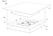
- FIG. 1 is a view illustrating an example of a conventional vibrating stimulus pad.
- the conventional vibrating stimulus pad 10 includes a pad 11, a control unit 12, a power supply 13, a vibration generator 14, a magnetic force generator 15, a cover 16, a release paper 17, and a nonwoven fabric 18.
- the control unit 12, the power supply 13, and the vibration generator 14 are installed on one surface of the pad 11 while they are connected to each other, and the magnetic force generator 15 made of a magnet and a far infrared ray generating material 19 of grains are attached on the surface.
- the cover 16 is attached to the pad 11 to cover the control unit 12, the power supply 13, and the vibration generator 14, and the release paper 17 is attached on the other surface of the pad 11.
- the nonwoven fabric 18 is attached to a surface of the pad 11 to cover the whole surface of the pad 11.
- the conventional vibrating stimulus pad has the same appearance and the same attaching function onto an affected part as those of a conventional pad without a vibration function, and thus has the same drawbacks as that of the conventional pad, i.e. difficulty to be attached to a human joint.
- the conventional vibrating stimulus pad has an attaching force onto a human affected part completely depending on the adhesive force of the adhesive layer.
- a human joint has not only more than one parts through which the joint is bending ("a bending part") but also the bending part(s) frequently moves along with the human body activities.
- a part of the conventional vibrating stimulus pad gets to be separated from the affected part around the bending part of the joint.
- the separated part of the conventional vibrating stimulus pad gets gradually dry due to the exposure of the adhesive layer to the air and the adhesive force is deteriorated as time goes by, thereby resulting in detachment of the pad from the affected part.
- an improved vibrating stimulus pad has been required to be developed that it can be well attached to an affected part, such as a joint to which the pad is generally difficult to be attached.
- the conventional vibrating stimulus pad provides no other function than permeating medicine into an affected part by vibration, its functions have been very limited.
- an object of the present invention is to provide a vibrating stimulus pad easily attached to a affected part to which the pad is difficult to be attached.
- the present also provides a vibrating stimulus pad to be able to carrying out physical therapy through vibrating stimulus by applying vibration to an affected part of the body and simultaneously to maximize permeation of medicine into the affected part.
- the present invention further provides a vibrating stimulus pad for soothing the affected part and for mitigating a pain by applying warmth or low frequency stimulus to the affected part.
- a vibrating stimulus pad comprising a flexible body; a drug layer attached to a lower surface of the body and comprising adhesive in which anti-inflammatory and/or analgesic drugs are contained; a vibration module attached to an upper surface of the body and comprising a vibration motor and a battery; and a plurality of adhesive legs installed along the circumference of the body.
- Each of the adhesive legs comprises an adhesive sucker and a flexible connector extending from the body to connect the sucker to the body, wherein the connectors have an arc-shape bent toward the upper surface of the body to transmit an elastic force to the body to be able to be tightly attached to an affected part.
- the plurality of adhesive legs further comprises low frequency electrodes.
- the vibrating stimulus pad further comprises an exothermic layer in which an exothermic wire is installed on the upper surface of the body.
- the exothermic layer and the vibration module are sequentially installed on the upper surface of the body.
- the vibrating stimulus pad may be well attached to an affected part of a patient, to which the pad is difficult to be attached, through a flexible body and a plurality of adhesive legs along the circumference of the body. That is, the plurality of legs is attached to a bending part around a joint and restricts the separation of the vibrating stimulus pad from the affected part to the most as possible.
- vibrations are applied to the affected part of human body by the vibration module attached to the body of the pad so that physical therapy is carried out by the vibrating stimulus and simultaneously permeation of medicine contained in the drug layer which is attached to the part facing the affected part of the human body can be maximized.
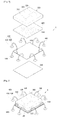
- FIG. 2 is an exploded perspective view illustrating a vibrating stimulus pad according to an embodiment of the present invention.
- FIG. 3 is a perspective view illustrating an assembly of the vibrating stimulus pad in FIG. 2 .
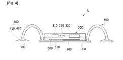
- FIG. 4 is a sectional view of FIG. 3 .
- a vibrating stimulus pad A comprises a flexible body 100, a drug layer 200 attached to a lower surface of the body 100, that is, to a portion facing a patient's affected part and comprising adhesive in which anti-inflammatory and/or analgesic drugs are contained, and a vibration module 300 attached to an upper surface of the body 100 and having a vibration motor 310 and a battery 320.
- the body 100 is made of a flexible plastic, silicon, and the like and has a rectangular shape.
- a plurality of legs 400 with adhesive forces extends along the circumference of the body 100.
- the number of legs 400 is preferably six to eight and is equally spaced from each other along the circumference of the body 100. However, it is noted that the number of the legs 400 may be increased or decreased as necessary.
- Each of the legs 400 comprises a sucker 410 with an adhesive force and a flexible connector 420 extending from the body 100 to connect the body 100 to the sucker 410.
- the connector 420 has an arc-shape bending toward the body 100 so that the connectors 420 apply elastic forces to the body such that the body 100 is attached tightly to a patient's affected part of the body, while the connectors 420 are fixed to the affected part by the suckers 410.
- the legs 400 extend from the body 100 and are made of the same material as that of the body 100. However, in the case where the connector 420 is made of a flexible material and a fixing force of the body 100 is not strong enough, the legs 400 may be made of other material having higher elastic forces than that of the body 100.
- the vibrating stimulus pad 100 may be easily attached to a patient's affected part such as a joint to which a pad is difficult to be attached.
- the plurality of legs 400 is attached to parts bent along a joint, and restricts the vibrating stimulus pad A from being separated from the patient's affected part to the most as possible.
- the plurality of legs 400 further comprises low frequency electrodes 500 which are preferably provided in the suckers 410.
- the low frequency electrodes 500 are powered through the battery 320 of the vibration module 300.
- the body 100 or the vibration module 200 further comprises vibrators (not shown) which generate a low frequency current with the electric power applied from the battery 320 and provide the generated low frequency current to the low frequency electrodes 500.
- vibrators not shown
- the body 100 further comprises an exothermic layer 600 in which an exothermic wire 610 is equipped, while the exothermic layer 600 is powered from the battery 320 of the vibration module 300.
- the vibrating stimulus pad A further comprises a power switch 330 electrically connected to the battery 320 to control the power supply, wherein the electric power is supplied to the vibration module 300, the low frequency electrodes 500, and the exothermic layer 600 when the power switch 330 is switched "ON.”
- the exothermic layer 600 and the vibration module 300 are sequentially installed on the upper surface of the body 100.
- the vibrating stimulus pad A of the present invention carries out physical therapy using vibrating stimulus by applying vibration to a patient's affected part by the vibration module 300 which is attached to the body 100 and maximizes permeation of medicine contained in the drug layer 200 that is attached to a portion of the body 100 which will face the patient' affected part.
- the vibration module 300, the exothermic layer 600, the low frequency electrodes 500, and the drug layer 200 containing various western and/or oriental medicines enable physical therapy and drug treatment at the same time.
- the thickness of the vibrating stimulus pad A in FIGS. 2 to 4 is illustrated with exaggeration for understanding and explaining the internal structure of the pad according to the present invention, and it is noted herewith that the actual product is manufactured to be thinner than that shown in the drawings.
Landscapes
- Health & Medical Sciences (AREA)
- Public Health (AREA)
- Veterinary Medicine (AREA)
- Life Sciences & Earth Sciences (AREA)
- Animal Behavior & Ethology (AREA)
- General Health & Medical Sciences (AREA)
- Engineering & Computer Science (AREA)
- Biomedical Technology (AREA)
- Thermal Sciences (AREA)
- Heart & Thoracic Surgery (AREA)
- Epidemiology (AREA)
- Physics & Mathematics (AREA)
- Vascular Medicine (AREA)
- Physical Education & Sports Medicine (AREA)
- Pain & Pain Management (AREA)
- Rehabilitation Therapy (AREA)
- Nuclear Medicine, Radiotherapy & Molecular Imaging (AREA)
- Radiology & Medical Imaging (AREA)
- Emergency Medicine (AREA)
- Bioinformatics & Cheminformatics (AREA)
- Chemical & Material Sciences (AREA)
- Medicinal Chemistry (AREA)
- Pharmacology & Pharmacy (AREA)
- Percussion Or Vibration Massage (AREA)
- Electrotherapy Devices (AREA)
- Dermatology (AREA)
- Media Introduction/Drainage Providing Device (AREA)
Abstract
Description
- The present invention relates to a vibrating stimulus pad, and particularly to a vibrating stimulus pad being capable to be easily attached to an affected part of a body, such as a joint, to which the pad is generally difficult to be well attached.
- In general, various types of cataplasmas (including various patches and puffs) are known as pads attached to affected parts of a patient and comprise anti-inflammatory and/or analgesic drugs. The cataplasmas may be provided by coating one surface of a backing layer having an approximately rectangular shape with adhesives comprising medicine and by attaching a release paper (a protection layer) to the adhesive.
- The cataplasma is used in a manner that when the whole pad is attached to an affected part using the adhesive force of the adhesive, after separation of the release paper attached to the adhesive, the medicine contained in the adhesive permeates into the skin of a patient.
- However, different from oral administration, injection or direct application of a medicine, since the medicine contained in the adhesive of the cataplasma is absorbed through the skin, it was not easy for a medicine to be absorbed and/or to be permeated deep enough through the patient's skin.
- Moreover, since the conventional cataplasmas are mainly manufactured to mitigate arthralgia or myalgia and are directly attached to an affected part, they do not suit the purposes to treat internal symptoms or pains, and their functions and uses have to be maintained simple.
- For these reasons, technical efforts to increase permeation of medicine into an affected part have been carried out and an invention of improved permeation of medicine by generating vibration is disclosed herein as part of these technical efforts.
-
FIG. 1 is a view illustrating an example of a conventional vibrating stimulus pad. As illustrated, the conventionalvibrating stimulus pad 10 includes apad 11, acontrol unit 12, apower supply 13, avibration generator 14, amagnetic force generator 15, acover 16, arelease paper 17, and anonwoven fabric 18. Thecontrol unit 12, thepower supply 13, and thevibration generator 14 are installed on one surface of thepad 11 while they are connected to each other, and themagnetic force generator 15 made of a magnet and a far infraredray generating material 19 of grains are attached on the surface. Thecover 16 is attached to thepad 11 to cover thecontrol unit 12, thepower supply 13, and thevibration generator 14, and therelease paper 17 is attached on the other surface of thepad 11. Finally, thenonwoven fabric 18 is attached to a surface of thepad 11 to cover the whole surface of thepad 11. - However, the conventional vibrating stimulus pad has the same appearance and the same attaching function onto an affected part as those of a conventional pad without a vibration function, and thus has the same drawbacks as that of the conventional pad, i.e. difficulty to be attached to a human joint.
- That is, the conventional vibrating stimulus pad has an attaching force onto a human affected part completely depending on the adhesive force of the adhesive layer. But a human joint has not only more than one parts through which the joint is bending ("a bending part") but also the bending part(s) frequently moves along with the human body activities. Thus, a part of the conventional vibrating stimulus pad gets to be separated from the affected part around the bending part of the joint. Then, the separated part of the conventional vibrating stimulus pad gets gradually dry due to the exposure of the adhesive layer to the air and the adhesive force is deteriorated as time goes by, thereby resulting in detachment of the pad from the affected part.
- Therefore, an improved vibrating stimulus pad has been required to be developed that it can be well attached to an affected part, such as a joint to which the pad is generally difficult to be attached.
- Moreover, since the conventional vibrating stimulus pad provides no other function than permeating medicine into an affected part by vibration, its functions have been very limited.
- Accordingly, the present invention has been made to solve the above-mentioned problems presented in the prior art, and an object of the present invention is to provide a vibrating stimulus pad easily attached to a affected part to which the pad is difficult to be attached.
- The present also provides a vibrating stimulus pad to be able to carrying out physical therapy through vibrating stimulus by applying vibration to an affected part of the body and simultaneously to maximize permeation of medicine into the affected part.
- The present invention further provides a vibrating stimulus pad for soothing the affected part and for mitigating a pain by applying warmth or low frequency stimulus to the affected part.
- In order to solve the problems described above, there is provided a vibrating stimulus pad comprising a flexible body; a drug layer attached to a lower surface of the body and comprising adhesive in which anti-inflammatory and/or analgesic drugs are contained; a vibration module attached to an upper surface of the body and comprising a vibration motor and a battery; and a plurality of adhesive legs installed along the circumference of the body.
- Each of the adhesive legs comprises an adhesive sucker and a flexible connector extending from the body to connect the sucker to the body, wherein the connectors have an arc-shape bent toward the upper surface of the body to transmit an elastic force to the body to be able to be tightly attached to an affected part.
- Moreover, the plurality of adhesive legs further comprises low frequency electrodes.
- The vibrating stimulus pad further comprises an exothermic layer in which an exothermic wire is installed on the upper surface of the body.
- Moreover, the exothermic layer and the vibration module are sequentially installed on the upper surface of the body.
- According to the present invention, the vibrating stimulus pad may be well attached to an affected part of a patient, to which the pad is difficult to be attached, through a flexible body and a plurality of adhesive legs along the circumference of the body. That is, the plurality of legs is attached to a bending part around a joint and restricts the separation of the vibrating stimulus pad from the affected part to the most as possible.
- Furthermore, vibrations are applied to the affected part of human body by the vibration module attached to the body of the pad so that physical therapy is carried out by the vibrating stimulus and simultaneously permeation of medicine contained in the drug layer which is attached to the part facing the affected part of the human body can be maximized.
- By applying warmth through the exothermic layer or low frequency stimulus through low frequency electrodes attached to the plurality legs to the affected part, it may be soothed and a pain may be mitigated. Hence physical therapy and drug treatment can be carried out simultaneously due to a vibration module, an exothermic layer, the low frequency electrodes, and drug layer containing various western medicines and/or oriental medicines.
-
-
FIG. 1 is a view illustrating a conventional vibrating stimulus pad. -
FIG. 2 is an exploded perspective view illustrating a vibrating stimulus pad according to an embodiment of the present invention. -
FIG. 3 is a perspective view illustrating an assembly of the vibrating stimulus pad inFIG. 2 . -
FIG. 4 is a sectional view ofFIG. 3 . - Hereinafter, embodiments of the present invention will be described in detail with reference to the accompanying drawings.
-
FIG. 2 is an exploded perspective view illustrating a vibrating stimulus pad according to an embodiment of the present invention.FIG. 3 is a perspective view illustrating an assembly of the vibrating stimulus pad inFIG. 2 .FIG. 4 is a sectional view ofFIG. 3 . - As illustrated in
FIGS. 2 to 4 , a vibrating stimulus pad A according to an embodiment of the present invention comprises aflexible body 100, adrug layer 200 attached to a lower surface of thebody 100, that is, to a portion facing a patient's affected part and comprising adhesive in which anti-inflammatory and/or analgesic drugs are contained, and avibration module 300 attached to an upper surface of thebody 100 and having avibration motor 310 and abattery 320. - First, the
body 100 is made of a flexible plastic, silicon, and the like and has a rectangular shape. - Moreover, a plurality of
legs 400 with adhesive forces extends along the circumference of thebody 100. - In this case, the number of
legs 400 is preferably six to eight and is equally spaced from each other along the circumference of thebody 100. However, it is noted that the number of thelegs 400 may be increased or decreased as necessary. - Each of the
legs 400 comprises asucker 410 with an adhesive force and aflexible connector 420 extending from thebody 100 to connect thebody 100 to thesucker 410. Theconnector 420 has an arc-shape bending toward thebody 100 so that theconnectors 420 apply elastic forces to the body such that thebody 100 is attached tightly to a patient's affected part of the body, while theconnectors 420 are fixed to the affected part by thesuckers 410. - The
legs 400 extend from thebody 100 and are made of the same material as that of thebody 100. However, in the case where theconnector 420 is made of a flexible material and a fixing force of thebody 100 is not strong enough, thelegs 400 may be made of other material having higher elastic forces than that of thebody 100. - Thus, due to the
body 100 made of a flexible material and the plurality oflegs 400 attached to the circumference of thebody 100 and added with adhesive forces, the vibratingstimulus pad 100 may be easily attached to a patient's affected part such as a joint to which a pad is difficult to be attached. - That is, the plurality of
legs 400 is attached to parts bent along a joint, and restricts the vibrating stimulus pad A from being separated from the patient's affected part to the most as possible. - The plurality of
legs 400 further compriseslow frequency electrodes 500 which are preferably provided in thesuckers 410. Thelow frequency electrodes 500 are powered through thebattery 320 of thevibration module 300. - Moreover, preferably the
body 100 or thevibration module 200 further comprises vibrators (not shown) which generate a low frequency current with the electric power applied from thebattery 320 and provide the generated low frequency current to thelow frequency electrodes 500. - The
body 100 further comprises anexothermic layer 600 in which anexothermic wire 610 is equipped, while theexothermic layer 600 is powered from thebattery 320 of thevibration module 300. - The vibrating stimulus pad A further comprises a
power switch 330 electrically connected to thebattery 320 to control the power supply, wherein the electric power is supplied to thevibration module 300, thelow frequency electrodes 500, and theexothermic layer 600 when thepower switch 330 is switched "ON." - The
exothermic layer 600 and thevibration module 300 are sequentially installed on the upper surface of thebody 100. - As seen from the embodiments of
FIGS. 2 to 4 , the vibrating stimulus pad A of the present invention carries out physical therapy using vibrating stimulus by applying vibration to a patient's affected part by thevibration module 300 which is attached to thebody 100 and maximizes permeation of medicine contained in thedrug layer 200 that is attached to a portion of thebody 100 which will face the patient' affected part. - Moreover, warmth or the low frequency stimulus is applied to the patient's affected part through the
exothermic layer 600 and thelow frequency electrodes 500 attached to the plurality oflegs 400, so that the patient's affected part can be soothed and pain can be mitigated. Thus, thevibration module 300, theexothermic layer 600, thelow frequency electrodes 500, and thedrug layer 200 containing various western and/or oriental medicines enable physical therapy and drug treatment at the same time. - The thickness of the vibrating stimulus pad A in
FIGS. 2 to 4 is illustrated with exaggeration for understanding and explaining the internal structure of the pad according to the present invention, and it is noted herewith that the actual product is manufactured to be thinner than that shown in the drawings. - Although a preferred embodiment of the present invention has been described for illustrative purposes, those skilled in the art will appreciate that various modifications, additions and substitutions are possible, without departing from the scope and spirit of the invention as disclosed in the accompanying claims.
-
- A: vibrating stimulus pad 100: body
- 200: drug layer 300: vibration module
- 400: leg 500: low frequency electrode
- 600: exothermic layer
Claims (5)
- A vibrating stimulus pad comprising:a flexible body;a drug layer attached to a lower surface of the body and made of adhesive in which anti-inflammatory and/or analgesic drugs are contained;a vibration module attached to an upper surface of the body and including a vibration motor and a battery; anda plurality of adhesive legs installed along the circumference of the body.
- The vibrating stimulus pad of claim 1, wherein each of the adhesive legs comprises an adhesive sucker a flexible connector extending from the body to connect the sucker to the body,
wherein the connectors have an arc-shape bent toward the upper surface of the body to transmit an elastic force to the body to be closely attached to a patient's affected part. - The vibrating stimulus pad of claim 1, wherein the plurality of adhesive legs further comprises low frequency electrodes.
- The vibrating stimulus pad of claim 1, further comprising an exothermic layer in which an exothermic wire is installed in the upper surface of the body.
- The vibrating stimulus pad of claim 4, wherein the exothermic layer and the vibration module are sequentially installed on the upper surface of the body.
Applications Claiming Priority (2)
| Application Number | Priority Date | Filing Date | Title |
|---|---|---|---|
| KR2020110010216U KR200464913Y1 (en) | 2011-11-17 | 2011-11-17 | Vibration stimulus pad |
| PCT/KR2012/009533 WO2013073808A1 (en) | 2011-11-17 | 2012-11-13 | Vibrating stimulus pad |
Publications (3)
| Publication Number | Publication Date |
|---|---|
| EP2764858A1 true EP2764858A1 (en) | 2014-08-13 |
| EP2764858A4 EP2764858A4 (en) | 2015-05-27 |
| EP2764858B1 EP2764858B1 (en) | 2018-09-12 |
Family
ID=48429828
Family Applications (1)
| Application Number | Title | Priority Date | Filing Date |
|---|---|---|---|
| EP12850118.6A Not-in-force EP2764858B1 (en) | 2011-11-17 | 2012-11-13 | Vibrating stimulus pad |
Country Status (9)
| Country | Link |
|---|---|
| US (1) | US10034815B2 (en) |
| EP (1) | EP2764858B1 (en) |
| JP (1) | JP5878984B2 (en) |
| KR (1) | KR200464913Y1 (en) |
| CN (1) | CN203898684U (en) |
| MY (1) | MY176688A (en) |
| SG (1) | SG11201402384TA (en) |
| TW (1) | TWM455522U (en) |
| WO (1) | WO2013073808A1 (en) |
Families Citing this family (4)
| Publication number | Priority date | Publication date | Assignee | Title |
|---|---|---|---|---|
| CN107158555A (en) * | 2017-06-26 | 2017-09-15 | 苏州科技城医院 | External application pain of alleviation apparatus and system |
| US10524978B2 (en) * | 2017-07-14 | 2020-01-07 | Hyper Ice, Inc. | Vibration and heat generation apparatus for use with compression wrap |
| US10695262B2 (en) | 2017-12-05 | 2020-06-30 | Brownmed, Inc. | Flexible vibration module for snap in attachment to a grommet embedded in a compression wrap |
| WO2021168369A1 (en) * | 2020-02-21 | 2021-08-26 | Omega Dolor Inc. | Systems and methods for pain management |
Family Cites Families (17)
| Publication number | Priority date | Publication date | Assignee | Title |
|---|---|---|---|---|
| JPH06296704A (en) * | 1993-04-14 | 1994-10-25 | Panpukin House:Kk | Low frequency therapeutic device for sole of foot |
| NZ507874A (en) * | 1996-05-10 | 2003-01-31 | Wallace J | Dressing with one or more elastic sections and adhesive on one side |
| KR200167444Y1 (en) | 1999-08-09 | 2000-02-15 | 김지인 | Medical pad |
| KR200219490Y1 (en) | 2000-10-31 | 2001-04-02 | 이양희 | A massage for vibration of skin |
| JP2003204982A (en) * | 2002-01-09 | 2003-07-22 | Byeong Gon Kim | Abdomen warming and vibrating belt |
| US9084879B2 (en) * | 2002-01-22 | 2015-07-21 | Encore Medical Asset Corporation | Method and device for the iontophoretic delivery of a drug |
| US7300409B2 (en) * | 2005-05-12 | 2007-11-27 | S.C. Johnson & Son, Inc. | Therapy patch |
| US20060276741A1 (en) * | 2005-06-06 | 2006-12-07 | Henley Julian L | Device and method for delivery of therapeutic agents to the dermis and epidermis |
| US20070260171A1 (en) * | 2005-09-27 | 2007-11-08 | Higuchi John W | Intraocular iontophoretic device and associated methods |
| KR20070079760A (en) * | 2006-02-03 | 2007-08-08 | 주식회사메디펄스 | Low frequency poultice |
| WO2009044400A2 (en) * | 2007-10-01 | 2009-04-09 | Kineticure Limited | Wearable vibrating means and thermal conditioning therapeutic devices |
| WO2009085739A1 (en) * | 2007-12-27 | 2009-07-09 | Tti Ellebeau, Inc. | Iontophoresis device having an active electrode unit |
| US20090299266A1 (en) * | 2008-06-02 | 2009-12-03 | Mattioli Engineering Ltd. | Method and apparatus for skin absorption enhancement and transdermal drug delivery |
| CA2752229C (en) * | 2009-02-12 | 2018-11-20 | Perfuzia Medical, Inc. | Devices and methods for manipulating circulation in the circulatory system of a patient |
| US8348922B2 (en) * | 2009-02-12 | 2013-01-08 | Incube Labs, Llc | Method and apparatus for oscillatory iontophoretic transdermal delivery of a therapeutic agent |
| KR20110011789A (en) * | 2009-07-29 | 2011-02-09 | 김규정 | Vibration wave |
| US9327105B2 (en) * | 2010-03-26 | 2016-05-03 | Itrace Biomedical Inc. | Active transdermal drug delivery system and the method thereof |
-
2011
- 2011-11-17 KR KR2020110010216U patent/KR200464913Y1/en not_active Expired - Fee Related
-
2012
- 2012-11-13 EP EP12850118.6A patent/EP2764858B1/en not_active Not-in-force
- 2012-11-13 SG SG11201402384TA patent/SG11201402384TA/en unknown
- 2012-11-13 MY MYPI2014701197A patent/MY176688A/en unknown
- 2012-11-13 CN CN201290000982.9U patent/CN203898684U/en not_active Expired - Fee Related
- 2012-11-13 US US14/358,035 patent/US10034815B2/en not_active Expired - Fee Related
- 2012-11-13 JP JP2014542231A patent/JP5878984B2/en not_active Expired - Fee Related
- 2012-11-13 WO PCT/KR2012/009533 patent/WO2013073808A1/en not_active Ceased
- 2012-11-16 TW TW101222266U patent/TWM455522U/en not_active IP Right Cessation
Also Published As
| Publication number | Publication date |
|---|---|
| SG11201402384TA (en) | 2014-09-26 |
| EP2764858B1 (en) | 2018-09-12 |
| JP2015515285A (en) | 2015-05-28 |
| MY176688A (en) | 2020-08-19 |
| EP2764858A4 (en) | 2015-05-27 |
| US10034815B2 (en) | 2018-07-31 |
| US20140309563A1 (en) | 2014-10-16 |
| KR200464913Y1 (en) | 2013-01-31 |
| CN203898684U (en) | 2014-10-29 |
| TWM455522U (en) | 2013-06-21 |
| JP5878984B2 (en) | 2016-03-08 |
| WO2013073808A1 (en) | 2013-05-23 |
Similar Documents
| Publication | Publication Date | Title |
|---|---|---|
| US10071198B2 (en) | Adhesive structure for medical device | |
| US20190105487A1 (en) | Wound healing electrode set | |
| JPH08505303A (en) | Iontophoretic drug administration device with flexible means | |
| KR20120032489A (en) | Assembly arrangement for a bandage holding a transcutaneous electrical nerve stimulation device | |
| EP2764858B1 (en) | Vibrating stimulus pad | |
| WO2004073647A2 (en) | Ultrasonically enhanced saline treatment for burn damaged skin | |
| CN104436451B (en) | A kind of human body patch of mating therapeutic equipment | |
| JP2011502659A (en) | Ultrasonic drug paste | |
| TW201138885A (en) | Iontophoretic patch | |
| CN100400124C (en) | medical plaster | |
| US20230010696A1 (en) | Absorption enhancing wearable device | |
| JP2014200384A (en) | Electrostimulator for neck | |
| KR200403033Y1 (en) | Portable skin care device for beauty pack | |
| WO2019146714A1 (en) | Weak current sheet | |
| CN103764090A (en) | Vibration module for skin massage | |
| KR101333433B1 (en) | Pain Relief Patch with TENS | |
| US20130345782A1 (en) | Electrode for subcutaneous electolipolysis | |
| JP2000070385A (en) | Magnetic therapeutic instrument | |
| JP7128520B2 (en) | Weak current sheet | |
| HK1197141A2 (en) | Vibrating stimulus pad | |
| JP3156656U (en) | Vibration massage ship or affixed sheet and its product structure | |
| US7979118B2 (en) | Low frequency generation poultice | |
| CN121819158A (en) | A cervical vagus nerve stimulation device and its preparation method | |
| CN121819164A (en) | A cervical vagus nerve stimulation device and its preparation method | |
| TWM481026U (en) | Electrotherapy device for assisting muscle contraction |
Legal Events
| Date | Code | Title | Description |
|---|---|---|---|
| PUAI | Public reference made under article 153(3) epc to a published international application that has entered the european phase |
Free format text: ORIGINAL CODE: 0009012 |
|
| 17P | Request for examination filed |
Effective date: 20140508 |
|
| AK | Designated contracting states |
Kind code of ref document: A1 Designated state(s): AL AT BE BG CH CY CZ DE DK EE ES FI FR GB GR HR HU IE IS IT LI LT LU LV MC MK MT NL NO PL PT RO RS SE SI SK SM TR |
|
| DAX | Request for extension of the european patent (deleted) | ||
| RA4 | Supplementary search report drawn up and despatched (corrected) |
Effective date: 20150424 |
|
| RIC1 | Information provided on ipc code assigned before grant |
Ipc: A61N 1/32 20060101ALI20150420BHEP Ipc: A61K 9/70 20060101ALI20150420BHEP Ipc: A61F 7/02 20060101ALI20150420BHEP Ipc: A61H 23/02 20060101AFI20150420BHEP |
|
| GRAP | Despatch of communication of intention to grant a patent |
Free format text: ORIGINAL CODE: EPIDOSNIGR1 |
|
| STAA | Information on the status of an ep patent application or granted ep patent |
Free format text: STATUS: GRANT OF PATENT IS INTENDED |
|
| INTG | Intention to grant announced |
Effective date: 20180424 |
|
| GRAS | Grant fee paid |
Free format text: ORIGINAL CODE: EPIDOSNIGR3 |
|
| GRAA | (expected) grant |
Free format text: ORIGINAL CODE: 0009210 |
|
| STAA | Information on the status of an ep patent application or granted ep patent |
Free format text: STATUS: THE PATENT HAS BEEN GRANTED |
|
| AK | Designated contracting states |
Kind code of ref document: B1 Designated state(s): AL AT BE BG CH CY CZ DE DK EE ES FI FR GB GR HR HU IE IS IT LI LT LU LV MC MK MT NL NO PL PT RO RS SE SI SK SM TR |
|
| REG | Reference to a national code |
Ref country code: GB Ref legal event code: FG4D |
|
| REG | Reference to a national code |
Ref country code: CH Ref legal event code: EP |
|
| REG | Reference to a national code |
Ref country code: IE Ref legal event code: FG4D |
|
| REG | Reference to a national code |
Ref country code: DE Ref legal event code: R096 Ref document number: 602012051110 Country of ref document: DE |
|
| REG | Reference to a national code |
Ref country code: AT Ref legal event code: REF Ref document number: 1039706 Country of ref document: AT Kind code of ref document: T Effective date: 20181015 |
|
| REG | Reference to a national code |
Ref country code: NL Ref legal event code: MP Effective date: 20180912 |
|
| REG | Reference to a national code |
Ref country code: LT Ref legal event code: MG4D |
|
| PG25 | Lapsed in a contracting state [announced via postgrant information from national office to epo] |
Ref country code: LT Free format text: LAPSE BECAUSE OF FAILURE TO SUBMIT A TRANSLATION OF THE DESCRIPTION OR TO PAY THE FEE WITHIN THE PRESCRIBED TIME-LIMIT Effective date: 20180912 Ref country code: FI Free format text: LAPSE BECAUSE OF FAILURE TO SUBMIT A TRANSLATION OF THE DESCRIPTION OR TO PAY THE FEE WITHIN THE PRESCRIBED TIME-LIMIT Effective date: 20180912 Ref country code: GR Free format text: LAPSE BECAUSE OF FAILURE TO SUBMIT A TRANSLATION OF THE DESCRIPTION OR TO PAY THE FEE WITHIN THE PRESCRIBED TIME-LIMIT Effective date: 20181213 Ref country code: RS Free format text: LAPSE BECAUSE OF FAILURE TO SUBMIT A TRANSLATION OF THE DESCRIPTION OR TO PAY THE FEE WITHIN THE PRESCRIBED TIME-LIMIT Effective date: 20180912 Ref country code: NO Free format text: LAPSE BECAUSE OF FAILURE TO SUBMIT A TRANSLATION OF THE DESCRIPTION OR TO PAY THE FEE WITHIN THE PRESCRIBED TIME-LIMIT Effective date: 20181212 Ref country code: SE Free format text: LAPSE BECAUSE OF FAILURE TO SUBMIT A TRANSLATION OF THE DESCRIPTION OR TO PAY THE FEE WITHIN THE PRESCRIBED TIME-LIMIT Effective date: 20180912 Ref country code: BG Free format text: LAPSE BECAUSE OF FAILURE TO SUBMIT A TRANSLATION OF THE DESCRIPTION OR TO PAY THE FEE WITHIN THE PRESCRIBED TIME-LIMIT Effective date: 20181212 |
|
| PG25 | Lapsed in a contracting state [announced via postgrant information from national office to epo] |
Ref country code: HR Free format text: LAPSE BECAUSE OF FAILURE TO SUBMIT A TRANSLATION OF THE DESCRIPTION OR TO PAY THE FEE WITHIN THE PRESCRIBED TIME-LIMIT Effective date: 20180912 Ref country code: LV Free format text: LAPSE BECAUSE OF FAILURE TO SUBMIT A TRANSLATION OF THE DESCRIPTION OR TO PAY THE FEE WITHIN THE PRESCRIBED TIME-LIMIT Effective date: 20180912 Ref country code: AL Free format text: LAPSE BECAUSE OF FAILURE TO SUBMIT A TRANSLATION OF THE DESCRIPTION OR TO PAY THE FEE WITHIN THE PRESCRIBED TIME-LIMIT Effective date: 20180912 |
|
| REG | Reference to a national code |
Ref country code: AT Ref legal event code: MK05 Ref document number: 1039706 Country of ref document: AT Kind code of ref document: T Effective date: 20180912 |
|
| PG25 | Lapsed in a contracting state [announced via postgrant information from national office to epo] |
Ref country code: RO Free format text: LAPSE BECAUSE OF FAILURE TO SUBMIT A TRANSLATION OF THE DESCRIPTION OR TO PAY THE FEE WITHIN THE PRESCRIBED TIME-LIMIT Effective date: 20180912 Ref country code: CZ Free format text: LAPSE BECAUSE OF FAILURE TO SUBMIT A TRANSLATION OF THE DESCRIPTION OR TO PAY THE FEE WITHIN THE PRESCRIBED TIME-LIMIT Effective date: 20180912 Ref country code: ES Free format text: LAPSE BECAUSE OF FAILURE TO SUBMIT A TRANSLATION OF THE DESCRIPTION OR TO PAY THE FEE WITHIN THE PRESCRIBED TIME-LIMIT Effective date: 20180912 Ref country code: PL Free format text: LAPSE BECAUSE OF FAILURE TO SUBMIT A TRANSLATION OF THE DESCRIPTION OR TO PAY THE FEE WITHIN THE PRESCRIBED TIME-LIMIT Effective date: 20180912 Ref country code: IS Free format text: LAPSE BECAUSE OF FAILURE TO SUBMIT A TRANSLATION OF THE DESCRIPTION OR TO PAY THE FEE WITHIN THE PRESCRIBED TIME-LIMIT Effective date: 20190112 Ref country code: NL Free format text: LAPSE BECAUSE OF FAILURE TO SUBMIT A TRANSLATION OF THE DESCRIPTION OR TO PAY THE FEE WITHIN THE PRESCRIBED TIME-LIMIT Effective date: 20180912 Ref country code: IT Free format text: LAPSE BECAUSE OF FAILURE TO SUBMIT A TRANSLATION OF THE DESCRIPTION OR TO PAY THE FEE WITHIN THE PRESCRIBED TIME-LIMIT Effective date: 20180912 Ref country code: EE Free format text: LAPSE BECAUSE OF FAILURE TO SUBMIT A TRANSLATION OF THE DESCRIPTION OR TO PAY THE FEE WITHIN THE PRESCRIBED TIME-LIMIT Effective date: 20180912 Ref country code: AT Free format text: LAPSE BECAUSE OF FAILURE TO SUBMIT A TRANSLATION OF THE DESCRIPTION OR TO PAY THE FEE WITHIN THE PRESCRIBED TIME-LIMIT Effective date: 20180912 |
|
| PG25 | Lapsed in a contracting state [announced via postgrant information from national office to epo] |
Ref country code: SM Free format text: LAPSE BECAUSE OF FAILURE TO SUBMIT A TRANSLATION OF THE DESCRIPTION OR TO PAY THE FEE WITHIN THE PRESCRIBED TIME-LIMIT Effective date: 20180912 Ref country code: SK Free format text: LAPSE BECAUSE OF FAILURE TO SUBMIT A TRANSLATION OF THE DESCRIPTION OR TO PAY THE FEE WITHIN THE PRESCRIBED TIME-LIMIT Effective date: 20180912 Ref country code: PT Free format text: LAPSE BECAUSE OF FAILURE TO SUBMIT A TRANSLATION OF THE DESCRIPTION OR TO PAY THE FEE WITHIN THE PRESCRIBED TIME-LIMIT Effective date: 20190112 |
|
| REG | Reference to a national code |
Ref country code: DE Ref legal event code: R119 Ref document number: 602012051110 Country of ref document: DE |
|
| REG | Reference to a national code |
Ref country code: CH Ref legal event code: PL |
|
| PLBE | No opposition filed within time limit |
Free format text: ORIGINAL CODE: 0009261 |
|
| STAA | Information on the status of an ep patent application or granted ep patent |
Free format text: STATUS: NO OPPOSITION FILED WITHIN TIME LIMIT |
|
| PG25 | Lapsed in a contracting state [announced via postgrant information from national office to epo] |
Ref country code: LU Free format text: LAPSE BECAUSE OF NON-PAYMENT OF DUE FEES Effective date: 20181113 Ref country code: DK Free format text: LAPSE BECAUSE OF FAILURE TO SUBMIT A TRANSLATION OF THE DESCRIPTION OR TO PAY THE FEE WITHIN THE PRESCRIBED TIME-LIMIT Effective date: 20180912 Ref country code: MC Free format text: LAPSE BECAUSE OF FAILURE TO SUBMIT A TRANSLATION OF THE DESCRIPTION OR TO PAY THE FEE WITHIN THE PRESCRIBED TIME-LIMIT Effective date: 20180912 |
|
| REG | Reference to a national code |
Ref country code: BE Ref legal event code: MM Effective date: 20181130 |
|
| 26N | No opposition filed |
Effective date: 20190613 |
|
| REG | Reference to a national code |
Ref country code: IE Ref legal event code: MM4A |
|
| GBPC | Gb: european patent ceased through non-payment of renewal fee |
Effective date: 20181212 |
|
| PG25 | Lapsed in a contracting state [announced via postgrant information from national office to epo] |
Ref country code: LI Free format text: LAPSE BECAUSE OF NON-PAYMENT OF DUE FEES Effective date: 20181130 Ref country code: SI Free format text: LAPSE BECAUSE OF FAILURE TO SUBMIT A TRANSLATION OF THE DESCRIPTION OR TO PAY THE FEE WITHIN THE PRESCRIBED TIME-LIMIT Effective date: 20180912 Ref country code: CH Free format text: LAPSE BECAUSE OF NON-PAYMENT OF DUE FEES Effective date: 20181130 |
|
| PG25 | Lapsed in a contracting state [announced via postgrant information from national office to epo] |
Ref country code: IE Free format text: LAPSE BECAUSE OF NON-PAYMENT OF DUE FEES Effective date: 20181113 Ref country code: DE Free format text: LAPSE BECAUSE OF NON-PAYMENT OF DUE FEES Effective date: 20190601 |
|
| PG25 | Lapsed in a contracting state [announced via postgrant information from national office to epo] |
Ref country code: BE Free format text: LAPSE BECAUSE OF NON-PAYMENT OF DUE FEES Effective date: 20181130 |
|
| PG25 | Lapsed in a contracting state [announced via postgrant information from national office to epo] |
Ref country code: GB Free format text: LAPSE BECAUSE OF NON-PAYMENT OF DUE FEES Effective date: 20181212 |
|
| PG25 | Lapsed in a contracting state [announced via postgrant information from national office to epo] |
Ref country code: MT Free format text: LAPSE BECAUSE OF NON-PAYMENT OF DUE FEES Effective date: 20181113 |
|
| PG25 | Lapsed in a contracting state [announced via postgrant information from national office to epo] |
Ref country code: TR Free format text: LAPSE BECAUSE OF FAILURE TO SUBMIT A TRANSLATION OF THE DESCRIPTION OR TO PAY THE FEE WITHIN THE PRESCRIBED TIME-LIMIT Effective date: 20180912 |
|
| PG25 | Lapsed in a contracting state [announced via postgrant information from national office to epo] |
Ref country code: MK Free format text: LAPSE BECAUSE OF NON-PAYMENT OF DUE FEES Effective date: 20180912 Ref country code: HU Free format text: LAPSE BECAUSE OF FAILURE TO SUBMIT A TRANSLATION OF THE DESCRIPTION OR TO PAY THE FEE WITHIN THE PRESCRIBED TIME-LIMIT; INVALID AB INITIO Effective date: 20121113 Ref country code: CY Free format text: LAPSE BECAUSE OF FAILURE TO SUBMIT A TRANSLATION OF THE DESCRIPTION OR TO PAY THE FEE WITHIN THE PRESCRIBED TIME-LIMIT Effective date: 20180912 |
|
| PGFP | Annual fee paid to national office [announced via postgrant information from national office to epo] |
Ref country code: FR Payment date: 20200923 Year of fee payment: 9 |
|
| PG25 | Lapsed in a contracting state [announced via postgrant information from national office to epo] |
Ref country code: FR Free format text: LAPSE BECAUSE OF NON-PAYMENT OF DUE FEES Effective date: 20211130 |