EP2764707B1 - Instability detection and avoidance in a feedback system - Google Patents
Instability detection and avoidance in a feedback system Download PDFInfo
- Publication number
- EP2764707B1 EP2764707B1 EP12770397.3A EP12770397A EP2764707B1 EP 2764707 B1 EP2764707 B1 EP 2764707B1 EP 12770397 A EP12770397 A EP 12770397A EP 2764707 B1 EP2764707 B1 EP 2764707B1
- Authority
- EP
- European Patent Office
- Prior art keywords
- feedback
- signal
- sensor
- instability
- driver
- Prior art date
- Legal status (The legal status is an assumption and is not a legal conclusion. Google has not performed a legal analysis and makes no representation as to the accuracy of the status listed.)
- Active
Links
Images






Classifications
-
- H—ELECTRICITY
- H04—ELECTRIC COMMUNICATION TECHNIQUE
- H04R—LOUDSPEAKERS, MICROPHONES, GRAMOPHONE PICK-UPS OR LIKE ACOUSTIC ELECTROMECHANICAL TRANSDUCERS; ELECTRIC HEARING AIDS; PUBLIC ADDRESS SYSTEMS
- H04R1/00—Details of transducers, loudspeakers or microphones
- H04R1/10—Earpieces; Attachments therefor ; Earphones; Monophonic headphones
- H04R1/1083—Reduction of ambient noise
-
- G—PHYSICS
- G10—MUSICAL INSTRUMENTS; ACOUSTICS
- G10K—SOUND-PRODUCING DEVICES; METHODS OR DEVICES FOR PROTECTING AGAINST, OR FOR DAMPING, NOISE OR OTHER ACOUSTIC WAVES IN GENERAL; ACOUSTICS NOT OTHERWISE PROVIDED FOR
- G10K11/00—Methods or devices for transmitting, conducting or directing sound in general; Methods or devices for protecting against, or for damping, noise or other acoustic waves in general
- G10K11/16—Methods or devices for protecting against, or for damping, noise or other acoustic waves in general
- G10K11/175—Methods or devices for protecting against, or for damping, noise or other acoustic waves in general using interference effects; Masking sound
- G10K11/178—Methods or devices for protecting against, or for damping, noise or other acoustic waves in general using interference effects; Masking sound by electro-acoustically regenerating the original acoustic waves in anti-phase
- G10K11/1781—Methods or devices for protecting against, or for damping, noise or other acoustic waves in general using interference effects; Masking sound by electro-acoustically regenerating the original acoustic waves in anti-phase characterised by the analysis of input or output signals, e.g. frequency range, modes, transfer functions
- G10K11/17813—Methods or devices for protecting against, or for damping, noise or other acoustic waves in general using interference effects; Masking sound by electro-acoustically regenerating the original acoustic waves in anti-phase characterised by the analysis of input or output signals, e.g. frequency range, modes, transfer functions characterised by the analysis of the acoustic paths, e.g. estimating, calibrating or testing of transfer functions or cross-terms
- G10K11/17817—Methods or devices for protecting against, or for damping, noise or other acoustic waves in general using interference effects; Masking sound by electro-acoustically regenerating the original acoustic waves in anti-phase characterised by the analysis of input or output signals, e.g. frequency range, modes, transfer functions characterised by the analysis of the acoustic paths, e.g. estimating, calibrating or testing of transfer functions or cross-terms between the output signals and the error signals, i.e. secondary path
-
- G—PHYSICS
- G10—MUSICAL INSTRUMENTS; ACOUSTICS
- G10K—SOUND-PRODUCING DEVICES; METHODS OR DEVICES FOR PROTECTING AGAINST, OR FOR DAMPING, NOISE OR OTHER ACOUSTIC WAVES IN GENERAL; ACOUSTICS NOT OTHERWISE PROVIDED FOR
- G10K11/00—Methods or devices for transmitting, conducting or directing sound in general; Methods or devices for protecting against, or for damping, noise or other acoustic waves in general
- G10K11/16—Methods or devices for protecting against, or for damping, noise or other acoustic waves in general
- G10K11/175—Methods or devices for protecting against, or for damping, noise or other acoustic waves in general using interference effects; Masking sound
- G10K11/178—Methods or devices for protecting against, or for damping, noise or other acoustic waves in general using interference effects; Masking sound by electro-acoustically regenerating the original acoustic waves in anti-phase
- G10K11/1781—Methods or devices for protecting against, or for damping, noise or other acoustic waves in general using interference effects; Masking sound by electro-acoustically regenerating the original acoustic waves in anti-phase characterised by the analysis of input or output signals, e.g. frequency range, modes, transfer functions
- G10K11/17821—Methods or devices for protecting against, or for damping, noise or other acoustic waves in general using interference effects; Masking sound by electro-acoustically regenerating the original acoustic waves in anti-phase characterised by the analysis of input or output signals, e.g. frequency range, modes, transfer functions characterised by the analysis of the input signals only
- G10K11/17825—Error signals
-
- G—PHYSICS
- G10—MUSICAL INSTRUMENTS; ACOUSTICS
- G10K—SOUND-PRODUCING DEVICES; METHODS OR DEVICES FOR PROTECTING AGAINST, OR FOR DAMPING, NOISE OR OTHER ACOUSTIC WAVES IN GENERAL; ACOUSTICS NOT OTHERWISE PROVIDED FOR
- G10K11/00—Methods or devices for transmitting, conducting or directing sound in general; Methods or devices for protecting against, or for damping, noise or other acoustic waves in general
- G10K11/16—Methods or devices for protecting against, or for damping, noise or other acoustic waves in general
- G10K11/175—Methods or devices for protecting against, or for damping, noise or other acoustic waves in general using interference effects; Masking sound
- G10K11/178—Methods or devices for protecting against, or for damping, noise or other acoustic waves in general using interference effects; Masking sound by electro-acoustically regenerating the original acoustic waves in anti-phase
- G10K11/1783—Methods or devices for protecting against, or for damping, noise or other acoustic waves in general using interference effects; Masking sound by electro-acoustically regenerating the original acoustic waves in anti-phase handling or detecting of non-standard events or conditions, e.g. changing operating modes under specific operating conditions
- G10K11/17833—Methods or devices for protecting against, or for damping, noise or other acoustic waves in general using interference effects; Masking sound by electro-acoustically regenerating the original acoustic waves in anti-phase handling or detecting of non-standard events or conditions, e.g. changing operating modes under specific operating conditions by using a self-diagnostic function or a malfunction prevention function, e.g. detecting abnormal output levels
-
- G—PHYSICS
- G10—MUSICAL INSTRUMENTS; ACOUSTICS
- G10K—SOUND-PRODUCING DEVICES; METHODS OR DEVICES FOR PROTECTING AGAINST, OR FOR DAMPING, NOISE OR OTHER ACOUSTIC WAVES IN GENERAL; ACOUSTICS NOT OTHERWISE PROVIDED FOR
- G10K11/00—Methods or devices for transmitting, conducting or directing sound in general; Methods or devices for protecting against, or for damping, noise or other acoustic waves in general
- G10K11/16—Methods or devices for protecting against, or for damping, noise or other acoustic waves in general
- G10K11/175—Methods or devices for protecting against, or for damping, noise or other acoustic waves in general using interference effects; Masking sound
- G10K11/178—Methods or devices for protecting against, or for damping, noise or other acoustic waves in general using interference effects; Masking sound by electro-acoustically regenerating the original acoustic waves in anti-phase
- G10K11/1785—Methods, e.g. algorithms; Devices
- G10K11/17853—Methods, e.g. algorithms; Devices of the filter
-
- G—PHYSICS
- G10—MUSICAL INSTRUMENTS; ACOUSTICS
- G10K—SOUND-PRODUCING DEVICES; METHODS OR DEVICES FOR PROTECTING AGAINST, OR FOR DAMPING, NOISE OR OTHER ACOUSTIC WAVES IN GENERAL; ACOUSTICS NOT OTHERWISE PROVIDED FOR
- G10K11/00—Methods or devices for transmitting, conducting or directing sound in general; Methods or devices for protecting against, or for damping, noise or other acoustic waves in general
- G10K11/16—Methods or devices for protecting against, or for damping, noise or other acoustic waves in general
- G10K11/175—Methods or devices for protecting against, or for damping, noise or other acoustic waves in general using interference effects; Masking sound
- G10K11/178—Methods or devices for protecting against, or for damping, noise or other acoustic waves in general using interference effects; Masking sound by electro-acoustically regenerating the original acoustic waves in anti-phase
- G10K11/1787—General system configurations
- G10K11/17875—General system configurations using an error signal without a reference signal, e.g. pure feedback
-
- H—ELECTRICITY
- H04—ELECTRIC COMMUNICATION TECHNIQUE
- H04R—LOUDSPEAKERS, MICROPHONES, GRAMOPHONE PICK-UPS OR LIKE ACOUSTIC ELECTROMECHANICAL TRANSDUCERS; ELECTRIC HEARING AIDS; PUBLIC ADDRESS SYSTEMS
- H04R3/00—Circuits for transducers
- H04R3/02—Circuits for transducers for preventing acoustic reaction, i.e. acoustic oscillatory feedback
-
- G—PHYSICS
- G10—MUSICAL INSTRUMENTS; ACOUSTICS
- G10K—SOUND-PRODUCING DEVICES; METHODS OR DEVICES FOR PROTECTING AGAINST, OR FOR DAMPING, NOISE OR OTHER ACOUSTIC WAVES IN GENERAL; ACOUSTICS NOT OTHERWISE PROVIDED FOR
- G10K2210/00—Details of active noise control [ANC] covered by G10K11/178 but not provided for in any of its subgroups
- G10K2210/10—Applications
- G10K2210/108—Communication systems, e.g. where useful sound is kept and noise is cancelled
- G10K2210/1081—Earphones, e.g. for telephones, ear protectors or headsets
-
- G—PHYSICS
- G10—MUSICAL INSTRUMENTS; ACOUSTICS
- G10K—SOUND-PRODUCING DEVICES; METHODS OR DEVICES FOR PROTECTING AGAINST, OR FOR DAMPING, NOISE OR OTHER ACOUSTIC WAVES IN GENERAL; ACOUSTICS NOT OTHERWISE PROVIDED FOR
- G10K2210/00—Details of active noise control [ANC] covered by G10K11/178 but not provided for in any of its subgroups
- G10K2210/30—Means
- G10K2210/301—Computational
- G10K2210/3026—Feedback
-
- G—PHYSICS
- G10—MUSICAL INSTRUMENTS; ACOUSTICS
- G10K—SOUND-PRODUCING DEVICES; METHODS OR DEVICES FOR PROTECTING AGAINST, OR FOR DAMPING, NOISE OR OTHER ACOUSTIC WAVES IN GENERAL; ACOUSTICS NOT OTHERWISE PROVIDED FOR
- G10K2210/00—Details of active noise control [ANC] covered by G10K11/178 but not provided for in any of its subgroups
- G10K2210/30—Means
- G10K2210/301—Computational
- G10K2210/3028—Filtering, e.g. Kalman filters or special analogue or digital filters
-
- G—PHYSICS
- G10—MUSICAL INSTRUMENTS; ACOUSTICS
- G10K—SOUND-PRODUCING DEVICES; METHODS OR DEVICES FOR PROTECTING AGAINST, OR FOR DAMPING, NOISE OR OTHER ACOUSTIC WAVES IN GENERAL; ACOUSTICS NOT OTHERWISE PROVIDED FOR
- G10K2210/00—Details of active noise control [ANC] covered by G10K11/178 but not provided for in any of its subgroups
- G10K2210/50—Miscellaneous
- G10K2210/503—Diagnostics; Stability; Alarms; Failsafe
-
- H—ELECTRICITY
- H04—ELECTRIC COMMUNICATION TECHNIQUE
- H04R—LOUDSPEAKERS, MICROPHONES, GRAMOPHONE PICK-UPS OR LIKE ACOUSTIC ELECTROMECHANICAL TRANSDUCERS; ELECTRIC HEARING AIDS; PUBLIC ADDRESS SYSTEMS
- H04R2460/00—Details of hearing devices, i.e. of ear- or headphones covered by H04R1/10 or H04R5/033 but not provided for in any of their subgroups, or of hearing aids covered by H04R25/00 but not provided for in any of its subgroups
- H04R2460/01—Hearing devices using active noise cancellation
-
- H—ELECTRICITY
- H04—ELECTRIC COMMUNICATION TECHNIQUE
- H04R—LOUDSPEAKERS, MICROPHONES, GRAMOPHONE PICK-UPS OR LIKE ACOUSTIC ELECTROMECHANICAL TRANSDUCERS; ELECTRIC HEARING AIDS; PUBLIC ADDRESS SYSTEMS
- H04R2460/00—Details of hearing devices, i.e. of ear- or headphones covered by H04R1/10 or H04R5/033 but not provided for in any of their subgroups, or of hearing aids covered by H04R25/00 but not provided for in any of its subgroups
- H04R2460/15—Determination of the acoustic seal of ear moulds or ear tips of hearing devices
Definitions
- This invention relates to instability detection and avoidance in a feedback system, in particular in a feedback active noise reduction system.
- ambient acoustic noise in an environment can have a wide range of effects on human hearing.
- Some examples of ambient noise such as engine noise in the cabin of a jet airliner, can cause minor annoyance to a passenger.
- Other examples of ambient noise such as a jackhammer on a construction site can cause permanent hearing loss.
- Techniques for the reduction of ambient acoustic noise are an active area of research, providing benefits such as more pleasurable hearing experiences and avoidance of hearing losses.
- Active noise reduction systems utilize active noise reduction techniques to reduce the amount of noise that is perceived by a user.
- Active noise reduction systems are commonly implemented using feed-forward, feedback, or a combination of feed-forward and feedback approaches.
- Feedback based systems typically measure a noise sound wave, possibly combined with other sound waves, near an area where noise reduction is desired (e.g., in an acoustic cavity such as an ear cavity).
- the measured signals are used to generate an "anti-noise signal" which is a phase inverted and scaled version of the measured noise.
- the anti-noise signal is provided to a noise cancellation driver which transduces the signal into a sound wave which is presented to the user.
- the anti-noise sound wave produced by the noise cancellation driver When the anti-noise sound wave produced by the noise cancellation driver combines in the acoustic cavity with the noise sound wave, the two sound waves cancel one another due to destructive interference. The result is a reduction in the noise level perceived by the user in the area where noise reduction is desired.
- Feedback systems generally have the potential of being unstable and producing instability based distortion.
- the gain of a feedback loop is greater than 1 at a frequency where the phase of the feedback loop is 180°, oscillatory additive signals can be generated at that frequency.
- the phase margin is the margin to reach 180° phase at a frequency at which the gain is 1, of the system being zero or negative.
- At least a part of the feedback path can include an acoustic component.
- the acoustic component may be subject to variation, for example, as a result of variation in the physical characteristics of the acoustic path.
- Patent publication WO2010/131154 A1 discloses a feedback based active noise reduction system using a closed-loop feedback with an adaptive filter, a tonal component detection to detect onset components of tonal oscillation signals to be suppressed by the filter.
- Patent publication WO2010/129272 A1 discloses a feedback based active noise reduction system using a combination of feedback and feed-forward signal paths with respective filters and an instability detection of oscillation signal components in a compression controller wherein a plurality of input signals are processed, such as a feedback signal, one or plural feed-forward signals, and an audio-pass through signal.
- variation in the acoustic path may result in instability in the system due to resulting variation in the feedback loop gain or transfer function.
- the acoustic component can have an acoustic transfer function between an acoustic driver and a feedback microphone.
- One example of a situation where the acoustic transfer function varies is when a wearer of an in-ear headphone inserts the earbud of the headphone into the ear canal. During the insertion process, the compliant tip of the earbud can become blocked, for example, by being pinched or folded over itself. Such a blocked tip can alter the acoustic transfer function, thereby altering the overall loop gain and potentially causing instability in the system.
- an active noise reduction system detects actual or potential instability by detecting characteristics of the system related to potential or actual unstable behavior (e.g., oscillation) and adapts system characteristics to mitigate such instability.
- the system adapts to variation in characteristics of an acoustic component of a feedback path that has or may induce unstable behavior to improve a user's acoustic experience.
- a feedback based active noise reduction system comprises the set of features of claim 1.
- Detecting the instability condition includes processing the plurality of feedback signals to determine a characteristic of an acoustic path between the driver and the first sensor.
- the first sensor may include a microphone and the driver may include a loudspeaker.
- the feedback element may be configured to cause one or both of the gain characteristic and the phase characteristic of the feedback element to change by a predetermined amount upon providing of the control parameter.
- the feedback element may be configured to concurrently modify a transfer function of a feedback filter, a feedforward filter, and an audio input filter upon providing of the control parameter.
- the feedback element may be configured to cause the bandwidth of the feedback element to change by a predetermined amount upon providing of the control parameter.
- the feedback element may include a low-pass filter selectably applicable to the feedback element according to the control parameter.
- the ratio of the first feedback signal to the second feedback signal may represent an acoustic impedance of the acoustic path.
- the first sensor may include a pressure microphone and the second sensor may include a velocity microphone.
- the first sensor may include a pressure microphone and the second sensor may include a pressure microphone.
- the plurality of sensors may include a third sensor for producing a third feedback signal and the instability detector may be configured to determine the validity of the instability condition detected by the instability detector based on the third feedback signal.
- the feedback element may include a first signal input for accepting an input signal
- the instability detector may include a second signal input for accepting the input signal and a driver input for accepting the driver signal
- the instability detector may be configured to detect the instability condition in the feedback element including determining a characteristic of the feedback element based on the input signal and the driver signal.
- the instability condition may include the presence of an oscillation in a specified frequency range.
- the specified frequency range may be mutually exclusive from a frequency range where active noise reduction occurs.
- the instability detector may be configured to analyze the input signal and driver signal to determine whether the oscillation is present in the driver signal and that the oscillation is not present in the input signal
- a method for detecting and avoiding instability in a feedback based active noise reduction system comprises the steps of claim 15.
- the first sensor may include a microphone and the driver may include a loudspeaker.
- Providing the control parameter to the feedback element may cause one or both of the gain characteristic and the phase characteristic of the feedback element to change by a predetermined amount.
- Providing the control parameter to the feedback element may cause a concurrent modification of a transfer function of a feedback filter, a feedforward filter, and an audio input filter.
- Providing the control parameter to the feedback element may cause the bandwidth of the feedback element to change by a predetermined amount.
- Providing the control parameter to the feedback element may cause a low-pass filter to be selectably applied to the feedback element based on the provided parameter.
- the ratio of the first feedback signal to the second feedback signal may represent an acoustic impedance of the acoustic path.
- the first sensor may include a pressure microphone and the second sensor may include a velocity microphone.
- the first sensor may include a pressure microphone and the second sensor may include a pressure microphone.
- the plurality of sensors may include a third sensor for producing a third feedback signal and detecting the instability condition may include determining the validity of the instability condition based on the third feedback signal.
- the method may also include the steps of accepting, at the feedback element, an input signal, wherein detecting the instability condition further includes accepting the input signal, accepting the driver signal, and determining a characteristic of the feedback element based on the input signal and the driver signal.
- the instability condition may include the presence of an oscillation in a specified frequency range.
- the specified frequency range may be mutually exclusive from a frequency range where active noise reduction occurs.
- Detecting the instability condition may include analyzing the input signal and driver signal to determine whether the oscillation is present in the driver signal and that the oscillation is not present in the input signal.
- Embodiments may have one or more of the following advantages.
- Embodiments may require few electronic parts, resulting in a reduced cost relative to conventional systems which include general purpose digital signal processing (DSP) hardware.
- DSP digital signal processing
- Embodiments may consume very little power (e.g., micro-watts) since they do not require high speed/low noise operational amplifiers.
- Embodiments may react to disturbances more quickly than DSP based systems which require long measurement and calculation times.
- DSP based systems do not react quickly enough to prevent a loud, high pitched sound from impinging on the eardrum for an extended duration due to the close proximity of the loudspeaker driver to the eardrum in a headphone device.
- Embodiments are immune to being triggered by audio signals alone, and can reliably detect oscillation in the presence of audio signals.
- the system described herein detects actual or potential feedback loop instability due to excessive feedback loop gain in a feedback control based active noise reduction system and mitigates the instability to return the system to a stable or more stable operating state.
- the system leverages the knowledge that:
- the system Upon detection of instability in the feedback loop, the system mitigates the instability by adjusting the gain of the feedback loop.
- a system for acoustic active noise reduction 200 receives an input signal (e.g., an audio signal), x(t) and provides a modified version of the input signal, to an acoustic driver 102.
- the acoustic driver 102 transduces the modified version of the input signal into a sound wave, y (t) , in an acoustic cavity 104.
- y(t) passes through an acoustic transfer function, A 106, between the acoustic driver 102 and a feedback microphone 108.
- the result of y(t) passing through A 106 combines with a noise sound wave, N(t) , to produce ⁇ (t) .
- the feedback microphone 108 measures ⁇ (t) , transducing the sound wave into an electrical signal, e ( t ). This signal is passed along a feedback path, through a feedback factor, H 210.
- the input signal, x (t) is provided to a first transfer function block, A 1 112.
- the output of the feedback factor H 210 is then subtracted from the output of the first transfer function block 112.
- the output of A 1 112 includes only (or predominantly) the frequency components of x(t) that are within a desired active noise reduction bandwidth, with the frequencies that are outside the desired active noise reduction bandwidth attenuated.
- the result of the subtraction is provided to first forward path gain element, G 1 116.
- the input signal, x(t) is provided to a second transfer function block, A 2 114.
- the output of the first forward path gain element G 1 116 is added to the output of the second transfer function block 114.
- the output of A 2 114 includes only the frequency components of x ( t ) that are outside the desired active noise reduction bandwidth, with the frequencies that are within the desired active noise reduction bandwidth attenuated.
- the result of the addition is provided to a second forward path gain element, G 2 118.
- the output of the second forward path element G 2 118 is provided to the acoustic driver 102.
- the purpose of injecting different components of the input signal, x ( t ) into the forward path at different stages is to apply higher gain to components of the input signal which are deemed as more important.
- the system of FIG. 1 injects the frequency components of x ( t ) that are within the active noise reduction bandwidth earlier in the system than those frequency components of x (t) that are outside of the active noise reduction bandwidth. This results in the application of more gain (i.e., both G 1 116 and G 2 118) to the frequency components that are within the active noise reduction bandwidth and the application of less gain (i.e., only G 2 118) to the frequency components that are outside the active noise reduction bandwidth. Higher feedback gain results in greater noise reduction.
- x ( t ) 0 (i.e., no input signal is provided).
- the active noise reduction system reduces ambient noise at the feedback microphone, driving the signal sensed at the microphone to zero.
- e ( t ) is a measurement of the acoustic signal in the acoustic cavity at the location of the feedback microphone 108.
- the G 1 G 2 HA term in the denominator is commonly referred to as the feedback loop gain. It is noted that while this term is referred to herein as the "loop gain”, the term should be understood as a loop characteristic, including both a frequency dependent gain response of the feedback loop and a frequency dependent phase response of the feedback loop. Thus, a statement such as: “the loop gain equals 1 ⁇ 180°” should be understood as a loop characteristic where the loop gain at a frequency is equal to 1 and the loop phase is equal to 180°.
- the G 1 G 2 A 1 X ( ⁇ ) term is less affected by the high loop gain than the G 2 A 2 AX ( ⁇ ) term as is expected due to the two injection points of the input signal, x ( t ).
- the system includes an oscillation detector 202 that is configured to detect oscillations at the frequency where the loop gain equals 1 ⁇ 180°. If an oscillation is detected, the oscillation detector 202 can trigger a loop gain adjustment to return the feedback loop to a stable operating state.
- the oscillation detector 202 receives the input signal x ( t ) and the output of the second forward path gain element 118, x ⁇ ( t ) and outputs a control parameter, P to the adjustable feedback factor, H 210.
- the oscillation detector 202 processes x ⁇ ( t ) and x ( t ) and compares the resulting processed signals to determine if oscillations are present in the feedback loop that are not present in the input signal.
- the processing of the signals is based on the knowledge that an oscillation signal due to feedback loop instability typically occurs in a frequency range where the loop gain is near 1 ⁇ 180°. Furthermore, it is typical that active noise reduction signals are present at lower frequencies than the oscillation signal.
- the oscillation detector 202 processes x ⁇ ( t ) and x ( t ) in two separate paths.
- a driver signal path 302 applies a band-pass filter 304 to x ⁇ ( t ), the band-pass filter 304 having a pass-band at the frequency range where oscillation due to instability is expected.
- the filtered output of the band-pass filter 304 is rectified by a full wave rectifier 306 and smoothed by a smoothing element 308 (e.g., a low pass filter).
- the result of the driver signal path 302 is a signal level of x ⁇ ( t ) in the frequency range where oscillation due to instability is expected.
- the driver signal path 302 is sufficient for detecting oscillations due to instability in the feedback loop.
- x ( t ) it is necessary to process both x ( t ) and x ⁇ ( t ). This is due to the fact that the input signal x ( t ) (e.g., an audio signal), may include frequency components which are present in the frequency range where oscillation is expected. In the presence of such an input signal, false instability detection results may occur.
- x ( t ) is processed in a reference signal path 310 for the purpose of establishing a dynamic threshold reference.
- the reference signal path applies a band-pass filter 312 to x ( t ), the band-pass filter 312 having a pass band at the frequency range where oscillation due to instability is expected.
- the filtered output of the band-pass filter 312 is rectified by a full wave rectifier 314 and smoothed by a smoothing element 316 (e.g., a low pass filter).
- the output of the smoothing element 316 is a signal level of x ( t ) in the frequency range where oscillation due to instability is expected. This output is scaled by a scale factor, K 318, such that the output of the reference signal path 310 is slightly greater than the output of the driver signal path 302 when x ( t ) is present and no oscillation is present in the feedback loop.
- Parameter P (e.g., a HIGH or LOW output) output by the oscillation detector 202 is provided to the adjustable feedback factor, H ( FIG. 1 , element 210).
- the adjustable feedback factor 210 is adjusted, based on the parameter P to modify the overall feedback loop gain of the system across all or a wide range of frequencies.
- the adjustable feedback factor 210 is adjusted, based on the parameter P to modify the bandwidth of the feedback loop gain, for example by reducing the gain over a limited range of frequencies.
- the modification of the feedback loop gain is maintained for a predetermined amount of time. After the predetermined amount of time (e.g., 3 seconds) has elapsed, the modification of the feedback loop gain is reversed.
- an example of a feedback loop gain and phase response illustrates an unstable situation in the feedback loop of the system of FIG. 1 .
- the feedback loop is in an unstable situation due to the solid gain curve 420 being equal to 1 and the solid phase curve 422 being equal to 180° at the frequency ⁇ u .
- the phase margin is 0°, causing instability.
- the adjustable feedback factor 210 is configurable to mitigate this instability by reducing the gain by a predetermined amount based on the parameter P received from the instability detector 202. In particular, if P indicates that the phase margin is at or near 0° (i.e., the instability detector outputs a HIGH parameter value), the feedback factor reduces the overall gain by a predetermined amount.
- the dashed gain curve 424 is the result of an overall reduction of the feedback loop gain. Since the phase curve 422 is not changed, reducing the overall loop gain results in an increased phase margin 426, returning the feedback loop to a stable operating state.
- a circuit is configured to reduce the overall loop gain passed on P .
- FIG. 5 another example of a feedback loop gain and phase response illustrates an unstable situation in the feedback loop of the system of FIG. 1 .
- the feedback loop is in an unstable situation due to a first gain curve 620 having a value of 0 dB at a frequency, ⁇ u , where a first phase curve 622 has a value close to -180°.
- the phase margin is reduced, causing instability.
- the adjustable feedback factor 210 is configurable to switch the feedback loop gain between a high bandwidth mode and a low bandwidth mode based on the parameter P .
- a second loop gain curve 624 shows a reduction in the loop gain at high frequencies with little effect on the loop gain at low frequencies. Such a reduction in the bandwidth of the loop gain results in an increased the phase margin 626 while having less impact on the audio output quality of the system when compared to the previously described overall reduction in loop gain.
- one example of the adjustable feedback factor 210 achieves the low bandwidth mode of the feedback loop gain by switching in a simple pole-zero low pass network 740 into the existing high bandwidth feedback loop upon detection of a potentially unstable operating state.
- the parameter output, P of the instability detector ( FIG. 1 , element 202) can be provided to mosfet, M1 742 such that a HIGH parameter value switches M1 742 to an on state.
- M1 742 is on, an RC network 744, 746 is switched into the system.
- the RC network 744, 746, along with the effective output impedance 748 of the feedback microphone 108 forms a low-pass filter.
- the low-pass filter formed by the RC network 744, 746 and the effective impedance 748 of the feedback microphone 108 includes a zero break (caused by the inclusion of resistor R331 744). The zero break halts phase lag in the low-pass filter at higher frequencies, resulting in a higher stability margin.
- the adjustable feedback factor 210 described above can be implemented using analog or digital electronics.
- the parameter output P of the instability detector 202 is used to switch a compensation filter with a different transfer function than those described above into the system.
- a different compensation filter is used based on whether the adjustable feedback factor is implemented using analog electronics or digital electronics (e.g., dedicated DSP hardware).
- an earbud 850 of an active noise reduction headphone system is configured to be inserted into an ear canal 852 of a wearer 854.
- the earbud 850 presses outward against the inner walls of the wearer's ear canal 852, creating a sealed cavity 856 within the ear canal 852.
- the earbud 850 includes an inner cavity 858 which extends from an acoustic driver 860 in the earbud into the sealed cavity 856 within the ear canal 852.
- a blockage 862 obstructs the opening of the inner cavity 858 into the cavity 856 within the ear canal 852.
- Such a blockage 862 commonly arises while the wearer 854 is inserting the earbud 850 into the ear canal 852 and can be referred to as a "blocked tip.”
- FIG. 8 one indication of a blocked tip is increased acoustic impedance in the inner cavity ( FIG. 7 , element 858) of the earbud ( FIG. 7 , element 850).
- the On-Head curve 970 in the graph shows the acoustic impedance of an earbud 850 without a blocked tip and the Blocked Tip curve 972 in the graph shows the acoustic impedance of an earbud 850 with a blocked tip.
- one method of detecting such a change in acoustic impedance is to use a velocity microphone 1080 in addition to the pressure microphone 1082 that is already used as the feedback microphone ( FIG. 1 , element 108) for the active noise reduction system (i.e., the system of FIG. 1 ).
- acoustic impedance is determined by placing the velocity microphone 1080 in close proximity to the pressure microphone 1082 and calculating a ratio between the two microphone signals in a specified frequency range. If the acoustic impedance is determined to exceed a predetermined threshold, the tip of the earbud is likely blocked.
- This method is not influenced by the nature of the sound waves emitted by the acoustic driver 860 inside the inner cavity 858 of the earbud 850 (e.g., noise, speech, audio). However, to calculate the ratio, sufficient acoustic signal must be present in the inner cavity 858 of the earbud 850.
- an additional pressure microphone 1084 can be included in the earbud 850 such that it is outside of both the inner cavity 858 of the earbud 850 and the cavity within the ear canal 856.
- This microphone 1084 can detect the pressure outside of the ear cavity 856 and use it to determine whether the calculated impedance is reliable. For example, the calculated impedance is considered reliable if the outside pressure exceeds a certain predetermined threshold.
- the oscillation detector 202 of the system of FIG. 1 is augmented with the blocked tip detection algorithm described above, resulting in a system 1100 which includes a combined oscillation/blocked tip detector 1110 according to an embodiment of the invention.
- the combined oscillation/blocked tip detector 1110 receives input from the input signal, x ( t ) the driver output signal x ⁇ ( t ), the feedback pressure microphone, M1 108, a feedback velocity microphone, M2 1080, and an outside pressure microphone, M3 1084.
- the output of the combined oscillation/blocked tip detector 1110 is a parameter, P which has a value of HIGH if either oscillations due to instability or a blocked tip is detected. Otherwise, P has a value of LOW.
- P is provided to the adjustable feedback factor H 210 which in turn adjusts the feedback loop gain or bandwidth to mitigate instability in the feedback loop.
- a detailed block diagram of the oscillation/blocked tip detector 1110 includes the oscillation detector 1202 described above, a blocked tip detector 1204, and an outside pressure detector 1206.
- the results of the oscillation detector 1202, blocked tip detector 1204, and outside pressure detector 1206 are processed using Boolean logic 1208 to produce a HIGH parameter value if an oscillation or a blocked tip is detected. Otherwise the Boolean logic 1208 produces a LOW parameter value.
- the blocked tip detector 1204 receives as input the feedback pressure microphone signal M 1( t ) and the velocity microphone signal M 2( t ).
- M 1( t ) is filtered by a first band-pass filter 1210, rectified by a first full wave rectifier 1212, and smoothed by a first smoothing element 1214.
- M 2( t ) is filtered by a second band-pass filter 1216, rectified by a second full wave rectifier 1218, and smoothed by a second smoothing element 1220.
- Band-pass filtering, rectification, and smoothing of the microphone input signals M 1( t ) and M 2( t ) results in an estimate of the signal level in a frequency of interest (e.g., a frequency where it is known that a blocked tip significantly increases acoustic impedance).
- the processed versions of M 1( t ) is divided by the processed version of M 2( t ), yielding an estimate of the acoustic impedance in the vicinity of the microphones ( FIG. 10 , elements 108, 1080).
- the estimate of the acoustic impedance is compared to an acoustic impedance threshold, V z_Ref . If the estimate of the acoustic impedance is greater than the reference threshold, the blocked tip detector 1204 outputs a HIGH value indicating that the tip is likely blocked. Otherwise, the blocked tip detector outputs a LOW value.
- the outside pressure level detector 1206 receives as input the outside pressure microphone signal M 3( t ).
- M 3( t ) is filtered by a third band-pass filter 1222, rectified by a third full wave rectifier 1224, and smoothed by a third smoothing element 1226.
- the output of the third smoothing element 1226 is an estimate of the sound pressure level outside of the ear cavity.
- the estimate of the sound pressure level outside of the ear cavity is compared to a outside pressure threshold V Pout_Ref . If the estimate of the sound pressure level outside of the ear cavity is greater than the outside pressure threshold, the outside pressure level detector 1206 outputs a HIGH value indicating that result of the blocked tip detector 1204 is valid. Otherwise, the outside pressure level detector 1206 outputs a LOW value indicating that the result of the blocked tip detector 1204 is invalid.
- Boolean logic 1208 which determines the output, P of the blocked tip/oscillation detector 1110.
- a truth table illustrates the result of applying the following Boolean logic to the outputs of the blocked tip detector 1204, oscillation detector 1202, and outside pressure level detector 1206:
- P BlockedTipDetector ⁇ OutsidePressureDetector ⁇ ⁇ OscillationDetector
- a microcontroller can be used to interpret the outputs of one or more of the oscillation detector, blocked tip detector, and outside pressure level detector and take action to reduce the loop gain.
- a dedicated digital signal processor or microcontroller performs the band-pass filtering, peak detection, comparator function, and gain reduction function.
- a second pressure microphone is placed inside the cavity (e.g., near the tip of the nozzle).
- the acoustic impedance can be calculated as the ratio P 1 / ( P 1 - P 2).
- FIG. 13 shows impedance curves calculated using this method.
- Curve 1402 is the impedance curve representing an unblocked tip.
- Curve 1404 is the impedance curve representing a blocked tip.
- a change in acoustic impedance is detected by monitoring the electrical input impedance at the driver.
- an acoustic to electric transformation ratio is relatively small, resulting in a poor signal to noise ratio.
- characteristics of the driver can be adjusted to yield a larger acoustic to electric transformation ratio resulting in an improved signal to noise ratio.
- the oscillation detector can be used to detect instability without the use of the blocked tip detector
- the blocked tip detector can be used alone to detect a potential instability without the use of the oscillation detector. Neither depends on the other and each can be effectively used independently.
- the approaches described above can be applied in other situations.
- the approaches can be applied to over-the-ear noise cancellation headphones.
- the approaches may be applied to other audio feedback situations, particularly when characteristics of an audio component of a feedback path may vary, for example the audio characteristics of a room or a vehicle passenger compartment may change (e.g., when a door or window is opened).
- the method of oscillation and impedance detection described above may be applied to motion control systems where feedback loop oscillation and mechanical impedance (e.g., velocity/force) can be detected and measured.
- the feedback loop gain is adjusted by modifying a feedback factor in the feedback path.
- the forward path gain elements can be adjusted.
- the circuitry to implement the approaches described above is integrated into a housing including the drivers and microphones.
- the circuitry is provided separately, and may be configurable to be suitable for different housings and arrangements of drivers and microphones.
- the filter transfer functions of all three of the filters i.e., the audio input filter, the feedforward filter, and the feedback filter
- Modifying the transfer function of all three filters concurrently compensates for the entire system response due to a change in the feedback loop gain response.
- Such a modification of filter transfer functions can occur in both analog hardware or DSP based systems.
Landscapes
- Physics & Mathematics (AREA)
- Engineering & Computer Science (AREA)
- Acoustics & Sound (AREA)
- Multimedia (AREA)
- Signal Processing (AREA)
- Health & Medical Sciences (AREA)
- General Health & Medical Sciences (AREA)
- Otolaryngology (AREA)
- Soundproofing, Sound Blocking, And Sound Damping (AREA)
- Headphones And Earphones (AREA)
- Circuit For Audible Band Transducer (AREA)
- Measurement Of Mechanical Vibrations Or Ultrasonic Waves (AREA)
Description
- This invention relates to instability detection and avoidance in a feedback system, in particular in a feedback active noise reduction system.
- The presence of ambient acoustic noise in an environment can have a wide range of effects on human hearing. Some examples of ambient noise, such as engine noise in the cabin of a jet airliner, can cause minor annoyance to a passenger. Other examples of ambient noise, such as a jackhammer on a construction site can cause permanent hearing loss. Techniques for the reduction of ambient acoustic noise are an active area of research, providing benefits such as more pleasurable hearing experiences and avoidance of hearing losses.
- Many conventional noise reduction systems utilize active noise reduction techniques to reduce the amount of noise that is perceived by a user. Active noise reduction systems are commonly implemented using feed-forward, feedback, or a combination of feed-forward and feedback approaches. Feedback based systems typically measure a noise sound wave, possibly combined with other sound waves, near an area where noise reduction is desired (e.g., in an acoustic cavity such as an ear cavity). In general, the measured signals are used to generate an "anti-noise signal" which is a phase inverted and scaled version of the measured noise. The anti-noise signal is provided to a noise cancellation driver which transduces the signal into a sound wave which is presented to the user. When the anti-noise sound wave produced by the noise cancellation driver combines in the acoustic cavity with the noise sound wave, the two sound waves cancel one another due to destructive interference. The result is a reduction in the noise level perceived by the user in the area where noise reduction is desired.
- Feedback systems generally have the potential of being unstable and producing instability based distortion. For example, as understood based on classical analysis of feedback systems, if the gain of a feedback loop is greater than 1 at a frequency where the phase of the feedback loop is 180°, oscillatory additive signals can be generated at that frequency. Such a situation can also be described as the phase margin, which is the margin to reach 180° phase at a frequency at which the gain is 1, of the system being zero or negative.
- In an acoustic active noise reduction system, at least a part of the feedback path can include an acoustic component. Although electrical or digital components of the feedback path can be directly controlled in an active noise reduction system, the acoustic component may be subject to variation, for example, as a result of variation in the physical characteristics of the acoustic path.
- Patent publication
WO2010/131154 A1 discloses a feedback based active noise reduction system using a closed-loop feedback with an adaptive filter, a tonal component detection to detect onset components of tonal oscillation signals to be suppressed by the filter. Patent publicationWO2010/129272 A1 discloses a feedback based active noise reduction system using a combination of feedback and feed-forward signal paths with respective filters and an instability detection of oscillation signal components in a compression controller wherein a plurality of input signals are processed, such as a feedback signal, one or plural feed-forward signals, and an audio-pass through signal. - In some cases, variation in the acoustic path may result in instability in the system due to resulting variation in the feedback loop gain or transfer function. For example, the acoustic component can have an acoustic transfer function between an acoustic driver and a feedback microphone. One example of a situation where the acoustic transfer function varies is when a wearer of an in-ear headphone inserts the earbud of the headphone into the ear canal. During the insertion process, the compliant tip of the earbud can become blocked, for example, by being pinched or folded over itself. Such a blocked tip can alter the acoustic transfer function, thereby altering the overall loop gain and potentially causing instability in the system.
- There is a need for a system which can detect characteristics of instability in a feedback noise reduction system and adjust the loop gain of the system to avoid instability.
- In general, an active noise reduction system detects actual or potential instability by detecting characteristics of the system related to potential or actual unstable behavior (e.g., oscillation) and adapts system characteristics to mitigate such instability.
- In some examples, the system adapts to variation in characteristics of an acoustic component of a feedback path that has or may induce unstable behavior to improve a user's acoustic experience.
- In an aspect of the invention, a feedback based active noise reduction system comprises the set of features of
claim 1. - Detecting the instability condition includes processing the plurality of feedback signals to determine a characteristic of an acoustic path between the driver and the first sensor.
- The first sensor may include a microphone and the driver may include a loudspeaker. The feedback element may be configured to cause one or both of the gain characteristic and the phase characteristic of the feedback element to change by a predetermined amount upon providing of the control parameter. The feedback element may be configured to concurrently modify a transfer function of a feedback filter, a feedforward filter, and an audio input filter upon providing of the control parameter.
- The feedback element may be configured to cause the bandwidth of the feedback element to change by a predetermined amount upon providing of the control parameter. The feedback element may include a low-pass filter selectably applicable to the feedback element according to the control parameter.
- The ratio of the first feedback signal to the second feedback signal may represent an acoustic impedance of the acoustic path. The first sensor may include a pressure microphone and the second sensor may include a velocity microphone. The first sensor may include a pressure microphone and the second sensor may include a pressure microphone. The plurality of sensors may include a third sensor for producing a third feedback signal and the instability detector may be configured to determine the validity of the instability condition detected by the instability detector based on the third feedback signal.
- The feedback element may include a first signal input for accepting an input signal, the instability detector may include a second signal input for accepting the input signal and a driver input for accepting the driver signal, and the instability detector may be configured to detect the instability condition in the feedback element including determining a characteristic of the feedback element based on the input signal and the driver signal. The instability condition may include the presence of an oscillation in a specified frequency range. The specified frequency range may be mutually exclusive from a frequency range where active noise reduction occurs.
- The instability detector may be configured to analyze the input signal and driver signal to determine whether the oscillation is present in the driver signal and that the oscillation is not present in the input signal
- In another aspect of the invention, a method for detecting and avoiding instability in a feedback based active noise reduction system comprises the steps of
claim 15. - The first sensor may include a microphone and the driver may include a loudspeaker. Providing the control parameter to the feedback element may cause one or both of the gain characteristic and the phase characteristic of the feedback element to change by a predetermined amount. Providing the control parameter to the feedback element may cause a concurrent modification of a transfer function of a feedback filter, a feedforward filter, and an audio input filter. Providing the control parameter to the feedback element may cause the bandwidth of the feedback element to change by a predetermined amount. Providing the control parameter to the feedback element may cause a low-pass filter to be selectably applied to the feedback element based on the provided parameter.
- The ratio of the first feedback signal to the second feedback signal may represent an acoustic impedance of the acoustic path. The first sensor may include a pressure microphone and the second sensor may include a velocity microphone.
- The first sensor may include a pressure microphone and the second sensor may include a pressure microphone. The plurality of sensors may include a third sensor for producing a third feedback signal and detecting the instability condition may include determining the validity of the instability condition based on the third feedback signal.
- The method may also include the steps of accepting, at the feedback element, an input signal, wherein detecting the instability condition further includes accepting the input signal, accepting the driver signal, and determining a characteristic of the feedback element based on the input signal and the driver signal.
- The instability condition may include the presence of an oscillation in a specified frequency range. The specified frequency range may be mutually exclusive from a frequency range where active noise reduction occurs. Detecting the instability condition may include analyzing the input signal and driver signal to determine whether the oscillation is present in the driver signal and that the oscillation is not present in the input signal.
- Embodiments may have one or more of the following advantages.
- Embodiments may require few electronic parts, resulting in a reduced cost relative to conventional systems which include general purpose digital signal processing (DSP) hardware.
- Embodiments may consume very little power (e.g., micro-watts) since they do not require high speed/low noise operational amplifiers.
- Embodiments may react to disturbances more quickly than DSP based systems which require long measurement and calculation times. In some examples DSP based systems do not react quickly enough to prevent a loud, high pitched sound from impinging on the eardrum for an extended duration due to the close proximity of the loudspeaker driver to the eardrum in a headphone device.
- Embodiments are immune to being triggered by audio signals alone, and can reliably detect oscillation in the presence of audio signals.
- Other features and advantages of the invention are apparent from the following description, and from the claims.
-
-
FIG. 1 is a block diagram of a feedback noise reduction system including an oscillation detector. -
FIG. 2 is an oscillation detector. -
FIG. 3 is a graph showing gain and phase margin. -
FIG. 4 is a circuit configured to reduce loop gain.FIGs. 4A ,4B , and4C provide detailed views of the circuit ofFIG. 4 . -
FIG. 5 is a graph showing gain and phase margin. -
FIG. 6 is a circuit configured to reduce loop gain and bandwidth. -
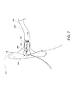
FIG. 7 is an in-ear headphone with a blocked tip. -
FIG. 8 is a graph of acoustic impedance for an unblocked case and a blocked case. -
FIG. 9 is an in-ear headphone configured to detect a blocked tip. -
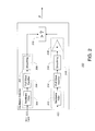
FIG. 10 is a block diagram of a feedback noise reduction including a combined oscillation/blocked tip detector. -
FIG. 11 is a combined oscillation/blocked tip detector. -
FIG. 12 is a truth table showing the logic used to compute the output of the combined oscillation/blocked tip detector. -
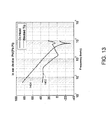
FIG. 13 is a graph of an acoustic impedance metric for an unblocked case and a blocked case. - The system described herein detects actual or potential feedback loop instability due to excessive feedback loop gain in a feedback control based active noise reduction system and mitigates the instability to return the system to a stable or more stable operating state.
- The system leverages the knowledge that:
- a) as the gain of the feedback loop approaches 1 at a frequency where the phase of the feedback loop approaches 180°, the bandwidth of the gain of the feedback loop increases. This reduces the phase margin in the system, ultimately resulting in an unstable feedback loop which can result in oscillation or damped oscillation at that frequency.
- b) when the tip of an earbud is obstructed, a significant change in acoustic impedance occurs, altering the feedback loop gain.
- Upon detection of instability in the feedback loop, the system mitigates the instability by adjusting the gain of the feedback loop.
- Referring to
FIG. 1 , a system for acousticactive noise reduction 200 receives an input signal (e.g., an audio signal), x(t) and provides a modified version of the input signal, to anacoustic driver 102. Theacoustic driver 102 transduces the modified version of the input signal into a sound wave, y (t), in anacoustic cavity 104. In theacoustic cavity 104, y(t) passes through an acoustic transfer function, A 106, between theacoustic driver 102 and afeedback microphone 108. The result of y(t) passing through A 106, combines with a noise sound wave, N(t), to produce ẽ(t). Thefeedback microphone 108 measures ẽ(t), transducing the sound wave into an electrical signal, e(t). This signal is passed along a feedback path, through a feedback factor,H 210. - In a forward path, the input signal, x (t) is provided to a first transfer function block, A1 112. The output of the
feedback factor H 210 is then subtracted from the output of the firsttransfer function block 112. In some examples, the output of A 1 112 includes only (or predominantly) the frequency components of x(t) that are within a desired active noise reduction bandwidth, with the frequencies that are outside the desired active noise reduction bandwidth attenuated. The result of the subtraction is provided to first forward path gain element,G 1 116. - In parallel, the input signal, x(t), is provided to a second transfer function block, A 2 114. The output of the first forward path gain
element G 1 116 is added to the output of the secondtransfer function block 114. In some examples, the output of A 2 114 includes only the frequency components of x(t) that are outside the desired active noise reduction bandwidth, with the frequencies that are within the desired active noise reduction bandwidth attenuated. The result of the addition is provided to a second forward path gain element,G 2 118. The output of the second forwardpath element G 2 118 is provided to theacoustic driver 102. - In some examples, the purpose of injecting different components of the input signal, x(t) into the forward path at different stages is to apply higher gain to components of the input signal which are deemed as more important. For example, the system of
FIG. 1 injects the frequency components of x(t) that are within the active noise reduction bandwidth earlier in the system than those frequency components of x (t) that are outside of the active noise reduction bandwidth. This results in the application of more gain (i.e., bothG 1 116 and G 2 118) to the frequency components that are within the active noise reduction bandwidth and the application of less gain (i.e., only G 2 118) to the frequency components that are outside the active noise reduction bandwidth. Higher feedback gain results in greater noise reduction. - In some examples, x(t) =0 (i.e., no input signal is provided). In such examples, the active noise reduction system reduces ambient noise at the feedback microphone, driving the signal sensed at the microphone to zero.
- In the system shown in
FIG. 1 , e(t) is a measurement of the acoustic signal in the acoustic cavity at the location of thefeedback microphone 108. In the frequency domain, e(t) can be expressed as E(ω) as follows:
- The G 1 G 2 HA term in the denominator is commonly referred to as the feedback loop gain. It is noted that while this term is referred to herein as the "loop gain", the term should be understood as a loop characteristic, including both a frequency dependent gain response of the feedback loop and a frequency dependent phase response of the feedback loop. Thus, a statement such as: "the loop gain equals 1∠180°" should be understood as a loop characteristic where the loop gain at a frequency is equal to 1 and the loop phase is equal to 180°.
- By inspection, one can see that as the gain of the first and second forward path gain
elements FIG. 1 is accomplished using a high loop gain. - Also note that as the first and second forward path gain
elements - Referring to the portions of
FIG. 1 shown in bolded lines, the system includes anoscillation detector 202 that is configured to detect oscillations at the frequency where the loop gain equals 1∠180°. If an oscillation is detected, theoscillation detector 202 can trigger a loop gain adjustment to return the feedback loop to a stable operating state. - The
oscillation detector 202 receives the input signal x (t) and the output of the second forward path gainelement 118, x̃(t) and outputs a control parameter, P to the adjustable feedback factor,H 210. The control parameter, P indicates whether oscillations that are due to instability are present in the feedback loop and commands the feedback factor, H 210 (e.g., by outputting P =HIGH) to adjust the loop gain if necessary. - Referring to
FIG. 2 , theoscillation detector 202 processes x̃(t) and x(t) and compares the resulting processed signals to determine if oscillations are present in the feedback loop that are not present in the input signal. The processing of the signals is based on the knowledge that an oscillation signal due to feedback loop instability typically occurs in a frequency range where the loop gain is near 1∠180°. Furthermore, it is typical that active noise reduction signals are present at lower frequencies than the oscillation signal. - The
oscillation detector 202 processes x̃(t) and x(t) in two separate paths. Adriver signal path 302 applies a band-pass filter 304 to x̃(t), the band-pass filter 304 having a pass-band at the frequency range where oscillation due to instability is expected. The filtered output of the band-pass filter 304 is rectified by afull wave rectifier 306 and smoothed by a smoothing element 308 (e.g., a low pass filter). The result of thedriver signal path 302 is a signal level of x̃(t) in the frequency range where oscillation due to instability is expected. - In the absence of the input signal, x(t), (i.e., when no audio driving signal is provided) the
driver signal path 302 is sufficient for detecting oscillations due to instability in the feedback loop. However, in the presence of the input signal, x(t) it is necessary to process both x(t) and x̃(t). This is due to the fact that the input signal x(t) (e.g., an audio signal), may include frequency components which are present in the frequency range where oscillation is expected. In the presence of such an input signal, false instability detection results may occur. - Thus, to improve the robustness of the system, x(t) is processed in a
reference signal path 310 for the purpose of establishing a dynamic threshold reference. The reference signal path applies a band-pass filter 312 to x (t), the band-pass filter 312 having a pass band at the frequency range where oscillation due to instability is expected. The filtered output of the band-pass filter 312 is rectified by afull wave rectifier 314 and smoothed by a smoothing element 316 (e.g., a low pass filter). - The output of the smoothing
element 316 is a signal level of x(t) in the frequency range where oscillation due to instability is expected. This output is scaled by a scale factor,K 318, such that the output of thereference signal path 310 is slightly greater than the output of thedriver signal path 302 when x(t) is present and no oscillation is present in the feedback loop. - The output of the
driver signal path 302 and the output of thereference signal path 310 are provided to adifferential detector 320 which outputs a value of P = HIGH if the output of thedriver signal path 302 is greater than the output of the reference signal path 310 (i.e., oscillation is present) and a P =LOW if the output of thedriver signal path 302 is less than the output of the reference signal path 310 (i.e., no oscillation is present). - Parameter P (e.g., a HIGH or LOW output) output by the
oscillation detector 202 is provided to the adjustable feedback factor, H (FIG. 1 , element 210). In some examples, theadjustable feedback factor 210 is adjusted, based on the parameter P to modify the overall feedback loop gain of the system across all or a wide range of frequencies. In other examples, theadjustable feedback factor 210 is adjusted, based on the parameter P to modify the bandwidth of the feedback loop gain, for example by reducing the gain over a limited range of frequencies. In some examples, the modification of the feedback loop gain is maintained for a predetermined amount of time. After the predetermined amount of time (e.g., 3 seconds) has elapsed, the modification of the feedback loop gain is reversed. - Referring to
FIG. 3 , an example of a feedback loop gain and phase response illustrates an unstable situation in the feedback loop of the system ofFIG. 1 . In particular, the feedback loop is in an unstable situation due to thesolid gain curve 420 being equal to 1 and thesolid phase curve 422 being equal to 180° at the frequency ω u . In this situation, the phase margin is 0°, causing instability. - In some examples, the
adjustable feedback factor 210 is configurable to mitigate this instability by reducing the gain by a predetermined amount based on the parameter P received from theinstability detector 202. In particular, if P indicates that the phase margin is at or near 0° (i.e., the instability detector outputs a HIGH parameter value), the feedback factor reduces the overall gain by a predetermined amount. - The dashed
gain curve 424 is the result of an overall reduction of the feedback loop gain. Since thephase curve 422 is not changed, reducing the overall loop gain results in an increasedphase margin 426, returning the feedback loop to a stable operating state. - Referring to
FIG. 4 , a circuit is configured to reduce the overall loop gain passed on P. The overall reduction in loop gain is achieved by a P =HIGH output from theinstability detector 202 turning on amosfet 530 at thefeedback microphone 108, thereby reducing the loop gain at thefeedback microphone input 108. - Referring to
FIG. 5 , another example of a feedback loop gain and phase response illustrates an unstable situation in the feedback loop of the system ofFIG. 1 . In particular, the feedback loop is in an unstable situation due to afirst gain curve 620 having a value of 0 dB at a frequency, ω u , where afirst phase curve 622 has a value close to -180°. In this situation, the phase margin is reduced, causing instability. - In some examples, the
adjustable feedback factor 210 is configurable to switch the feedback loop gain between a high bandwidth mode and a low bandwidth mode based on the parameter P. The high bandwidth mode is used during normal operation of the system and the low bandwidth mode is used when a system change places the system in a potentially unstable operating state. If the parameter, P indicates that the bandwidth of the feedback loop needs to be reduced (i.e., the instability detector outputs a P =HIGH parameter value), the adjustable feedback factor enables a low-pass filtering operation in the feedback path. - A second
loop gain curve 624 shows a reduction in the loop gain at high frequencies with little effect on the loop gain at low frequencies. Such a reduction in the bandwidth of the loop gain results in an increased thephase margin 626 while having less impact on the audio output quality of the system when compared to the previously described overall reduction in loop gain. - Referring to
FIG. 6 , one example of theadjustable feedback factor 210 achieves the low bandwidth mode of the feedback loop gain by switching in a simple pole-zerolow pass network 740 into the existing high bandwidth feedback loop upon detection of a potentially unstable operating state. - For example, the parameter output, P of the instability detector (
FIG. 1 , element 202) can be provided to mosfet,M1 742 such that a HIGH parameter value switchesM1 742 to an on state. WhenM1 742 is on, anRC network RC network effective output impedance 748 of thefeedback microphone 108 forms a low-pass filter. - The low-pass filter formed by the
RC network effective impedance 748 of thefeedback microphone 108 includes a zero break (caused by the inclusion of resistor R331 744). The zero break halts phase lag in the low-pass filter at higher frequencies, resulting in a higher stability margin. - The
adjustable feedback factor 210 described above can be implemented using analog or digital electronics. In some examples, the parameter output P of theinstability detector 202 is used to switch a compensation filter with a different transfer function than those described above into the system. In some examples a different compensation filter is used based on whether the adjustable feedback factor is implemented using analog electronics or digital electronics (e.g., dedicated DSP hardware). - Referring to
FIG. 7 , anearbud 850 of an active noise reduction headphone system is configured to be inserted into anear canal 852 of awearer 854. When inserted, theearbud 850 presses outward against the inner walls of the wearer'sear canal 852, creating a sealedcavity 856 within theear canal 852. Theearbud 850 includes aninner cavity 858 which extends from anacoustic driver 860 in the earbud into the sealedcavity 856 within theear canal 852. - At the end of the
inner cavity 858 of theearbud 850 opposite the acoustic driver ablockage 862 obstructs the opening of theinner cavity 858 into thecavity 856 within theear canal 852. Such ablockage 862 commonly arises while thewearer 854 is inserting theearbud 850 into theear canal 852 and can be referred to as a "blocked tip." - Referring to
FIG. 8 one indication of a blocked tip is increased acoustic impedance in the inner cavity (FIG. 7 , element 858) of the earbud (FIG. 7 , element 850). The On-Head curve 970 in the graph shows the acoustic impedance of anearbud 850 without a blocked tip and the BlockedTip curve 972 in the graph shows the acoustic impedance of anearbud 850 with a blocked tip. By inspection it is easily ascertained that the acoustic impedance in the blocked tip case is significantly increased. - Referring to
FIG. 9 , one method of detecting such a change in acoustic impedance is to use avelocity microphone 1080 in addition to thepressure microphone 1082 that is already used as the feedback microphone (FIG. 1 , element 108) for the active noise reduction system (i.e., the system ofFIG. 1 ). - The equation for acoustic impedance is:

- Thus, acoustic impedance is determined by placing the
velocity microphone 1080 in close proximity to thepressure microphone 1082 and calculating a ratio between the two microphone signals in a specified frequency range. If the acoustic impedance is determined to exceed a predetermined threshold, the tip of the earbud is likely blocked. - This method is not influenced by the nature of the sound waves emitted by the
acoustic driver 860 inside theinner cavity 858 of the earbud 850 (e.g., noise, speech, audio). However, to calculate the ratio, sufficient acoustic signal must be present in theinner cavity 858 of theearbud 850. - To determine whether sufficient acoustic signal is present in the
inner cavity 858 of the earbud, anadditional pressure microphone 1084 can be included in theearbud 850 such that it is outside of both theinner cavity 858 of theearbud 850 and the cavity within theear canal 856. Thismicrophone 1084 can detect the pressure outside of theear cavity 856 and use it to determine whether the calculated impedance is reliable. For example, the calculated impedance is considered reliable if the outside pressure exceeds a certain predetermined threshold. - Referring to
FIG. 10 , theoscillation detector 202 of the system ofFIG. 1 , is augmented with the blocked tip detection algorithm described above, resulting in asystem 1100 which includes a combined oscillation/blockedtip detector 1110 according to an embodiment of the invention. - The basic operation of the feedback loop of the
system 1100 is much the same as was described in reference to the feedback loop of thesystem 100 shown inFIG. 1 and therefore will not be repeated in this section. - The combined oscillation/blocked
tip detector 1110 receives input from the input signal, x(t) the driver output signal x̃(t), the feedback pressure microphone,M1 108, a feedback velocity microphone,M2 1080, and an outside pressure microphone,M3 1084. The output of the combined oscillation/blockedtip detector 1110 is a parameter, P which has a value of HIGH if either oscillations due to instability or a blocked tip is detected. Otherwise, P has a value of LOW. As was described above with respect to the system ofFIG. 1 , P is provided to the adjustablefeedback factor H 210 which in turn adjusts the feedback loop gain or bandwidth to mitigate instability in the feedback loop. - Referring to
FIG. 11 , a detailed block diagram of the oscillation/blockedtip detector 1110 includes theoscillation detector 1202 described above, a blockedtip detector 1204, and anoutside pressure detector 1206. The results of theoscillation detector 1202, blockedtip detector 1204, and outsidepressure detector 1206 are processed usingBoolean logic 1208 to produce a HIGH parameter value if an oscillation or a blocked tip is detected. Otherwise theBoolean logic 1208 produces a LOW parameter value. - The blocked
tip detector 1204 receives as input the feedback pressure microphone signal M 1(t) and the velocity microphone signal M 2(t). M 1(t) is filtered by a first band-pass filter 1210, rectified by a firstfull wave rectifier 1212, and smoothed by afirst smoothing element 1214. M 2(t) is filtered by a second band-pass filter 1216, rectified by a secondfull wave rectifier 1218, and smoothed by asecond smoothing element 1220. - Band-pass filtering, rectification, and smoothing of the microphone input signals M1(t) and M 2(t) results in an estimate of the signal level in a frequency of interest (e.g., a frequency where it is known that a blocked tip significantly increases acoustic impedance). The processed versions of M 1(t) is divided by the processed version of M 2(t), yielding an estimate of the acoustic impedance in the vicinity of the microphones (
FIG. 10 ,elements 108, 1080). The estimate of the acoustic impedance is compared to an acoustic impedance threshold, Vz_Ref. If the estimate of the acoustic impedance is greater than the reference threshold, the blockedtip detector 1204 outputs a HIGH value indicating that the tip is likely blocked. Otherwise, the blocked tip detector outputs a LOW value. - The outside
pressure level detector 1206 receives as input the outside pressure microphone signal M 3(t). M 3(t) is filtered by a third band-pass filter 1222, rectified by a thirdfull wave rectifier 1224, and smoothed by athird smoothing element 1226. The output of thethird smoothing element 1226 is an estimate of the sound pressure level outside of the ear cavity. The estimate of the sound pressure level outside of the ear cavity is compared to a outside pressure threshold V Pout_Ref . If the estimate of the sound pressure level outside of the ear cavity is greater than the outside pressure threshold, the outsidepressure level detector 1206 outputs a HIGH value indicating that result of the blockedtip detector 1204 is valid. Otherwise, the outsidepressure level detector 1206 outputs a LOW value indicating that the result of the blockedtip detector 1204 is invalid. - The HIGH or LOW outputs of the blocked
tip detector 1204,oscillation detector 1202, and the outsidepressure level detector 1206 are used as input toBoolean logic 1208 which determines the output, P of the blocked tip/oscillation detector 1110. - Referring to
FIG. 12 , a truth table illustrates the result of applying the following Boolean logic to the outputs of the blockedtip detector 1204,oscillation detector 1202, and outside pressure level detector 1206:
- In some examples, a microcontroller can be used to interpret the outputs of one or more of the oscillation detector, blocked tip detector, and outside pressure level detector and take action to reduce the loop gain.
- In some examples, a dedicated digital signal processor or microcontroller performs the band-pass filtering, peak detection, comparator function, and gain reduction function.
- Referring to
FIG. 13 , in some examples, instead of using a velocity microphone in conjunction with the feedback pressure microphone to calculate acoustic impedance, a second pressure microphone is placed inside the cavity (e.g., near the tip of the nozzle). The acoustic impedance can be calculated as the ratio P1 / (P1 - P2).FIG. 13 shows impedance curves calculated using this method.Curve 1402 is the impedance curve representing an unblocked tip.Curve 1404 is the impedance curve representing a blocked tip. - In some examples, a change in acoustic impedance is detected by monitoring the electrical input impedance at the driver. In some examples, due to characteristics of the driver an acoustic to electric transformation ratio is relatively small, resulting in a poor signal to noise ratio. However, characteristics of the driver can be adjusted to yield a larger acoustic to electric transformation ratio resulting in an improved signal to noise ratio.
- The above description focuses on a single channel of an in-ear headphone system. However, it is noted that the system described above can be extended to two or more channels.
- Just as the oscillation detector can be used to detect instability without the use of the blocked tip detector, the blocked tip detector can be used alone to detect a potential instability without the use of the oscillation detector. Neither depends on the other and each can be effectively used independently.
- Although described in the context of an in-ear active noise cancellation system, the approaches described above can be applied in other situations. For example, the approaches can be applied to over-the-ear noise cancellation headphones. More generally, the approaches may be applied to other audio feedback situations, particularly when characteristics of an audio component of a feedback path may vary, for example the audio characteristics of a room or a vehicle passenger compartment may change (e.g., when a door or window is opened). Furthermore, the method of oscillation and impedance detection described above may be applied to motion control systems where feedback loop oscillation and mechanical impedance (e.g., velocity/force) can be detected and measured.
- In the above description, the feedback loop gain is adjusted by modifying a feedback factor in the feedback path. In some examples, instead of adjusting the feedback loop gain in the feedback path, the forward path gain elements can be adjusted.
- In some examples, the circuitry to implement the approaches described above is integrated into a housing including the drivers and microphones. In other examples, the circuitry is provided separately, and may be configurable to be suitable for different housings and arrangements of drivers and microphones.
- In some examples, in active noise reduction systems which include feedback, feedforward, and audio input filtering, it is desirable to modify the filter transfer functions of all three of the filters (i.e., the audio input filter, the feedforward filter, and the feedback filter) concurrently when the instability/oscillation detector is activated. Modifying the transfer function of all three filters concurrently compensates for the entire system response due to a change in the feedback loop gain response. Such a modification of filter transfer functions can occur in both analog hardware or DSP based systems.
- It is to be understood that the foregoing description is intended to illustrate and not to limit the scope of the invention, which is defined by the scope of the appended claims. Other embodiments are within the scope of the following claims.
Claims (15)
- A feedback based active noise reduction system (200) comprising:a feedback element (210) including
a feedback input for accepting a first feedback signal from a first sensor (108),
a control input for accepting a control parameter (P) for adjusting a gain characteristic and a phase characteristic of the feedback element (210),
and
a driver output for providing a driver signal to a driver (102); andan instability detector (1110) for detecting an instability condition in the feedback element (210) and forming the control parameter (P) based on a result of the detection, the instability detector (1110) including
a control parameter output for providing the control parameter (P) to the control parameter input of the feedback element (210), and
a plurality of inputs for accepting a plurality of feedback signals from a plurality of sensors including the first sensor (108) and a second sensor (1080),
wherein detecting the instability condition includes processing the plurality of feedback signals to determine a characteristic of an acoustic path between the driver (102) and the first sensor (108) based on a ratio of the first feedback signal associated with the first sensor (108) to a second feedback signal associated with the second sensor (1080). - The system (200) of claim 1 wherein the first sensor (108) includes a microphone and the driver (102) includes a loudspeaker.
- The system (200) of claim 1 wherein the feedback element (210) is configured to cause one or both of the gain characteristic and the phase characteristic of the feedback element (210) to change by a predetermined amount upon providing of the control parameter (P).
- The system (200) of claim 1 comprising a feedback filter (210, H), a feedforward filter (112, A1), and an audio input filter (114, A2) and wherein the feedback element (210) is configured to concurrently modify a transfer function of the feedback filter (210, H), the feedforward filter (112, A1), and the audio input filter (114, A2) upon providing of the control parameter (P).
- The system (200) of claim 1 wherein the feedback element (210) is configured to cause a bandwidth of the feedback element gain to change by a predetermined amount upon providing of the control parameter (P).
- The system (200) of claim 1 wherein the feedback element (210) further comprises a low-pass filter selectably applicable to the feedback element (210) according to the control parameter (P).
- The system (200) of claim 1 wherein the ratio of the first feedback signal to the second feedback signal represents an acoustic impedance of the acoustic path.
- The system (200) of claim 1 wherein the first sensor (108) includes a pressure microphone and the second sensor (1080) includes a velocity microphone.
- The system (200) of claim 1 wherein the first sensor (108) includes a pressure microphone and the second sensor (1080) includes a pressure microphone.
- The system (200) of claim 1 wherein the plurality of sensors includes a third sensor (1084) for producing a third feedback signal and the instability detector is configured to determine the validity of the instability condition detected by the instability detector based on the third feedback signal.
- The system (200) of claim 1 wherein the feedback element (210) further includes a first signal input for accepting an audio input signal, the instability detector further includes a second signal input for accepting the audio input signal and a driver input for accepting the driver signal, and the instability detector is configured to detect the instability condition in the feedback element (210) including determining a characteristic of the feedback element (210) based on the audio input signal and the driver signal.
- The system (200) of claim 11 wherein the instability condition includes the presence of an oscillation in a specified frequency range.
- The system (200) of claim 12 wherein the specified frequency range is mutually exclusive from a frequency range where active noise reduction occurs.
- The system (200) of claim 12 wherein the instability detector is configured to analyze the input signal and driver signal to determine whether the oscillation is present in the driver signal and that the oscillation is not present in the input signal
- A method for detecting and avoiding instability in a feedback based active noise reduction system (200), the method comprising:detecting an instability condition in a feedback element (210) and forming a control parameter (P) based on the result of the detection, detecting the instability condition including accepting a plurality of feedback signals from a plurality of sensors including a first sensor (108) and a second sensor (1080); and processing the plurality of feedback signals to determine a characteristic of an acoustic path between a driver (102) and the first sensor (108) by calculating a ratio of the first feedback signal associated with the first sensor to a second feedback signal associated with the second (1080);providing the control parameter (P) to the feedback element (201); accepting, at the feedback element (210), the control parameter (P); accepting, at the feedback element (210), a first feedback signal from the first sensor (108); adjusting a gain characteristic and a phase characteristic of the feedback element (210) based on the control parameter (P); and outputting, from the feedback element (210), a driver output signal to the driver (102).
Applications Claiming Priority (2)
| Application Number | Priority Date | Filing Date | Title |
|---|---|---|---|
| US13/251,725 US8824695B2 (en) | 2011-10-03 | 2011-10-03 | Instability detection and avoidance in a feedback system |
| PCT/US2012/057250 WO2013052327A2 (en) | 2011-10-03 | 2012-09-26 | Instability detection and avoidance in a feedback system |
Publications (2)
| Publication Number | Publication Date |
|---|---|
| EP2764707A2 EP2764707A2 (en) | 2014-08-13 |
| EP2764707B1 true EP2764707B1 (en) | 2015-07-01 |
Family
ID=47008685
Family Applications (1)
| Application Number | Title | Priority Date | Filing Date |
|---|---|---|---|
| EP12770397.3A Active EP2764707B1 (en) | 2011-10-03 | 2012-09-26 | Instability detection and avoidance in a feedback system |
Country Status (6)
| Country | Link |
|---|---|
| US (1) | US8824695B2 (en) |
| EP (1) | EP2764707B1 (en) |
| JP (1) | JP5813239B2 (en) |
| CN (1) | CN103843364B (en) |
| MY (1) | MY170985A (en) |
| WO (1) | WO2013052327A2 (en) |
Families Citing this family (43)
| Publication number | Priority date | Publication date | Assignee | Title |
|---|---|---|---|---|
| US7668325B2 (en) | 2005-05-03 | 2010-02-23 | Earlens Corporation | Hearing system having an open chamber for housing components and reducing the occlusion effect |
| EP2208367B1 (en) | 2007-10-12 | 2017-09-27 | Earlens Corporation | Multifunction system and method for integrated hearing and communiction with noise cancellation and feedback management |
| KR101568452B1 (en) | 2008-06-17 | 2015-11-20 | 이어렌즈 코포레이션 | Optical electro-mechanical hearing devices with separate power and signal components |
| WO2010033932A1 (en) | 2008-09-22 | 2010-03-25 | Earlens Corporation | Transducer devices and methods for hearing |
| WO2012088187A2 (en) | 2010-12-20 | 2012-06-28 | SoundBeam LLC | Anatomically customized ear canal hearing apparatus |
| US8831239B2 (en) * | 2012-04-02 | 2014-09-09 | Bose Corporation | Instability detection and avoidance in a feedback system |
| US9047855B2 (en) * | 2012-06-08 | 2015-06-02 | Bose Corporation | Pressure-related feedback instability mitigation |
| CN103391496B (en) * | 2013-07-16 | 2016-08-10 | 歌尔声学股份有限公司 | It is applied to active noise and eliminates the chauvent's criterion method and apparatus of ANR earphone |
| US10034103B2 (en) * | 2014-03-18 | 2018-07-24 | Earlens Corporation | High fidelity and reduced feedback contact hearing apparatus and methods |
| FR3019961A1 (en) * | 2014-04-11 | 2015-10-16 | Parrot | AUDIO HEADSET WITH ANC ACTIVE NOISE CONTROL WITH REDUCTION OF THE ELECTRICAL BREATH |
| DK3169396T3 (en) | 2014-07-14 | 2021-06-28 | Earlens Corp | Sliding bias and peak limitation for optical hearing aids |
| US9654855B2 (en) * | 2014-10-30 | 2017-05-16 | Bose Corporation | Self-voice occlusion mitigation in headsets |
| US9924276B2 (en) | 2014-11-26 | 2018-03-20 | Earlens Corporation | Adjustable venting for hearing instruments |
| US10575117B2 (en) * | 2014-12-08 | 2020-02-25 | Harman International Industries, Incorporated | Directional sound modification |
| US9622013B2 (en) * | 2014-12-08 | 2017-04-11 | Harman International Industries, Inc. | Directional sound modification |
| CN104811158B (en) * | 2015-04-27 | 2017-05-24 | 电子科技大学 | Design method of driving circuit of piezoelectric acoustic wave resonant type sensor |
| TWI533822B (en) * | 2015-09-10 | 2016-05-21 | 中原大學 | Electronic pillow pad and method thereof for cancelling snore and noises |
| WO2017059240A1 (en) | 2015-10-02 | 2017-04-06 | Earlens Corporation | Drug delivery customized ear canal apparatus |
| US10492010B2 (en) | 2015-12-30 | 2019-11-26 | Earlens Corporations | Damping in contact hearing systems |
| US11350226B2 (en) | 2015-12-30 | 2022-05-31 | Earlens Corporation | Charging protocol for rechargeable hearing systems |
| US10306381B2 (en) | 2015-12-30 | 2019-05-28 | Earlens Corporation | Charging protocol for rechargable hearing systems |
| US9747887B2 (en) | 2016-01-12 | 2017-08-29 | Bose Corporation | Systems and methods of active noise reduction in headphones |
| US9812114B2 (en) * | 2016-03-02 | 2017-11-07 | Cirrus Logic, Inc. | Systems and methods for controlling adaptive noise control gain |
| CN112738700A (en) | 2016-09-09 | 2021-04-30 | 伊尔兰斯公司 | Smart mirror system and method |
| WO2018093733A1 (en) | 2016-11-15 | 2018-05-24 | Earlens Corporation | Improved impression procedure |
| CN110313186B (en) * | 2017-01-05 | 2021-07-06 | 美商楼氏电子有限公司 | Acoustic devices, acoustic receivers and integrated circuits |
| US11039236B2 (en) | 2017-05-23 | 2021-06-15 | Nec Platforms, Ltd. | Ear pad and earphone using the same |
| WO2019173470A1 (en) | 2018-03-07 | 2019-09-12 | Earlens Corporation | Contact hearing device and retention structure materials |
| WO2019199680A1 (en) | 2018-04-09 | 2019-10-17 | Earlens Corporation | Dynamic filter |
| US10885896B2 (en) | 2018-05-18 | 2021-01-05 | Bose Corporation | Real-time detection of feedforward instability |
| US10244306B1 (en) * | 2018-05-24 | 2019-03-26 | Bose Corporation | Real-time detection of feedback instability |
| CN110597477B (en) * | 2018-06-12 | 2024-05-28 | 哈曼国际工业有限公司 | Directional Sound Modification |
| CN109040889B (en) * | 2018-07-27 | 2020-01-10 | 歌尔科技有限公司 | Feedback noise reduction earphone and feedback circuit thereof |
| CN108882094B (en) * | 2018-07-27 | 2020-03-13 | 歌尔科技有限公司 | Feedback noise reduction earphone and feedback circuit thereof |
| CN112840670B (en) | 2018-09-07 | 2022-11-08 | 杜比实验室特许公司 | Dynamic environment overlay instability detection and suppression in media compensated pass-through devices |
| CN110087159B (en) | 2019-04-03 | 2020-11-17 | 歌尔科技有限公司 | Feedback noise reduction method, system, earphone and storage medium |
| US10959019B1 (en) | 2019-09-09 | 2021-03-23 | Bose Corporation | Active noise reduction audio devices and systems |
| US11043201B2 (en) | 2019-09-13 | 2021-06-22 | Bose Corporation | Synchronization of instability mitigation in audio devices |
| US11350204B2 (en) * | 2020-08-14 | 2022-05-31 | Bose Corporation | Wearable audio device feedforward instability detection |
| CN113473290B (en) * | 2021-06-28 | 2023-11-07 | 北京安声浩朗科技有限公司 | Active noise reduction earphone |
| US11457304B1 (en) * | 2021-12-27 | 2022-09-27 | Bose Corporation | Headphone audio controller |
| US11961502B1 (en) * | 2023-08-15 | 2024-04-16 | Bose Corporation | Wearable audio device with feedback instability control |
| WO2025038203A1 (en) * | 2023-08-15 | 2025-02-20 | Bose Corporation | Wearable audio device with feedback instability control |
Family Cites Families (15)
| Publication number | Priority date | Publication date | Assignee | Title |
|---|---|---|---|---|
| ZA825676B (en) * | 1981-08-11 | 1983-06-29 | Sound Attenuators Ltd | Method and apparatus for low frequency active attennuation |
| JPH06503897A (en) * | 1990-09-14 | 1994-04-28 | トッドター、クリス | Noise cancellation system |
| US7103188B1 (en) | 1993-06-23 | 2006-09-05 | Owen Jones | Variable gain active noise cancelling system with improved residual noise sensing |
| US20010036283A1 (en) * | 2000-03-07 | 2001-11-01 | Mark Donaldson | Active noise reduction system |
| SG106582A1 (en) * | 2000-07-05 | 2004-10-29 | Univ Nanyang | Active noise control system with on-line secondary path modeling |
| JP4887060B2 (en) * | 2006-03-07 | 2012-02-29 | シャープ株式会社 | Noise canceling headphones |
| CA2647462C (en) * | 2006-04-01 | 2014-05-20 | Widex A/S | Hearing aid, and a method for control of adaptation rate in anti-feedback systems for hearing aids |
| US20110002474A1 (en) | 2009-01-29 | 2011-01-06 | Graeme Colin Fuller | Active Noise Reduction System Control |
| CN103996398B (en) | 2009-04-28 | 2017-05-24 | 伯斯有限公司 | Sound-dependent anr signal processing adjustment |
| US8611553B2 (en) * | 2010-03-30 | 2013-12-17 | Bose Corporation | ANR instability detection |
| US8315405B2 (en) | 2009-04-28 | 2012-11-20 | Bose Corporation | Coordinated ANR reference sound compression |
| US8165313B2 (en) * | 2009-04-28 | 2012-04-24 | Bose Corporation | ANR settings triple-buffering |
| US9165549B2 (en) * | 2009-05-11 | 2015-10-20 | Koninklijke Philips N.V. | Audio noise cancelling |
| US8229372B2 (en) * | 2010-03-16 | 2012-07-24 | Motorola Solutions, Inc. | Parallel forward path cartesian feedback loop and loop filter with switchable order for cartesian feedback loops |
| US8831239B2 (en) * | 2012-04-02 | 2014-09-09 | Bose Corporation | Instability detection and avoidance in a feedback system |
-
2011
- 2011-10-03 US US13/251,725 patent/US8824695B2/en active Active
-
2012
- 2012-09-26 CN CN201280048628.8A patent/CN103843364B/en active Active
- 2012-09-26 WO PCT/US2012/057250 patent/WO2013052327A2/en not_active Ceased
- 2012-09-26 MY MYPI2014700670A patent/MY170985A/en unknown
- 2012-09-26 JP JP2014534603A patent/JP5813239B2/en active Active
- 2012-09-26 EP EP12770397.3A patent/EP2764707B1/en active Active
Also Published As
| Publication number | Publication date |
|---|---|
| EP2764707A2 (en) | 2014-08-13 |
| CN103843364B (en) | 2017-05-24 |
| WO2013052327A3 (en) | 2013-10-10 |
| US8824695B2 (en) | 2014-09-02 |
| MY170985A (en) | 2019-09-23 |
| CN103843364A (en) | 2014-06-04 |
| JP2014532199A (en) | 2014-12-04 |
| WO2013052327A2 (en) | 2013-04-11 |
| JP5813239B2 (en) | 2015-11-17 |
| US20130083938A1 (en) | 2013-04-04 |
Similar Documents
| Publication | Publication Date | Title |
|---|---|---|
| US8824695B2 (en) | Instability detection and avoidance in a feedback system | |
| EP2834994B1 (en) | Instability detection and avoidance in a feedback system | |
| CN103460715B (en) | Active noise reduction equipment and method | |
| EP3712883B1 (en) | Audio system and signal processing method for an ear mountable playback device | |
| US8218802B2 (en) | Hearing aid having an occlusion reduction unit and method for occlusion reduction | |
| CN110326305A (en) | In-Ear Headphones are detected from head | |
| CN101621730A (en) | Apparatus and method for detecting acoustic feedback | |
| WO2020223554A1 (en) | Wind noise suppression for active noise cancelling systems and methods | |
| EP3899926B1 (en) | Robust adaptive noise cancelling systems and methods | |
| US11049487B2 (en) | Robust adaptive noise cancelling systems and methods | |
| US11039247B2 (en) | Extended bandwidth adaptive noise cancelling system and methods | |
| JP6143554B2 (en) | Active noise control device | |
| US11568844B2 (en) | Noise control system, a noise control device and a method thereof | |
| US11763791B2 (en) | Noise amplification control in adaptive noise cancelling systems | |
| HK1194586A (en) | Instability detection and avoidance in a feedback system | |
| HK1194586B (en) | Instability detection and avoidance in a feedback system | |
| EP3712885B1 (en) | Audio system and signal processing method of voice activity detection for an ear mountable playback device |
Legal Events
| Date | Code | Title | Description |
|---|---|---|---|
| PUAI | Public reference made under article 153(3) epc to a published international application that has entered the european phase |
Free format text: ORIGINAL CODE: 0009012 |
|
| 17P | Request for examination filed |
Effective date: 20140317 |
|
| AK | Designated contracting states |
Kind code of ref document: A2 Designated state(s): AL AT BE BG CH CY CZ DE DK EE ES FI FR GB GR HR HU IE IS IT LI LT LU LV MC MK MT NL NO PL PT RO RS SE SI SK SM TR |
|
| DAX | Request for extension of the european patent (deleted) | ||
| GRAP | Despatch of communication of intention to grant a patent |
Free format text: ORIGINAL CODE: EPIDOSNIGR1 |
|
| INTG | Intention to grant announced |
Effective date: 20150320 |
|
| GRAS | Grant fee paid |
Free format text: ORIGINAL CODE: EPIDOSNIGR3 |
|
| GRAA | (expected) grant |
Free format text: ORIGINAL CODE: 0009210 |
|
| AK | Designated contracting states |
Kind code of ref document: B1 Designated state(s): AL AT BE BG CH CY CZ DE DK EE ES FI FR GB GR HR HU IE IS IT LI LT LU LV MC MK MT NL NO PL PT RO RS SE SI SK SM TR |
|
| REG | Reference to a national code |
Ref country code: GB Ref legal event code: FG4D |
|
| REG | Reference to a national code |
Ref country code: AT Ref legal event code: REF Ref document number: 734565 Country of ref document: AT Kind code of ref document: T Effective date: 20150715 Ref country code: CH Ref legal event code: EP |
|
| REG | Reference to a national code |
Ref country code: IE Ref legal event code: FG4D |
|
| REG | Reference to a national code |
Ref country code: DE Ref legal event code: R096 Ref document number: 602012008455 Country of ref document: DE |
|
| REG | Reference to a national code |
Ref country code: AT Ref legal event code: MK05 Ref document number: 734565 Country of ref document: AT Kind code of ref document: T Effective date: 20150701 |
|
| REG | Reference to a national code |
Ref country code: NL Ref legal event code: MP Effective date: 20150701 |
|
| REG | Reference to a national code |
Ref country code: LT Ref legal event code: MG4D |
|
| PG25 | Lapsed in a contracting state [announced via postgrant information from national office to epo] |
Ref country code: GR Free format text: LAPSE BECAUSE OF FAILURE TO SUBMIT A TRANSLATION OF THE DESCRIPTION OR TO PAY THE FEE WITHIN THE PRESCRIBED TIME-LIMIT Effective date: 20151002 Ref country code: NO Free format text: LAPSE BECAUSE OF FAILURE TO SUBMIT A TRANSLATION OF THE DESCRIPTION OR TO PAY THE FEE WITHIN THE PRESCRIBED TIME-LIMIT Effective date: 20151001 Ref country code: FI Free format text: LAPSE BECAUSE OF FAILURE TO SUBMIT A TRANSLATION OF THE DESCRIPTION OR TO PAY THE FEE WITHIN THE PRESCRIBED TIME-LIMIT Effective date: 20150701 Ref country code: LT Free format text: LAPSE BECAUSE OF FAILURE TO SUBMIT A TRANSLATION OF THE DESCRIPTION OR TO PAY THE FEE WITHIN THE PRESCRIBED TIME-LIMIT Effective date: 20150701 Ref country code: LV Free format text: LAPSE BECAUSE OF FAILURE TO SUBMIT A TRANSLATION OF THE DESCRIPTION OR TO PAY THE FEE WITHIN THE PRESCRIBED TIME-LIMIT Effective date: 20150701 |
|
| PG25 | Lapsed in a contracting state [announced via postgrant information from national office to epo] |
Ref country code: AT Free format text: LAPSE BECAUSE OF FAILURE TO SUBMIT A TRANSLATION OF THE DESCRIPTION OR TO PAY THE FEE WITHIN THE PRESCRIBED TIME-LIMIT Effective date: 20150701 Ref country code: IS Free format text: LAPSE BECAUSE OF FAILURE TO SUBMIT A TRANSLATION OF THE DESCRIPTION OR TO PAY THE FEE WITHIN THE PRESCRIBED TIME-LIMIT Effective date: 20151101 Ref country code: HR Free format text: LAPSE BECAUSE OF FAILURE TO SUBMIT A TRANSLATION OF THE DESCRIPTION OR TO PAY THE FEE WITHIN THE PRESCRIBED TIME-LIMIT Effective date: 20150701 Ref country code: RS Free format text: LAPSE BECAUSE OF FAILURE TO SUBMIT A TRANSLATION OF THE DESCRIPTION OR TO PAY THE FEE WITHIN THE PRESCRIBED TIME-LIMIT Effective date: 20150701 Ref country code: SE Free format text: LAPSE BECAUSE OF FAILURE TO SUBMIT A TRANSLATION OF THE DESCRIPTION OR TO PAY THE FEE WITHIN THE PRESCRIBED TIME-LIMIT Effective date: 20150701 Ref country code: PT Free format text: LAPSE BECAUSE OF FAILURE TO SUBMIT A TRANSLATION OF THE DESCRIPTION OR TO PAY THE FEE WITHIN THE PRESCRIBED TIME-LIMIT Effective date: 20151102 Ref country code: PL Free format text: LAPSE BECAUSE OF FAILURE TO SUBMIT A TRANSLATION OF THE DESCRIPTION OR TO PAY THE FEE WITHIN THE PRESCRIBED TIME-LIMIT Effective date: 20150701 Ref country code: ES Free format text: LAPSE BECAUSE OF FAILURE TO SUBMIT A TRANSLATION OF THE DESCRIPTION OR TO PAY THE FEE WITHIN THE PRESCRIBED TIME-LIMIT Effective date: 20150701 |
|
| REG | Reference to a national code |
Ref country code: DE Ref legal event code: R097 Ref document number: 602012008455 Country of ref document: DE |
|
| PG25 | Lapsed in a contracting state [announced via postgrant information from national office to epo] |
Ref country code: CZ Free format text: LAPSE BECAUSE OF FAILURE TO SUBMIT A TRANSLATION OF THE DESCRIPTION OR TO PAY THE FEE WITHIN THE PRESCRIBED TIME-LIMIT Effective date: 20150701 Ref country code: IT Free format text: LAPSE BECAUSE OF FAILURE TO SUBMIT A TRANSLATION OF THE DESCRIPTION OR TO PAY THE FEE WITHIN THE PRESCRIBED TIME-LIMIT Effective date: 20150701 Ref country code: SK Free format text: LAPSE BECAUSE OF FAILURE TO SUBMIT A TRANSLATION OF THE DESCRIPTION OR TO PAY THE FEE WITHIN THE PRESCRIBED TIME-LIMIT Effective date: 20150701 Ref country code: LU Free format text: LAPSE BECAUSE OF FAILURE TO SUBMIT A TRANSLATION OF THE DESCRIPTION OR TO PAY THE FEE WITHIN THE PRESCRIBED TIME-LIMIT Effective date: 20150926 Ref country code: MC Free format text: LAPSE BECAUSE OF FAILURE TO SUBMIT A TRANSLATION OF THE DESCRIPTION OR TO PAY THE FEE WITHIN THE PRESCRIBED TIME-LIMIT Effective date: 20150701 Ref country code: EE Free format text: LAPSE BECAUSE OF FAILURE TO SUBMIT A TRANSLATION OF THE DESCRIPTION OR TO PAY THE FEE WITHIN THE PRESCRIBED TIME-LIMIT Effective date: 20150701 Ref country code: DK Free format text: LAPSE BECAUSE OF FAILURE TO SUBMIT A TRANSLATION OF THE DESCRIPTION OR TO PAY THE FEE WITHIN THE PRESCRIBED TIME-LIMIT Effective date: 20150701 |
|
| REG | Reference to a national code |
Ref country code: CH Ref legal event code: PL |
|
| PLBE | No opposition filed within time limit |
Free format text: ORIGINAL CODE: 0009261 |
|
| STAA | Information on the status of an ep patent application or granted ep patent |
Free format text: STATUS: NO OPPOSITION FILED WITHIN TIME LIMIT |
|
| PG25 | Lapsed in a contracting state [announced via postgrant information from national office to epo] |
Ref country code: RO Free format text: LAPSE BECAUSE OF FAILURE TO SUBMIT A TRANSLATION OF THE DESCRIPTION OR TO PAY THE FEE WITHIN THE PRESCRIBED TIME-LIMIT Effective date: 20150701 |
|
| 26N | No opposition filed |
Effective date: 20160404 |
|
| REG | Reference to a national code |
Ref country code: IE Ref legal event code: MM4A |
|
| PG25 | Lapsed in a contracting state [announced via postgrant information from national office to epo] |
Ref country code: CH Free format text: LAPSE BECAUSE OF NON-PAYMENT OF DUE FEES Effective date: 20150930 Ref country code: IE Free format text: LAPSE BECAUSE OF NON-PAYMENT OF DUE FEES Effective date: 20150926 Ref country code: LI Free format text: LAPSE BECAUSE OF NON-PAYMENT OF DUE FEES Effective date: 20150930 |
|
| PG25 | Lapsed in a contracting state [announced via postgrant information from national office to epo] |
Ref country code: SI Free format text: LAPSE BECAUSE OF FAILURE TO SUBMIT A TRANSLATION OF THE DESCRIPTION OR TO PAY THE FEE WITHIN THE PRESCRIBED TIME-LIMIT Effective date: 20150701 |
|
| REG | Reference to a national code |
Ref country code: FR Ref legal event code: PLFP Year of fee payment: 5 |
|
| PG25 | Lapsed in a contracting state [announced via postgrant information from national office to epo] |
Ref country code: BE Free format text: LAPSE BECAUSE OF FAILURE TO SUBMIT A TRANSLATION OF THE DESCRIPTION OR TO PAY THE FEE WITHIN THE PRESCRIBED TIME-LIMIT Effective date: 20150701 |
|
| PG25 | Lapsed in a contracting state [announced via postgrant information from national office to epo] |
Ref country code: MT Free format text: LAPSE BECAUSE OF FAILURE TO SUBMIT A TRANSLATION OF THE DESCRIPTION OR TO PAY THE FEE WITHIN THE PRESCRIBED TIME-LIMIT Effective date: 20150701 |
|
| PG25 | Lapsed in a contracting state [announced via postgrant information from national office to epo] |
Ref country code: SM Free format text: LAPSE BECAUSE OF FAILURE TO SUBMIT A TRANSLATION OF THE DESCRIPTION OR TO PAY THE FEE WITHIN THE PRESCRIBED TIME-LIMIT Effective date: 20150701 Ref country code: BG Free format text: LAPSE BECAUSE OF FAILURE TO SUBMIT A TRANSLATION OF THE DESCRIPTION OR TO PAY THE FEE WITHIN THE PRESCRIBED TIME-LIMIT Effective date: 20150701 Ref country code: HU Free format text: LAPSE BECAUSE OF FAILURE TO SUBMIT A TRANSLATION OF THE DESCRIPTION OR TO PAY THE FEE WITHIN THE PRESCRIBED TIME-LIMIT; INVALID AB INITIO Effective date: 20120926 |
|
| PG25 | Lapsed in a contracting state [announced via postgrant information from national office to epo] |
Ref country code: CY Free format text: LAPSE BECAUSE OF FAILURE TO SUBMIT A TRANSLATION OF THE DESCRIPTION OR TO PAY THE FEE WITHIN THE PRESCRIBED TIME-LIMIT Effective date: 20150701 Ref country code: NL Free format text: LAPSE BECAUSE OF FAILURE TO SUBMIT A TRANSLATION OF THE DESCRIPTION OR TO PAY THE FEE WITHIN THE PRESCRIBED TIME-LIMIT Effective date: 20150701 |
|
| REG | Reference to a national code |
Ref country code: FR Ref legal event code: PLFP Year of fee payment: 6 |
|
| PG25 | Lapsed in a contracting state [announced via postgrant information from national office to epo] |
Ref country code: TR Free format text: LAPSE BECAUSE OF FAILURE TO SUBMIT A TRANSLATION OF THE DESCRIPTION OR TO PAY THE FEE WITHIN THE PRESCRIBED TIME-LIMIT Effective date: 20150701 Ref country code: MK Free format text: LAPSE BECAUSE OF FAILURE TO SUBMIT A TRANSLATION OF THE DESCRIPTION OR TO PAY THE FEE WITHIN THE PRESCRIBED TIME-LIMIT Effective date: 20150701 |
|
| REG | Reference to a national code |
Ref country code: FR Ref legal event code: PLFP Year of fee payment: 7 |
|
| PG25 | Lapsed in a contracting state [announced via postgrant information from national office to epo] |
Ref country code: AL Free format text: LAPSE BECAUSE OF FAILURE TO SUBMIT A TRANSLATION OF THE DESCRIPTION OR TO PAY THE FEE WITHIN THE PRESCRIBED TIME-LIMIT Effective date: 20150701 |
|
| PGFP | Annual fee paid to national office [announced via postgrant information from national office to epo] |
Ref country code: DE Payment date: 20250820 Year of fee payment: 14 |
|
| PGFP | Annual fee paid to national office [announced via postgrant information from national office to epo] |
Ref country code: GB Payment date: 20250822 Year of fee payment: 14 |
|
| PGFP | Annual fee paid to national office [announced via postgrant information from national office to epo] |
Ref country code: FR Payment date: 20250820 Year of fee payment: 14 |