EP2763456A1 - Method of Handling Interference Measurement in TDD System and Related Communication Device - Google Patents
Method of Handling Interference Measurement in TDD System and Related Communication Device Download PDFInfo
- Publication number
- EP2763456A1 EP2763456A1 EP14152820.8A EP14152820A EP2763456A1 EP 2763456 A1 EP2763456 A1 EP 2763456A1 EP 14152820 A EP14152820 A EP 14152820A EP 2763456 A1 EP2763456 A1 EP 2763456A1
- Authority
- EP
- European Patent Office
- Prior art keywords
- interference
- communication device
- cell
- subframe
- configuration
- Prior art date
- Legal status (The legal status is an assumption and is not a legal conclusion. Google has not performed a legal analysis and makes no representation as to the accuracy of the status listed.)
- Granted
Links
Images




Classifications
-
- H—ELECTRICITY
- H04—ELECTRIC COMMUNICATION TECHNIQUE
- H04W—WIRELESS COMMUNICATION NETWORKS
- H04W24/00—Supervisory, monitoring or testing arrangements
- H04W24/08—Testing, supervising or monitoring using real traffic
-
- H—ELECTRICITY
- H04—ELECTRIC COMMUNICATION TECHNIQUE
- H04W—WIRELESS COMMUNICATION NETWORKS
- H04W24/00—Supervisory, monitoring or testing arrangements
- H04W24/10—Scheduling measurement reports ; Arrangements for measurement reports
-
- H—ELECTRICITY
- H04—ELECTRIC COMMUNICATION TECHNIQUE
- H04L—TRANSMISSION OF DIGITAL INFORMATION, e.g. TELEGRAPHIC COMMUNICATION
- H04L5/00—Arrangements affording multiple use of the transmission path
- H04L5/22—Arrangements affording multiple use of the transmission path using time-division multiplexing
-
- H—ELECTRICITY
- H04—ELECTRIC COMMUNICATION TECHNIQUE
- H04W—WIRELESS COMMUNICATION NETWORKS
- H04W24/00—Supervisory, monitoring or testing arrangements
- H04W24/02—Arrangements for optimising operational condition
Definitions
- the present invention relates to a method of handling an interference measurement in a time-division duplexing (TDD) system and related communication device.
- TDD time-division duplexing
- LTE long-term evolution
- 3GPP 3rd Generation Partnership Project
- 3GPP Rel-8 3rd Generation Partnership Project
- 3GPP Rel-9 3rd Generation Partnership Project
- UMTS universal mobile telecommunications system
- the LTE system includes a new radio interface and a new radio network architecture that provides a high data rate, low latency, packet optimization, and improved system capacity and coverage.
- a radio access network known as an evolved universal terrestrial radio access network (E-UTRAN) includes multiple evolved Node-Bs (eNBs) for communicating with multiple user equipments (UEs), and for communicating with a core network including a mobility management entity (MME), a serving gateway, etc., for Non-Access Stratum (NAS) control.
- E-UTRAN evolved universal terrestrial radio access network
- eNBs evolved Node-Bs
- MME mobility management entity
- serving gateway etc.
- NAS Non-Access Stratum
- LTE-advanced (LTE-A) system is an evolution of the LTE system.
- the LTE-A system targets faster switching between power states, improves performance at the coverage edge of an eNB, and includes advanced techniques, such as carrier aggregation (CA), coordinated multipoint (CoMP) transmission/reception, UL multiple-input multiple-output (MIMO), etc.
- CA carrier aggregation
- CoMP coordinated multipoint
- MIMO multiple-input multiple-output
- the UE and the eNB must support standards developed for the LTE-A system, such as the 3GPP Rel-10 standard or later versions.
- directions of subframes of a frequency band in the LTE/LTE-A system operating in a time-division duplexing (TDD) mode may be different. That is, the subframes in the same frequency band are divided into uplink (UL) subframes, downlink (DL) subframes and special subframes according to the UL/DL configuration specified in the 3GPP standard.
- UL uplink
- DL downlink
- special subframes according to the UL/DL configuration specified in the 3GPP standard.
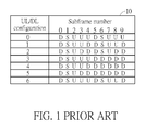
- Fig. 1 is a table 10 of the UL/DL configuration with subframes and corresponding directions.
- 7 UL/DL configurations are shown, wherein each of the UL/DL configurations indicates a set of directions for 10 subframes, respectively.
- U means that the subframe is a UL subframe where UL data is transmitted
- D means that the subframe is a DL subframe where DL data is transmitted
- S means that the subframe is a special subframe where control information and maybe data (according to the special subframe configuration) is transmitted.
- eNBs in the LTE/LTE-A system operating in the TDD mode may be configured with various UL/DL configurations.
- a DL subframe for an eNB may be UL subframes for neighboring eNBs of the eNB, when the eNB and the neighboring eNBs are configured with different UL/DL configurations.
- a UL subframe for the eNB may be DL subframes for the neighboring eNBs of the eNB.
- diverse measurement results may be obtained by the eNB or a UE in a coverage area of the eNB, when measurements of interferences are performed in different subframes.
- the diverse measurement results mainly come from that different combinations of subframe types of the eNB and the neighboring eNBs may occur in a single subframe.
- a combination may be that a subframe is DL (or UL) for all of the eNB and the neighboring eNBs.
- a combination may be that a subframe is DL (or UL) for the eNB and some of the neighboring eNBs, while the subframe is UL (or DL) for the other neighboring eNBs.
- Interference measurement in the TDD system becomes an important problem to be solved.
- the present invention therefore provides a method and related communication device for handling an interference measurement in the TDD system to solve the abovementioned problem.
- the claimed method of handling an interference measurement for a communication device in a time-division duplexing (TDD) system comprises receiving a signal; measuring an interference coming from at least one cell with at least one uplink/downlink (UL/DL) configuration in the TDD system in a subframe according to the signal, to obtain a measured interference; and generating a measurement result comprising the measured interference and information of the at least one UL/DL configuration of the at least one cell.
- TDD time-division duplexing
- Fig. 2 is a schematic diagram of a wireless communication system 20 according to an example of the present invention.
- the wireless communication system 20 is briefly composed of two base stations (BSs) BS1-BS2 and four user equipments (UEs) UE1-UE4.
- the wireless communication system 20 supports a time-division duplexing (TDD) mode, hereinafter the TDD system 20 for short. That is, the BSs BS1-BS2 and the UEs UE1-UE4 can communicate with each other by using uplink (UL) subframes and downlink (DL) subframes according to one or more UL/DL configurations.
- TDD time-division duplexing
- coverage areas of the BSs BS1-BS2 can be seen as two different cells C1-C2, e.g., partly overlapped cells or nonoverlapped cells.
- the UEs UE1-UE2 are in the cell C1 and the UEs UE3-UE4 are in the cell C2. That is, the cell C1 can be seen as a serving cell of the UEs UE1-UE2, and the cell C2 can be seen as a serving cell of the UEs UE3-UE4.
- a single BS may generate multiple cells.
- the UEs UE1 and UE2 may be in different cells controlled by the BS BS1.
- BSs BS1-BS2 and the UEs UE1-UE4 are simply utilized for illustrating the structure of the TDD system 20.
- the BSs BS1-BS2 and the UEs UE1-UE4 may support the 3rd Generation Partnership Project (3GPP) Rel-11 standard or later versions.
- 3GPP 3rd Generation Partnership Project
- a BS may be a Node-B (NB) in universal terrestrial radio access network (UTRAN) of a universal mobile telecommunications system (UMTS).
- UTRAN universal terrestrial radio access network
- UMTS universal mobile telecommunications system
- the BS may be an evolved NB (eNB) or a relay in an evolved UTRAN (E-UTRAN) of a long term evolution (LTE) system, a LTE-Advanced (LTE-A) system or an evolution of the LTE-A system.
- LTE long term evolution
- LTE-A LTE-Advanced
- a UE can be a mobile phone, a laptop, a tablet computer, an electronic book or a portable computer system but is not limited to these examples.
- a BS and a UE can be seen as a transmitter or a receiver according to a direction of transmission/reception, e.g., for an UL, the UE is the transmitter and the BS is the receiver, and for a DL, the BS is the transmitter and the UE is the receiver.
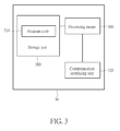
- Fig. 3 is a schematic diagram of a communication device 30 according to an example of the present invention.
- the communication device 30 can be a UE (e.g., the UE UE1, UE2, UE3 or UE4) or a BS (e.g., the BS BS1 or BS2) shown in Fig. 2 , but is not limited herein.
- the communication device 30 may include a processing means 300 such as a microprocessor or Application Specific Integrated Circuit (ASIC), a storage unit 310 and a communication interfacing unit 320.
- ASIC Application Specific Integrated Circuit
- the storage unit 310 may be any data storage device that can store a program code 314, accessed and executed by the processing means 300. Examples of the storage unit 310 include a subscriber identity module (SIM), read-only memory (ROM), flash memory, random-access memory (RAM), CD-ROM/DVD-ROM, magnetic tape, hard disk and optical data storage device.
- SIM subscriber identity module
- ROM read-only memory
- RAM random-access memory
- CD-ROM/DVD-ROM magnetic tape
- hard disk and optical data storage device optical data storage device.
- the communication interfacing unit 320 is preferably a transceiver and is used to transmit and receive signals (e.g., messages or packets) according to processing results of the processing means 300.
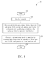
- Fig. 4 is a flowchart of a process 40 according to an example of the present invention. The process 40 is utilized in a communication device, for handling an interference measurement in a TDD system.
- the process 40 may be compiled into the program code 314 and includes the following steps: Step 400: Start. Step 402: Receive a signal. Step 404: Measure an interference coming from at least one cell in the TDD system with at least one UL/DL configuration in a subframe according to the signal, to obtain a measured interference. Step 406: Generate a measurement result comprising the measured interference and information of the at least one UL/DL configuration of the at least one cell. Step 408: End.
- the communication device measures an interference coming from (i.e., caused by) at least one cell in the TDD system with at least one UL/DL configuration in a subframe according to (e.g., by using) the signal, to obtain a measured interference, after receiving a signal. Then, the communication device generates a measurement result comprising the measured interference and information of the at least one UL/DL configuration of the at least one cell. In other words, the measurement result not only includes the measured interference but also includes the information of the at least one UL/DL configuration. The information can be used for determining a situation (i.e., scenario) in which the interference is measured.
- the measured interference can be exploited efficiently by the communication device and/or another communication device receiving the measurement result from the communication device, because the information of the at least one UL/DL configuration is also available in the measurement result. As a result, throughput of the communication device and/or another communication device is improved.
- Realization of the present invention is not limited to the example of the process 40.
- Fig. 5 is a schematic diagram of a TDD system 50 according to an example of the present invention.
- the UEs UE1-UE4 and the BSs BS1 and BS2 operate according to various UL/DL configurations in a subframe.
- the interference mentioned in the process 40 may be a summation of interferences caused by the BS BS1 and the UEs UE3-UE4 in the present example.
- the interference may include an interference 500 caused by a transmission 502 from the BS BS1 to the UE UE2, an interference 510 caused by a transmission 512 from the UE UE3 to the BS BS2, and an interference 520 caused by a transmission 522 from the UE UE4 to the BS BS2.
- the subframe can be the subframe 3
- the UL/DL configurations of the BS BS1 and the UEs UE3-UE4 can be the UL/DL configurations 2, 3 and 4, respectively, as shown in Fig. 1 .
- the UE UE1 obtains a measured interference, after measuring the summation of the interferences 500, 510 and 520 by using a received signal. Then, the UE UE1 generates a measurement result including the measured interference and information of the UL/DL configurations of the BS BS1 and the UEs UE3-UE4.
- the subframe is a DL subframe for the cell C1 (i.e., the BS BS1), and a UL subframe for the cell C2 (i.e., the UEs UE3 and UE4).
- the interference includes both the DL interference (i.e., the interference 500) and the UL interference (i.e., the interferences 510 and 520).
- the interference 500 can be seen as an intra-cell interference with respect to the UE UE1, since the interference 500 comes from the cell C1 where the UE UE1 locates.
- the interferences 510 and 520 can be seen as an inter-cell interference with respect to the UE UE1, since the interferences 510 and 520 come from the cell C2.
- Fig. 6 is a schematic diagram of a TDD system 60 according to an example of the present invention.
- the UE UE1 be the communication device mentioned in the process 40 and let the cells C1-C2 be the at least one cell mentioned in the process 40.
- the UEs UE1-UE4 and the BSs BS1 and BS2 operate according to various UL/DL configurations in a subframe.
- the interference mentioned in the process 40 may be a summation of interferences caused by the BSs BS1-BS2 in the present example.
- the interference may include an interference 600 caused by a transmission 602 from the BS BS1 to the UE UE2, an interference 610 caused by a transmission 612 from the BS BS2 to the UE UE3, and an interference 620 caused by a transmission 622 from the BS BS2 to the UE UE4.
- the subframe can be the subframe 5
- the UL/DL configurations of the BSs BS1-BS2 can be the UL/DL configurations 1 and 2, respectively, as shown in Fig. 1 .
- the UE UE1 obtains a measured interference, after measuring the summation of the interferences 600, 610 and 620 by using a received signal. Then, the UE UE1 generates a measurement result including the measured interference and information of the UL/DL configurations of the BSs BS1-BS2.
- the subframe is a DL subframe for the cells C1-C2 (i.e., the BSs BS1-BS2).
- the interference includes only the DL interferences (i.e., the interference 600, 610 and 620).
- the interference 600 can be seen as an intra-cell interference with respect to the UE UE1, since the interference 600 comes from the cell C1 where the UE UE1 locates.
- the interferences 610 and 620 can be seen as an inter-cell interference with respect to the UE UE1, since the interferences 610 and 620 come from the cell C2.
- Fig. 7 is a schematic diagram of a TDD system 70 according to an example of the present invention.
- the UE UE1 be the communication device mentioned in the process 40 and let the cells C1-C2 be the at least one cell mentioned in the process 40.
- the UEs UE1-UE4 and the BSs BS1 and BS2 operate according to various UL/DL configurations in a subframe.
- the interference mentioned in the process 40 may be a summation of interferences caused by the UEs UE2-UE4 in the present example.
- the interference may include an interference 700 caused by a transmission 702 from the UE UE2 to the BS BS1, an interference 710 caused by a transmission 712 from the UE UE3 to the BS BS2, and an interference 720 caused by a transmission 722 from the UE UE4 to the BS BS2.
- the subframe can be the subframe 6, and the UL/DL configurations of the UEs UE2-UE4 can be the UL/DL configurations 0, 1 and 2, respectively, as shown in Fig. 1 .
- the UE UE1 obtains a measured interference, after measuring the summation of the interferences 700, 710 and 720 by using a received signal. Then, the UE UE1 generates a measurement result including the measured interference and information of the UL/DL configurations of the UEs UE2-UE4.
- the subframe is a UL subframe for the cells C1-C2 (i.e., the UEs UE2-UE4).
- the interference includes only the UL interferences (i.e., the interference 700, 710 and 720).
- the interference 700 can be seen as an intra-cell interference with respect to the UE UE1, since the interference 700 comes from the cell C1 where the UE UE1 locates.
- the interferences 710 and 720 can be seen as an inter-cell interference with respect to the UE UE1, since the interferences 710 and 720 come from the cell C2.
- a method according to which a communication device measures an interference is not limited herein.
- the communication device may measure the interference according to a measurement configuration including a resource via which the interference is measured and/or an indicator which indicates the communication device to measure the interference.
- the resource may be a time and/or a frequency band at which the interference is to be measured.
- the indicator may be an identity of the communication device, to notify the communication device to measure the interference.
- the measurement configuration may include multiple resources and multiple indicators which indicate multiple communication devices to measure the interference.
- the communication device may be in one of at least one cell, when the interference comes from the at least one cell. That is, part of the interference comes from a serving cell of the communication device.
- the communication device may not be in one of the at least one cell. That is, the interference completely comes from neighboring cells.
- the information of the at least one cell mentioned in the process 40 may include an indicator (e.g., scheme index) indicates a situation in which the measured interference is obtained according to the at least one UL/DL configuration.
- the situation may include at least one subframe type of the subframe of at least one UL/DL configuration of the at least one cell.
- the information may further include attributes such as a role (e.g., UE, BS, etc.) of the communication device measuring the interference.
- the role may be a transmitter, a receiver, a measure-only device.
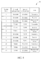
- Fig. 8 is a table 80 of scheme indices with corresponding subframe types and roles of a communication device according to an example of the present invention. As shown in Fig. 8 , each scheme index indicates a specific combination of intra-cell subframe type, inter-cell subframe type and the role of the communication device.
- Fig. 9 is a table 90 of scheme indices with corresponding subframe types of a communication device according to an example of the present invention. Different from Fig. 8 , each scheme index indicates a specific combination of intra-cell subframe type and inter-cell subframe type of the communication device in Fig. 9 . In addition, more subframe types are introduced in Fig. 9 , such as a special subframe shown in Fig. 1 and a blank subframe wherein no transmission/reception is performed. Thus, the communication device obtaining the scheme index can determining the situation in which the interference is measured.
- the UE measures the interference in the above examples.
- a BS may measure the interference in another example.
- the communication device e.g., the communication device in the process 40
- the communication device e.g., the communication device in the process 40
- the measured interference may include any quality metric such as a carrier to interference ratio, a carrier to interference plus noise ratio, an interference over thermal noise ratio, a bit error rate/frame error rate (e.g., in a data session), and is not limited herein.
- the signal used for measuring the interference is not limited herein.
- the signal may be a reference signal which is used for estimating one or more system parameters and/or performing one or more measurements.
- the signal may be a data packet. That is, the communication device measures the interference during regular communications, and the reference signal may not be needed. The above situations may happen when the communication device is in an active mode (e.g., connected mode).
- the communication device may measure the interference by using a background traffic, when the communication device is in an inactive mode (e.g., idle mode).
- an operation performed by the communication device on a measurement result after obtaining the measurement result is not limited herein.
- the communication device may communicate with another communication device in the TDD system according to the measurement result. That is, the communication device uses the measurement result itself.
- the communication device may adjust its transmission power according to the measurement result.
- the communication device may transmit the measurement result to another communication device in the TDD system. That is, the communication device shares the measurement result with another communication device, such that another communication device can use the measurement result.
- the communication device can be a UE or a BS.
- another communication device can be a UE or a BS. That is, the sharing of the measurement result can occur between the UE/the BS and the UE/the BS.
- the abovementioned steps of the processes including suggested steps can be realized by means that could be a hardware, a firmware known as a combination of a hardware device and computer instructions and data that reside as read-only software on the hardware device, or an electronic system.
- hardware can include analog, digital and mixed circuits known as microcircuit, microchip, or silicon chip.
- the electronic system can include a system on chip (SOC), system in package (SiP), a computer on module (COM), and the communication device 30.
- SOC system on chip
- SiP system in package
- COM computer on module
- the present invention provides a method for handling an interference measurement in the TDD system.
- a communication device can use a measured interference efficiently according to information of one or more UL/DL configurations related to the measured interference. As a result, throughput of the communication device is improved.
Landscapes
- Engineering & Computer Science (AREA)
- Signal Processing (AREA)
- Computer Networks & Wireless Communication (AREA)
- Mobile Radio Communication Systems (AREA)
Abstract
Description
- The present invention relates to a method of handling an interference measurement in a time-division duplexing (TDD) system and related communication device.
- A long-term evolution (LTE) system supporting the 3rd Generation Partnership Project (3GPP) Rel-8 standard and/or the 3GPP Rel-9 standard are developed by the 3GPP as a successor of the universal mobile telecommunications system (UMTS), for further enhancing performance of the UMTS to satisfy increasing needs of users. The LTE system includes a new radio interface and a new radio network architecture that provides a high data rate, low latency, packet optimization, and improved system capacity and coverage. In the LTE system, a radio access network known as an evolved universal terrestrial radio access network (E-UTRAN) includes multiple evolved Node-Bs (eNBs) for communicating with multiple user equipments (UEs), and for communicating with a core network including a mobility management entity (MME), a serving gateway, etc., for Non-Access Stratum (NAS) control.
- A LTE-advanced (LTE-A) system, as its name implies, is an evolution of the LTE system. The LTE-A system targets faster switching between power states, improves performance at the coverage edge of an eNB, and includes advanced techniques, such as carrier aggregation (CA), coordinated multipoint (CoMP) transmission/reception, UL multiple-input multiple-output (MIMO), etc. For a UE and an eNB to communicate with each other in the LTE-A system, the UE and the eNB must support standards developed for the LTE-A system, such as the 3GPP Rel-10 standard or later versions.
- Different from the LTE/LTE-A system operating in a frequency-division duplexing (FDD) mode, directions of subframes of a frequency band in the LTE/LTE-A system operating in a time-division duplexing (TDD) mode may be different. That is, the subframes in the same frequency band are divided into uplink (UL) subframes, downlink (DL) subframes and special subframes according to the UL/DL configuration specified in the 3GPP standard.
-
Fig. 1 is a table 10 of the UL/DL configuration with subframes and corresponding directions. InFig. 1 ,7 UL/DL configurations are shown, wherein each of the UL/DL configurations indicates a set of directions for 10 subframes, respectively. In detail, "U" means that the subframe is a UL subframe where UL data is transmitted, and "D" means that the subframe is a DL subframe where DL data is transmitted. "S" means that the subframe is a special subframe where control information and maybe data (according to the special subframe configuration) is transmitted. - However, eNBs in the LTE/LTE-A system operating in the TDD mode (hereinafter, the TDD system, for short) may be configured with various UL/DL configurations. In other words, a DL subframe for an eNB may be UL subframes for neighboring eNBs of the eNB, when the eNB and the neighboring eNBs are configured with different UL/DL configurations. Alternatively, a UL subframe for the eNB may be DL subframes for the neighboring eNBs of the eNB. In this situation, diverse measurement results may be obtained by the eNB or a UE in a coverage area of the eNB, when measurements of interferences are performed in different subframes. The diverse measurement results mainly come from that different combinations of subframe types of the eNB and the neighboring eNBs may occur in a single subframe. For example, a combination may be that a subframe is DL (or UL) for all of the eNB and the neighboring eNBs. In another example, a combination may be that a subframe is DL (or UL) for the eNB and some of the neighboring eNBs, while the subframe is UL (or DL) for the other neighboring eNBs. Thus, it is difficult for the eNB and the UE to utilize the diverse measurement results efficiently. Interference measurement in the TDD system becomes an important problem to be solved.
- The present invention therefore provides a method and related communication device for handling an interference measurement in the TDD system to solve the abovementioned problem.
- This is achieved by a method and a communication device for handling the interference measurement according to the independent claims here below. The dependent claims pertain to corresponding further developments and improvements.
- As will be seen more clearly from the detailed description following below, the claimed method of handling an interference measurement for a communication device in a time-division duplexing (TDD) system comprises receiving a signal; measuring an interference coming from at least one cell with at least one uplink/downlink (UL/DL) configuration in the TDD system in a subframe according to the signal, to obtain a measured interference; and generating a measurement result comprising the measured interference and information of the at least one UL/DL configuration of the at least one cell.
-
-
Fig. 1 is a table of the UL/DL configuration with subframes and corresponding directions. -
Fig. 2 is a schematic diagram of a wireless communication system according to an example of the present invention. -
Fig. 3 is a schematic diagram of a communication device according to an example of the present invention. -
Fig. 4 is a flowchart of a process according to an example of the present invention. -
Fig. 5 is a schematic diagram of a schematic diagram of a TDD system according to an example of the present invention. -
Fig. 6 is a schematic diagram of a schematic diagram of a TDD system according to an example of the present invention. -
Fig. 7 is a schematic diagram of a schematic diagram of a TDD system according to an example of the present invention. -
Fig. 8 is a table 80 of scheme indices with corresponding subframe types and roles of a communication device according to an example of the present invention. -
Fig. 9 is a table of scheme indices with corresponding subframe types according to an example of the present invention. -
Fig. 2 is a schematic diagram of awireless communication system 20 according to an example of the present invention. Thewireless communication system 20 is briefly composed of two base stations (BSs) BS1-BS2 and four user equipments (UEs) UE1-UE4. Thewireless communication system 20 supports a time-division duplexing (TDD) mode, hereinafter theTDD system 20 for short. That is, the BSs BS1-BS2 and the UEs UE1-UE4 can communicate with each other by using uplink (UL) subframes and downlink (DL) subframes according to one or more UL/DL configurations. - It should be noted, in one example, coverage areas of the BSs BS1-BS2 can be seen as two different cells C1-C2, e.g., partly overlapped cells or nonoverlapped cells. As shown in
Fig. 2 , the UEs UE1-UE2 are in the cell C1 and the UEs UE3-UE4 are in the cell C2. That is, the cell C1 can be seen as a serving cell of the UEs UE1-UE2, and the cell C2 can be seen as a serving cell of the UEs UE3-UE4. In addition, a single BS may generate multiple cells. For example, the UEs UE1 and UE2 may be in different cells controlled by the BS BS1. - In
Fig. 2 , the BSs BS1-BS2 and the UEs UE1-UE4 are simply utilized for illustrating the structure of theTDD system 20. For example, the BSs BS1-BS2 and the UEs UE1-UE4 may support the 3rd Generation Partnership Project (3GPP) Rel-11 standard or later versions. In detail, a BS may be a Node-B (NB) in universal terrestrial radio access network (UTRAN) of a universal mobile telecommunications system (UMTS). In another example, the BS may be an evolved NB (eNB) or a relay in an evolved UTRAN (E-UTRAN) of a long term evolution (LTE) system, a LTE-Advanced (LTE-A) system or an evolution of the LTE-A system. A UE can be a mobile phone, a laptop, a tablet computer, an electronic book or a portable computer system but is not limited to these examples. In addition, a BS and a UE can be seen as a transmitter or a receiver according to a direction of transmission/reception, e.g., for an UL, the UE is the transmitter and the BS is the receiver, and for a DL, the BS is the transmitter and the UE is the receiver. More specifically, for the BS, the direction of the transmission is DL, and the direction of the reception is UL. For the UE, the direction of the transmission is UL, and the direction of the reception is DL.
Fig. 3 is a schematic diagram of acommunication device 30 according to an example of the present invention. Thecommunication device 30 can be a UE (e.g., the UE UE1, UE2, UE3 or UE4) or a BS (e.g., the BS BS1 or BS2) shown inFig. 2 , but is not limited herein. Thecommunication device 30 may include a processing means 300 such as a microprocessor or Application Specific Integrated Circuit (ASIC), astorage unit 310 and acommunication interfacing unit 320. Thestorage unit 310 may be any data storage device that can store aprogram code 314, accessed and executed by the processing means 300. Examples of thestorage unit 310 include a subscriber identity module (SIM), read-only memory (ROM), flash memory, random-access memory (RAM), CD-ROM/DVD-ROM, magnetic tape, hard disk and optical data storage device. Thecommunication interfacing unit 320 is preferably a transceiver and is used to transmit and receive signals (e.g., messages or packets) according to processing results of the processing means 300.
Fig. 4 is a flowchart of aprocess 40 according to an example of the present invention. Theprocess 40 is utilized in a communication device, for handling an interference measurement in a TDD system. Theprocess 40 may be compiled into theprogram code 314 and includes the following steps:Step 400: Start. Step 402: Receive a signal. Step 404: Measure an interference coming from at least one cell in the TDD system with at least one UL/DL configuration in a subframe according to the signal, to obtain a measured interference. Step 406: Generate a measurement result comprising the measured interference and information of the at least one UL/DL configuration of the at least one cell. Step 408: End. - According to the
process 40, the communication device measures an interference coming from (i.e., caused by) at least one cell in the TDD system with at least one UL/DL configuration in a subframe according to (e.g., by using) the signal, to obtain a measured interference, after receiving a signal. Then, the communication device generates a measurement result comprising the measured interference and information of the at least one UL/DL configuration of the at least one cell. In other words, the measurement result not only includes the measured interference but also includes the information of the at least one UL/DL configuration. The information can be used for determining a situation (i.e., scenario) in which the interference is measured. Thus, the measured interference can be exploited efficiently by the communication device and/or another communication device receiving the measurement result from the communication device, because the information of the at least one UL/DL configuration is also available in the measurement result. As a result, throughput of the communication device and/or another communication device is improved. - Realization of the present invention is not limited to the example of the
process 40. -
Fig. 5 is a schematic diagram of aTDD system 50 according to an example of the present invention. Let the UE UE1 be the communication device mentioned in theprocess 40 and let the cells C1-C2 be the at least one cell mentioned in theprocess 40. The UEs UE1-UE4 and the BSs BS1 and BS2 operate according to various UL/DL configurations in a subframe. The interference mentioned in theprocess 40 may be a summation of interferences caused by the BS BS1 and the UEs UE3-UE4 in the present example. In detail, the interference may include aninterference 500 caused by atransmission 502 from the BS BS1 to the UE UE2, aninterference 510 caused by atransmission 512 from the UE UE3 to the BS BS2, and aninterference 520 caused by atransmission 522 from the UE UE4 to the BS BS2. As an example, the subframe can be thesubframe 3, and the UL/DL configurations of the BS BS1 and the UEs UE3-UE4 can be the UL/DL configurations Fig. 1 . According to theprocess 40, the UE UE1 obtains a measured interference, after measuring the summation of theinterferences - As can be seen, the subframe is a DL subframe for the cell C1 (i.e., the BS BS1), and a UL subframe for the cell C2 (i.e., the UEs UE3 and UE4). The interference includes both the DL interference (i.e., the interference 500) and the UL interference (i.e., the
interferences 510 and 520). In addition, theinterference 500 can be seen as an intra-cell interference with respect to the UE UE1, since theinterference 500 comes from the cell C1 where the UE UE1 locates. Oppositely, theinterferences interferences -
Fig. 6 is a schematic diagram of aTDD system 60 according to an example of the present invention. Similarly, let the UE UE1 be the communication device mentioned in theprocess 40 and let the cells C1-C2 be the at least one cell mentioned in theprocess 40. The UEs UE1-UE4 and the BSs BS1 and BS2 operate according to various UL/DL configurations in a subframe. The interference mentioned in theprocess 40 may be a summation of interferences caused by the BSs BS1-BS2 in the present example. In detail, the interference may include aninterference 600 caused by atransmission 602 from the BS BS1 to the UE UE2, aninterference 610 caused by atransmission 612 from the BS BS2 to the UE UE3, and aninterference 620 caused by atransmission 622 from the BS BS2 to the UE UE4. As an example, the subframe can be thesubframe 5, and the UL/DL configurations of the BSs BS1-BS2 can be the UL/DL configurations Fig. 1 . According to theprocess 40, the UE UE1 obtains a measured interference, after measuring the summation of theinterferences - As can be seen, the subframe is a DL subframe for the cells C1-C2 (i.e., the BSs BS1-BS2). The interference includes only the DL interferences (i.e., the
interference interference 600 can be seen as an intra-cell interference with respect to the UE UE1, since theinterference 600 comes from the cell C1 where the UE UE1 locates. Oppositely, theinterferences interferences -
Fig. 7 is a schematic diagram of aTDD system 70 according to an example of the present invention. Similarly, let the UE UE1 be the communication device mentioned in theprocess 40 and let the cells C1-C2 be the at least one cell mentioned in theprocess 40. The UEs UE1-UE4 and the BSs BS1 and BS2 operate according to various UL/DL configurations in a subframe. The interference mentioned in theprocess 40 may be a summation of interferences caused by the UEs UE2-UE4 in the present example. In detail, the interference may include aninterference 700 caused by atransmission 702 from the UE UE2 to the BS BS1, aninterference 710 caused by atransmission 712 from the UE UE3 to the BS BS2, and aninterference 720 caused by atransmission 722 from the UE UE4 to the BS BS2. As an example, the subframe can be thesubframe 6, and the UL/DL configurations of the UEs UE2-UE4 can be the UL/DL configurations Fig. 1 . According to theprocess 40, the UE UE1 obtains a measured interference, after measuring the summation of theinterferences - As can be seen, the subframe is a UL subframe for the cells C1-C2 (i.e., the UEs UE2-UE4). The interference includes only the UL interferences (i.e., the
interference interference 700 can be seen as an intra-cell interference with respect to the UE UE1, since theinterference 700 comes from the cell C1 where the UE UE1 locates. Oppositely, theinterferences interferences - It should be noted that, a method according to which a communication device (e.g., the communication device in the
process 40 or the UE UE1 in the above descriptions) measures an interference is not limited herein. For example, the communication device may measure the interference according to a measurement configuration including a resource via which the interference is measured and/or an indicator which indicates the communication device to measure the interference. The resource may be a time and/or a frequency band at which the interference is to be measured. The indicator may be an identity of the communication device, to notify the communication device to measure the interference. In addition, the measurement configuration may include multiple resources and multiple indicators which indicate multiple communication devices to measure the interference. - In addition, the communication device may be in one of at least one cell, when the interference comes from the at least one cell. That is, part of the interference comes from a serving cell of the communication device. In another example, the communication device may not be in one of the at least one cell. That is, the interference completely comes from neighboring cells.
- In addition, the information of the at least one cell mentioned in the
process 40 may include an indicator (e.g., scheme index) indicates a situation in which the measured interference is obtained according to the at least one UL/DL configuration. For example, the situation may include at least one subframe type of the subframe of at least one UL/DL configuration of the at least one cell. In another example, the information may further include attributes such as a role (e.g., UE, BS, etc.) of the communication device measuring the interference. The role may be a transmitter, a receiver, a measure-only device. -
Fig. 8 is a table 80 of scheme indices with corresponding subframe types and roles of a communication device according to an example of the present invention. As shown inFig. 8 , each scheme index indicates a specific combination of intra-cell subframe type, inter-cell subframe type and the role of the communication device. -
Fig. 9 is a table 90 of scheme indices with corresponding subframe types of a communication device according to an example of the present invention. Different fromFig. 8 , each scheme index indicates a specific combination of intra-cell subframe type and inter-cell subframe type of the communication device inFig. 9 . In addition, more subframe types are introduced inFig. 9 , such as a special subframe shown inFig. 1 and a blank subframe wherein no transmission/reception is performed. Thus, the communication device obtaining the scheme index can determining the situation in which the interference is measured. - Note that the UE measures the interference in the above examples. This is not a limitation, and a BS may measure the interference in another example. That is, the communication device (e.g., the communication device in the process 40) mentioned above may be a UE or a BS. In addition, the measured interference may include any quality metric such as a carrier to interference ratio, a carrier to interference plus noise ratio, an interference over thermal noise ratio, a bit error rate/frame error rate (e.g., in a data session), and is not limited herein.
- On the other hand, the signal used for measuring the interference is not limited herein. For example, the signal may be a reference signal which is used for estimating one or more system parameters and/or performing one or more measurements. In another example, the signal may be a data packet. That is, the communication device measures the interference during regular communications, and the reference signal may not be needed. The above situations may happen when the communication device is in an active mode (e.g., connected mode). In another example, the communication device may measure the interference by using a background traffic, when the communication device is in an inactive mode (e.g., idle mode).
- It should be noted that, an operation performed by the communication device on a measurement result after obtaining the measurement result is not limited herein. For example, the communication device may communicate with another communication device in the TDD system according to the measurement result. That is, the communication device uses the measurement result itself. For example, the communication device may adjust its transmission power according to the measurement result. In another example, the communication device may transmit the measurement result to another communication device in the TDD system. That is, the communication device shares the measurement result with another communication device, such that another communication device can use the measurement result. Note that the communication device can be a UE or a BS. Similarly, another communication device can be a UE or a BS. That is, the sharing of the measurement result can occur between the UE/the BS and the UE/the BS.
- Those skilled in the art should readily make combinations, modifications and/or alterations on the abovementioned description and examples. The abovementioned steps of the processes including suggested steps can be realized by means that could be a hardware, a firmware known as a combination of a hardware device and computer instructions and data that reside as read-only software on the hardware device, or an electronic system. Examples of hardware can include analog, digital and mixed circuits known as microcircuit, microchip, or silicon chip. Examples of the electronic system can include a system on chip (SOC), system in package (SiP), a computer on module (COM), and the
communication device 30. - To sum up, the present invention provides a method for handling an interference measurement in the TDD system. A communication device can use a measured interference efficiently according to information of one or more UL/DL configurations related to the measured interference. As a result, throughput of the communication device is improved.
Claims (14)
- A method of handling an interference measurement for a communication device in a time-division duplexing (TDD) system, characterized by the method comprising the steps of:receiving a signal (402);measuring an interference coming from at least one cell with at least one uplink/downlink (UL/DL) configuration in the TDD system in a subframe according to the signal, to obtain a measured interference (404); andgenerating a measurement result comprising the measured interference and information of the at least one UL/DL configuration of the at least one cell (406).
- The method of claim 1, characterized in that the communication device measures the interference according to a measurement configuration comprising a resource via which the interference is measured and/or an indicator which indicates the communication device to measure the interference.
- The method of claim 1 or 2, characterized in that the communication device is in one of the at least one cell.
- The method of any of claims 1-3, characterized in that the information comprises an indicator which indicates a situation in which the measured interference is obtained according to the at least one UL/DL configuration.
- The method of claim 4, characterized in that the situation comprises at least one subframe type of the subframe of the at least one UL/DL configuration.
- The method of any of claims 1-5, characterized in that the signal is a reference signal.
- The method of any of claims 1-5, characterized in that the signal is a data packet.
- The method of any of claims 1-7, characterized in that the communication device is in an active mode.
- The method of any of claims 1-7, characterized in that the communication device is in an inactive mode.
- The method of any of claims 1-9, further comprising:communicating with an another communication device in the TDD system according to the measurement result.
- The method of any of claims 1-10, further comprising:transmitting the measurement result to another communication device in the TDD system.
- The method of any of claims 1-11, characterized in that the measured interference comprises a carrier to interference ratio, a carrier to interference plus noise ratio, an interference over thermal noise ratio, a bit error rate and/or a frame error rate.
- A communication device capable of handling an interference measurement according to any combination of claims 1-12.
- A communication device (30) in a time-division duplexing (TDD) system for handling an interference measurement, characterized by the communication device comprising:a processing means (300) for executing a program (314); anda storage unit (310) coupled to the processing means for storing the program; wherein the program instructs the processing means to perform the following steps:receiving a signal (402);measuring an interference coming from at least one cell with at least one uplink/downlink (UL/DL) configuration in the TDD system in a subframe according to the signal, to obtain a measured interference (404); andgenerating a measurement result comprising the measured interference and information of the at least one UL/DL configuration of the at least one cell (406).
Applications Claiming Priority (2)
| Application Number | Priority Date | Filing Date | Title |
|---|---|---|---|
| US201361760181P | 2013-02-04 | 2013-02-04 | |
| US14/164,277 US9699675B2 (en) | 2013-02-04 | 2014-01-27 | Method of handling interference measurement in TDD system and related communication device |
Publications (2)
| Publication Number | Publication Date |
|---|---|
| EP2763456A1 true EP2763456A1 (en) | 2014-08-06 |
| EP2763456B1 EP2763456B1 (en) | 2019-02-27 |
Family
ID=50031148
Family Applications (1)
| Application Number | Title | Priority Date | Filing Date |
|---|---|---|---|
| EP14152820.8A Active EP2763456B1 (en) | 2013-02-04 | 2014-01-28 | Method of Handling Interference Measurement in TDD System and Related Communication Device |
Country Status (4)
| Country | Link |
|---|---|
| US (1) | US9699675B2 (en) |
| EP (1) | EP2763456B1 (en) |
| CN (1) | CN103974283B (en) |
| TW (1) | TWI523552B (en) |
Cited By (1)
| Publication number | Priority date | Publication date | Assignee | Title |
|---|---|---|---|---|
| EP3742788A4 (en) * | 2018-02-09 | 2021-03-31 | Huawei Technologies Co., Ltd. | MEASUREMENT REPORT TRANSMISSION PROCESS, COMMUNICATION DEVICE AND SYSTEM |
Families Citing this family (1)
| Publication number | Priority date | Publication date | Assignee | Title |
|---|---|---|---|---|
| WO2019136700A1 (en) * | 2018-01-12 | 2019-07-18 | 海能达通信股份有限公司 | Interference processing method, interference processing apparatus and computer storage medium |
Citations (3)
| Publication number | Priority date | Publication date | Assignee | Title |
|---|---|---|---|---|
| EP2221985A2 (en) * | 2005-08-22 | 2010-08-25 | Sony Corporation | Uplink resource allocation to control intercell interference in a wireless communication system |
| WO2012115811A1 (en) * | 2011-02-21 | 2012-08-30 | Motorola Mobility Llc | Method and apparatus for reference signal processing in an orthogonal frequency division multiplexing communication system |
| US20120236736A1 (en) * | 2011-03-18 | 2012-09-20 | Motorola Mobility, Inc. | Method and Apparatus for Multi-Radio Coexistence with a System on an Adjacent Frequency Band Having a Time-Dependent Configuration |
Family Cites Families (13)
| Publication number | Priority date | Publication date | Assignee | Title |
|---|---|---|---|---|
| US6167031A (en) * | 1997-08-29 | 2000-12-26 | Telefonaktiebolaget Lm Ericsson (Publ) | Method for selecting a combination of modulation and channel coding schemes in a digital communication system |
| CN101472305B (en) * | 2007-12-26 | 2012-01-25 | 电信科学技术研究院 | Method, system and device for implementing district switch |
| US8027255B2 (en) * | 2008-09-30 | 2011-09-27 | Alcatel Lucent | Method and apparatus for prioritizing packets for use in managing packets in radio access networks |
| US8611331B2 (en) * | 2009-02-27 | 2013-12-17 | Qualcomm Incorporated | Time division duplexing (TDD) configuration for access point base stations |
| WO2011073737A1 (en) * | 2009-12-18 | 2011-06-23 | Nokia Corporation | Method and apparatus for providing a communication scheme with reduced feedback delay |
| WO2011116815A1 (en) * | 2010-03-23 | 2011-09-29 | Nokia Siemens Networks Oy | Resource allocation for direct terminal-to-terminal communication in a cellular system |
| US8681648B2 (en) * | 2010-03-24 | 2014-03-25 | Telcordia Technologies, Inc. | Mobility policy updates for mobile devices |
| US9173121B2 (en) * | 2010-11-01 | 2015-10-27 | Qualcomm Incorporated | Method and apparatus for restricted measuring in a wireless network |
| US8670330B2 (en) * | 2011-01-26 | 2014-03-11 | Qualcomm Incorporated | Methods and apparatus to perform reference signal measurements in a TDD-LTE system from a TD-SCDMA system |
| EP2719217A4 (en) * | 2011-06-09 | 2015-09-02 | Broadcom Corp | Interference control in time division duplex communication |
| TW201322681A (en) * | 2011-09-26 | 2013-06-01 | Innovative Sonic Corp | Method and apparatus for processing Channel State Information in a wireless communication system |
| CN103188797A (en) * | 2011-12-28 | 2013-07-03 | 北京三星通信技术研究有限公司 | Method for changing up and down TDD configuration |
| CN108111290B (en) * | 2012-01-20 | 2021-02-02 | 北京三星通信技术研究有限公司 | PUSCH transmission method and equipment |
-
2014
- 2014-01-27 US US14/164,277 patent/US9699675B2/en active Active
- 2014-01-28 TW TW103103236A patent/TWI523552B/en active
- 2014-01-28 EP EP14152820.8A patent/EP2763456B1/en active Active
- 2014-01-29 CN CN201410046213.8A patent/CN103974283B/en active Active
Patent Citations (3)
| Publication number | Priority date | Publication date | Assignee | Title |
|---|---|---|---|---|
| EP2221985A2 (en) * | 2005-08-22 | 2010-08-25 | Sony Corporation | Uplink resource allocation to control intercell interference in a wireless communication system |
| WO2012115811A1 (en) * | 2011-02-21 | 2012-08-30 | Motorola Mobility Llc | Method and apparatus for reference signal processing in an orthogonal frequency division multiplexing communication system |
| US20120236736A1 (en) * | 2011-03-18 | 2012-09-20 | Motorola Mobility, Inc. | Method and Apparatus for Multi-Radio Coexistence with a System on an Adjacent Frequency Band Having a Time-Dependent Configuration |
Non-Patent Citations (2)
| Title |
|---|
| CATT: "Interference mitigation schemes for TDD eIMTA", vol. RAN WG1, no. St. Julian; 20130128 - 20130201, 18 January 2013 (2013-01-18), XP050663295, Retrieved from the Internet <URL:http://www.3gpp.org/ftp/tsg_ran/WG1_RL1/TSGR1_72/Docs/> [retrieved on 20130118] * |
| ITRI: "Evaluation of eIMTA with dual CSI feedbacks", vol. RAN WG1, no. St Julian; 20130128 - 20130201, 18 January 2013 (2013-01-18), XP050663332, Retrieved from the Internet <URL:http://www.3gpp.org/ftp/tsg_ran/WG1_RL1/TSGR1_72/Docs/> [retrieved on 20130118] * |
Cited By (2)
| Publication number | Priority date | Publication date | Assignee | Title |
|---|---|---|---|---|
| EP3742788A4 (en) * | 2018-02-09 | 2021-03-31 | Huawei Technologies Co., Ltd. | MEASUREMENT REPORT TRANSMISSION PROCESS, COMMUNICATION DEVICE AND SYSTEM |
| US11470493B2 (en) | 2018-02-09 | 2022-10-11 | Huawei Technologies Co., Ltd. | Method for sending measurement report, communications apparatus, and system |
Also Published As
| Publication number | Publication date |
|---|---|
| CN103974283B (en) | 2018-06-05 |
| TW201433191A (en) | 2014-08-16 |
| CN103974283A (en) | 2014-08-06 |
| TWI523552B (en) | 2016-02-21 |
| US9699675B2 (en) | 2017-07-04 |
| EP2763456B1 (en) | 2019-02-27 |
| US20140219121A1 (en) | 2014-08-07 |
Similar Documents
| Publication | Publication Date | Title |
|---|---|---|
| EP3682683B1 (en) | Beam indication for uplink power control | |
| US9276646B2 (en) | Method of managing cooperating set for coordinated multiple point transmission and reception and related communication device | |
| US20150146585A1 (en) | Apparatuses and method using enhanced control channel information for tdd-fdd carrier aggregation | |
| US10863398B2 (en) | Device and method of handling a handover | |
| CN112368969A (en) | Device-to-device (D2D) channel measurement techniques | |
| JP5781016B2 (en) | Wireless base station, wireless communication system, and wireless communication method | |
| CN110603751B (en) | Communication scheme for small cyclic delay diversity reference signals | |
| US9774427B2 (en) | Method of handling uplink/downlink configurations for time-division duplexing system and related communication device | |
| CN114270787B (en) | Method and device for complete configuration switching technology | |
| US9717013B2 (en) | Device and method of handling measurement configuration | |
| US20170202021A1 (en) | Device and Method of Handling Transmission/Reception for Serving Cell | |
| EP3143715A1 (en) | Method and apparatus for transmitting and/or receiving reference signals | |
| KR20200090229A (en) | Signaling of radio transmission mapping types | |
| EP3381135B1 (en) | Beamforming and user equipment grouping | |
| US9722719B2 (en) | Method of handling HARQ resource in TDD system and related communication device | |
| EP2723000A1 (en) | Method of handling beamforming feedback in a wireless communication system and related communication device | |
| US11159290B2 (en) | Device and method for handling a sounding reference signal transmission | |
| US9867061B2 (en) | Method of handling measurement pattern for TDD system and related communication device | |
| CN112584443A (en) | Secondary cell link recovery request transmission | |
| US20140254411A1 (en) | Method of Handling Selections of Base Stations Related Communication Device | |
| US9699675B2 (en) | Method of handling interference measurement in TDD system and related communication device | |
| US9398541B2 (en) | Communication device for handling uplink power control | |
| CN112806066B (en) | System and method for communication using auxiliary uplinks | |
| WO2019246136A1 (en) | Device-to-device (d2d) channel measurement techniques |
Legal Events
| Date | Code | Title | Description |
|---|---|---|---|
| PUAI | Public reference made under article 153(3) epc to a published international application that has entered the european phase |
Free format text: ORIGINAL CODE: 0009012 |
|
| 17P | Request for examination filed |
Effective date: 20140128 |
|
| AK | Designated contracting states |
Kind code of ref document: A1 Designated state(s): AL AT BE BG CH CY CZ DE DK EE ES FI FR GB GR HR HU IE IS IT LI LT LU LV MC MK MT NL NO PL PT RO RS SE SI SK SM TR |
|
| AX | Request for extension of the european patent |
Extension state: BA ME |
|
| R17P | Request for examination filed (corrected) |
Effective date: 20141222 |
|
| RBV | Designated contracting states (corrected) |
Designated state(s): AL AT BE BG CH CY CZ DE DK EE ES FI FR GB GR HR HU IE IS IT LI LT LU LV MC MK MT NL NO PL PT RO RS SE SI SK SM TR |
|
| 17Q | First examination report despatched |
Effective date: 20160929 |
|
| STAA | Information on the status of an ep patent application or granted ep patent |
Free format text: STATUS: EXAMINATION IS IN PROGRESS |
|
| RIC1 | Information provided on ipc code assigned before grant |
Ipc: H04W 24/02 20090101ALN20180710BHEP Ipc: H04W 24/10 20090101AFI20180710BHEP |
|
| GRAP | Despatch of communication of intention to grant a patent |
Free format text: ORIGINAL CODE: EPIDOSNIGR1 |
|
| STAA | Information on the status of an ep patent application or granted ep patent |
Free format text: STATUS: GRANT OF PATENT IS INTENDED |
|
| RIC1 | Information provided on ipc code assigned before grant |
Ipc: H04W 24/02 20090101ALN20180810BHEP Ipc: H04W 24/10 20090101AFI20180810BHEP |
|
| INTG | Intention to grant announced |
Effective date: 20180829 |
|
| GRAS | Grant fee paid |
Free format text: ORIGINAL CODE: EPIDOSNIGR3 |
|
| GRAA | (expected) grant |
Free format text: ORIGINAL CODE: 0009210 |
|
| STAA | Information on the status of an ep patent application or granted ep patent |
Free format text: STATUS: THE PATENT HAS BEEN GRANTED |
|
| AK | Designated contracting states |
Kind code of ref document: B1 Designated state(s): AL AT BE BG CH CY CZ DE DK EE ES FI FR GB GR HR HU IE IS IT LI LT LU LV MC MK MT NL NO PL PT RO RS SE SI SK SM TR |
|
| REG | Reference to a national code |
Ref country code: GB Ref legal event code: FG4D |
|
| REG | Reference to a national code |
Ref country code: CH Ref legal event code: EP |
|
| REG | Reference to a national code |
Ref country code: AT Ref legal event code: REF Ref document number: 1103166 Country of ref document: AT Kind code of ref document: T Effective date: 20190315 |
|
| REG | Reference to a national code |
Ref country code: IE Ref legal event code: FG4D |
|
| REG | Reference to a national code |
Ref country code: DE Ref legal event code: R096 Ref document number: 602014041650 Country of ref document: DE |
|
| REG | Reference to a national code |
Ref country code: NL Ref legal event code: MP Effective date: 20190227 |
|
| REG | Reference to a national code |
Ref country code: LT Ref legal event code: MG4D |
|
| PG25 | Lapsed in a contracting state [announced via postgrant information from national office to epo] |
Ref country code: LT Free format text: LAPSE BECAUSE OF FAILURE TO SUBMIT A TRANSLATION OF THE DESCRIPTION OR TO PAY THE FEE WITHIN THE PRESCRIBED TIME-LIMIT Effective date: 20190227 Ref country code: NL Free format text: LAPSE BECAUSE OF FAILURE TO SUBMIT A TRANSLATION OF THE DESCRIPTION OR TO PAY THE FEE WITHIN THE PRESCRIBED TIME-LIMIT Effective date: 20190227 Ref country code: SE Free format text: LAPSE BECAUSE OF FAILURE TO SUBMIT A TRANSLATION OF THE DESCRIPTION OR TO PAY THE FEE WITHIN THE PRESCRIBED TIME-LIMIT Effective date: 20190227 Ref country code: NO Free format text: LAPSE BECAUSE OF FAILURE TO SUBMIT A TRANSLATION OF THE DESCRIPTION OR TO PAY THE FEE WITHIN THE PRESCRIBED TIME-LIMIT Effective date: 20190527 Ref country code: PT Free format text: LAPSE BECAUSE OF FAILURE TO SUBMIT A TRANSLATION OF THE DESCRIPTION OR TO PAY THE FEE WITHIN THE PRESCRIBED TIME-LIMIT Effective date: 20190627 Ref country code: FI Free format text: LAPSE BECAUSE OF FAILURE TO SUBMIT A TRANSLATION OF THE DESCRIPTION OR TO PAY THE FEE WITHIN THE PRESCRIBED TIME-LIMIT Effective date: 20190227 |
|
| PG25 | Lapsed in a contracting state [announced via postgrant information from national office to epo] |
Ref country code: IS Free format text: LAPSE BECAUSE OF FAILURE TO SUBMIT A TRANSLATION OF THE DESCRIPTION OR TO PAY THE FEE WITHIN THE PRESCRIBED TIME-LIMIT Effective date: 20190627 Ref country code: BG Free format text: LAPSE BECAUSE OF FAILURE TO SUBMIT A TRANSLATION OF THE DESCRIPTION OR TO PAY THE FEE WITHIN THE PRESCRIBED TIME-LIMIT Effective date: 20190527 Ref country code: RS Free format text: LAPSE BECAUSE OF FAILURE TO SUBMIT A TRANSLATION OF THE DESCRIPTION OR TO PAY THE FEE WITHIN THE PRESCRIBED TIME-LIMIT Effective date: 20190227 Ref country code: HR Free format text: LAPSE BECAUSE OF FAILURE TO SUBMIT A TRANSLATION OF THE DESCRIPTION OR TO PAY THE FEE WITHIN THE PRESCRIBED TIME-LIMIT Effective date: 20190227 Ref country code: LV Free format text: LAPSE BECAUSE OF FAILURE TO SUBMIT A TRANSLATION OF THE DESCRIPTION OR TO PAY THE FEE WITHIN THE PRESCRIBED TIME-LIMIT Effective date: 20190227 Ref country code: GR Free format text: LAPSE BECAUSE OF FAILURE TO SUBMIT A TRANSLATION OF THE DESCRIPTION OR TO PAY THE FEE WITHIN THE PRESCRIBED TIME-LIMIT Effective date: 20190528 |
|
| REG | Reference to a national code |
Ref country code: AT Ref legal event code: MK05 Ref document number: 1103166 Country of ref document: AT Kind code of ref document: T Effective date: 20190227 |
|
| PG25 | Lapsed in a contracting state [announced via postgrant information from national office to epo] |
Ref country code: AL Free format text: LAPSE BECAUSE OF FAILURE TO SUBMIT A TRANSLATION OF THE DESCRIPTION OR TO PAY THE FEE WITHIN THE PRESCRIBED TIME-LIMIT Effective date: 20190227 Ref country code: ES Free format text: LAPSE BECAUSE OF FAILURE TO SUBMIT A TRANSLATION OF THE DESCRIPTION OR TO PAY THE FEE WITHIN THE PRESCRIBED TIME-LIMIT Effective date: 20190227 Ref country code: SK Free format text: LAPSE BECAUSE OF FAILURE TO SUBMIT A TRANSLATION OF THE DESCRIPTION OR TO PAY THE FEE WITHIN THE PRESCRIBED TIME-LIMIT Effective date: 20190227 Ref country code: EE Free format text: LAPSE BECAUSE OF FAILURE TO SUBMIT A TRANSLATION OF THE DESCRIPTION OR TO PAY THE FEE WITHIN THE PRESCRIBED TIME-LIMIT Effective date: 20190227 Ref country code: DK Free format text: LAPSE BECAUSE OF FAILURE TO SUBMIT A TRANSLATION OF THE DESCRIPTION OR TO PAY THE FEE WITHIN THE PRESCRIBED TIME-LIMIT Effective date: 20190227 Ref country code: IT Free format text: LAPSE BECAUSE OF FAILURE TO SUBMIT A TRANSLATION OF THE DESCRIPTION OR TO PAY THE FEE WITHIN THE PRESCRIBED TIME-LIMIT Effective date: 20190227 Ref country code: CZ Free format text: LAPSE BECAUSE OF FAILURE TO SUBMIT A TRANSLATION OF THE DESCRIPTION OR TO PAY THE FEE WITHIN THE PRESCRIBED TIME-LIMIT Effective date: 20190227 Ref country code: RO Free format text: LAPSE BECAUSE OF FAILURE TO SUBMIT A TRANSLATION OF THE DESCRIPTION OR TO PAY THE FEE WITHIN THE PRESCRIBED TIME-LIMIT Effective date: 20190227 |
|
| REG | Reference to a national code |
Ref country code: DE Ref legal event code: R097 Ref document number: 602014041650 Country of ref document: DE |
|
| PG25 | Lapsed in a contracting state [announced via postgrant information from national office to epo] |
Ref country code: SM Free format text: LAPSE BECAUSE OF FAILURE TO SUBMIT A TRANSLATION OF THE DESCRIPTION OR TO PAY THE FEE WITHIN THE PRESCRIBED TIME-LIMIT Effective date: 20190227 Ref country code: PL Free format text: LAPSE BECAUSE OF FAILURE TO SUBMIT A TRANSLATION OF THE DESCRIPTION OR TO PAY THE FEE WITHIN THE PRESCRIBED TIME-LIMIT Effective date: 20190227 |
|
| PG25 | Lapsed in a contracting state [announced via postgrant information from national office to epo] |
Ref country code: AT Free format text: LAPSE BECAUSE OF FAILURE TO SUBMIT A TRANSLATION OF THE DESCRIPTION OR TO PAY THE FEE WITHIN THE PRESCRIBED TIME-LIMIT Effective date: 20190227 |
|
| PLBE | No opposition filed within time limit |
Free format text: ORIGINAL CODE: 0009261 |
|
| STAA | Information on the status of an ep patent application or granted ep patent |
Free format text: STATUS: NO OPPOSITION FILED WITHIN TIME LIMIT |
|
| REG | Reference to a national code |
Ref country code: DE Ref legal event code: R082 Ref document number: 602014041650 Country of ref document: DE Representative=s name: STRAUS, ALEXANDER, DIPL.-CHEM.UNIV. DR.PHIL., DE Ref country code: DE Ref legal event code: R082 Ref document number: 602014041650 Country of ref document: DE Representative=s name: 2K PATENT- UND RECHTSANWAELTE PARTNERSCHAFT MB, DE |
|
| 26N | No opposition filed |
Effective date: 20191128 |
|
| PG25 | Lapsed in a contracting state [announced via postgrant information from national office to epo] |
Ref country code: SI Free format text: LAPSE BECAUSE OF FAILURE TO SUBMIT A TRANSLATION OF THE DESCRIPTION OR TO PAY THE FEE WITHIN THE PRESCRIBED TIME-LIMIT Effective date: 20190227 |
|
| PG25 | Lapsed in a contracting state [announced via postgrant information from national office to epo] |
Ref country code: TR Free format text: LAPSE BECAUSE OF FAILURE TO SUBMIT A TRANSLATION OF THE DESCRIPTION OR TO PAY THE FEE WITHIN THE PRESCRIBED TIME-LIMIT Effective date: 20190227 |
|
| PG25 | Lapsed in a contracting state [announced via postgrant information from national office to epo] |
Ref country code: MC Free format text: LAPSE BECAUSE OF FAILURE TO SUBMIT A TRANSLATION OF THE DESCRIPTION OR TO PAY THE FEE WITHIN THE PRESCRIBED TIME-LIMIT Effective date: 20190227 |
|
| REG | Reference to a national code |
Ref country code: CH Ref legal event code: PL |
|
| REG | Reference to a national code |
Ref country code: BE Ref legal event code: MM Effective date: 20200131 |
|
| PG25 | Lapsed in a contracting state [announced via postgrant information from national office to epo] |
Ref country code: LU Free format text: LAPSE BECAUSE OF NON-PAYMENT OF DUE FEES Effective date: 20200128 |
|
| PG25 | Lapsed in a contracting state [announced via postgrant information from national office to epo] |
Ref country code: LI Free format text: LAPSE BECAUSE OF NON-PAYMENT OF DUE FEES Effective date: 20200131 Ref country code: CH Free format text: LAPSE BECAUSE OF NON-PAYMENT OF DUE FEES Effective date: 20200131 Ref country code: BE Free format text: LAPSE BECAUSE OF NON-PAYMENT OF DUE FEES Effective date: 20200131 |
|
| PG25 | Lapsed in a contracting state [announced via postgrant information from national office to epo] |
Ref country code: IE Free format text: LAPSE BECAUSE OF NON-PAYMENT OF DUE FEES Effective date: 20200128 |
|
| PG25 | Lapsed in a contracting state [announced via postgrant information from national office to epo] |
Ref country code: MT Free format text: LAPSE BECAUSE OF FAILURE TO SUBMIT A TRANSLATION OF THE DESCRIPTION OR TO PAY THE FEE WITHIN THE PRESCRIBED TIME-LIMIT Effective date: 20190227 Ref country code: CY Free format text: LAPSE BECAUSE OF FAILURE TO SUBMIT A TRANSLATION OF THE DESCRIPTION OR TO PAY THE FEE WITHIN THE PRESCRIBED TIME-LIMIT Effective date: 20190227 |
|
| PG25 | Lapsed in a contracting state [announced via postgrant information from national office to epo] |
Ref country code: MK Free format text: LAPSE BECAUSE OF FAILURE TO SUBMIT A TRANSLATION OF THE DESCRIPTION OR TO PAY THE FEE WITHIN THE PRESCRIBED TIME-LIMIT Effective date: 20190227 |
|
| REG | Reference to a national code |
Ref country code: DE Ref legal event code: R082 Ref document number: 602014041650 Country of ref document: DE Representative=s name: STRAUS, ALEXANDER, DIPL.-CHEM.UNIV. DR.PHIL., DE |
|
| PGFP | Annual fee paid to national office [announced via postgrant information from national office to epo] |
Ref country code: GB Payment date: 20251211 Year of fee payment: 13 |
|
| PGFP | Annual fee paid to national office [announced via postgrant information from national office to epo] |
Ref country code: FR Payment date: 20251222 Year of fee payment: 13 |
|
| PGFP | Annual fee paid to national office [announced via postgrant information from national office to epo] |
Ref country code: DE Payment date: 20251216 Year of fee payment: 13 |