EP2763366A2 - Adaptive equalizer tap coefficient correction method and optical receiver - Google Patents
Adaptive equalizer tap coefficient correction method and optical receiver Download PDFInfo
- Publication number
- EP2763366A2 EP2763366A2 EP13193437.4A EP13193437A EP2763366A2 EP 2763366 A2 EP2763366 A2 EP 2763366A2 EP 13193437 A EP13193437 A EP 13193437A EP 2763366 A2 EP2763366 A2 EP 2763366A2
- Authority
- EP
- European Patent Office
- Prior art keywords
- tap
- polarization
- gravity center
- tap coefficients
- correction
- Prior art date
- Legal status (The legal status is an assumption and is not a legal conclusion. Google has not performed a legal analysis and makes no representation as to the accuracy of the status listed.)
- Granted
Links
Images






Classifications
-
- H—ELECTRICITY
- H04—ELECTRIC COMMUNICATION TECHNIQUE
- H04L—TRANSMISSION OF DIGITAL INFORMATION, e.g. TELEGRAPHIC COMMUNICATION
- H04L25/00—Baseband systems
- H04L25/02—Details ; arrangements for supplying electrical power along data transmission lines
- H04L25/03—Shaping networks in transmitter or receiver, e.g. adaptive shaping networks
-
- H—ELECTRICITY
- H04—ELECTRIC COMMUNICATION TECHNIQUE
- H04B—TRANSMISSION
- H04B10/00—Transmission systems employing electromagnetic waves other than radio-waves, e.g. infrared, visible or ultraviolet light, or employing corpuscular radiation, e.g. quantum communication
- H04B10/60—Receivers
-
- H—ELECTRICITY
- H04—ELECTRIC COMMUNICATION TECHNIQUE
- H04L—TRANSMISSION OF DIGITAL INFORMATION, e.g. TELEGRAPHIC COMMUNICATION
- H04L25/00—Baseband systems
- H04L25/02—Details ; arrangements for supplying electrical power along data transmission lines
- H04L25/03—Shaping networks in transmitter or receiver, e.g. adaptive shaping networks
- H04L25/03006—Arrangements for removing intersymbol interference
- H04L25/03012—Arrangements for removing intersymbol interference operating in the time domain
- H04L25/03019—Arrangements for removing intersymbol interference operating in the time domain adaptive, i.e. capable of adjustment during data reception
- H04L25/03038—Arrangements for removing intersymbol interference operating in the time domain adaptive, i.e. capable of adjustment during data reception with a non-recursive structure
- H04L25/03044—Arrangements for removing intersymbol interference operating in the time domain adaptive, i.e. capable of adjustment during data reception with a non-recursive structure using fractionally spaced delay lines or combinations of fractionally integrally spaced taps
Definitions
- the embodiment discussed herein is related to an adaptive equalizer tap coefficient correction method and an optical receiver.
- the received optical signal is subjected to a photoelectric conversion and an analog/digital conversion, and waveform distortion components and the like are adaptively equalized by an adaptive equalizer in the digital signal processing circuit.
- the adaptive equalizer illustrated in FIG. 1 is composed of a butterfly finite impulse response (FIR) filter and adapted to perform a separation of a polarized orthogonal multiple signal, a polarization mode dispersion compensation, and the like.
- a constant modulus algorithm (CMA) system is used for an adaptive control on tap coefficients of the individual filters, for example.
- a convergence state is unchanged even when all the tap coefficients on an H side (or all the tap coefficients on a V side) in units of one symbol (in units of the tap number corresponding to one symbol) are shifted by the FIR filter. This is because, when all the tap coefficients are shifted at once, only the absolute time is changed, and the relationship is maintained.
- a gravity center location of the tap coefficients in units of two taps (one symbol) is adjusted by shifting the entire tap coefficients so that the signal communication can be resumed without a second pull-in.
- the weight of the tap coefficients is deviated to an end part of the taps, for example, a case where the coefficient value of the tap number 1 or the tap number 13 is high in the 13-tap FIR filter, the equalization residual of the adaptive equalizer is generated, and the signal degradation is caused. For that reason, the weight of the tap coefficients is desirably shifted towards a center of the taps as much as possible.
- a specific correction method of shifting the gravity center of the tap coefficients towards the tap center as much as possible is proposed (for example, see Japanese Laid-open Patent Publication No. 2012-119923 ).
- the gravity center value of the tap coefficients is calculated, and the tap coefficients are shifted in units of one symbol so that the gravity center of the coefficients is at the center of the taps (in a range between the tap number 6 and the tap number 8 in the case of the 13-tap filter). That is, in a case where a horizontal axis represents the tap number and a vertical axis represents the tap coefficient, a tap number or a nearest tap number with which the area of a drawn figure is halved is referred to as "gravity center of the tap coefficients".
- the gravity center of the tap coefficients is calculated with respect to each of the H polarization and the V polarization, and the correction of shifting the gravity center of the tap coefficients towards the center of the taps is also conducted with respect to each of the H side and the V side.
- an instantaneous value representing the tap coefficient gravity center at that moment is used.
- an optimal correction is not carried out depending on a state of the polarizations, and a correction effect is not attained to a maximum extent.
- a differential group delay (DGD) resistance is decreased, and a bit error is likely to increase.
- a method of tap coefficient correction includes: obtaining a synchronization symbol difference between a first polarization and a second polarization orthogonal to the first polarization; obtaining a delay amount of each of the first polarization and the second polarization in an adaptive equalizer; calculating, in a case where a horizontal axis represents a tap number and a vertical axis represents a tap coefficient and a tap number or a nearest tap number with which an area of a drawn figure is halved is set as a gravity center of tap coefficients, a correction reference gravity center of the tap coefficients set in the adaptive equalizer, based on the synchronization symbol difference and the delay amount; and performing a correction of shifting an entire tap coefficients in units of symbol to cause the correction reference gravity center to be closest to a tap center.
- the problem of the tap coefficient correction method in related art which has been found by the applicants of the present application will be described with reference to FIG. 2 .
- the gravity centers of the tap coefficients set in the adaptive equalizer are changed so that the gravity center locations of the tap coefficients on an H side and a V side are symmetric to each other by polarization rotations. If it is assumed that the polarization rotations are uniform, the fluctuations of the gravity center locations of the tap coefficients appear as periodic fluctuations like sign waves. The actual polarization rotations are not uniform and are changed in a complex manner.
- a maximum amplitude of the fluctuation of the tap coefficient gravity center GH on the H side and a maximum amplitude of the fluctuation of the tap coefficient gravity center GV on the V side are determined on the basis of the differential group delay (DGD) amount.
- DGD differential group delay
- a fluctuation center of the tap coefficient gravity center GH of the H polarization is set as pGH
- a fluctuation center of the tap coefficient gravity center GV of the V polarization is set as pGV
- a difference between pGH and pGV is equivalent to a synchronization symbol difference.
- a digital sampling rate is set as two samples per symbol, in the case of FIG. 2 , a synchronization symbol difference of two taps, that is, one symbol is caused.
- the tap coefficient gravity center (black circle) of the H polarization is located between the tap number 5 and the tap number 6, and the tap coefficient gravity center (white circle) of the V polarization is located between the tap number 9 and the tap number 10.
- the fluctuation center pGV of the tap coefficient gravity center GV of the V polarization is at the tap central part, the fluctuation change pGH of the tap coefficient gravity center GH of the H polarization is deviated in a direction towards a higher tap number. Under normal circumstances, a correction of pulling in the tap coefficient gravity center of the H polarization towards the central part (in a direction towards a lower tap number) is to be conducted.
- the tap coefficient gravity center GV of the V polarization at t1 is out of the tap central part, but since the fluctuation center pGV is the vicinity of the tap center, it is conceivable that the correction may not be carried out.
- a correction of dragging down the coefficient gravity center (white circle) at a peak of the fluctuation towards the tap center is executed.
- the tap coefficient gravity center GV of the V polarization that has fluctuated in the tap central part is unexpectedly reshifted from the tap center.
- the gravity center of the tap coefficients indicates an entire signal location and represents a delay amount of the signal. According to the method in related art, the gravity centers of the tap coefficients of the H polarization and the V polarization may be deviated to the both ends of the taps in some cases, the adaptive equalization may not be properly executed. According to the embodiment, this problem is to be solved, and the effect of the adaptive equalization is maximized.
- FIG. 4A and FIG. 4B are explanatory diagrams for describing a principle of a principle of the tap coefficient correction method according to the embodiment.
- an instantaneous coefficient gravity center value is not set as it is as a reference for the gravity center correction, but a fluctuation center of the gravity center of the tap coefficients is used as the reference for the gravity center correction. While a correction of shifting the fluctuation center of the gravity center towards the tap center is conducted, the gravity center correction of the tap coefficients is more accurately carried out.
- the tap coefficient gravity center GV of the V polarization at a time t2 is at a bottom of the fluctuation.
- the correction of shifting the tap coefficient gravity center GV by the 4 taps (2 symbols) towards the higher tap number direction is executed at this time.
- attention is paid on the fluctuation center pGV of the tap coefficient gravity center GV. Since the fluctuation center pGV at the time t2 exists in the tap central part (in the range between the tap number 6 and the tap number 8), the correction is not to be carried out.
- the tap coefficient gravity center pGH of the H polarization at the time t2 is at a peak of the fluctuation.
- the correction of shifting the coefficient gravity center by the 4 taps (2 symbols) towards the lower tap number direction is executed at this time.
- the fluctuation change pGH of the tap coefficient gravity center GH is slightly deviated from the tap central part.
- the fluctuation change pGH is shifted by the two taps (one symbol) towards the lower tap number direction.
- the gravity center movement is not conducted with respect to the V polarization, and the fluctuation change pGH of the tap coefficient gravity center in the H polarization is shifted by one symbol towards the tap center.
- the fluctuation centers of the tap coefficient gravity centers of the H polarization and the V polarization are almost matched with each other.
- a synchronization symbol difference between the polarizations is cancelled (to be zero), and it is possible to bring out the correction effect to the maximum extent.
- the DGD resistance is improved, the increase in bit errors is suppressed.
- the fluctuation centers pGH and pGV of the tap coefficient gravity centers are used as the correction reference gravity centers, the fluctuation centers are appropriately referred to as “correction reference gravity center pGH” and “correction reference gravity center pGV”.
- FIG. 5 is a schematic diagram of an optical communication system to which the tap coefficient correction method according to the embodiment is applied.
- An optical communication system 1 includes an optical transmitter 2 and an optical receiver 3 which are connected to each other via an optical transmission path 5.
- Light emitted from a transmission light source 4 of the optical transmitter 2 is guided to phase modulators 6a and 6b, subjected to a phase modulation in accordance with output data signals of a demultiplexer (Demux), and output to the optical transmission path 5.
- the optical signal received by the optical receiver 3 is mixed with local oscillation light from a local light source 11 at a 90° optical hybrid (optical mixer) 10, and an in phase (I) interference component and a quadrature (Q) interference component are output to light sensors 12 such as balanced photo diodes 12a and 12b.
- the balanced photo diodes 12a and 12b output differential currents of positive phase and reversed phase lights.
- the current signals are converted into voltage signals by transimpedance amplifiers (TIAs) which are not illustrated in the drawing and supplied to ADCs 13 and 14.
- the ADCs 13 and 14 perform digital sampling at a twofold oversampling rate, for example.
- the digitalized reception signals are input to a digital signal processing unit 20.
- the polarization separation is omitted on both the transmission side and the reception side in FIG. 5 , and only processing with respect to one polarization is illustrated, but similar processing is carried out with respect to the other polarization.
- FIG. 6 is a configuration diagram of the digital signal processing unit 20 illustrated in FIG. 5 .
- the digital signal processing unit 20 includes a fixed equalizer 21, a sampling phase adjuster 22, an adaptive equalizer 23, a frequency offset compensation unit 24, a carrier phase restoration unit 25, a training signal synchronization unit 26, a symbol synchronization monitor unit 28, and a tap coefficient control unit 30.
- the tap coefficient control unit 30 includes a tap coefficient obtaining unit 31, a tap coefficient setting unit 32, and a tap coefficient correction unit 33.
- the waveform distortion of the digital input signal is suppressed by the fixed equalizer 21.
- the digital input signal is subjected to a phase adjustment by the sampling phase adjuster 22 and input to the adaptive equalizer 23.
- the H polarization input to the adaptive equalizer 23 includes the H polarization component (HH sequence) and the V polarization component (HV sequence) at the time of the transmission.
- the V polarization input to the adaptive equalizer 23 includes the V polarization component (W sequence) and the H polarization component (VH sequence) at the time of the transmission.
- the optical signal is received in a state in which the components of the H axis and the V axis are mixed with each other, the H component and the V component at the time of the transmission are restored by using the four sequences of HH, HV, VH, and W in the adaptive equalizer (polarization separation).
- the adaptive equalizer 23 includes a finite impulse response (FIR) filter corresponding to the HH, HV, VH, and W sequences.
- FIR finite impulse response
- the tap coefficients of the individual FIR filters are controlled by the tap coefficient control unit 30. The specific tap coefficient control will be described below.
- the frequency offset compensation unit 24 compensates an optical frequency deviation (offset) between the transmission light source 4 and the local light source 11.
- the carrier phase restoration unit 25 corrects a phase difference between the transmission light source 4 and the local light source 11.
- the training signal synchronization unit 26 detects training sequences for synchronization of the individual sequences of HH, HV, VH, and W and establishes the synchronization between the sequences.
- the symbol synchronization monitor unit 28 obtains the symbol synchronization times of the H polarization and the V polarization to detect the synchronization symbol difference between the polarizations and supplies the detection result to the tap coefficient correction unit 33 of the tap coefficient control unit 30.
- the synchronization symbol difference is detected from the training sequences according to the embodiment, but the present disclosure is not limited to this example.
- an inter-lane synchronization unit may be provided, and the symbol synchronization monitor unit 28 may be configured to obtain the synchronization time from the inter-lane synchronization unit.
- FIG. 7 is an explanatory diagram for describing a state in which the symbol synchronization time is obtained by the symbol synchronization monitor unit 28.
- the synchronization symbol difference between the polarizations is represented by a difference between the synchronization time of the V polarization and the synchronization time of the H polarization.
- the synchronization symbol difference is assigned with a plus sign herein.
- the synchronization symbol difference is assigned with a minus sign. Since the symbol difference is relative, a definition of the coefficient shift of the tap coefficient correction unit may be reversed by reversing plus and minus.
- the V polarization is synchronized in the 81st symbol section, and the H polarization is synchronized next in the 84th symbol section.
- the synchronization symbol difference between the polarizations is -3 symbols. This synchronization symbol difference is supplied to the tap coefficient correction unit 33.
- FIG. 8 illustrates a state in which the tap coefficients are read out.
- the tap coefficient obtaining unit 31 reads out tap coefficients of the individual filters constituting the adaptive equalizer 23. Coefficients in a real number part (R part) and an imaginary part (I part) are set in the individual sequences of HH, VH, HV, and W. In the case of the 13-tap filter, 104 tap coefficients are read out as follows.
- the adaptive equalizer 23 executes a coefficient update algorithm in related art to update the coefficient value.
- a constant modulus algorithm (CMA) or a decision-directed least mean square (DD-LMS) algorithm can be used as the coefficient update algorithm.
- the tap coefficient read out by the tap coefficient obtaining unit 31 is determined by the coefficient update algorithm in related art as described above.
- the correction is executed with respect to this coefficient by the tap coefficient correction unit 33 and written back by the tap coefficient setting unit 32.
- the tap coefficient correction unit 33 calculates the tap coefficient gravity center GH of the H polarization and the tap coefficient gravity center GV of the V polarization by using the read coefficient values.
- the tap coefficient gravity centers GH and GV are obtained from Expression (1).
- the tap coefficient correction unit 33 uses the synchronization symbol difference obtained from the symbol synchronization monitor unit 28 and the tap coefficient gravity centers GH and GV of the H polarization and the V polarization calculated as described above to calculate the correction reference gravity center (fluctuation center) pGH of the H polarization and the correction reference gravity center (fluctuation center) pGV of the V polarization.
- a deviation amount G_DELTA from the correction reference gravity centers of the tap coefficient gravity centers is represented as follows.
- G_DELTA SYMBOL_DIFF ⁇ 2 + GH - GV
- the correction reference gravity centers pGH and pGV of the H polarization and the V polarization can be calculated on the basis of the tap coefficient gravity center GH of the H polarization, the tap coefficient gravity center GV of the V polarization, and the synchronization symbol difference SYMBOL_DIFF between the polarizations.
- the tap coefficient correction unit 33 determines the gravity center correction amount of the tap coefficients (shift amount) on the basis of the correction reference gravity centers pGH and pGV.
- FIG. 10 illustrates a state in which the tap coefficient correction (shift) amount is determined.
- the tap coefficient correction unit 33 determines the correction amount so that the calculated correction reference gravity centers pGH and pGV are located in a tap center region Tc.
- the correction amount is determined so as to satisfy 6 ⁇ pGH ⁇ 8 and 6 ⁇ pGV ⁇ 8. Since the gravity center correction is conducted in units of the symbol, the tap number to be shifted is an even number in the case of the twofold oversampling.
- the gravity center correction amount is set as 0 symbols (0 taps).
- the gravity center correction amount is set as +1 symbol (+2 taps) or -1 symbol (-2 taps).
- the gravity center correction amount is set as 2 symbols in the plus direction or the minus direction.
- the gravity center correction amount is set as +3 symbols.
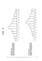
- FIG. 11 illustrates the tap coefficient gravity center before the correction and after the correction.
- the updated tap coefficients read out from the adaptive equalizer 23 are shifted by the calculated gravity center correction amount.
- the tap coefficients of the FIR filters that process the HH sequence and the VH sequence connected to the H polarization output are corrected by the same amount.
- the tap coefficients of the FIR filters that process the W sequence and the HV sequence connected to the V polarization output are corrected by the same amount.
- the correction of shifting the correction reference gravity center pGH of the H polarization by +2 taps (+1 symbol) and the correction reference gravity center pGV of the V polarization by -2 taps (-1 symbol) is determined.
- the tap coefficients of the HH filter and the tap coefficients of the VH filter are shifted by +2 taps
- the tap coefficients of the W filter and the tap coefficients of the HV filter are shifted by -2 taps.
- the tap coefficient setting unit 32 writes the tap coefficients after the correction in the adaptive equalizer 23.
- FIG. 12 illustrates a state in which the tap coefficients after the correction are written.
- the coefficients in the real number part (R part) and the imaginary part (I part) are written in with regard to each of the four sequences of HH, VH, HV, and W.
- 104 tap coefficients are written in as follows.
- FIG. 13 illustrates a process flow executed by the tap coefficient control unit 30.
- the tap coefficient control unit 30 obtains the synchronization symbol difference between the H polarization and the V polarization from the symbol synchronization monitor unit 28 (S101).
- the tap coefficient control unit 30 reads out the tap coefficients set in the individual filters from the adaptive equalizer 23 in concurrence with S101 or before or after S101 (S102).
- the tap coefficient gravity centers (GH and GV) are calculated with respect to the read tap coefficients (S103).
- the tap coefficient gravity centers (GH and GV) represent the delay amounts of the adaptive equalizer.
- the correction reference gravity centers pGH and pGV are calculated on the basis of the obtained tap coefficient gravity centers (GH and GV) and the synchronization symbol difference between the polarizations obtained in S101 by using Expression (6) (S104).
- the correction amount of the tap coefficients is determined in units of symbol on the basis of the correction reference gravity centers pGH and pGV (S105).
- the tap coefficient correction amount is the shift amount for shifting the correction reference gravity centers pGH and pGV towards a region in the vicinity of the tap center.
- the shift amount of the tap coefficients is determined in units of symbol (in units of two taps in the case of the twofold oversampling, and in units of four taps in the case of the fourfold oversampling).
- the correction of shifting the entire tap coefficients of the filters (the HH filter and the VH filter of FIG. 1 ) for the H polarization output is conducted on the basis of the determined tap coefficient correction amount, and the correction of shifting the entire tap coefficients of the filters (the HV filter and the VV filter of FIG. 1 ) for the V polarization output is conducted (S106).
- FIG. 14A and FIG. 14B illustrate an effect of the tap correction method according to the above-mentioned embodiment.
- a horizontal axis of the graphic representation represents the differential group delay (ps)
- a vertical axis represents a Q value (dB).
- the Q value is decreased, and the dispersion is increased.
- the method according to the embodiment even when the DGD is increased, the Q value is almost unchanged, and the dispersion is minute. This is because the fluctuation center of the tap coefficient gravity center is used as the reference for the gravity center correction.
- the correction of shifting the gravity centers of the tap coefficients towards the tap center is more accurately executed by using the correction reference gravity centers pGH and pGV obtained from the synchronization symbol difference between the polarizations and the delay amounts of the adaptive equalizer (the tap coefficient gravity centers according to the embodiment). As a result, the synchronization symbol difference becomes zero, and the performance of the adaptive equalizer can be maximized.
- FIG. 15A and FIG. 15B illustrate a modified example.
- the gravity center correction is conducted by the following expression.
- pGH GH + GV 2 + SYMBOL_DIFF ⁇ m 2
- pGV GH + GV 2 - SYMBOL_DIFF ⁇ m 2
- the DGD resistance is significantly improved as compared with the related art method, but the errors of the tap coefficient gravity centers (GH and GV) may be increased in several cases, and the correction reference gravity centers (pGH and pGV) may not be accurately calculated in some cases.
- pGH Adaptive equalizer delay + SYMBOL_DIFF ⁇ (m/2)
- pGV Adaptive equalizer delay - SYMBOL_DIFF ⁇ (m/2) (7)
- the adaptive equalizer delay is a location of the entire signals in the adaptive equalizer 23 (deviation from the tap center). Therefore, the delay amount of the adaptive equalizer 23 can also simply perform the calculation from the tap coefficient gravity centers (GH and GV). However, the tap coefficient gravity center reflects not only the delay amount but also an excessive component.
- the delay amount can be calculated from the tap coefficient gravity center at a significant accuracy.
- a deviation from the transmission path model may be increased in the actual transmission path.
- a large amount of obstructive components are included in the tap coefficient gravity center value, and the error at the time of the calculation for the delay amount is increased.
- a band property has a left-right asymmetry with respect to the wavelength of the signal light in the actual transmission path.
- a high order polarization mode dispersion (PMD) is also generated, and it is supposed that the transmission path model becomes more complex.
- M(n) is calculated from the tap coefficients of the adaptive equalizer 23 according to the modified example.
- M(n) is obtained by calculating a determinant from the coefficient value that has been subjected to discrete Fourier transform. The wavelength dispersion component and the delay amount component remain in M(n) at this time as illustrated in Expression (8).
- M n exp j cD 2 ⁇ ⁇ ⁇ f c 2 ⁇ ⁇ n 2 + j ⁇ 2 ⁇ ⁇ 0 ⁇ ⁇ n
- c denotes a light speed
- D denotes a wavelength dispersion
- fc denotes a center frequency of the carrier wave
- ⁇ denotes an angular frequency
- ⁇ denotes a delay amount.
- the delay amount is calculated through a differentiation of M(n).
- the tap coefficients of the adaptive equalizer having a tap number N are represented by Expression (9).
- w HH k , w HV k , w VH k , w VV k ⁇ k 1 , ⁇ , N
- M 1 n M n ⁇ M * ⁇ n + 1
- M 2 (n) M 1 n ⁇ M 1 * ⁇ n + 1
- the primary delay amount M 1 (n) of M(n) is used as an argument for the adaptive equalizer delay used in Expression (7).
- Adaptive equalizer delay - N 4 ⁇ ⁇ ⁇ f s ⁇ arg M 1 0 ⁇
- fs denotes a sampling frequency of the analog/digital converter (ADC)
- N denotes the tap number
- the delay amount is directly calculated from the tap coefficients. Therefore, it is possible to obtain the correction reference gravity centers pGH and pGV more accurately by using the adaptive equalizer delay in Expression (13) for Expression (7) as compared with the case in which the tap coefficient gravity centers GH and GV are used.
- the correction reference gravity centers pGH and pGV are equivalent to the fluctuation centers of the tap coefficient gravity centers used according to the embodiment, but the gravity centers serving as the correction reference can be calculated without using the coefficient gravity centers.
- the error component 41 included in the adaptive equalizer coefficient is removed without depending on whether the actual transmission path is approximated to or deviated from the transmission path model, and it is possible to reflect the accurate delay amount.
- the secondary delay amount M 2 (n) of M(n) is used as an argument for the wavelength dispersion D(n), and the wavelength dispersion component is removed.
- the adaptive equalizer delay is represented by Expression (15).
- the correction of shifting the entire tap coefficients in units of symbol is conducted so that the differences between the correction reference gravity centers pGH and pGV (gravity center values serving as the correction references which are calculated on the basis of the delay amounts of the adaptive equalizer) and the tap center are set to be minimum.
- the gravity centers of the tap coefficients can be shifted to an optimal location, and it is possible to maximize the correction effect.
- the DGD resistance is improved, and the increase in bit errors can be suppressed.
- the present disclosure is not limited only to the embodiment and the modified example.
- the synchronization symbol difference between the H polarization and the V polarization may also be calculated by the tap coefficient correction unit 33 instead of the symbol synchronization monitor unit 28.
- the symbol synchronization monitor unit 28 notifies the tap coefficient correction unit 33 of the symbol synchronization time of the H polarization and the V polarization.
- the calculation method for the gravity center of the tap coefficients is not limited to the above-mentioned method according to the embodiment, and the tap location having the highest coefficient may also be set as the tap coefficient gravity center.
Landscapes
- Engineering & Computer Science (AREA)
- Computer Networks & Wireless Communication (AREA)
- Signal Processing (AREA)
- Power Engineering (AREA)
- Optical Communication System (AREA)
- Digital Transmission Methods That Use Modulated Carrier Waves (AREA)
- Cable Transmission Systems, Equalization Of Radio And Reduction Of Echo (AREA)
- Physics & Mathematics (AREA)
- Electromagnetism (AREA)
Abstract
Description
- The embodiment discussed herein is related to an adaptive equalizer tap coefficient correction method and an optical receiver.
- In recent years, a research on an optical communication based on a digital coherent system has been advanced to cope with an increase in communication traffics. A waveform distortion correction, an adaptive equalization, and the like are carried out by a digital signal processing circuit in a digital coherent receiver, and high characteristics can be obtained even in a transmission at a high bit rate. In a case where a dual polarization-quadrature phase shift keying (DP-QPSK) modulation system is employed, two-bit data may be allocated to four modulated optical phases (0°, 90°, 180°, and 270°) with regard to each of two orthogonal polarizations, and a symbol speed may be reduced to a quarter of the original speed.
- The received optical signal is subjected to a photoelectric conversion and an analog/digital conversion, and waveform distortion components and the like are adaptively equalized by an adaptive equalizer in the digital signal processing circuit.
- The adaptive equalizer illustrated in
FIG. 1 is composed of a butterfly finite impulse response (FIR) filter and adapted to perform a separation of a polarized orthogonal multiple signal, a polarization mode dispersion compensation, and the like. A constant modulus algorithm (CMA) system is used for an adaptive control on tap coefficients of the individual filters, for example. A convergence state is unchanged even when all the tap coefficients on an H side (or all the tap coefficients on a V side) in units of one symbol (in units of the tap number corresponding to one symbol) are shifted by the FIR filter. This is because, when all the tap coefficients are shifted at once, only the absolute time is changed, and the relationship is maintained. In a case where twofold oversampling data is processed, a gravity center location of the tap coefficients in units of two taps (one symbol) is adjusted by shifting the entire tap coefficients so that the signal communication can be resumed without a second pull-in. - In a case where the weight of the tap coefficients is deviated to an end part of the taps, for example, a case where the coefficient value of the
tap number 1 or thetap number 13 is high in the 13-tap FIR filter, the equalization residual of the adaptive equalizer is generated, and the signal degradation is caused. For that reason, the weight of the tap coefficients is desirably shifted towards a center of the taps as much as possible. - A specific correction method of shifting the gravity center of the tap coefficients towards the tap center as much as possible is proposed (for example, see Japanese Laid-open Patent Publication No.
2012-119923 tap number 6 and thetap number 8 in the case of the 13-tap filter). That is, in a case where a horizontal axis represents the tap number and a vertical axis represents the tap coefficient, a tap number or a nearest tap number with which the area of a drawn figure is halved is referred to as "gravity center of the tap coefficients". The gravity center of the tap coefficients is calculated with respect to each of the H polarization and the V polarization, and the correction of shifting the gravity center of the tap coefficients towards the center of the taps is also conducted with respect to each of the H side and the V side. - According to the related art method, to carry out the correction of shifting the gravity center of the tap coefficients towards the tap center, an instantaneous value representing the tap coefficient gravity center at that moment is used. According to this method, an optimal correction is not carried out depending on a state of the polarizations, and a correction effect is not attained to a maximum extent. As a result, a differential group delay (DGD) resistance is decreased, and a bit error is likely to increase.
- In view of the above, a method and a configuration in which a tap coefficient correction effect of the adaptive equalizer is improved, and the adaptive equalization can be conducted at a satisfactory accuracy.
- According to an aspect of the invention, a method of tap coefficient correction includes: obtaining a synchronization symbol difference between a first polarization and a second polarization orthogonal to the first polarization; obtaining a delay amount of each of the first polarization and the second polarization in an adaptive equalizer; calculating, in a case where a horizontal axis represents a tap number and a vertical axis represents a tap coefficient and a tap number or a nearest tap number with which an area of a drawn figure is halved is set as a gravity center of tap coefficients, a correction reference gravity center of the tap coefficients set in the adaptive equalizer, based on the synchronization symbol difference and the delay amount; and performing a correction of shifting an entire tap coefficients in units of symbol to cause the correction reference gravity center to be closest to a tap center.
-
-
FIG. 1 is a schematic configuration diagram of an adaptive equalizer composed of a butterfly FIR filter; -
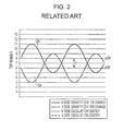
FIG. 2 is a graphic presentation of fluctuations of tap coefficient gravity center locations of an H polarization and a V polarization; -
FIG. 3A and FIG. 3B are explanatory diagrams for describing a problem in a tap coefficient correction method in related art; -
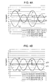
FIG. 4A and FIG. 4B are explanatory diagrams for describing a principle of a tap coefficient correction method according to an embodiment; -
FIG. 5 is a schematic diagram of an optical communication system to which the method according to the embodiment is applied; -
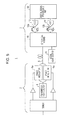
FIG. 6 is a schematic diagram of a digital signal processing unit according to the embodiment; -
FIG. 7 illustrates a state in which a symbol synchronization time is obtained; -
FIG. 8 illustrates a state in which tap coefficients are read out; -
FIG. 9 is an explanatory diagram for describing a method of obtaining the fluctuation centers of the coefficient gravity centers of the respective polarizations; -
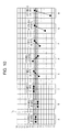
FIG. 10 illustrates a state in which the tap coefficient correction amount is determined; -
FIG. 11 illustrates a state in which the tap coefficient correction is executed; -
FIG. 12 illustrates a state in which tap coefficients after the correction are written in; -
FIG. 13 is a flow chart for the tap coefficient correction method according to the embodiment; -
FIG. 14A and FIG. 14B are explanatory diagrams for describing an effect of the correction method according to the embodiment; and -
FIG. 15A and FIG. 15B are explanatory diagrams for describing an effect of a modified example. - The problem of the tap coefficient correction method in related art which has been found by the applicants of the present application will be described with reference to
FIG. 2 . The gravity centers of the tap coefficients set in the adaptive equalizer are changed so that the gravity center locations of the tap coefficients on an H side and a V side are symmetric to each other by polarization rotations. If it is assumed that the polarization rotations are uniform, the fluctuations of the gravity center locations of the tap coefficients appear as periodic fluctuations like sign waves. The actual polarization rotations are not uniform and are changed in a complex manner. - A maximum amplitude of the fluctuation of the tap coefficient gravity center GH on the H side and a maximum amplitude of the fluctuation of the tap coefficient gravity center GV on the V side are determined on the basis of the differential group delay (DGD) amount. When a fluctuation center of the tap coefficient gravity center GH of the H polarization is set as pGH, and a fluctuation center of the tap coefficient gravity center GV of the V polarization is set as pGV, a difference between pGH and pGV is equivalent to a synchronization symbol difference. When a digital sampling rate is set as two samples per symbol, in the case of
FIG. 2 , a synchronization symbol difference of two taps, that is, one symbol is caused. - If a correction of simply shifting the tap coefficient gravity center at any given time towards the tap central part (for example, in a range between the
tap number 6 and thetap number 8 in a 13-tap filter) is executed, the situation may unexpectedly be deteriorated in some cases. This problem will be described with reference toFIG. 3A and FIG. 3B . - In
FIG. 3A , at a time t1, the tap coefficient gravity center (black circle) of the H polarization is located between thetap number 5 and thetap number 6, and the tap coefficient gravity center (white circle) of the V polarization is located between thetap number 9 and thetap number 10. Although the fluctuation center pGV of the tap coefficient gravity center GV of the V polarization is at the tap central part, the fluctuation change pGH of the tap coefficient gravity center GH of the H polarization is deviated in a direction towards a higher tap number. Under normal circumstances, a correction of pulling in the tap coefficient gravity center of the H polarization towards the central part (in a direction towards a lower tap number) is to be conducted. - However, if attention is paid only on the tap coefficient gravity center value at the time t1 and the correction of shifting the coefficient gravity center towards the tap center is conducted, as illustrated in
FIG. 3B , a correction of raising the coefficient gravity center (black circle) at a bottom of the fluctuation towards the tap center is executed. As a result, the tap coefficient gravity center GH of the H polarization fluctuates in a region farther away from the tap center. - On the other hand, the tap coefficient gravity center GV of the V polarization at t1 is out of the tap central part, but since the fluctuation center pGV is the vicinity of the tap center, it is conceivable that the correction may not be carried out. However, according to the correction method in related art, a correction of dragging down the coefficient gravity center (white circle) at a peak of the fluctuation towards the tap center is executed. As a result, the tap coefficient gravity center GV of the V polarization that has fluctuated in the tap central part is unexpectedly reshifted from the tap center.
- The gravity center of the tap coefficients indicates an entire signal location and represents a delay amount of the signal. According to the method in related art, the gravity centers of the tap coefficients of the H polarization and the V polarization may be deviated to the both ends of the taps in some cases, the adaptive equalization may not be properly executed. According to the embodiment, this problem is to be solved, and the effect of the adaptive equalization is maximized.
-
FIG. 4A and FIG. 4B are explanatory diagrams for describing a principle of a principle of the tap coefficient correction method according to the embodiment. According to the embodiment, an instantaneous coefficient gravity center value is not set as it is as a reference for the gravity center correction, but a fluctuation center of the gravity center of the tap coefficients is used as the reference for the gravity center correction. While a correction of shifting the fluctuation center of the gravity center towards the tap center is conducted, the gravity center correction of the tap coefficients is more accurately carried out. - In
FIG. 4A , the tap coefficient gravity center GV of the V polarization at a time t2 is at a bottom of the fluctuation. According to the related art method, the correction of shifting the tap coefficient gravity center GV by the 4 taps (2 symbols) towards the higher tap number direction is executed at this time. According to the embodiment, attention is paid on the fluctuation center pGV of the tap coefficient gravity center GV. Since the fluctuation center pGV at the time t2 exists in the tap central part (in the range between thetap number 6 and the tap number 8), the correction is not to be carried out. - On the other hand, the tap coefficient gravity center pGH of the H polarization at the time t2 is at a peak of the fluctuation. According to the related art method, the correction of shifting the coefficient gravity center by the 4 taps (2 symbols) towards the lower tap number direction is executed at this time. However, when attention is paid on the fluctuation change pGH of the tap coefficient gravity center GH, the fluctuation change pGH at the time t2 is slightly deviated from the tap central part. In view of the above, the fluctuation change pGH is shifted by the two taps (one symbol) towards the lower tap number direction.
- As illustrated in
FIG. 4B , the gravity center movement is not conducted with respect to the V polarization, and the fluctuation change pGH of the tap coefficient gravity center in the H polarization is shifted by one symbol towards the tap center. As a result, the fluctuation centers of the tap coefficient gravity centers of the H polarization and the V polarization are almost matched with each other. A synchronization symbol difference between the polarizations is cancelled (to be zero), and it is possible to bring out the correction effect to the maximum extent. As a result, the DGD resistance is improved, the increase in bit errors is suppressed. - According to the embodiment below, since the fluctuation centers pGH and pGV of the tap coefficient gravity centers are used as the correction reference gravity centers, the fluctuation centers are appropriately referred to as "correction reference gravity center pGH" and "correction reference gravity center pGV".
-
FIG. 5 is a schematic diagram of an optical communication system to which the tap coefficient correction method according to the embodiment is applied. Anoptical communication system 1 includes anoptical transmitter 2 and anoptical receiver 3 which are connected to each other via anoptical transmission path 5. - Light emitted from a
transmission light source 4 of theoptical transmitter 2 is guided tophase modulators optical transmission path 5. The optical signal received by theoptical receiver 3 is mixed with local oscillation light from a locallight source 11 at a 90° optical hybrid (optical mixer) 10, and an in phase (I) interference component and a quadrature (Q) interference component are output tolight sensors 12 such asbalanced photo diodes balanced photo diodes ADCs ADCs signal processing unit 20. For convenience of the illustration, the polarization separation is omitted on both the transmission side and the reception side inFIG. 5 , and only processing with respect to one polarization is illustrated, but similar processing is carried out with respect to the other polarization. -
FIG. 6 is a configuration diagram of the digitalsignal processing unit 20 illustrated inFIG. 5 . The digitalsignal processing unit 20 includes a fixedequalizer 21, asampling phase adjuster 22, anadaptive equalizer 23, a frequency offsetcompensation unit 24, a carrierphase restoration unit 25, a trainingsignal synchronization unit 26, a symbolsynchronization monitor unit 28, and a tapcoefficient control unit 30. - The tap
coefficient control unit 30 includes a tapcoefficient obtaining unit 31, a tapcoefficient setting unit 32, and a tapcoefficient correction unit 33. - The waveform distortion of the digital input signal is suppressed by the fixed
equalizer 21. The digital input signal is subjected to a phase adjustment by thesampling phase adjuster 22 and input to theadaptive equalizer 23. As illustrated inFIG. 1 , the H polarization input to theadaptive equalizer 23 includes the H polarization component (HH sequence) and the V polarization component (HV sequence) at the time of the transmission. The V polarization input to theadaptive equalizer 23 includes the V polarization component (W sequence) and the H polarization component (VH sequence) at the time of the transmission. Since the optical signal is received in a state in which the components of the H axis and the V axis are mixed with each other, the H component and the V component at the time of the transmission are restored by using the four sequences of HH, HV, VH, and W in the adaptive equalizer (polarization separation). - The
adaptive equalizer 23 includes a finite impulse response (FIR) filter corresponding to the HH, HV, VH, and W sequences. The tap coefficients of the individual FIR filters are controlled by the tapcoefficient control unit 30. The specific tap coefficient control will be described below. - The frequency offset
compensation unit 24 compensates an optical frequency deviation (offset) between thetransmission light source 4 and the locallight source 11. The carrierphase restoration unit 25 corrects a phase difference between thetransmission light source 4 and the locallight source 11. The trainingsignal synchronization unit 26 detects training sequences for synchronization of the individual sequences of HH, HV, VH, and W and establishes the synchronization between the sequences. - The symbol
synchronization monitor unit 28 obtains the symbol synchronization times of the H polarization and the V polarization to detect the synchronization symbol difference between the polarizations and supplies the detection result to the tapcoefficient correction unit 33 of the tapcoefficient control unit 30. - The synchronization symbol difference is detected from the training sequences according to the embodiment, but the present disclosure is not limited to this example. For example, in a case where a multi-lane distribution (MLD) is adopted, an inter-lane synchronization unit may be provided, and the symbol
synchronization monitor unit 28 may be configured to obtain the synchronization time from the inter-lane synchronization unit. -
FIG. 7 is an explanatory diagram for describing a state in which the symbol synchronization time is obtained by the symbolsynchronization monitor unit 28. The synchronization symbol difference between the polarizations is represented by a difference between the synchronization time of the V polarization and the synchronization time of the H polarization. - In a case where the H polarization is synchronized first, and the V polarization is synchronized thereafter, the synchronization symbol difference is assigned with a plus sign herein. In a case where the V polarization is synchronized first, and the H polarization is synchronized thereafter, the synchronization symbol difference is assigned with a minus sign. Since the symbol difference is relative, a definition of the coefficient shift of the tap coefficient correction unit may be reversed by reversing plus and minus.
- In the case of
FIG. 7 , the V polarization is synchronized in the 81st symbol section, and the H polarization is synchronized next in the 84th symbol section. The synchronization symbol difference between the polarizations is -3 symbols. This synchronization symbol difference is supplied to the tapcoefficient correction unit 33. -
FIG. 8 illustrates a state in which the tap coefficients are read out. The tapcoefficient obtaining unit 31 reads out tap coefficients of the individual filters constituting theadaptive equalizer 23. Coefficients in a real number part (R part) and an imaginary part (I part) are set in the individual sequences of HH, VH, HV, and W. In the case of the 13-tap filter, 104 tap coefficients are read out as follows. - 4 sequences × 2 × 13 taps = 104
- The
adaptive equalizer 23 executes a coefficient update algorithm in related art to update the coefficient value. A constant modulus algorithm (CMA) or a decision-directed least mean square (DD-LMS) algorithm can be used as the coefficient update algorithm. The tap coefficient read out by the tapcoefficient obtaining unit 31 is determined by the coefficient update algorithm in related art as described above. The correction is executed with respect to this coefficient by the tapcoefficient correction unit 33 and written back by the tapcoefficient setting unit 32. - The tap
coefficient correction unit 33 calculates the tap coefficient gravity center GH of the H polarization and the tap coefficient gravity center GV of the V polarization by using the read coefficient values. The tap coefficient gravity centers GH and GV are obtained from Expression (1).

- Where PHH, PVH, Pw, and PHV are total sum of power in all the tap numbers of the corresponding FIR filter and are represented by Expression (2).

- A calculation for a square of power of the individual tap numbers of the individual sequences (|*|2) is conducted by using the real (R) part and the imaginary (I) part as represented in Expression (3).

- Next, the tap
coefficient correction unit 33 uses the synchronization symbol difference obtained from the symbolsynchronization monitor unit 28 and the tap coefficient gravity centers GH and GV of the H polarization and the V polarization calculated as described above to calculate the correction reference gravity center (fluctuation center) pGH of the H polarization and the correction reference gravity center (fluctuation center) pGV of the V polarization. - When the synchronization symbol difference between the polarizations is set as SYMBOL_DIFF, and the tap coefficient gravity centers of the respective polarizations are set as (GH and GV), a deviation amount G_DELTA from the correction reference gravity centers of the tap coefficient gravity centers is represented as follows.

- The calculation in Expression (4) will be described with reference to
FIG. 9 . Values to be obtained at a time t3 with regard to the tap coefficient gravity center GH of the H polarization and the tap coefficient gravity center GV of the V polarization are the fluctuation centers pGH and pGV of the tap coefficient gravity centers corresponding to the correction reference gravity centers. The deviation amount G_DELTA from the correction reference gravity centers of the tap coefficient gravity centers of the respective polarizations at t3 is represented as follows.
- Herein, a case in which the twofold oversampling, that is, sampling data of two taps per symbol is processed is taken as an example.
- The correction reference gravity centers pGH and pGV are obtained from Expression (5).


- When Expression (4) is assigned to Expression (5), Expression (6) is obtained.


- In Expression (6), the correction reference gravity centers pGH and pGV of the H polarization and the V polarization can be calculated on the basis of the tap coefficient gravity center GH of the H polarization, the tap coefficient gravity center GV of the V polarization, and the synchronization symbol difference SYMBOL_DIFF between the polarizations.
- The tap
coefficient correction unit 33 determines the gravity center correction amount of the tap coefficients (shift amount) on the basis of the correction reference gravity centers pGH and pGV. -
FIG. 10 illustrates a state in which the tap coefficient correction (shift) amount is determined. The tapcoefficient correction unit 33 determines the correction amount so that the calculated correction reference gravity centers pGH and pGV are located in a tap center region Tc. In the example ofFIG. 10 , the correction amount is determined so as to satisfy 6 ≤ pGH ≤ 8 and 6 ≤ pGV ≤ 8. Since the gravity center correction is conducted in units of the symbol, the tap number to be shifted is an even number in the case of the twofold oversampling. - As represented in A, B, and C of
FIG. 10 , in a case where the correction reference gravity centers (the fluctuation centers of the tap coefficient gravity centers) are located in the tap center region Tc and 6 ≤ pGH ≤ 8 and 6 ≤ pGV ≤ 8 are satisfied, the gravity center correction amount is set as 0 symbols (0 taps). - As represented in D, E, and F of
FIG. 10 , in a case where the correction reference gravity centers is deviated in a range of 1 symbol or below from the tap center region Tc, the gravity center correction amount is set as +1 symbol (+2 taps) or -1 symbol (-2 taps). As represented in G ofFIG. 10 , in a case where the correction reference gravity centers is deviated from the tap center region Tc in a range of more than 1 symbol and 2 symbols or below, the gravity center correction amount is set as 2 symbols in the plus direction or the minus direction. In the case of H ofFIG. 10 , the gravity center correction amount is set as +3 symbols. -
FIG. 11 illustrates the tap coefficient gravity center before the correction and after the correction. The updated tap coefficients read out from theadaptive equalizer 23 are shifted by the calculated gravity center correction amount. According to the embodiment, the tap coefficients of the FIR filters that process the HH sequence and the VH sequence connected to the H polarization output are corrected by the same amount. Similarly, the tap coefficients of the FIR filters that process the W sequence and the HV sequence connected to the V polarization output (seeFIG. 1 ). - For example, it is supposed that the correction of shifting the correction reference gravity center pGH of the H polarization by +2 taps (+1 symbol) and the correction reference gravity center pGV of the V polarization by -2 taps (-1 symbol) is determined. In this case, the tap coefficients of the HH filter and the tap coefficients of the VH filter are shifted by +2 taps, and the tap coefficients of the W filter and the tap coefficients of the HV filter are shifted by -2 taps.
- In
FIG. 11 , in a case where the gravity center correction of shifting the tap coefficients of the HH filter by +1 symbol (+2 taps) is conducted, the entire coefficients of thetap numbers 1 to 13 are shifted by 2 taps towards the right side, and "0" is padded to thetap numbers - When the new tap coefficients are determined, the tap
coefficient setting unit 32 writes the tap coefficients after the correction in theadaptive equalizer 23. -
FIG. 12 illustrates a state in which the tap coefficients after the correction are written. The coefficients in the real number part (R part) and the imaginary part (I part) are written in with regard to each of the four sequences of HH, VH, HV, and W. In a case where the individual filter is the 13-tap filter, 104 tap coefficients are written in as follows. - 4 sequences × 2 × 13 taps = 104.
-
FIG. 13 illustrates a process flow executed by the tapcoefficient control unit 30. The tapcoefficient control unit 30 obtains the synchronization symbol difference between the H polarization and the V polarization from the symbol synchronization monitor unit 28 (S101). The tapcoefficient control unit 30 reads out the tap coefficients set in the individual filters from theadaptive equalizer 23 in concurrence with S101 or before or after S101 (S102). - The tap coefficient gravity centers (GH and GV) are calculated with respect to the read tap coefficients (S103). The tap coefficient gravity centers (GH and GV) represent the delay amounts of the adaptive equalizer.
- The correction reference gravity centers pGH and pGV (fluctuation centers of the tap coefficient gravity centers according to the embodiment) are calculated on the basis of the obtained tap coefficient gravity centers (GH and GV) and the synchronization symbol difference between the polarizations obtained in S101 by using Expression (6) (S104).
- The correction amount of the tap coefficients is determined in units of symbol on the basis of the correction reference gravity centers pGH and pGV (S105). The tap coefficient correction amount is the shift amount for shifting the correction reference gravity centers pGH and pGV towards a region in the vicinity of the tap center. As described above, the shift amount of the tap coefficients is determined in units of symbol (in units of two taps in the case of the twofold oversampling, and in units of four taps in the case of the fourfold oversampling).
- The correction of shifting the entire tap coefficients of the filters (the HH filter and the VH filter of
FIG. 1 ) for the H polarization output is conducted on the basis of the determined tap coefficient correction amount, and the correction of shifting the entire tap coefficients of the filters (the HV filter and the VV filter ofFIG. 1 ) for the V polarization output is conducted (S106). - Finally, the tap coefficients on which the gravity center correction has been conducted are written in the adaptive equalizer 23 (S107), and the processing is ended.
-
FIG. 14A and FIG. 14B illustrate an effect of the tap correction method according to the above-mentioned embodiment. InFIG. 14A and FIG. 14B , a horizontal axis of the graphic representation represents the differential group delay (ps), and a vertical axis represents a Q value (dB). With regard to both the method in related art and the method according to the embodiment, a simulation result based on a bit error rate (the number of reception error bits/the number of transmitted bits) is converted into the Q value. - According to the related art system, as the DGD is increased, the Q value is decreased, and the dispersion is increased. On contrast to this, with the method according to the embodiment, even when the DGD is increased, the Q value is almost unchanged, and the dispersion is minute. This is because the fluctuation center of the tap coefficient gravity center is used as the reference for the gravity center correction. The correction of shifting the gravity centers of the tap coefficients towards the tap center is more accurately executed by using the correction reference gravity centers pGH and pGV obtained from the synchronization symbol difference between the polarizations and the delay amounts of the adaptive equalizer (the tap coefficient gravity centers according to the embodiment). As a result, the synchronization symbol difference becomes zero, and the performance of the adaptive equalizer can be maximized.
- Modified Example
-
FIG. 15A and FIG. 15B illustrate a modified example. According to the above-mentioned embodiment, the gravity center correction is conducted by the following expression.

- In Expression (6'), m denotes an oversampling rate.
- According to the method according to the embodiment, the DGD resistance is significantly improved as compared with the related art method, but the errors of the tap coefficient gravity centers (GH and GV) may be increased in several cases, and the correction reference gravity centers (pGH and pGV) may not be accurately calculated in some cases.
- In view of the above, according to the modified example, the correction reference gravity centers (pGH and pGV) are calculated by Expression (7).
- pGH = Adaptive equalizer delay + SYMBOL_DIFF·(m/2)
- pGV = Adaptive equalizer delay - SYMBOL_DIFF·(m/2) (7)
- The adaptive equalizer delay is a location of the entire signals in the adaptive equalizer 23 (deviation from the tap center). Therefore, the delay amount of the
adaptive equalizer 23 can also simply perform the calculation from the tap coefficient gravity centers (GH and GV). However, the tap coefficient gravity center reflects not only the delay amount but also an excessive component. - If a transmission path model and an actual transmission path are approximated to each other, the delay amount can be calculated from the tap coefficient gravity center at a significant accuracy. However, a deviation from the transmission path model may be increased in the actual transmission path. As a result, a large amount of obstructive components are included in the tap coefficient gravity center value, and the error at the time of the calculation for the delay amount is increased.
- For example, it is supposed that a band property has a left-right asymmetry with respect to the wavelength of the signal light in the actual transmission path. A high order polarization mode dispersion (PMD) is also generated, and it is supposed that the transmission path model becomes more complex.
- As illustrated in
FIG. 15A , in a case where the actual transmission path is close to the transmission path model,error components 41 that reflects the tap coefficients of theadaptive equalizer 23 and the gravity center value thereof are little. When the actual transmission path is deviated from the transmission path model, theerror components 41 are increased in both the tap coefficients of theadaptive equalizer 23 and the gravity center value thereof, and the delay amount may not be accurately obtained. - In view of the above, M(n) is calculated from the tap coefficients of the
adaptive equalizer 23 according to the modified example. M(n) is obtained by calculating a determinant from the coefficient value that has been subjected to discrete Fourier transform. The wavelength dispersion component and the delay amount component remain in M(n) at this time as illustrated in Expression (8).
- Where c denotes a light speed, D denotes a wavelength dispersion, fc denotes a center frequency of the carrier wave, ω denotes an angular frequency, and τ denotes a delay amount. In view of the above, the delay amount is calculated through a differentiation of M(n).
- More specifically, the tap coefficients of the adaptive equalizer having a tap number N are represented by Expression (9).

- Processing of obtaining the determinant by subjecting this coefficient to the discrete Fourier transform is represented by Expression (10).

- When M(n) is differentiated once, a primary delay amount M1(n) is represented by Expression (11).

- When M(n) is differentiated twice, a secondary delay amount M2(n) is represented by Expression (12).

- According to a first method, the primary delay amount M1(n) of M(n) is used as an argument for the adaptive equalizer delay used in Expression (7).

- Where fs denotes a sampling frequency of the analog/digital converter (ADC), and N denotes the tap number.
- In Expression (13), the delay amount is directly calculated from the tap coefficients. Therefore, it is possible to obtain the correction reference gravity centers pGH and pGV more accurately by using the adaptive equalizer delay in Expression (13) for Expression (7) as compared with the case in which the tap coefficient gravity centers GH and GV are used. The correction reference gravity centers pGH and pGV are equivalent to the fluctuation centers of the tap coefficient gravity centers used according to the embodiment, but the gravity centers serving as the correction reference can be calculated without using the coefficient gravity centers.
- According to this method, as illustrated in
FIG. 15B , theerror component 41 included in the adaptive equalizer coefficient is removed without depending on whether the actual transmission path is approximated to or deviated from the transmission path model, and it is possible to reflect the accurate delay amount. - According to a second method, as represented in Expression (14), the secondary delay amount M2 (n) of M(n) is used as an argument for the wavelength dispersion D(n), and the wavelength dispersion component is removed.


- In this case, the adaptive equalizer delay is represented by Expression (15).


- According to this method, it is possible to still more accurately obtain the correction reference gravity centers as compared with the first method.
- As described above, according to the embodiment and the modified example, the correction of shifting the entire tap coefficients in units of symbol is conducted so that the differences between the correction reference gravity centers pGH and pGV (gravity center values serving as the correction references which are calculated on the basis of the delay amounts of the adaptive equalizer) and the tap center are set to be minimum. With this configuration, the gravity centers of the tap coefficients can be shifted to an optimal location, and it is possible to maximize the correction effect. As a result, the DGD resistance is improved, and the increase in bit errors can be suppressed.
- It is noted that the present disclosure is not limited only to the embodiment and the modified example. For example, the synchronization symbol difference between the H polarization and the V polarization may also be calculated by the tap
coefficient correction unit 33 instead of the symbolsynchronization monitor unit 28. In this case, the symbolsynchronization monitor unit 28 notifies the tapcoefficient correction unit 33 of the symbol synchronization time of the H polarization and the V polarization. In addition, the calculation method for the gravity center of the tap coefficients is not limited to the above-mentioned method according to the embodiment, and the tap location having the highest coefficient may also be set as the tap coefficient gravity center.
Claims (15)
- A method of tap coefficient correction, comprising:obtaining a synchronization symbol difference between a first polarization and a second polarization orthogonal to the first polarization;obtaining a delay amount of each of the first polarization and the second polarization in an adaptive equalizer;calculating, in a case where a horizontal axis represents a tap number and a vertical axis represents a tap coefficient and a tap number or a nearest tap number with which an area of a drawn figure is halved is set as a gravity center of tap coefficients, a correction reference gravity center of the tap coefficients set in the adaptive equalizer, based on the synchronization symbol difference and the delay amount; andperforming a correction of shifting an entire tap coefficients in units of symbol to cause the correction reference gravity center to be closest to a tap center.
- The method according to claim 1,
wherein the delay amount is obtained from a gravity center of first tap coefficients set in the adaptive equalizer for the first polarization and a gravity center of second tap coefficients set in the adaptive equalizer for the second polarization, and
wherein a fluctuation center of the gravity center of the first tap coefficients is calculated as a first correction reference gravity center on the basis of the synchronization symbol difference and the delay amount, and a fluctuation center of the gravity center of the second tap coefficients is calculated as a second correction reference gravity center. - The method according to claim 2,
wherein a correction of shifting the entire first tap coefficients and the entire second tap coefficients in units of symbol is conducted to cause the first correction reference gravity center and the second correction reference gravity center to be closest to the tap center. - The method according to claim 1,
wherein the delay amount is obtained by differentiating a determinant represented by first tap coefficients set in the adaptive equalizer for the first polarization and second tap coefficients set in the adaptive equalizer for the second polarization. - The method according to claim 4,
wherein the delay amount is obtained while a primary delay amount obtained by differentiating the determinant once is set as an argument. - The method according to claim 5,
wherein the delay amount is obtained while a wavelength dispersion is removed by a secondary delay amount obtained by differentiating the determinant twice. - The method according to any one of claims 1 to 6,
wherein the synchronization symbol difference is obtained as a difference between a symbol synchronization time of the first polarization and a symbol synchronization time of the second polarization. - The method according to any one of claims 1 to 7,
wherein the tap coefficients are read out from the adaptive equalizer before the correction reference gravity center is calculated. - An optical receiver, comprising:a receiver configured to receive an optical signal and output an electric signal;a converter configured to convert the electric signal into a digital signal;an adaptive equalizer configured to adaptively equalize the digital signal;a monitor configured to monitor a symbol synchronization time of a first polarization included in the digital signal that has been adaptively equalized and a symbol synchronization time of a second polarization orthogonal to the first polarization; anda tap coefficient controller connected to the adaptive equalizer and the monitor and configured to control tap coefficients set in the adaptive equalizer,wherein the tap coefficient controller configured to:obtain a synchronization symbol difference between the first polarization and the second polarization, based on an output of the monitor,obtain a delay amount of the first polarization and the second polarization in the adaptive equalizer,calculate, based on the synchronization symbol difference and the delay amount, a correction reference gravity center of the tap coefficients set in the adaptive equalizer where a horizontal axis represents a tap number and a vertical axis represents a tap coefficient and a tap number or a nearest tap number with which an area of a drawn figure is halved is set as a gravity center of tap coefficients, andperform a correction of shifting the entire tap coefficients in units of symbol to cause the correction reference gravity center to be closest to a tap center.
- The optical receiver according to claim 9,
wherein the adaptive equalizer has first tap coefficients for the first polarization and second tap coefficients for the second polarization, and
wherein the tap coefficient controller calculates a gravity center of the first tap coefficients and a gravity center of the second tap coefficients, calculates a fluctuation center of the gravity center of the first tap coefficients as a first correction reference gravity center on the basis of the gravity center of the first tap coefficients and the gravity center of the second tap coefficients, and the synchronization symbol difference, and calculates a fluctuation center of the gravity center of the second tap coefficients as a second correction reference gravity center. - The optical receiver according to claim 10,
wherein the tap coefficient controller performs a correction of shifting the entire first tap coefficients and the entire second tap coefficients in units of symbols to cause the first correction reference gravity center and the second correction reference gravity center to be closest to the tap center. - The optical receiver according to claim 9,
wherein the adaptive equalizer includes first tap coefficients for the first polarization and second tap coefficients for the second polarization, and
wherein the tap coefficient controller obtains the delay amount by differentiating a determinant represented by the first tap coefficients and the second tap coefficients. - The optical receiver according to claim 12,
wherein the tap coefficient controller obtains the delay amount while a primary delay amount obtained by differentiating the determinant once is set as an argument. - The optical receiver according to claim 13,
wherein the tap coefficient controller obtains the delay amount while a wavelength dispersion is removed by a secondary delay amount obtained by differentiating the determinant twice. - The optical receiver according to any one of claims 9 to 14,
wherein the tap coefficient controller obtains the synchronization symbol difference on the basis of a difference between a symbol synchronization time of the first polarization and a symbol synchronization time of the second polarization.
Applications Claiming Priority (1)
| Application Number | Priority Date | Filing Date | Title |
|---|---|---|---|
| JP2013017236A JP6065618B2 (en) | 2013-01-31 | 2013-01-31 | Adaptive equalizer tap coefficient correction method and optical receiver |
Publications (3)
| Publication Number | Publication Date |
|---|---|
| EP2763366A2 true EP2763366A2 (en) | 2014-08-06 |
| EP2763366A3 EP2763366A3 (en) | 2014-08-20 |
| EP2763366B1 EP2763366B1 (en) | 2018-08-22 |
Family
ID=49639735
Family Applications (1)
| Application Number | Title | Priority Date | Filing Date |
|---|---|---|---|
| EP13193437.4A Not-in-force EP2763366B1 (en) | 2013-01-31 | 2013-11-19 | Adaptive equalizer tap coefficient correction method and optical receiver |
Country Status (4)
| Country | Link |
|---|---|
| US (1) | US9407471B2 (en) |
| EP (1) | EP2763366B1 (en) |
| JP (1) | JP6065618B2 (en) |
| CN (1) | CN103973614B (en) |
Cited By (1)
| Publication number | Priority date | Publication date | Assignee | Title |
|---|---|---|---|---|
| US10461968B2 (en) | 2015-06-29 | 2019-10-29 | Sanechips Technology Co., Ltd. | Adjustment method and device for equalizer coefficient, and computer storage medium |
Families Citing this family (20)
| Publication number | Priority date | Publication date | Assignee | Title |
|---|---|---|---|---|
| CN105103508A (en) * | 2013-03-30 | 2015-11-25 | 中兴通讯股份有限公司 | Recovering data from quadrature phase shift keying modulated optical signals |
| WO2015027903A1 (en) | 2013-08-27 | 2015-03-05 | Zte Corporation | Optical communication using super-nyquist signals |
| JP6213287B2 (en) * | 2014-02-13 | 2017-10-18 | 富士通株式会社 | Optical transmission device and signal processing method of optical transmission device |
| US9324364B2 (en) * | 2014-07-17 | 2016-04-26 | International Business Machines Corporation | Constraining FIR filter taps in an adaptive architecture |
| US9236084B1 (en) | 2014-07-17 | 2016-01-12 | International Business Machines Corporation | Dynamic gain control for use with adaptive equalizers |
| US9231787B1 (en) * | 2015-01-23 | 2016-01-05 | Huawei Technologies Co., Ltd. | Method and apparatus with improved estimation accuracy and robustness for fine frequency offset estimation in coherent receivers |
| US9497048B2 (en) * | 2015-01-23 | 2016-11-15 | Huawei Technologies Co., Ltd. | Method and apparatus with improved estimation accuracy and robustness for fine frequency offset estimation in coherent receivers |
| JP6297004B2 (en) * | 2015-03-09 | 2018-03-20 | 三菱電機株式会社 | Optical transmission apparatus and delay difference compensation method between adjacent channels applied to optical transmission apparatus |
| CN106330320B (en) * | 2015-06-24 | 2019-05-24 | 中兴通讯股份有限公司 | An adaptive equalizer and a method for realizing adaptive equalization processing |
| JP6684399B2 (en) * | 2016-05-31 | 2020-04-22 | 国立研究開発法人情報通信研究機構 | Coherent sampling |
| CN106888054B (en) * | 2017-03-08 | 2019-03-26 | 北京理工大学 | A Weighted Optimization Method for Dispersion Equalization in FIR Time Domain |
| CN107566307A (en) * | 2017-08-31 | 2018-01-09 | 北京睿信丰科技有限公司 | Blind equalizing apparatus and method, data modulation system and method |
| JP6950594B2 (en) * | 2018-03-09 | 2021-10-13 | 富士通株式会社 | Signal processing circuit and optical receiver |
| JP7007588B2 (en) * | 2018-06-18 | 2022-01-24 | 日本電信電話株式会社 | Signal processing device and optical receiver |
| CN112713941A (en) * | 2019-10-24 | 2021-04-27 | 富士通株式会社 | Device and method for determining static equalizer coefficient |
| JP7055268B2 (en) * | 2020-05-28 | 2022-04-18 | Nttエレクトロニクス株式会社 | Adaptive equalizer, adaptive equalization method and optical communication system |
| WO2023131985A1 (en) * | 2022-01-04 | 2023-07-13 | 日本電信電話株式会社 | Estimation method, optical receiving apparatus, and computer program |
| US12395384B1 (en) * | 2022-01-28 | 2025-08-19 | Acacia Technology, Inc. | Adaptive equalizer performance monitor |
| US20250379659A1 (en) * | 2022-07-13 | 2025-12-11 | Nippon Telegraph And Telephone Corporation | Sample interval synchronous position notification device, optical receiver and sample interval synchronous position notification method |
| US12512868B2 (en) * | 2023-04-12 | 2025-12-30 | Samsung Electronics Co., Ltd. | Method and apparatus for parallel self-interference estimation and cancellation in multiple transmitters carrier aggregation systems |
Citations (1)
| Publication number | Priority date | Publication date | Assignee | Title |
|---|---|---|---|---|
| JP2012119923A (en) | 2010-11-30 | 2012-06-21 | Fujitsu Ltd | Adaptive equalizer, optical receiver, and tap coefficient correction method of adaptive equalizer |
Family Cites Families (9)
| Publication number | Priority date | Publication date | Assignee | Title |
|---|---|---|---|---|
| JP2002101144A (en) * | 2000-09-22 | 2002-04-05 | Hitachi Kokusai Electric Inc | Digital demodulator |
| US7463679B2 (en) * | 2005-06-27 | 2008-12-09 | Intel Corporation | Equalizer mode selection based on distribution of symbol error |
| JP5444877B2 (en) * | 2009-06-24 | 2014-03-19 | 富士通株式会社 | Digital coherent receiver |
| GB2472082B (en) * | 2009-07-23 | 2015-05-27 | Coreoptics Inc | Clock recovery for optical transmission systems |
| US9100126B2 (en) * | 2009-11-24 | 2015-08-04 | Nec Corporation | Optical reception device and optical reception control method |
| JP5445260B2 (en) | 2010-03-19 | 2014-03-19 | 富士通株式会社 | Digital coherent receiver and digital coherent receiving method |
| JP5633352B2 (en) * | 2010-12-09 | 2014-12-03 | 富士通株式会社 | Digital coherent optical receiver, adaptive equalization equalizer, and digital coherent optical communication method |
| US8693897B2 (en) * | 2011-01-22 | 2014-04-08 | Viasat, Inc. | Digital demodulator architecture |
| WO2012122237A2 (en) * | 2011-03-07 | 2012-09-13 | Acacia Communications Incorporated | Turn-up and long term operation of adaptive equalizer in optical |
-
2013
- 2013-01-31 JP JP2013017236A patent/JP6065618B2/en active Active
- 2013-11-18 US US14/082,521 patent/US9407471B2/en active Active
- 2013-11-19 EP EP13193437.4A patent/EP2763366B1/en not_active Not-in-force
- 2013-12-05 CN CN201310652178.XA patent/CN103973614B/en not_active Expired - Fee Related
Patent Citations (1)
| Publication number | Priority date | Publication date | Assignee | Title |
|---|---|---|---|---|
| JP2012119923A (en) | 2010-11-30 | 2012-06-21 | Fujitsu Ltd | Adaptive equalizer, optical receiver, and tap coefficient correction method of adaptive equalizer |
Cited By (1)
| Publication number | Priority date | Publication date | Assignee | Title |
|---|---|---|---|---|
| US10461968B2 (en) | 2015-06-29 | 2019-10-29 | Sanechips Technology Co., Ltd. | Adjustment method and device for equalizer coefficient, and computer storage medium |
Also Published As
| Publication number | Publication date |
|---|---|
| JP2014150365A (en) | 2014-08-21 |
| JP6065618B2 (en) | 2017-01-25 |
| CN103973614B (en) | 2017-09-29 |
| EP2763366A3 (en) | 2014-08-20 |
| CN103973614A (en) | 2014-08-06 |
| US20140212132A1 (en) | 2014-07-31 |
| EP2763366B1 (en) | 2018-08-22 |
| US9407471B2 (en) | 2016-08-02 |
Similar Documents
| Publication | Publication Date | Title |
|---|---|---|
| EP2763366B1 (en) | Adaptive equalizer tap coefficient correction method and optical receiver | |
| US8478137B2 (en) | Optical receiver | |
| US8693898B2 (en) | Adaptive equalizer, optical receiver, and tap coefficient correcting method | |
| JP5238881B2 (en) | Adaptive nonlinear compensation in coherent receivers. | |
| US8687974B2 (en) | Skew compensation and tracking in communications systems | |
| JP6057382B2 (en) | Digital demodulator architecture | |
| JP5694605B2 (en) | Multimode communication optical receiver | |
| EP2709327B1 (en) | Updating apparatus and method for equalizer coefficient, receiver and optical communication system | |
| US8989602B2 (en) | Digital coherent optical receiver, adaptive equalizer, and digital coherent optical communication method | |
| EP3208952B1 (en) | Mitigation of electrical-to-optical conversion impairments induced at transmitter | |
| EP2159936A1 (en) | Method for electric power supply of optical receiver, digital signal processing circuit, and optical receiver | |
| US20110170881A1 (en) | Light receiving device and light receiving method | |
| US20130251370A1 (en) | Optical receiver, polarization separation device and polarization separating method | |
| EP3046300A1 (en) | Clock recovery method and device | |
| US9608735B2 (en) | MIMO equalization optimized for baud rate clock recovery in coherent DP-QPSK metro systems | |
| US8655195B2 (en) | Average length magnitude detecting apparatus, and method | |
| US20120155881A1 (en) | Electronic dispersion compensation system and method | |
| WO2017077802A1 (en) | Wavelength dispersion estimation circuit, optical receiver, and wavelength dispersion estimation method | |
| CN105530050A (en) | Joint processing method and device for equilibrium and polarization demultiplexing and phase offset estimation and compensation | |
| WO2019049616A1 (en) | Optical transmission characteristic estimation method, optical transmission characteristic compensation method, optical transmission characteristic estimation system, and optical transmission characteristic compensation system | |
| Zhu et al. | Frequency-domain blind equalization for long-haul coherent pol-mux 16-QAM system with CD prediction and dual-mode adaptive algorithm | |
| CN116325675B (en) | Digital signal processing method and apparatus for low-complexity symbol rate receivers | |
| CN111585646B (en) | Estimation device and method for relative time delay of polarization state | |
| JP6355465B2 (en) | Optical receiver, transmitter / receiver, optical communication system, and waveform distortion compensation method | |
| US9225433B1 (en) | Timing recovery for optical coherent receivers in the presence of polarization mode dispersion |
Legal Events
| Date | Code | Title | Description |
|---|---|---|---|
| PUAL | Search report despatched |
Free format text: ORIGINAL CODE: 0009013 |
|
| PUAI | Public reference made under article 153(3) epc to a published international application that has entered the european phase |
Free format text: ORIGINAL CODE: 0009012 |
|
| 17P | Request for examination filed |
Effective date: 20131119 |
|
| AK | Designated contracting states |
Kind code of ref document: A2 Designated state(s): AL AT BE BG CH CY CZ DE DK EE ES FI FR GB GR HR HU IE IS IT LI LT LU LV MC MK MT NL NO PL PT RO RS SE SI SK SM TR |
|
| AX | Request for extension of the european patent |
Extension state: BA ME |
|
| AK | Designated contracting states |
Kind code of ref document: A3 Designated state(s): AL AT BE BG CH CY CZ DE DK EE ES FI FR GB GR HR HU IE IS IT LI LT LU LV MC MK MT NL NO PL PT RO RS SE SI SK SM TR |
|
| AX | Request for extension of the european patent |
Extension state: BA ME |
|
| RIC1 | Information provided on ipc code assigned before grant |
Ipc: H04L 25/03 20060101AFI20140715BHEP Ipc: H04B 10/61 20130101ALI20140715BHEP |
|
| R17P | Request for examination filed (corrected) |
Effective date: 20141014 |
|
| RBV | Designated contracting states (corrected) |
Designated state(s): AL AT BE BG CH CY CZ DE DK EE ES FI FR GB GR HR HU IE IS IT LI LT LU LV MC MK MT NL NO PL PT RO RS SE SI SK SM TR |
|
| RIN1 | Information on inventor provided before grant (corrected) |
Inventor name: ARAKI, HIROFUMI Inventor name: SAITO, TAKU Inventor name: NAKASHIMA, HISAO Inventor name: KOIZUMI, NOBUKAZU Inventor name: TAKEUCHI, OSAMU |
|
| GRAP | Despatch of communication of intention to grant a patent |
Free format text: ORIGINAL CODE: EPIDOSNIGR1 |
|
| INTG | Intention to grant announced |
Effective date: 20180418 |
|
| GRAS | Grant fee paid |
Free format text: ORIGINAL CODE: EPIDOSNIGR3 |
|
| GRAA | (expected) grant |
Free format text: ORIGINAL CODE: 0009210 |
|
| AK | Designated contracting states |
Kind code of ref document: B1 Designated state(s): AL AT BE BG CH CY CZ DE DK EE ES FI FR GB GR HR HU IE IS IT LI LT LU LV MC MK MT NL NO PL PT RO RS SE SI SK SM TR |
|
| REG | Reference to a national code |
Ref country code: GB Ref legal event code: FG4D |
|
| REG | Reference to a national code |
Ref country code: FR Ref legal event code: PLFP Year of fee payment: 6 |
|
| REG | Reference to a national code |
Ref country code: CH Ref legal event code: EP |
|
| REG | Reference to a national code |
Ref country code: AT Ref legal event code: REF Ref document number: 1033772 Country of ref document: AT Kind code of ref document: T Effective date: 20180915 |
|
| REG | Reference to a national code |
Ref country code: IE Ref legal event code: FG4D |
|
| REG | Reference to a national code |
Ref country code: DE Ref legal event code: R096 Ref document number: 602013042304 Country of ref document: DE |
|
| REG | Reference to a national code |
Ref country code: NL Ref legal event code: MP Effective date: 20180822 |
|
| REG | Reference to a national code |
Ref country code: LT Ref legal event code: MG4D |
|
| PG25 | Lapsed in a contracting state [announced via postgrant information from national office to epo] |
Ref country code: FI Free format text: LAPSE BECAUSE OF FAILURE TO SUBMIT A TRANSLATION OF THE DESCRIPTION OR TO PAY THE FEE WITHIN THE PRESCRIBED TIME-LIMIT Effective date: 20180822 Ref country code: LT Free format text: LAPSE BECAUSE OF FAILURE TO SUBMIT A TRANSLATION OF THE DESCRIPTION OR TO PAY THE FEE WITHIN THE PRESCRIBED TIME-LIMIT Effective date: 20180822 Ref country code: NL Free format text: LAPSE BECAUSE OF FAILURE TO SUBMIT A TRANSLATION OF THE DESCRIPTION OR TO PAY THE FEE WITHIN THE PRESCRIBED TIME-LIMIT Effective date: 20180822 Ref country code: NO Free format text: LAPSE BECAUSE OF FAILURE TO SUBMIT A TRANSLATION OF THE DESCRIPTION OR TO PAY THE FEE WITHIN THE PRESCRIBED TIME-LIMIT Effective date: 20181122 Ref country code: SE Free format text: LAPSE BECAUSE OF FAILURE TO SUBMIT A TRANSLATION OF THE DESCRIPTION OR TO PAY THE FEE WITHIN THE PRESCRIBED TIME-LIMIT Effective date: 20180822 Ref country code: BG Free format text: LAPSE BECAUSE OF FAILURE TO SUBMIT A TRANSLATION OF THE DESCRIPTION OR TO PAY THE FEE WITHIN THE PRESCRIBED TIME-LIMIT Effective date: 20181122 Ref country code: RS Free format text: LAPSE BECAUSE OF FAILURE TO SUBMIT A TRANSLATION OF THE DESCRIPTION OR TO PAY THE FEE WITHIN THE PRESCRIBED TIME-LIMIT Effective date: 20180822 Ref country code: IS Free format text: LAPSE BECAUSE OF FAILURE TO SUBMIT A TRANSLATION OF THE DESCRIPTION OR TO PAY THE FEE WITHIN THE PRESCRIBED TIME-LIMIT Effective date: 20181222 Ref country code: GR Free format text: LAPSE BECAUSE OF FAILURE TO SUBMIT A TRANSLATION OF THE DESCRIPTION OR TO PAY THE FEE WITHIN THE PRESCRIBED TIME-LIMIT Effective date: 20181123 |
|
| REG | Reference to a national code |
Ref country code: AT Ref legal event code: MK05 Ref document number: 1033772 Country of ref document: AT Kind code of ref document: T Effective date: 20180822 |
|
| PG25 | Lapsed in a contracting state [announced via postgrant information from national office to epo] |
Ref country code: HR Free format text: LAPSE BECAUSE OF FAILURE TO SUBMIT A TRANSLATION OF THE DESCRIPTION OR TO PAY THE FEE WITHIN THE PRESCRIBED TIME-LIMIT Effective date: 20180822 Ref country code: LV Free format text: LAPSE BECAUSE OF FAILURE TO SUBMIT A TRANSLATION OF THE DESCRIPTION OR TO PAY THE FEE WITHIN THE PRESCRIBED TIME-LIMIT Effective date: 20180822 Ref country code: AL Free format text: LAPSE BECAUSE OF FAILURE TO SUBMIT A TRANSLATION OF THE DESCRIPTION OR TO PAY THE FEE WITHIN THE PRESCRIBED TIME-LIMIT Effective date: 20180822 |
|
| PG25 | Lapsed in a contracting state [announced via postgrant information from national office to epo] |
Ref country code: ES Free format text: LAPSE BECAUSE OF FAILURE TO SUBMIT A TRANSLATION OF THE DESCRIPTION OR TO PAY THE FEE WITHIN THE PRESCRIBED TIME-LIMIT Effective date: 20180822 Ref country code: CZ Free format text: LAPSE BECAUSE OF FAILURE TO SUBMIT A TRANSLATION OF THE DESCRIPTION OR TO PAY THE FEE WITHIN THE PRESCRIBED TIME-LIMIT Effective date: 20180822 Ref country code: IT Free format text: LAPSE BECAUSE OF FAILURE TO SUBMIT A TRANSLATION OF THE DESCRIPTION OR TO PAY THE FEE WITHIN THE PRESCRIBED TIME-LIMIT Effective date: 20180822 Ref country code: AT Free format text: LAPSE BECAUSE OF FAILURE TO SUBMIT A TRANSLATION OF THE DESCRIPTION OR TO PAY THE FEE WITHIN THE PRESCRIBED TIME-LIMIT Effective date: 20180822 Ref country code: EE Free format text: LAPSE BECAUSE OF FAILURE TO SUBMIT A TRANSLATION OF THE DESCRIPTION OR TO PAY THE FEE WITHIN THE PRESCRIBED TIME-LIMIT Effective date: 20180822 Ref country code: RO Free format text: LAPSE BECAUSE OF FAILURE TO SUBMIT A TRANSLATION OF THE DESCRIPTION OR TO PAY THE FEE WITHIN THE PRESCRIBED TIME-LIMIT Effective date: 20180822 Ref country code: PL Free format text: LAPSE BECAUSE OF FAILURE TO SUBMIT A TRANSLATION OF THE DESCRIPTION OR TO PAY THE FEE WITHIN THE PRESCRIBED TIME-LIMIT Effective date: 20180822 |
|
| REG | Reference to a national code |
Ref country code: DE Ref legal event code: R097 Ref document number: 602013042304 Country of ref document: DE |
|
| PG25 | Lapsed in a contracting state [announced via postgrant information from national office to epo] |
Ref country code: SK Free format text: LAPSE BECAUSE OF FAILURE TO SUBMIT A TRANSLATION OF THE DESCRIPTION OR TO PAY THE FEE WITHIN THE PRESCRIBED TIME-LIMIT Effective date: 20180822 Ref country code: SM Free format text: LAPSE BECAUSE OF FAILURE TO SUBMIT A TRANSLATION OF THE DESCRIPTION OR TO PAY THE FEE WITHIN THE PRESCRIBED TIME-LIMIT Effective date: 20180822 Ref country code: DK Free format text: LAPSE BECAUSE OF FAILURE TO SUBMIT A TRANSLATION OF THE DESCRIPTION OR TO PAY THE FEE WITHIN THE PRESCRIBED TIME-LIMIT Effective date: 20180822 |
|
| PLBE | No opposition filed within time limit |
Free format text: ORIGINAL CODE: 0009261 |
|
| REG | Reference to a national code |
Ref country code: CH Ref legal event code: PL |
|
| STAA | Information on the status of an ep patent application or granted ep patent |
Free format text: STATUS: NO OPPOSITION FILED WITHIN TIME LIMIT |
|
| 26N | No opposition filed |
Effective date: 20190523 |
|
| PG25 | Lapsed in a contracting state [announced via postgrant information from national office to epo] |
Ref country code: MC Free format text: LAPSE BECAUSE OF FAILURE TO SUBMIT A TRANSLATION OF THE DESCRIPTION OR TO PAY THE FEE WITHIN THE PRESCRIBED TIME-LIMIT Effective date: 20180822 Ref country code: LU Free format text: LAPSE BECAUSE OF NON-PAYMENT OF DUE FEES Effective date: 20181119 |
|
| REG | Reference to a national code |
Ref country code: BE Ref legal event code: MM Effective date: 20181130 |
|
| REG | Reference to a national code |
Ref country code: IE Ref legal event code: MM4A |
|
| PG25 | Lapsed in a contracting state [announced via postgrant information from national office to epo] |
Ref country code: CH Free format text: LAPSE BECAUSE OF NON-PAYMENT OF DUE FEES Effective date: 20181130 Ref country code: SI Free format text: LAPSE BECAUSE OF FAILURE TO SUBMIT A TRANSLATION OF THE DESCRIPTION OR TO PAY THE FEE WITHIN THE PRESCRIBED TIME-LIMIT Effective date: 20180822 Ref country code: LI Free format text: LAPSE BECAUSE OF NON-PAYMENT OF DUE FEES Effective date: 20181130 |
|
| PG25 | Lapsed in a contracting state [announced via postgrant information from national office to epo] |
Ref country code: IE Free format text: LAPSE BECAUSE OF NON-PAYMENT OF DUE FEES Effective date: 20181119 |
|
| PG25 | Lapsed in a contracting state [announced via postgrant information from national office to epo] |
Ref country code: BE Free format text: LAPSE BECAUSE OF NON-PAYMENT OF DUE FEES Effective date: 20181130 |
|
| PG25 | Lapsed in a contracting state [announced via postgrant information from national office to epo] |
Ref country code: MT Free format text: LAPSE BECAUSE OF NON-PAYMENT OF DUE FEES Effective date: 20181119 |
|
| PG25 | Lapsed in a contracting state [announced via postgrant information from national office to epo] |
Ref country code: TR Free format text: LAPSE BECAUSE OF FAILURE TO SUBMIT A TRANSLATION OF THE DESCRIPTION OR TO PAY THE FEE WITHIN THE PRESCRIBED TIME-LIMIT Effective date: 20180822 |
|
| PG25 | Lapsed in a contracting state [announced via postgrant information from national office to epo] |
Ref country code: PT Free format text: LAPSE BECAUSE OF FAILURE TO SUBMIT A TRANSLATION OF THE DESCRIPTION OR TO PAY THE FEE WITHIN THE PRESCRIBED TIME-LIMIT Effective date: 20180822 |
|
| PG25 | Lapsed in a contracting state [announced via postgrant information from national office to epo] |
Ref country code: MK Free format text: LAPSE BECAUSE OF NON-PAYMENT OF DUE FEES Effective date: 20180822 Ref country code: CY Free format text: LAPSE BECAUSE OF FAILURE TO SUBMIT A TRANSLATION OF THE DESCRIPTION OR TO PAY THE FEE WITHIN THE PRESCRIBED TIME-LIMIT Effective date: 20180822 Ref country code: HU Free format text: LAPSE BECAUSE OF FAILURE TO SUBMIT A TRANSLATION OF THE DESCRIPTION OR TO PAY THE FEE WITHIN THE PRESCRIBED TIME-LIMIT; INVALID AB INITIO Effective date: 20131119 |
|
| PGFP | Annual fee paid to national office [announced via postgrant information from national office to epo] |
Ref country code: GB Payment date: 20220930 Year of fee payment: 10 |
|
| PGFP | Annual fee paid to national office [announced via postgrant information from national office to epo] |
Ref country code: FR Payment date: 20221010 Year of fee payment: 10 |
|
| PGFP | Annual fee paid to national office [announced via postgrant information from national office to epo] |
Ref country code: DE Payment date: 20220930 Year of fee payment: 10 |
|
| REG | Reference to a national code |
Ref country code: DE Ref legal event code: R119 Ref document number: 602013042304 Country of ref document: DE |
|
| GBPC | Gb: european patent ceased through non-payment of renewal fee |
Effective date: 20231119 |
|
| PG25 | Lapsed in a contracting state [announced via postgrant information from national office to epo] |
Ref country code: DE Free format text: LAPSE BECAUSE OF NON-PAYMENT OF DUE FEES Effective date: 20240601 |
|
| PG25 | Lapsed in a contracting state [announced via postgrant information from national office to epo] |
Ref country code: GB Free format text: LAPSE BECAUSE OF NON-PAYMENT OF DUE FEES Effective date: 20231119 |
|
| PG25 | Lapsed in a contracting state [announced via postgrant information from national office to epo] |
Ref country code: FR Free format text: LAPSE BECAUSE OF NON-PAYMENT OF DUE FEES Effective date: 20231130 |
|
| PG25 | Lapsed in a contracting state [announced via postgrant information from national office to epo] |
Ref country code: GB Free format text: LAPSE BECAUSE OF NON-PAYMENT OF DUE FEES Effective date: 20231119 Ref country code: FR Free format text: LAPSE BECAUSE OF NON-PAYMENT OF DUE FEES Effective date: 20231130 Ref country code: DE Free format text: LAPSE BECAUSE OF NON-PAYMENT OF DUE FEES Effective date: 20240601 |