EP2763329A1 - Signal detection method and system - Google Patents
Signal detection method and system Download PDFInfo
- Publication number
- EP2763329A1 EP2763329A1 EP11873478.9A EP11873478A EP2763329A1 EP 2763329 A1 EP2763329 A1 EP 2763329A1 EP 11873478 A EP11873478 A EP 11873478A EP 2763329 A1 EP2763329 A1 EP 2763329A1
- Authority
- EP
- European Patent Office
- Prior art keywords
- mapping
- mimo
- rbs
- unit
- user
- Prior art date
- Legal status (The legal status is an assumption and is not a legal conclusion. Google has not performed a legal analysis and makes no representation as to the accuracy of the status listed.)
- Granted
Links
Images
Classifications
-
- H—ELECTRICITY
- H04—ELECTRIC COMMUNICATION TECHNIQUE
- H04B—TRANSMISSION
- H04B7/00—Radio transmission systems, i.e. using radiation field
- H04B7/02—Diversity systems; Multi-antenna system, i.e. transmission or reception using multiple antennas
- H04B7/04—Diversity systems; Multi-antenna system, i.e. transmission or reception using multiple antennas using two or more spaced independent antennas
- H04B7/0413—MIMO systems
-
- H—ELECTRICITY
- H04—ELECTRIC COMMUNICATION TECHNIQUE
- H04B—TRANSMISSION
- H04B7/00—Radio transmission systems, i.e. using radiation field
- H04B7/02—Diversity systems; Multi-antenna system, i.e. transmission or reception using multiple antennas
- H04B7/04—Diversity systems; Multi-antenna system, i.e. transmission or reception using multiple antennas using two or more spaced independent antennas
- H04B7/08—Diversity systems; Multi-antenna system, i.e. transmission or reception using multiple antennas using two or more spaced independent antennas at the receiving station
- H04B7/0837—Diversity systems; Multi-antenna system, i.e. transmission or reception using multiple antennas using two or more spaced independent antennas at the receiving station using pre-detection combining
Definitions
- the disclosure relates to the field of communications, and in particular to a signal detection method and system.
- a Software Defined Radio (SDR) vector processor is a universal communication platform. Based on such a relatively universal hardware, different communication functions may be implemented by loading different softwares. By using the vector processor, channel access or modulation method may be changed rapidly, and different communication standards may be adapted to by using different softwares, then a multimode mobile phone with high flexibility and a multifunctional base station may be constituted so that intercommunication between different communication systems can be implemented.
- SDR Software Defined Radio
- LTE Long Term Evolution
- DSP Digital Signal Processor
- a common LTE signal detection method includes: channel estimation is performed on a receiving sequence, then Resource Element (RE) de-mapping processing is performed and valid data and their corresponding channel coefficients are extracted, finally Multiple-Input Multiple-Output detection is performed only on the valid data and their corresponding channel coefficients, so as to acquire a detected signal.
- RE de-mapping processing When the RE de-mapping processing is performed, REs have to be judged one after another to see whether they are valid data, and the valid data and their corresponding channel coefficients are combined to facilitate the subsequent MIMO detection processing.
- the disadvantages of the above processing method lie in: when the RE de-mapping processing is performed, REs have to be judged one after another, and for a typical 4-transmit 2-receive LTE system, channel coefficients between eight pairs of antennas in addition to data of 2 receiving antennas need to be extracted, resulting in a huge amount of serial operations, which are not suitable for vector processing.
- the disclosure is intended to provide a signal detection method and system, so as to lower complexity of Resource Element (RE) de-mapping processing.
- RE Resource Element
- a signal detection method including:
- judgement method may include:
- de-mapping of channel coefficients and data are processed by judging and extracting all the RBs one after another.
- process of the RE de-mapping may include:
- a signal detection system including a channel estimation unit, an MIMO detection unit and an RE de-mapping unit, wherein the MIMO detection unit is configured to perform MIMO detection after channel estimation is completed by the channel estimation unit; and the RE de-mapping unit is configured to perform RE de-mapping after the MIMO detection is completed by the MIMO detection unit.
- system may further include an RB de-mapping unit configured to judge whether RB de-mapping is performed after the channel estimation is completed and before the MIMO detection is performed.
- an RB de-mapping unit configured to judge whether RB de-mapping is performed after the channel estimation is completed and before the MIMO detection is performed.
- the RB de-mapping unit when performing the judgement, is configured to:
- the RB de-mapping unit when performing the RB de-mapping, is configured to process de-mapping of channel coefficients and data by judging and extracting all the RBs one after another.
- the RE de-mapping unit when performing the RE de-mapping, is configured to:
- the signal detection method and system according to the disclosure by taking advantage of the feature that number of paths of output data of MIMO detection is much smaller than that of its input data, do not extract valid data and their corresponding channel coefficients immediately after channel estimation is performed, instead, the MIMO detection is performed, then RE de-mapping is performed, and thereby the complexity of the RE de-mapping is lowered substantially.
- the RB de-mapping is an optional operation. Before the RB de-mapping is performed, it may be judged whether to activate the RB de-mapping according to the RBs assigned to a user.
- a preferred judgement method includes: comparing number M of RBs assigned to a user with a predetermined threshold th, and activating the RB de-mapping if the number M of RBs is smaller than the threshold th.
- the threshold th may be acquired according to different system bandwidth estimation complexities.
- Another preferred judgement method includes determining whether the RB de-mapping is activated according to a dispersion degree of the RBs assigned to the user.
- the above two methods may be combined to judge whether to activate the RB de-mapping.
- the RB de-mapping may be performed respectively on the channel coefficients and data.
- Step 3 The MIMO detection is performed.
- an MIMO detected signal corresponding to each RE in the RB is calculated.
- Step 4 RE de-mapping is performed on the MIMO detected signal.
- the RE de-mapping includes: extracting valid data from the MIMO detected signal, i.e., removing a reference signal, a primary synchronization signal, a Physical Broadcasting Channel (PBCH) and the like, and combining together valid data of a user.
- PBCH Physical Broadcasting Channel
- the above channel estimation operation may be implemented by a channel estimation unit
- the RB de-mapping operation may be implemented by an RB de-mapping unit
- the MIMO detection operation may be implemented by an MIMO detection unit
- the RE de-mapping operation may be implemented by an RE de-mapping unit.
- the channel estimation unit, the MIMO detection unit and the RE de-mapping unit may be connected in sequence to constitute a signal detection system according to the disclosure.
- the system may further include the RB de-mapping unit connected between the channel estimation unit and the MIMO detection unit. Due to the adding of the RB de-mapping module, the complexity of the RE de-mapping may be further lowered substantially by proper control of the complexity of the MIMO detection. In addition, it is very convenient to perform MIMO detection through vector processing, thus a substantial lowering of the complexity of the RE de-mapping may be acquired at the cost of an increase of the complexity of the MIMO detection.
- Fig. 2 illustrates the implementation process of the RB de-mapping. Firstly, it may be judged whether the RB de-mapping is activated, and if the RB de-mapping is activated, de-mapping processing of channel coefficients and data is performed, otherwise proceed directly to the MIMO detection. For the de-mapping processing of the channel coefficients and data, a method of judging and extracting all RBs one after another is adopted.
- the judgement result is Yes, the channel coefficients and data in the RB are extracted, and then it is determined whether all the RBs are judged; otherwise, it is determined directly whether all the RBs are judged. If it is determined that all the RBs are judged, channel coefficients/data to be MIMO detected are outputted so that subsequent MIMO detection will be performed; if not all the RBs are determined, the step for judging one after another whether an RB is assigned to a user is implemented.
- each Orthogonal Frequency Division Multiplexing (OFDM) symbol in one RB includes 12 REs.
- 4 ⁇ 2 MIMO two-layer open-loop spatial multiplexing, a system bandwidth of 3 MHz, and an OFDM symbol to be detected being a symbol including a reference signal are taken as an example to explain the specific steps of the disclosure.
- All the RBs are judged to determine whether an RB is assigned to a user, if it is determined that the RB is assigned to the user, channel coefficients and data are extracted.
- Step 3 MIMO detection is performed.
- the extracted 8-path channel coefficients and 2-path data of the first 10 valid RBs are regarded as input data of the MIMO detection, then 2-path MIMO detected output data of MIMO detection are acquired.
- Step 4 RE de-mapping is performed.
- Valid data are extracted from the 2-path MIMO detected output data, i.e., removing a reference signal, a primary synchronization signal, a PBCH and the like, and combining together valid data of a user.
- the signal detection technique according to the disclosure can lower substantially the complexity of the RE de-mapping through adjusting the sequence of the MIMO detection and the RE de-mapping.
Landscapes
- Engineering & Computer Science (AREA)
- Computer Networks & Wireless Communication (AREA)
- Signal Processing (AREA)
- Radio Transmission System (AREA)
- Mobile Radio Communication Systems (AREA)
Abstract
Description
- The disclosure relates to the field of communications, and in particular to a signal detection method and system.
- A Software Defined Radio (SDR) vector processor is a universal communication platform. Based on such a relatively universal hardware, different communication functions may be implemented by loading different softwares. By using the vector processor, channel access or modulation method may be changed rapidly, and different communication standards may be adapted to by using different softwares, then a multimode mobile phone with high flexibility and a multifunctional base station may be constituted so that intercommunication between different communication systems can be implemented.
- The 3rd Generation Partnership Project (3GPP) Long Term Evolution (LTE) is the most popular next generation mobile communication technology. Compared with the 3rd generation mobile communication technology, the communication rate of LTE is improved substantially at the price of greatly-added complexity of implementation. A conventional scalar Digital Signal Processor (DSP) has become difficult to meet requirements of calculation amount of LTE. Therefore, at present, many companies begin to research and develop a vector processor to cope with needs of increasing calculation amount in the future.
- At present, a common LTE signal detection method includes: channel estimation is performed on a receiving sequence, then Resource Element (RE) de-mapping processing is performed and valid data and their corresponding channel coefficients are extracted, finally Multiple-Input Multiple-Output detection is performed only on the valid data and their corresponding channel coefficients, so as to acquire a detected signal. When the RE de-mapping processing is performed, REs have to be judged one after another to see whether they are valid data, and the valid data and their corresponding channel coefficients are combined to facilitate the subsequent MIMO detection processing.
- The disadvantages of the above processing method lie in: when the RE de-mapping processing is performed, REs have to be judged one after another, and for a typical 4-transmit 2-receive LTE system, channel coefficients between eight pairs of antennas in addition to data of 2 receiving antennas need to be extracted, resulting in a huge amount of serial operations, which are not suitable for vector processing.
- In view of the above, the disclosure is intended to provide a signal detection method and system, so as to lower complexity of Resource Element (RE) de-mapping processing.
- To this end, the technical solutions of the disclosure are implemented as follows.
- A signal detection method, including:
- after channel estimation is completed, Multiple-Input Multiple-Output (MIMO) detection is performed, then RE de-mapping is performed.
- Wherein after the channel estimation is completed, before the MIMO detection is performed, it is judged whether physical Resource Block (RB) de-mapping is performed.
- Wherein the judgement method may include:
- number M of RBs assigned to a user is compared with a predetermined threshold th, and the RB de-mapping is activated if the number M of RBs is smaller than the threshold th; and/or
- it is determined, according to a dispersion degree of the RBs assigned to the user, whether the RB de-mapping is activated.
- Wherein when the RB de-mapping is performed, de-mapping of channel coefficients and data are processed by judging and extracting all the RBs one after another.
- Wherein the process of the RE de-mapping may include:
- valid data are extracted from an MIMO detected signal, and valid data of a user are combined together.
- A signal detection system, including a channel estimation unit, an MIMO detection unit and an RE de-mapping unit, wherein
the MIMO detection unit is configured to perform MIMO detection after channel estimation is completed by the channel estimation unit; and
the RE de-mapping unit is configured to perform RE de-mapping after the MIMO detection is completed by the MIMO detection unit. - Wherein the system may further include an RB de-mapping unit configured to judge whether RB de-mapping is performed after the channel estimation is completed and before the MIMO detection is performed.
- Wherein when performing the judgement, the RB de-mapping unit is configured to:
- compare number M of RBs assigned to a user with a predetermined threshold th, and activate the RB de-mapping if the number M of RBs is smaller than the threshold th; and/or
- determine, according to a dispersion degree of the RBs assigned to the user, whether the RB de-mapping is activated.
- Wherein when performing the RB de-mapping, the RB de-mapping unit is configured to process de-mapping of channel coefficients and data by judging and extracting all the RBs one after another.
- Wherein when performing the RE de-mapping, the RE de-mapping unit is configured to:
- extract valid data from an MIMO detected signal, and combine together valid data of a user.
- It can be seen that the signal detection method and system according to the disclosure, by taking advantage of the feature that number of paths of output data of MIMO detection is much smaller than that of its input data, do not extract valid data and their corresponding channel coefficients immediately after channel estimation is performed, instead, the MIMO detection is performed, then RE de-mapping is performed, and thereby the complexity of the RE de-mapping is lowered substantially.
-
-
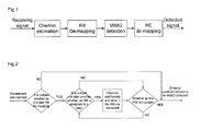
Fig. 1 is a schematic diagram of signal detection according to an embodiment of the present disclosure; and -
Fig. 2 is a schematic diagram of physical RB de-mapping according to an embodiment of the present disclosure. - In practical applications, by taking advantage of the feature that number of paths of output data of MIMO detection is much smaller than that of its input data, valid data and their corresponding channel coefficients may not be extracted immediately after channel estimation is performed, instead, the MIMO detection is performed, then RE de-mapping is performed, thereby the complexity of the RE de-mapping is lowered substantially.
- For example, referring to the operation principle as shown in
Fig. 1 , the following steps may be implemented: - Step 1: Channel estimation is performed to acquire channel coefficients of all antenna pairs.
- Step 2: RB de-mapping is performed.
- It should be noted that the RB de-mapping is an optional operation. Before the RB de-mapping is performed, it may be judged whether to activate the RB de-mapping according to the RBs assigned to a user.
- A preferred judgement method includes: comparing number M of RBs assigned to a user with a predetermined threshold th, and activating the RB de-mapping if the number M of RBs is smaller than the threshold th. The threshold th may be acquired according to different system bandwidth estimation complexities.
- Another preferred judgement method includes determining whether the RB de-mapping is activated according to a dispersion degree of the RBs assigned to the user.
- Certainly, the above two methods may be combined to judge whether to activate the RB de-mapping.
- After that, the RB de-mapping may be performed respectively on the channel coefficients and data.
- If there are valid data of a user in a certain RB, data and their channel coefficients corresponding to all REs in the RB are all outputted so that MIMO detection will be performed.
- Step 3: The MIMO detection is performed.
- According to acquired data and their channel coefficients after the RB de-mapping, an MIMO detected signal corresponding to each RE in the RB is calculated.
- Step 4: RE de-mapping is performed on the MIMO detected signal.
- The RE de-mapping includes: extracting valid data from the MIMO detected signal, i.e., removing a reference signal, a primary synchronization signal, a Physical Broadcasting Channel (PBCH) and the like, and combining together valid data of a user.
- It should be noted that the above channel estimation operation may be implemented by a channel estimation unit, the RB de-mapping operation may be implemented by an RB de-mapping unit, the MIMO detection operation may be implemented by an MIMO detection unit, and the RE de-mapping operation may be implemented by an RE de-mapping unit. The channel estimation unit, the MIMO detection unit and the RE de-mapping unit may be connected in sequence to constitute a signal detection system according to the disclosure. Moreover, the system may further include the RB de-mapping unit connected between the channel estimation unit and the MIMO detection unit. Due to the adding of the RB de-mapping module, the complexity of the RE de-mapping may be further lowered substantially by proper control of the complexity of the MIMO detection. In addition, it is very convenient to perform MIMO detection through vector processing, thus a substantial lowering of the complexity of the RE de-mapping may be acquired at the cost of an increase of the complexity of the MIMO detection.
- Referring to
Fig. 2, Fig. 2 illustrates the implementation process of the RB de-mapping. Firstly, it may be judged whether the RB de-mapping is activated, and if the RB de-mapping is activated, de-mapping processing of channel coefficients and data is performed, otherwise proceed directly to the MIMO detection. For the de-mapping processing of the channel coefficients and data, a method of judging and extracting all RBs one after another is adopted. For example, it is judged one after another whether an RB is assigned to a user, and if the judgement result is Yes, the channel coefficients and data in the RB are extracted, and then it is determined whether all the RBs are judged; otherwise, it is determined directly whether all the RBs are judged. If it is determined that all the RBs are judged, channel coefficients/data to be MIMO detected are outputted so that subsequent MIMO detection will be performed; if not all the RBs are determined, the step for judging one after another whether an RB is assigned to a user is implemented. - After the operations shown in
Fig. 1 and Fig. 2 are completed, comparison results, as shown in Table 1, between cycles according to the disclosure and those according to a commonly-used method are acquired. It is assumed that the vector processor adopts a 32 Multiply-Accumulator (MAC) and the MIMO detection adopts a typical Minimum Mean Square Error MMSE) algorithm, then performing MIMO detection processing on each RE needs four cycles, and the total number of cycles is only 38% of that of the commonly-used method. It can be seen that the disclosure lowers substantially the complexity of the RE de-mapping.Commonly-used method The disclosure MIMO detection (cycle) 320 480 RE de-mapping (cycle) 1800 340 Total (cycle) 2120 820 - In practical applications, in LTE, each Orthogonal Frequency Division Multiplexing (OFDM) symbol in one RB includes 12 REs. 4×2 MIMO two-layer open-loop spatial multiplexing, a system bandwidth of 3 MHz, and an OFDM symbol to be detected being a symbol including a reference signal are taken as an example to explain the specific steps of the disclosure. There are 15 RBs in 3 MHz, and it is assumed that the first 10 RBs are assigned to a user. Then, the following steps may be implemented:
- Step 1: Channel estimation is performed to acquire channel coefficients of all antenna pairs, i.e., 8-path channel coefficients.
- Step 2: RB de-mapping is performed.
- It is assumed that the judgement activation threshold is set to 60% of the system bandwidth, i.e., th=60%*15=9. The number M of RBs assigned to a user meets M=10>th, then the RB de-mapping is activated.
- All the RBs are judged to determine whether an RB is assigned to a user, if it is determined that the RB is assigned to the user, channel coefficients and data are extracted.
- Step 3: MIMO detection is performed.
- The extracted 8-path channel coefficients and 2-path data of the first 10 valid RBs are regarded as input data of the MIMO detection, then 2-path MIMO detected output data of MIMO detection are acquired.
- Step 4: RE de-mapping is performed.
- Valid data are extracted from the 2-path MIMO detected output data, i.e., removing a reference signal, a primary synchronization signal, a PBCH and the like, and combining together valid data of a user.
- To sum up, it can be seen that regardless of the method or the system, by taking full advantage of the feature that number of paths of output data of MIMO detection module is much smaller than that of its input data, the signal detection technique according to the disclosure can lower substantially the complexity of the RE de-mapping through adjusting the sequence of the MIMO detection and the RE de-mapping.
Claims (10)
- A signal detection method, comprising:after channel estimation is completed, performing Multiple-Input Multiple-Output (MIMO) detection, then performing Resource Element (RE) de-mapping.
- The method according to claim 1, wherein after the channel estimation is completed, before the MIMO detection is performed, it is judged whether physical Resource Block (RB) de-mapping is performed.
- The method according to claim 2, wherein the judgement method comprises:comparing number M of RBs assigned to a user with a predetermined threshold th, and activating the RB de-mapping if the number M of RBs is smaller than the threshold th; and/ordetermining, according to a dispersion degree of the RBs assigned to the user, whether to activate the RB de-mapping.
- The method according to claim 3, wherein when the RB de-mapping is performed, de-mapping of channel coefficients and data are processed by judging and extracting all the RBs one after another.
- The method according to any one of claims 1 to 4, wherein the process of the RE de-mapping comprises:extracting valid data from an MIMO detected signal, and combining together valid data of a user.
- A signal detection system, comprising a channel estimation unit, an MIMO detection unit and an RE de-mapping unit, wherein
the MIMO detection unit is configured to perform MIMO detection after channel estimation is completed by the channel estimation unit; and
the RE de-mapping unit is configured to perform RE de-mapping after the MIMO detection is completed by the MIMO detection unit. - The system according to claim 6, wherein the system further comprises an RB de-mapping unit configured to judge whether to perform RB de-mapping after the channel estimation is completed and before the MIMO detection is performed.
- The system according to claim 7, wherein when performing the judgement, the RB de-mapping unit is configured to:compare number M of RBs assigned to a user with a predetermined threshold th, and activate the RB de-mapping if the number M of RBs is smaller than the threshold th; and/ordetermine, according to a dispersion degree of the RBs assigned to the user, whether to activate the RB de-mapping.
- The system according to claim 8, wherein when performing the RB de-mapping, the RB de-mapping unit is configured to process de-mapping of channel coefficients and data by judging and extracting all the RBs one after another.
- The system according to any one of claims 6 to 9, wherein when performing the RE de-mapping, the RE de-mapping unit is configured to:extract valid data from an MIMO detected signal, and combine together valid data of a user.
Applications Claiming Priority (1)
| Application Number | Priority Date | Filing Date | Title |
|---|---|---|---|
| PCT/CN2011/080243 WO2013044453A1 (en) | 2011-09-27 | 2011-09-27 | Signal detection method and system |
Publications (3)
| Publication Number | Publication Date |
|---|---|
| EP2763329A1 true EP2763329A1 (en) | 2014-08-06 |
| EP2763329A4 EP2763329A4 (en) | 2015-05-06 |
| EP2763329B1 EP2763329B1 (en) | 2018-04-25 |
Family
ID=47994122
Family Applications (1)
| Application Number | Title | Priority Date | Filing Date |
|---|---|---|---|
| EP11873478.9A Active EP2763329B1 (en) | 2011-09-27 | 2011-09-27 | Signal detection method and system |
Country Status (2)
| Country | Link |
|---|---|
| EP (1) | EP2763329B1 (en) |
| WO (1) | WO2013044453A1 (en) |
Family Cites Families (4)
| Publication number | Priority date | Publication date | Assignee | Title |
|---|---|---|---|---|
| US8780771B2 (en) * | 2007-02-06 | 2014-07-15 | Qualcomm Incorporated | Cyclic delay diversity and precoding for wireless communication |
| EP2073471A1 (en) * | 2007-12-20 | 2009-06-24 | Sony Corporation | Improved selection criterion for quantized precoded spatial multiplexing MIMO |
| CN102204140A (en) * | 2008-10-31 | 2011-09-28 | 夏普株式会社 | Transmitter apparatus, receiver apparatus and communication system |
| EP2540007B1 (en) * | 2010-02-25 | 2013-12-25 | Sony Corporation | Demapping apparatus and method for reception of data in a multi-carrier broadcast system |
-
2011
- 2011-09-27 EP EP11873478.9A patent/EP2763329B1/en active Active
- 2011-09-27 WO PCT/CN2011/080243 patent/WO2013044453A1/en not_active Ceased
Also Published As
| Publication number | Publication date |
|---|---|
| EP2763329B1 (en) | 2018-04-25 |
| WO2013044453A1 (en) | 2013-04-04 |
| EP2763329A4 (en) | 2015-05-06 |
Similar Documents
| Publication | Publication Date | Title |
|---|---|---|
| US20250080170A1 (en) | Methods, distributed base station system, remote radio unit and base band unit system for handling uplink signals | |
| JP2011239405A5 (en) | ||
| US20150078429A1 (en) | Unified Interference Power Estimation | |
| EP4064760A1 (en) | Device control method and apparatus, storage medium and electronic device | |
| EP4207623A1 (en) | Method for sending and method for receiving demodulation reference signal, and communication apparatus | |
| CN113746509A (en) | Channel information processing method and device | |
| CN103516447B (en) | A kind of multi-antenna signal merging method and network equipment | |
| WO2015066866A1 (en) | Method and device for detecting secondary synchronous signal, computer program and storage medium | |
| CN106470054B (en) | Data processing method and related device and system | |
| CN107302385A (en) | Virtual multi-input, multi-output communication method, apparatus and system | |
| CN103238347B (en) | Power control method and device | |
| EP2763329B1 (en) | Signal detection method and system | |
| CN107276733B (en) | A kind of method, base station and the terminal of the port mapping of determining DMRS | |
| CN103179056A (en) | Method and device for channel estimation | |
| CN110011744B (en) | Port detection method, system and terminal | |
| CN105577252A (en) | Antenna selection method of mobile terminal | |
| CN103947148B (en) | Discrete transmission detecting device and method | |
| CN101860884A (en) | A method and device for channel estimation of same-frequency adjacent cells | |
| EP2829099A1 (en) | Transmission point selection | |
| EP3132582B1 (en) | Distributed base station with frequency domain interface on which signal subspace varies according to frequency bin | |
| CN115714702A (en) | Data processing method and device, electronic equipment and computer storage medium | |
| EP3098997B1 (en) | Data transmission and data receiving detection method, base station, and user equipment | |
| JP6393527B2 (en) | User apparatus and interference reduction method | |
| CN103379500A (en) | Method and apparatus for eliminating co-frequency interference based on dual carrier downlink system | |
| CN104025672A (en) | Apparatus, method, mobile station and digital storage medium |
Legal Events
| Date | Code | Title | Description |
|---|---|---|---|
| PUAI | Public reference made under article 153(3) epc to a published international application that has entered the european phase |
Free format text: ORIGINAL CODE: 0009012 |
|
| 17P | Request for examination filed |
Effective date: 20140422 |
|
| AK | Designated contracting states |
Kind code of ref document: A1 Designated state(s): AL AT BE BG CH CY CZ DE DK EE ES FI FR GB GR HR HU IE IS IT LI LT LU LV MC MK MT NL NO PL PT RO RS SE SI SK SM TR |
|
| DAX | Request for extension of the european patent (deleted) | ||
| RA4 | Supplementary search report drawn up and despatched (corrected) |
Effective date: 20150410 |
|
| RIC1 | Information provided on ipc code assigned before grant |
Ipc: H04B 7/08 20060101AFI20150405BHEP Ipc: H04B 7/04 20060101ALI20150405BHEP |
|
| RAP1 | Party data changed (applicant data changed or rights of an application transferred) |
Owner name: ZTE MICROELECTRONICS TECHNOLOGY CO., LTD |
|
| RAP1 | Party data changed (applicant data changed or rights of an application transferred) |
Owner name: SANECHIPS TECHNOLOGY CO., LTD. |
|
| GRAP | Despatch of communication of intention to grant a patent |
Free format text: ORIGINAL CODE: EPIDOSNIGR1 |
|
| STAA | Information on the status of an ep patent application or granted ep patent |
Free format text: STATUS: GRANT OF PATENT IS INTENDED |
|
| RIC1 | Information provided on ipc code assigned before grant |
Ipc: H04B 7/0413 20170101ALI20171108BHEP Ipc: H04B 7/08 20060101AFI20171108BHEP |
|
| INTG | Intention to grant announced |
Effective date: 20171201 |
|
| GRAA | (expected) grant |
Free format text: ORIGINAL CODE: 0009210 |
|
| GRAS | Grant fee paid |
Free format text: ORIGINAL CODE: EPIDOSNIGR3 |
|
| STAA | Information on the status of an ep patent application or granted ep patent |
Free format text: STATUS: THE PATENT HAS BEEN GRANTED |
|
| AK | Designated contracting states |
Kind code of ref document: B1 Designated state(s): AL AT BE BG CH CY CZ DE DK EE ES FI FR GB GR HR HU IE IS IT LI LT LU LV MC MK MT NL NO PL PT RO RS SE SI SK SM TR |
|
| REG | Reference to a national code |
Ref country code: GB Ref legal event code: FG4D |
|
| REG | Reference to a national code |
Ref country code: CH Ref legal event code: EP |
|
| REG | Reference to a national code |
Ref country code: AT Ref legal event code: REF Ref document number: 993929 Country of ref document: AT Kind code of ref document: T Effective date: 20180515 |
|
| REG | Reference to a national code |
Ref country code: IE Ref legal event code: FG4D |
|
| REG | Reference to a national code |
Ref country code: DE Ref legal event code: R096 Ref document number: 602011047939 Country of ref document: DE |
|
| REG | Reference to a national code |
Ref country code: NL Ref legal event code: MP Effective date: 20180425 |
|
| REG | Reference to a national code |
Ref country code: LT Ref legal event code: MG4D |
|
| REG | Reference to a national code |
Ref country code: FR Ref legal event code: PLFP Year of fee payment: 8 |
|
| PG25 | Lapsed in a contracting state [announced via postgrant information from national office to epo] |
Ref country code: NL Free format text: LAPSE BECAUSE OF FAILURE TO SUBMIT A TRANSLATION OF THE DESCRIPTION OR TO PAY THE FEE WITHIN THE PRESCRIBED TIME-LIMIT Effective date: 20180425 |
|
| PG25 | Lapsed in a contracting state [announced via postgrant information from national office to epo] |
Ref country code: PL Free format text: LAPSE BECAUSE OF FAILURE TO SUBMIT A TRANSLATION OF THE DESCRIPTION OR TO PAY THE FEE WITHIN THE PRESCRIBED TIME-LIMIT Effective date: 20180425 Ref country code: NO Free format text: LAPSE BECAUSE OF FAILURE TO SUBMIT A TRANSLATION OF THE DESCRIPTION OR TO PAY THE FEE WITHIN THE PRESCRIBED TIME-LIMIT Effective date: 20180725 Ref country code: SE Free format text: LAPSE BECAUSE OF FAILURE TO SUBMIT A TRANSLATION OF THE DESCRIPTION OR TO PAY THE FEE WITHIN THE PRESCRIBED TIME-LIMIT Effective date: 20180425 Ref country code: FI Free format text: LAPSE BECAUSE OF FAILURE TO SUBMIT A TRANSLATION OF THE DESCRIPTION OR TO PAY THE FEE WITHIN THE PRESCRIBED TIME-LIMIT Effective date: 20180425 Ref country code: BG Free format text: LAPSE BECAUSE OF FAILURE TO SUBMIT A TRANSLATION OF THE DESCRIPTION OR TO PAY THE FEE WITHIN THE PRESCRIBED TIME-LIMIT Effective date: 20180725 Ref country code: LT Free format text: LAPSE BECAUSE OF FAILURE TO SUBMIT A TRANSLATION OF THE DESCRIPTION OR TO PAY THE FEE WITHIN THE PRESCRIBED TIME-LIMIT Effective date: 20180425 Ref country code: ES Free format text: LAPSE BECAUSE OF FAILURE TO SUBMIT A TRANSLATION OF THE DESCRIPTION OR TO PAY THE FEE WITHIN THE PRESCRIBED TIME-LIMIT Effective date: 20180425 |
|
| PG25 | Lapsed in a contracting state [announced via postgrant information from national office to epo] |
Ref country code: LV Free format text: LAPSE BECAUSE OF FAILURE TO SUBMIT A TRANSLATION OF THE DESCRIPTION OR TO PAY THE FEE WITHIN THE PRESCRIBED TIME-LIMIT Effective date: 20180425 Ref country code: HR Free format text: LAPSE BECAUSE OF FAILURE TO SUBMIT A TRANSLATION OF THE DESCRIPTION OR TO PAY THE FEE WITHIN THE PRESCRIBED TIME-LIMIT Effective date: 20180425 Ref country code: GR Free format text: LAPSE BECAUSE OF FAILURE TO SUBMIT A TRANSLATION OF THE DESCRIPTION OR TO PAY THE FEE WITHIN THE PRESCRIBED TIME-LIMIT Effective date: 20180726 Ref country code: RS Free format text: LAPSE BECAUSE OF FAILURE TO SUBMIT A TRANSLATION OF THE DESCRIPTION OR TO PAY THE FEE WITHIN THE PRESCRIBED TIME-LIMIT Effective date: 20180425 |
|
| REG | Reference to a national code |
Ref country code: AT Ref legal event code: MK05 Ref document number: 993929 Country of ref document: AT Kind code of ref document: T Effective date: 20180425 |
|
| PG25 | Lapsed in a contracting state [announced via postgrant information from national office to epo] |
Ref country code: PT Free format text: LAPSE BECAUSE OF FAILURE TO SUBMIT A TRANSLATION OF THE DESCRIPTION OR TO PAY THE FEE WITHIN THE PRESCRIBED TIME-LIMIT Effective date: 20180827 |
|
| REG | Reference to a national code |
Ref country code: DE Ref legal event code: R097 Ref document number: 602011047939 Country of ref document: DE |
|
| PG25 | Lapsed in a contracting state [announced via postgrant information from national office to epo] |
Ref country code: AT Free format text: LAPSE BECAUSE OF FAILURE TO SUBMIT A TRANSLATION OF THE DESCRIPTION OR TO PAY THE FEE WITHIN THE PRESCRIBED TIME-LIMIT Effective date: 20180425 Ref country code: DK Free format text: LAPSE BECAUSE OF FAILURE TO SUBMIT A TRANSLATION OF THE DESCRIPTION OR TO PAY THE FEE WITHIN THE PRESCRIBED TIME-LIMIT Effective date: 20180425 Ref country code: EE Free format text: LAPSE BECAUSE OF FAILURE TO SUBMIT A TRANSLATION OF THE DESCRIPTION OR TO PAY THE FEE WITHIN THE PRESCRIBED TIME-LIMIT Effective date: 20180425 Ref country code: RO Free format text: LAPSE BECAUSE OF FAILURE TO SUBMIT A TRANSLATION OF THE DESCRIPTION OR TO PAY THE FEE WITHIN THE PRESCRIBED TIME-LIMIT Effective date: 20180425 Ref country code: CZ Free format text: LAPSE BECAUSE OF FAILURE TO SUBMIT A TRANSLATION OF THE DESCRIPTION OR TO PAY THE FEE WITHIN THE PRESCRIBED TIME-LIMIT Effective date: 20180425 Ref country code: SK Free format text: LAPSE BECAUSE OF FAILURE TO SUBMIT A TRANSLATION OF THE DESCRIPTION OR TO PAY THE FEE WITHIN THE PRESCRIBED TIME-LIMIT Effective date: 20180425 |
|
| PG25 | Lapsed in a contracting state [announced via postgrant information from national office to epo] |
Ref country code: SM Free format text: LAPSE BECAUSE OF FAILURE TO SUBMIT A TRANSLATION OF THE DESCRIPTION OR TO PAY THE FEE WITHIN THE PRESCRIBED TIME-LIMIT Effective date: 20180425 Ref country code: IT Free format text: LAPSE BECAUSE OF FAILURE TO SUBMIT A TRANSLATION OF THE DESCRIPTION OR TO PAY THE FEE WITHIN THE PRESCRIBED TIME-LIMIT Effective date: 20180425 |
|
| PLBE | No opposition filed within time limit |
Free format text: ORIGINAL CODE: 0009261 |
|
| STAA | Information on the status of an ep patent application or granted ep patent |
Free format text: STATUS: NO OPPOSITION FILED WITHIN TIME LIMIT |
|
| REG | Reference to a national code |
Ref country code: DE Ref legal event code: R119 Ref document number: 602011047939 Country of ref document: DE |
|
| 26N | No opposition filed |
Effective date: 20190128 |
|
| PG25 | Lapsed in a contracting state [announced via postgrant information from national office to epo] |
Ref country code: MC Free format text: LAPSE BECAUSE OF FAILURE TO SUBMIT A TRANSLATION OF THE DESCRIPTION OR TO PAY THE FEE WITHIN THE PRESCRIBED TIME-LIMIT Effective date: 20180425 |
|
| REG | Reference to a national code |
Ref country code: CH Ref legal event code: PL |
|
| GBPC | Gb: european patent ceased through non-payment of renewal fee |
Effective date: 20180927 |
|
| PG25 | Lapsed in a contracting state [announced via postgrant information from national office to epo] |
Ref country code: SI Free format text: LAPSE BECAUSE OF FAILURE TO SUBMIT A TRANSLATION OF THE DESCRIPTION OR TO PAY THE FEE WITHIN THE PRESCRIBED TIME-LIMIT Effective date: 20180425 |
|
| REG | Reference to a national code |
Ref country code: BE Ref legal event code: MM Effective date: 20180930 |
|
| REG | Reference to a national code |
Ref country code: IE Ref legal event code: MM4A |
|
| PG25 | Lapsed in a contracting state [announced via postgrant information from national office to epo] |
Ref country code: LU Free format text: LAPSE BECAUSE OF NON-PAYMENT OF DUE FEES Effective date: 20180927 |
|
| PG25 | Lapsed in a contracting state [announced via postgrant information from national office to epo] |
Ref country code: DE Free format text: LAPSE BECAUSE OF NON-PAYMENT OF DUE FEES Effective date: 20190402 Ref country code: IE Free format text: LAPSE BECAUSE OF NON-PAYMENT OF DUE FEES Effective date: 20180927 |
|
| PG25 | Lapsed in a contracting state [announced via postgrant information from national office to epo] |
Ref country code: BE Free format text: LAPSE BECAUSE OF NON-PAYMENT OF DUE FEES Effective date: 20180930 Ref country code: LI Free format text: LAPSE BECAUSE OF NON-PAYMENT OF DUE FEES Effective date: 20180930 Ref country code: CH Free format text: LAPSE BECAUSE OF NON-PAYMENT OF DUE FEES Effective date: 20180930 |
|
| PG25 | Lapsed in a contracting state [announced via postgrant information from national office to epo] |
Ref country code: GB Free format text: LAPSE BECAUSE OF NON-PAYMENT OF DUE FEES Effective date: 20180927 |
|
| PG25 | Lapsed in a contracting state [announced via postgrant information from national office to epo] |
Ref country code: AL Free format text: LAPSE BECAUSE OF FAILURE TO SUBMIT A TRANSLATION OF THE DESCRIPTION OR TO PAY THE FEE WITHIN THE PRESCRIBED TIME-LIMIT Effective date: 20180425 |
|
| PG25 | Lapsed in a contracting state [announced via postgrant information from national office to epo] |
Ref country code: MT Free format text: LAPSE BECAUSE OF NON-PAYMENT OF DUE FEES Effective date: 20180927 |
|
| PG25 | Lapsed in a contracting state [announced via postgrant information from national office to epo] |
Ref country code: TR Free format text: LAPSE BECAUSE OF FAILURE TO SUBMIT A TRANSLATION OF THE DESCRIPTION OR TO PAY THE FEE WITHIN THE PRESCRIBED TIME-LIMIT Effective date: 20180425 |
|
| PG25 | Lapsed in a contracting state [announced via postgrant information from national office to epo] |
Ref country code: HU Free format text: LAPSE BECAUSE OF FAILURE TO SUBMIT A TRANSLATION OF THE DESCRIPTION OR TO PAY THE FEE WITHIN THE PRESCRIBED TIME-LIMIT; INVALID AB INITIO Effective date: 20110927 |
|
| PG25 | Lapsed in a contracting state [announced via postgrant information from national office to epo] |
Ref country code: CY Free format text: LAPSE BECAUSE OF FAILURE TO SUBMIT A TRANSLATION OF THE DESCRIPTION OR TO PAY THE FEE WITHIN THE PRESCRIBED TIME-LIMIT Effective date: 20180425 Ref country code: MK Free format text: LAPSE BECAUSE OF NON-PAYMENT OF DUE FEES Effective date: 20180425 |
|
| PG25 | Lapsed in a contracting state [announced via postgrant information from national office to epo] |
Ref country code: IS Free format text: LAPSE BECAUSE OF FAILURE TO SUBMIT A TRANSLATION OF THE DESCRIPTION OR TO PAY THE FEE WITHIN THE PRESCRIBED TIME-LIMIT Effective date: 20180825 |
|
| PGFP | Annual fee paid to national office [announced via postgrant information from national office to epo] |
Ref country code: FR Payment date: 20250808 Year of fee payment: 15 |