EP2763291A1 - Motor drive device and vehicle - Google Patents
Motor drive device and vehicle Download PDFInfo
- Publication number
- EP2763291A1 EP2763291A1 EP11873390.6A EP11873390A EP2763291A1 EP 2763291 A1 EP2763291 A1 EP 2763291A1 EP 11873390 A EP11873390 A EP 11873390A EP 2763291 A1 EP2763291 A1 EP 2763291A1
- Authority
- EP
- European Patent Office
- Prior art keywords
- case
- motor
- case portion
- power conversion
- winding switching
- Prior art date
- Legal status (The legal status is an assumption and is not a legal conclusion. Google has not performed a legal analysis and makes no representation as to the accuracy of the status listed.)
- Withdrawn
Links
Images


Classifications
-
- H—ELECTRICITY
- H02—GENERATION; CONVERSION OR DISTRIBUTION OF ELECTRIC POWER
- H02K—DYNAMO-ELECTRIC MACHINES
- H02K3/00—Details of windings
-
- H—ELECTRICITY
- H02—GENERATION; CONVERSION OR DISTRIBUTION OF ELECTRIC POWER
- H02K—DYNAMO-ELECTRIC MACHINES
- H02K5/00—Casings; Enclosures; Supports
- H02K5/04—Casings or enclosures characterised by the shape, form or construction thereof
- H02K5/20—Casings or enclosures characterised by the shape, form or construction thereof with channels or ducts for flow of cooling medium
-
- B—PERFORMING OPERATIONS; TRANSPORTING
- B60—VEHICLES IN GENERAL
- B60L—PROPULSION OF ELECTRICALLY-PROPELLED VEHICLES; SUPPLYING ELECTRIC POWER FOR AUXILIARY EQUIPMENT OF ELECTRICALLY-PROPELLED VEHICLES; ELECTRODYNAMIC BRAKE SYSTEMS FOR VEHICLES IN GENERAL; MAGNETIC SUSPENSION OR LEVITATION FOR VEHICLES; MONITORING OPERATING VARIABLES OF ELECTRICALLY-PROPELLED VEHICLES; ELECTRIC SAFETY DEVICES FOR ELECTRICALLY-PROPELLED VEHICLES
- B60L50/00—Electric propulsion with power supplied within the vehicle
- B60L50/50—Electric propulsion with power supplied within the vehicle using propulsion power supplied by batteries or fuel cells
-
- H—ELECTRICITY
- H02—GENERATION; CONVERSION OR DISTRIBUTION OF ELECTRIC POWER
- H02K—DYNAMO-ELECTRIC MACHINES
- H02K11/00—Structural association of dynamo-electric machines with electric components or with devices for shielding, monitoring or protection
- H02K11/30—Structural association with control circuits or drive circuits
- H02K11/33—Drive circuits, e.g. power electronics
-
- H—ELECTRICITY
- H02—GENERATION; CONVERSION OR DISTRIBUTION OF ELECTRIC POWER
- H02K—DYNAMO-ELECTRIC MACHINES
- H02K3/00—Details of windings
- H02K3/46—Fastening of windings on the stator or rotor structure
- H02K3/50—Fastening of winding heads, equalising connectors, or connections thereto
-
- H—ELECTRICITY
- H02—GENERATION; CONVERSION OR DISTRIBUTION OF ELECTRIC POWER
- H02K—DYNAMO-ELECTRIC MACHINES
- H02K5/00—Casings; Enclosures; Supports
- H02K5/04—Casings or enclosures characterised by the shape, form or construction thereof
-
- H—ELECTRICITY
- H02—GENERATION; CONVERSION OR DISTRIBUTION OF ELECTRIC POWER
- H02K—DYNAMO-ELECTRIC MACHINES
- H02K5/00—Casings; Enclosures; Supports
- H02K5/04—Casings or enclosures characterised by the shape, form or construction thereof
- H02K5/15—Mounting arrangements for bearing-shields or end plates
-
- H—ELECTRICITY
- H02—GENERATION; CONVERSION OR DISTRIBUTION OF ELECTRIC POWER
- H02K—DYNAMO-ELECTRIC MACHINES
- H02K5/00—Casings; Enclosures; Supports
- H02K5/04—Casings or enclosures characterised by the shape, form or construction thereof
- H02K5/20—Casings or enclosures characterised by the shape, form or construction thereof with channels or ducts for flow of cooling medium
- H02K5/203—Casings or enclosures characterised by the shape, form or construction thereof with channels or ducts for flow of cooling medium specially adapted for liquids, e.g. cooling jackets
-
- H—ELECTRICITY
- H02—GENERATION; CONVERSION OR DISTRIBUTION OF ELECTRIC POWER
- H02K—DYNAMO-ELECTRIC MACHINES
- H02K5/00—Casings; Enclosures; Supports
- H02K5/04—Casings or enclosures characterised by the shape, form or construction thereof
- H02K5/22—Auxiliary parts of casings not covered by groups H02K5/06-H02K5/20, e.g. shaped to form connection boxes or terminal boxes
- H02K5/225—Terminal boxes or connection arrangements
-
- H—ELECTRICITY
- H02—GENERATION; CONVERSION OR DISTRIBUTION OF ELECTRIC POWER
- H02K—DYNAMO-ELECTRIC MACHINES
- H02K9/00—Arrangements for cooling or ventilating
-
- H—ELECTRICITY
- H05—ELECTRIC TECHNIQUES NOT OTHERWISE PROVIDED FOR
- H05K—PRINTED CIRCUITS; CASINGS OR CONSTRUCTIONAL DETAILS OF ELECTRIC APPARATUS; MANUFACTURE OF ASSEMBLAGES OF ELECTRICAL COMPONENTS
- H05K7/00—Constructional details common to different types of electric apparatus
- H05K7/20—Modifications to facilitate cooling, ventilating, or heating
- H05K7/2089—Modifications to facilitate cooling, ventilating, or heating for power electronics, e.g. for inverters for controlling motor
-
- Y—GENERAL TAGGING OF NEW TECHNOLOGICAL DEVELOPMENTS; GENERAL TAGGING OF CROSS-SECTIONAL TECHNOLOGIES SPANNING OVER SEVERAL SECTIONS OF THE IPC; TECHNICAL SUBJECTS COVERED BY FORMER USPC CROSS-REFERENCE ART COLLECTIONS [XRACs] AND DIGESTS
- Y02—TECHNOLOGIES OR APPLICATIONS FOR MITIGATION OR ADAPTATION AGAINST CLIMATE CHANGE
- Y02T—CLIMATE CHANGE MITIGATION TECHNOLOGIES RELATED TO TRANSPORTATION
- Y02T10/00—Road transport of goods or passengers
- Y02T10/60—Other road transportation technologies with climate change mitigation effect
- Y02T10/70—Energy storage systems for electromobility, e.g. batteries
Definitions
- the present invention relates to a motor drive device and a vehicle, and more particularly, it relates to a motor drive device and a vehicle each including a motor including a high-speed drive winding and a low-speed drive winding.
- a motor drive device including a motor including a high-speed drive winding and a low-speed drive winding is known.
- Such a motor drive device is disclosed in Japanese Patent Laying-Open No. 2010-17055 , for example.
- a motor drive device including a motor including a high-speed drive winding and a low-speed drive winding, a winding switching portion switching the connection states of the two windings of the motor, and an inverter (power conversion portion) connected to the motor.
- the motor, the winding switching portion, and the power conversion portion are generally housed in separate case portions and placed separately.
- Patent Document 1 Japanese Patent Laying-Open No. 2010-17055
- the motor, the winding switching portion, and the power conversion portion are housed in the separate case portions and placed separately, and hence there may be dead spaces between the case portions housing the motor, the winding switching portion, and the power conversion portion. In this case, there is such a problem that it is difficult to save space.
- the present invention has been proposed in order to solve the aforementioned problem, and an object of the present invention is to provide a motor drive device and a vehicle each capable of saving space.
- a motor drive device includes a motor including a high-speed drive winding and a low-speed drive winding, a winding switching portion switching the connection states of the high-speed drive winding and the low-speed drive winding of the motor, a power conversion portion connected to the motor, and a plurality of case portions housing at least the motor, the winding switching portion, and the power conversion portion, while the plurality of case portions are coupled to each other.
- the motor drive device is provided with the plurality of case portions housing at least the motor, the winding switching portion, and the power conversion portion, and the plurality of case portions are coupled to each other.
- the plurality of case portions housing at least the motor, the winding switching portion, and the power conversion portion can be coupled to each other to be integrated, and hence formation of dead spaces between the case portions housing at least the motor, the winding switching portion, and the power conversion portion can be suppressed. Consequently, space can be saved.
- a vehicle includes a vehicle body portion and a motor drive portion provided inside the vehicle body portion, while the motor drive portion includes a motor including a high-speed drive winding and a low-speed drive winding, a winding switching portion switching the connection states of the high-speed drive winding and the low-speed drive winding of the motor, a power conversion portion connected to the motor, and a plurality of case portions housing at least the motor, the winding switching portion, and the power conversion portion, and the plurality of case portions are coupled to each other.
- the vehicle according to the second aspect of the present invention is provided with the plurality of case portions housing at least the motor, the winding switching portion, and the power conversion portion of the motor drive portion, and the plurality of case portions are coupled to each other.
- the plurality of case portions housing at least the motor, the winding switching portion, and the power conversion portion of the motor drive portion can be coupled to each other to be integrated, and hence formation of dead spaces between the case portions housing at least the motor, the winding switching portion, and the power conversion portion of the motor drive portion can be suppressed. Consequently, the vehicle in which a space for the motor drive portion can be saved can be provided. This advantageous effect is effectively exerted particularly in the vehicle in which it is necessary to arrange a large number of members in a limited arrangement space.
- Fig. 1 The structure of a vehicle 100 according to the embodiment of the present invention is now described with reference to Fig. 1 .
- the structure shown in Fig. 1 is a representative example showing the structure of a vehicle including a winding switching type motor drive portion, and the present invention is not restricted to this.
- the vehicle 100 includes a vehicle body portion 101, a motor drive portion 10 provided inside the vehicle body portion 101, and a battery portion 20 connected to the motor drive portion 10.
- the motor drive portion 10 is an example of the "motor drive device" in the present invention.
- the motor drive portion 10 is configured to include an inverter portion 1, a smoothing capacitor 2, a motor 3, a winding switching portion 4, a control portion 5, and a power supply portion 6.
- the inverter portion 1 is an example of the "power conversion portion" in the present invention.
- the inverter portion 1 is configured to convert direct-current power input from the battery portion 20 into three-phase (U-phase, V-phase, and W-phase) alternating-current power and output the three-phase alternating-current power to the motor 3.
- the inverter portion 1 has direct-current input terminals TP1 and TN1 connected to the battery portion 20 and alternating-current output terminals TU1, TV1, and TW1 connected to the motor 3.
- the direct-current input terminals TP1 and TN1 of the inverter portion 1 are connected with terminals TP2 and TN2 of the smoothing capacitor 2, respectively.
- This smoothing capacitor 2 is provided to smooth the direct-current power input from the battery portion 20.
- the inverter portion 1 is configured to include six switch elements Q1, Q2, Q3, Q4, Q5, and Q6 for power conversion.
- the switch elements Q1 and Q2 are configured to perform U-phase power conversion.
- the switch elements Q3 and Q4 are configured to perform V-phase power conversion.
- the switch elements Q5 and Q6 are configured to perform W-phase power conversion.
- the switch elements Q1 to Q6 each are made of a SiC semiconductor.
- the motor 3 is configured to be driven in correspondence to three-phase alternating-current power supplied from the inverter portion 1.
- the motor 3 is configured to include a three-phase winding 3a for high-speed drive and a three-phase winding 3b for low-speed drive.
- the windings 3a and 3b are examples of the "high-speed drive winding" and the "low-speed drive winding", respectively.
- the windings 3a and 3b are electrically connected in series.
- Terminals TU2, TV2, and TW2 of three phases (U-phase, V-phase, and W-phase) on a first side of the winding 3a are connected to the inverter portion 1.
- Terminals TU3, TV3, and TW3 of the three phases on a second side of the winding 3a and a first side of the winding 3b are connected to a diode bridge DB1 of the winding switching portion 4 described later.
- Terminals TU4, TV4, and TW4 on a second side of the winding 3b are connected to a diode bridge DB2 of the winding switching portion 4 described later.
- the winding switching portion 4 has a function of switching the connection states of the windings 3a and 3b of the motor 3.
- the winding switching portion 4 is configured to include a high-speed winding switch SW1 to short the terminals TU3, TV3, and TW3 of the motor 3 and a low-speed winding switch SW2 to short the terminals TU4, TV4, and TW4 of the motor 3.
- the high-speed winding switch SW1 and the low-speed winding switch SW2 are examples of the "switch element" in the present invention.
- the high-speed winding switch SW1 and the low-speed winding switch SW2 each are made of a SiC semiconductor.
- the winding switching portion 4 is configured to include the diode bridge DB1 having terminals TU5, TV5, and TW5 connected to the terminals TU3, TV3, and TW3 of the motor 3 and a capacitor C1 configured to protect the winding 3a of the motor 3.
- the high-speed winding switch SW1, the diode bridge DB1, the capacitor C1, and the smoothing capacitor 2 are electrically connected to each other in parallel.
- the winding switching portion 4 is configured to include the diode bridge DB2 having terminals TU6, TV6, and TW6 connected to the terminals TU4, TV4, and TW4 of the motor 3 and a capacitor C2 configured to protect the winding 3b of the motor 3.
- the low-speed winding switch SW2, the diode bridge DB2, the capacitor C2, and the smoothing capacitor 2 are electrically connected to each other in parallel.
- the diode bridge DB1 is constituted by six diodes D11, D12, D13, D14, D15, and D16 configured to rectify three-phase (U-phase, V-phase, and W-phase) alternating current output from the terminals TU3, TV3, and TW3 of the motor 3.
- the diodes D11 and D12 are configured to rectify U-phase alternating current.
- the diodes D13 and D14 are configured to rectify V-phase alternating current.
- the diodes D15 and D16 are configured to rectify W-phase alternating current.
- Two diodes D17 and D18 are provided on the direct-current output side of the diode bridge DB1.
- the diode bridge DB2 is constituted by six diodes D21, D22, D23, D24, D25, and D26 configured to rectify three-phase (U-phase, V-phase, and W-phase) alternating current output from the terminals TU4, TV4, and TW4 of the motor 3.
- the diodes D21 and D22 are configured to rectify U-phase alternating current.
- the diodes D23 and D24 are configured to rectify V-phase alternating current.
- the diodes D25 and D26 are configured to rectify W-phase alternating current.
- Two diodes D27 and D28 are provided on the direct-current output side of the diode bridge DB2.
- the control portion 5 is configured to control the inverter portion 1 and the winding switching portion 4 by outputting control signals (an inverter control signal, a high-speed winding switching control signal, and a low-speed winding switching control signal) to the inverter portion 1 and the winding switching portion 4.
- the power supply portion 6 is configured to supply power (gate power for the inverter) for operating the switch elements Q1 to Q6 of the inverter portion 1 and power (gate power for high-speed winding switching and gate power for low-speed winding switching) for operating the high-speed winding switch SW1 and the low-speed winding switch SW2 of the winding switching portion 4 to the inverter portion 1 and the winding switching portion 4, respectively.
- the motor drive portion 10 includes a first case portion 11 housing the motor 3, a second case portion 12 housing the inverter portion 1 and the winding switching portion 4, a third case portion 13 housing the smoothing capacitor 2, the control portion 5, and the power supply portion 6, and a fourth case portion 14 arranged between the first case portion 11 and the second case portion 12.
- the first case portion 11, the fourth case portion 14, the second case portion 12, and the third case portion 13 are made of metal such as aluminum.
- the first case portion 11, the second case portion 12, the third case portion 13, and the fourth case portion 14 are examples of the "case portion" in the present invention.
- the first case portion 11, the fourth case portion 14, the second case portion 12, and the third case portion 13 are arranged in this order along the extensional direction (the axial direction (direction A ) of the motor 3) of a rotating shaft 31 of the motor 3 described later. As shown in Figs. 3 and 4 , the first case portion 11, the fourth case portion 14, the second case portion 12, and the third case portion 13 are formed in a cylindrical shape extending along the direction A . The first case portion 11, the fourth case portion 14, the second case portion 12, and the third case portion 13 formed in the cylindrical shape have outer diameters substantially equal to each other.
- the first case portion 11, the fourth case portion 14, the second case portion 12, and the third case portion 13 are fastened to each other in the direction A with hexagon socket screws 41, 42, and 43 to be coupled to each other, as shown in Figs. 2 to 4 .
- the first case portion 11 and the fourth case portion 14 are fastened to each other with the hexagon socket screws 41 to be coupled to each other, as shown in Figs. 3 and 4 .
- the fourth case portion 14 and the second case portion 12 are fastened to each other with the hexagon socket screws 42 to be coupled to each other.
- the second case portion 12 and the third case portion 13 are fastened to each other with the hexagon socket screws 43 to be coupled to each other.
- the hexagon socket screws 41 to 43 are examples of the "fastening member" in the present invention.
- a disc-shaped first lid 15 configured to seal the third case portion 13 is provided on the side (side along arrow A1) of the third case portion 13 opposite to the first case portion 11, the second case portion 12, and the fourth case portion 14.
- Three openable and closable second lids 16 in a substantially rectangular shape configured to cover openings 141c and 141d of the fourth case portion 14 described later are provided in the fourth case portion 14.
- the third case portion 13 and the first lid 15 are fastened to each other with screw members 44 to be coupled to each other.
- the fourth case portion 14 and the second lids 16 are fastened to each other with screw members 45 to be coupled to each other.
- portions of the first case portion 11, the fourth case portion 14, the second case portion 12, and the third case portion 13 coupled to each other, a portion between the third case portion 13 and the first lid 15, and portions between the fourth case portion 14 and the second lids 16 are sealed with sealing members 50 formed by applying a liquid sealing agent having a waterproof function and drying the same.
- the first case portion 11 has a side surface portion 111 in a cylindrical shape extending in the direction A (the axial direction of the motor 3) and a bottom surface portion 112 provided on an end of the side surface portion 111 along arrow A2.
- screw holes 111a into which the hexagon socket screws 41 (see Figs. 3 and 4 ) configured to screw the first case portion 11 and the fourth case portion 14 to each other are screwed are provided in the side surface portion 111.
- the screw holes 111a are provided to extend along arrow A2 from an end face of the side surface portion 111 along arrow A1.
- a plurality of (five in this embodiment) screw holes 111a are provided at intervals along a circumferential direction to correspond to a plurality of (five in this embodiment) screw insertion holes 141a (see Fig. 23 ) provided in a side surface portion 141 of the fourth case portion 14 described later, as viewed in the axial direction of the motor 3.
- a breather valve (not shown) configured to suppress damage of the first case portion 11 resulting from excessively increased pressure when pressure in the first case portion 11 is excessively increased due to an increase in temperature or the like is provided in the side surface portion 111.
- the motor 3 housed in the first case portion includes the rotating shaft 31, a rotor core 32, and a stator core 33.
- the rotating shaft 31 is provided to pass through the bottom surface portion 112 in the vicinity of a central portion of the motor 3 and extend in the direction A .
- the rotor core 32 is provided to surround the rotating shaft 31.
- the stator core 33 is arranged to be opposed to the outer periphery of the rotor core 32.
- a plurality of slots 34 are provided on the inner peripheral side of the stator core 33.
- the winding 3a for high-speed drive and the winding 3b for low-speed drive are wound by lap winding or the like and are housed in the plurality of slots 34.
- connection wires 62 having nine connection terminal portions 61 corresponding to the terminals TU2, TV2, TW2, TU3, TV3, TW3, TU4, TV4, and TW4 (see Fig. 1 ) of the windings 3a and 3b.
- These nine connection wires 62 are provided to protrude from an end face of the first case portion 11 along arrow A1 and extend in the direction A .
- a first cooling pipe 113 into which liquid coolant for cooling the motor 3 flows is provided in the first case portion 11, as shown in Fig. 8 .
- a first end (an end on a side from which the liquid coolant flows in) and a second end (an end on a side of which the liquid coolant flows out) of this first cooling pipe 113 are provided to protrude outward from a surface along arrow C2 in the vicinity of an end of the side surface portion 111 along arrow A1.
- the first cooling pipe 113 is an example of the "first cooling portion" in the present invention.
- the first cooling pipe 113 is provided over the entire inner portion of the side surface portion 111 to circumferentially surround a space (a space in which the motor 3 is housed) inside the side surface portion 111.
- the first cooling pipe 113 is formed to have a plurality of linear portions extending from the vicinity of the end along arrow A1 to the vicinity of an end along arrow A2 in the direction A inside the side surface portion 111.
- the plurality of linear portions extending in the direction A are alternately bent in a U shape at the end along arrow A1 and the end along arrow A2 to be connected to each other.
- a series of flow paths into which the liquid coolant flows is formed from the first end of the first cooling pipe 113 to the second end thereof.
- the second case portion 12 has a side surface portion 121 in a cylindrical shape extending in the direction A (the axial direction of the motor 3) and a disc-shaped first partition wall 122 extending along a plane orthogonal to the direction A (along a direction B and a direction C).
- the first partition wall 122 is arranged on an end of the side surface portion 121 along arrow A2.
- screw insertion holes 121a into which the hexagon socket screws 42 (see Figs. 3 and 4 ) configured to screw the second case portion 12 and the fourth case portion 14 to each other are inserted are provided in the side surface portion 121.
- the screw insertion holes 121a are provided to pass through the side surface portion 121 in the direction A .
- a plurality of (seven in this embodiment) screw insertion holes 121a are provided at intervals along the circumferential direction to correspond to a plurality of (seven in this embodiment) screw holes 141b (see Fig. 23 ) provided in the side surface portion 141 of the fourth case portion 14 described later, as viewed in the axial direction of the motor 3.
- screw holes 121b into which the hexagon socket screws 43 (see Figs. 3 and 4 ) configured to screw the second case portion 12 and the third case portion 13 to each other are screwed are provided in the side surface portion 121.
- the screw holes 121b are provided to extend along arrow A2 from an end face of the side surface portion 121 along arrow A1.
- a plurality of (six in this embodiment) screw holes 121b are provided at intervals along the circumferential direction to correspond to a plurality of (six in this embodiment) screw insertion holes 131a (see Figs. 17 and 18 ) provided in a side surface portion 131 of the third case portion 13 described later, as viewed in the axial direction of the motor 3.
- a breather valve (not shown) configured to suppress damage of the second case portion 12 and electronic components placed therein resulting from excessively increased pressure when pressure in the second case portion 12 is excessively increased due to an increase in temperature or the like is provided in the side surface portion 121.
- the first partition wall 122 is provided to isolate the winding switching portion 4 and the inverter portion 1 from each other in the second case portion 12.
- the inverter portion 1 is formed by arranging an inverter module 1a mounted with the electronic component including the switch elements Q1 to Q6 (see Fig. 1 ) in a wiring substrate on a surface of the first partition wall 122 along arrow A1, as shown in Figs. 9 and 11 .
- the winding switching portion 4 is formed by arranging a winding switching module 4a mounted with the electronic component including the high-speed winding switch SW1 and the low-speed winding switch SW2 (see Fig.
- the inverter portion 1 is arranged in a region opposite to (along arrow A1) the motor 3 with respect to the first partition wall 122 of the second case portion 12.
- the winding switching portion 4 is arranged in a region opposite to (along arrow A2) the inverter portion 1 with respect to the first partition wall 122 of the second case portion 12.
- an insulating heat radiation sheet may be provided in a portion between the switch elements Q1 to Q6 of the inverter module 1a and the surface of the first partition wall 122 along arrow A1.
- connection terminal portions 63 corresponding to the terminals TU1, TV1, and TW1 (see Fig. 1 ) of the inverter portion 1 are provided in the inverter module 1a. These three connection terminal portions 63 are provided to protrude from an end face of the inverter module 1a along arrow C1.
- a pair of connection terminal portions 64 corresponding to the terminals TP1 and TN1 (see Fig. 1 ) of the inverter portion 1 are arranged adjacent to the inverter module 1a on the surface of the first partition wall 122 along arrow A1.
- connection terminal portions 64 each have a portion extending in the axial direction (direction A ) and are formed in a U shape such that a first end side and a second end side thereof extend in the direction C.
- portions (long portions extending in the direction C on a side along arrow A2) of the connection terminal portions 64 on the first end side are arranged on the surface of the first partition wall 122 along arrow A1.
- portions (short portions extending in the direction C on the side along arrow A1) of the connection terminal portions 64 on the second end side are configured to be electrically connected to plate-like connection terminal portions 66, described later, of the smoothing capacitor 2 housed in the third case portion 13 by screws.
- connection terminal portions 65 corresponding to the terminals TU5, TV5, TW5, TU6, TV6, and TW6 (see Fig. 1 ) of the winding switching portion 4 are provided in the winding switching module 4a.
- Three of these six connection terminal portions 65 are arranged on the side along arrow B1 of a surface along arrow A2 of the winding switching module 4a, and the remaining three are arranged on the side along arrow B2 of the surface along arrow A2 of the winding switching module 4a.
- connection terminal portions 65 each are formed in an L shape having a portion extending in the direction A and a portion extending in the direction B. These portions of the connection terminal portions 65 extending in the direction B are arranged on a surface of the winding switching module 4a along arrow A2. As shown in Fig. 24 , the portions of the connection terminal portions 65 extending in the direction A are configured to be electrically connected to the connection terminal portions 61 corresponding to the terminals TU3, TV3, TW3, TU4, TV4, and TW4 (see Fig. 1 ) of the motor 3 by screws.
- a second cooling pipe 123 configured to cool the inverter module 1a (inverter portion 1) and the winding switching module 4a (winding switching portion 4) arranged on the surfaces of the first partition wall 122 is provided in the second case portion 12, as shown in Figs. 9 to 14 .
- a first end (an end on a side from which the liquid coolant flows in) and a second end (an end on a side of which the liquid coolant flows out) of this second cooling pipe 123 are provided to protrude outward from a surface along arrow B2 in the vicinity of a central portion of the side surface portion 121 in the direction C.
- the second cooling pipe 123 is an example of the "second cooling portion" in the present invention.
- the second cooling pipe 123 is formed to have a U-shaped portion extending from an end along arrow B2 to the vicinity of an end along arrow B1 inside the first partition wall 122.
- a series of flow paths into which the liquid coolant flows is formed from the first end of the second cooling pipe 123 to the second end thereof.
- the first end of the second cooling pipe 123 of the second case portion and the second end of the first cooling pipe 113 of the first case portion 11 are connected to each other through a coupling portion 70 including a tube or the like.
- the second cooling pipe 123 is provided to overlap with the switch elements Q1 to Q6 (see Fig. 1 ) of the inverter portion 1 mounted in the inverter module 1a, as viewed in the axial direction of the motor 3.
- the second cooling pipe 123 is provided to overlap with the high-speed winding switch SW1 and the low-speed winding switch SW2 of the winding switching portion 4 mounted in the winding switching module 4a, as viewed in the axial direction of the motor 3.
- the switch elements Q1 to Q6 each are illustrated in a rectangular shape shown by a one-dot chain line.
- the high-speed winding switch SW1 and the low-speed winding switch SW2 each are illustrated in a rectangular shape shown by a two-dot chain line.
- three first holes 122a configured to allow wires connected to the inverter portion 1 of the inverter module 1a and the winding switching portion 4 of the winding switching module 4a to pass through are provided in the first partition wall 122.
- one first hole 122a provided in the vicinity of an end of the first partition wall 122 along arrow C1 is provided to allow connection terminal portions 69 (see Fig. 24 ), described later, connected to the connection terminal portion 63 of the inverter portion 1 to pass through when the first case portion 11, the fourth case portion 14, and the second case portion 12 are coupled to each other.
- Two first holes 122a provided in the vicinity of an end of the first partition wall 122 along arrow B1 are provided to allow wires (not shown) or the like configured to transmit the control signals from the control portion 5 to the inverter portion 1 and the winding switching portion 4 to pass through.
- two recess portions 122b are provided in the surface of the first partition wall 122 along arrow A2.
- the two capacitor modules 4b corresponding to the capacitors C1 and C2 (see Fig. 1 ) connected to the high-speed winding switch SW1 and the low-speed winding switch SW2 of the winding switching portion 4 are arranged in these two recess portions 122b.
- the third case portion 13 has the side surface portion 131 in a cylindrical shape extending in the direction A (the axial direction of the motor 3) and a disc-shaped second partition wall 132 extending along the plane orthogonal to the direction A (along the direction B and the direction C). As shown in Figs. 19 and 20 , the second partition wall 132 planarly extends in the direction B and the direction C inside the side surface portion 131.
- the screw insertion holes 131a into which the hexagon socket screws 43 (see Figs. 3 and 4 ) configured to screw the third case portion 13 and the second case portion 12 to each other are inserted are provided in the side surface portion 131.
- the screw insertion holes 131a are provided to pass through the side surface portion 131 in the direction A .
- a plurality of (six in this embodiment) screw insertion holes 131a are provided at intervals along the circumferential direction to correspond to the plurality of (six in this embodiment) screw holes 121b (see Fig. 11 ) provided in the side surface portion 121 of the second case portion 12, as viewed in the axial direction of the motor 3.
- screw holes 131b into which the screw members 44 (see Figs. 3 and 4 ) configured to screw the third case portion 13 and the first lid 15 to each other are screwed are provided in the side surface portion 131. These screw holes 131b are provided to extend along arrow A2 from an end face of the side surface portion 131 along arrow A1. As shown in Fig. 17 , a plurality of (eight in this embodiment) screw holes 131b are provided at intervals along the circumferential direction to correspond to a plurality of (eight in this embodiment) screw insertion holes 15a (see Figs. 3 and 4 ) provided in the first lid 15, as viewed in the axial direction of the motor 3.
- a through-hole 131c configured to allow a connection wire 60 connecting a control board 5a described later, arranged in the third case portion 13 and a control portion (now shown) for the entire vehicle 100 provided outside the motor drive portion 10 to each other to pass through is provided in the side surface portion 131.
- a breather valve (not shown) configured to suppress damage of the third case portion 13 and electronic components placed therein resulting from excessively increased pressure when pressure in the third case portion 13 is excessively increased due to an increase in temperature or the like is provided in the side surface portion 131.
- the second partition wall 132 is provided to isolate the smoothing capacitor 2 and the control portion 5 from the power supply portion 6 in the third case portion 13.
- the smoothing capacitor 2 provided with a film capacitor or an electrolytic capacitor therein and the control board 5a mounted with the control portion 5 are arranged adjacent to each other in the direction B on a surface of the second partition wall 132 along arrow A1, as shown in Figs. 15 and 17 .
- a power supply board 6a mounted with the power supply portion 6 is arranged on a surface of the second partition wall 132 along arrow A2.
- the smoothing capacitor 2 and the control portion 5 are arranged in a region opposite to (along arrow A1) the motor 3, the winding switching portion 4, and the inverter portion 1 with respect to the second partition wall 132 of the third case portion 13.
- the power supply portion 6 is arranged in a region opposite to (along arrow A2) the smoothing capacitor 2 and the control portion 5 with respect to the second partition wall 132 of the third case portion 13.
- connection terminal portions 66 corresponding to the terminals TP2 and TN2 (see Fig. 1 ) are provided in the smoothing capacitor 2. These two connection terminal portions 66 are provided to protrude from a surface of the rectangular parallelepiped smoothing capacitor 2 along arrow B2.
- the connection terminal portions 66 are configured to be electrically connected to portions (short-side portions extending in the direction B on the side along arrow A2) of the pair of connection terminal portions 64 on the second end side corresponding to the terminals TP1 and TN1 (see Fig. 1 ) of the inverter portion 1 by screws, as shown in Fig. 24 . As shown in Figs.
- connection wires 67 connected to the battery portion 20 are screwed to the connection terminal portions 66.
- These two connection wires 67 are provided to pass through portions of the side surface portion 131 of the third case portion 13 on a side along arrow B2 in the vicinity of a central portion of the side surface portion 131 in the direction C and extend in the direction B.
- the portions of the side surface portion 131 of the third case portion 13 through which the connection wires 67 pass are sealed with a sealing agent.
- three second holes 132a configured to allow wires connected to the control portion 5 mounted on the control board 5a and the power supply portion 6 mounted on the power supply board 6a to pass through are provided in the second partition wall 132 of the third case portion 13, as shown in Figs. 15 to 20 .
- one second hole 132a provided in the vicinity of an end of the second partition wall 132 along arrow B2 is provided to allow the pair of connection terminal portions 64 corresponding to the terminals TP1 and TN1 (see Fig. 1 ) of the inverter portion 1 to pass through when the second case portion 12 and the third case portion 13 are coupled to each other, as shown in Fig. 24 .
- Two second holes 132a provided in the vicinity of both ends of the second partition wall 132 in the direction C are provided to allow wires (not shown) or the like configured to transmit the control signals from the control portion 5 to pass through.
- the fourth case portion 14 has the side surface portion 141 in a cylindrical shape extending in the direction A (the axial direction of the motor 3) and a bottom surface portion 142 provided on an end of the side surface portion 141 along arrow A2.
- a bearing 142a connected to an end (see Fig. 5 ) along arrow A1 of the rotating shaft 31 of the motor 3 housed in the first case portion 11 is provided in a central portion of the bottom surface portion 142.
- the screw insertion holes 141a into which the hexagon socket screws 41 (see Figs. 3 and 4 ) configured to screw the fourth case portion 14 and the first case portion 11 to each other are inserted are provided in the side surface portion 141.
- the screw insertion holes 141a are provided to pass through the side surface portion 141 in the direction A .
- the plurality of (five in this embodiment) screw insertion holes 141a are provided at intervals along the circumferential direction to correspond to the plurality of (five in this embodiment) screw holes 111a (see Fig. 7 ) provided in the side surface portion 111 of the first case portion 11, as viewed in the axial direction of the motor 3.
- the screw holes 141b into which the hexagon socket screws 42 (see Figs. 3 and 4 ) configured to screw the fourth case portion 14 and the second case portion 12 to each other are screwed are provided in the side surface portion 141. These screw holes 141b are provided to extend along arrow A2 from an end face of the side surface portion 141 along arrow A1. As shown in Fig. 23 , the plurality of (seven in this embodiment) screw holes 141b are provided at intervals along the circumferential direction to correspond to the plurality of (seven in this embodiment) screw insertion holes 121a (see Fig. 11 ) provided in the side surface portion 121 of the second case portion 12, as viewed in the axial direction of the motor 3.
- a breather valve (not shown) configured to suppress damage of the fourth case portion 14 resulting from excessively increased pressure when pressure in the fourth case portion 14 is excessively increased due to an increase in temperature or the like is provided in the side surface portion 141.
- connection terminal portions 68 each having a portion extending in the direction A and a portion extending in the direction C are provided in the fourth case portion 14, as shown in Figs. 21 , 23 , and 24 .
- the portions of the connection terminal portions 68 extending in the direction C are mounted on a surface along arrow A1 of the bottom surface portion 142 of the fourth case portion 14 through insulating members (not shown) made of resin.
- the portions of the connection terminal portions 68 extending in the direction A are configured to be electrically connected to the three connection terminal portions 61 corresponding to the terminals TU2, TV2, TW2 (see Fig. 1 ) of the motor 3 by screws when the first case portion 11 and the fourth case portion 14 are coupled to each other.
- the portions of the connection terminal portions 68 extending in the direction A are configured to be electrically connected to the connection terminal portions 63 corresponding to the terminals TU1, TV1, and TW1 (see Fig.
- connection terminal portions 61, 68, and 69 configured to electrically connect the motor 3 and the inverter portion 1 to each other when the first case portion 11, the fourth case portion 14, and the second case portion 12 are coupled to each other are housed in the fourth case portion 14.
- the six connection terminal portions 61 corresponding to the terminals TU3, TV3, TW3, TU4, TV4, and TW4 (see Fig. 1 ) of the motor 3 and the six connection terminal portions 65 corresponding to the TU5, TV5, TW5, TU6, TV6, and TW6 (see Fig. 1 ) of the winding switching portion 4 are housed in the fourth case portion 14 in a state where the six connection terminal portions 61 and the six connection terminal portions 65 are screwed to each other when the first case portion 11, the fourth case portion 14, and the second case portion 12 are coupled to each other, as shown in Fig. 24 .
- connection terminal portions 61 and 65 configured to electrically connect the motor 3 and the winding switching portion 4 to each other are housed in the fourth case portion 14 when the first case portion 11, the fourth case portion 14, and the second case portion 12 are coupled to each other.
- the rectangular openings 141c and 141d are provided in the side surface portion 141 of the fourth case portion 14, as shown in Figs. 21 and 22 .
- One opening 141c is provided in a portion of the side surface portion 141 on a side along arrow C1 in the vicinity of a central portion of the side surface portion 141 in the direction B.
- One opening 141d is provided in each of portions of the side surface portion 141 on sides along arrow B1 and arrow B2 in the vicinity of a central portion of the side surface portion 141 in the direction C.
- the three plate-like second lids 16 are mounted on the side surface portion 141 of the fourth case portion 14 to cover the openings 141c and 141d. These second lids 16 are configured to be fastened to the side surface portion 141 with the screw members 45.
- the opening 141c is provided in a portion corresponding to the connection terminal portions 68 and 69 housed in the fourth case portion 14 when the fourth case portion 14 and the second case portion 12 are coupled to each other.
- the connection terminal portions 69 connected to the connection terminal portions 63 corresponding to the terminals TU1, TV1, and TW1 (see Fig. 1 ) of the inverter portion 1 of the second case portion 12 and the connection terminal portions 68 in the fourth case portion 14 can be screwed to each other through the opening 141c outside the fourth case portion 14 when the fourth case portion 14 and the second case portion 12 are coupled to each other.
- the openings 141d are provided in portions corresponding to the connection terminal portions 61 and 65 housed in the fourth case portion 14 when the first case portion 11, the fourth case portion 14, and the second case portion 12 are coupled to each other.
- the six connection terminal portions 61 corresponding to the terminals TU3, TV3, TW3, TU4, TV4, and TW4 (see Fig. 1 ) of the motor 3 and the six connection terminal portions 65 corresponding to the TU5, TV5, TW5, TU6, TV6, and TW6 (see Fig. 1 ) of the winding switching portion 4 can be screwed to each other through the openings 141d outside the fourth case portion 14 when the first case portion 11, the fourth case portion 14, and the second case portion 12 are coupled to each other.
- three third holes 142b configured to allow the three connection terminal portions 61 corresponding to the terminals TU2, TV2, and TW2 (see Fig. 1 ) of the motor 3 and the six connection terminal portions 61 corresponding to the terminals TU3, TV3, TW3, TU4, TV4, and TW4 (see Fig. 1 ) of the motor 3 to pass through when the fourth case portion 14 and the first case portion 11 are coupled to each other are provided in the bottom surface portion 142, as shown in Figs. 23 and 24 .
- the first case portion 11 housing the motor 3 inside and the fourth case portion 14 are fastened to each other in the direction A with the hexagon socket screws 41 to be coupled to each other.
- the screw insertion holes 141a of the fourth case portion 14 and the screw holes 111a of the first case portion 11 are aligned with each other.
- the hexagon socket screws 41 are inserted into the screw insertion holes 141a, whereby the hexagon socket screws 41 are screwed into the screw holes 111a.
- the sealing member 50 is formed on a boundary (see the shaded area in Figs. 3 and 4 ) between the first case portion 11 and the fourth case portion 14 by applying the liquid sealing agent and drying the same.
- the end along arrow A1 of the rotating shaft 31 of the motor 3 is connected to the bearing 142a of the bottom surface portion 142 of the fourth case portion 14.
- connection terminal portions 61 corresponding to the terminals TU2, TV2, and TW2 (see Fig. 1 ) of the motor 3 are inserted into the fourth case portion 14 through the third holes 142b of the fourth case portion 14, as shown in Fig. 24 .
- the connection terminal portions 61 inserted thereinto in this manner are connected to the connection terminal portions 68 mounted through the insulating members (not shown) in the fourth case portion 14 by the screws.
- the six connection terminal portions 61 corresponding to the terminals TU3, TV3, TW3, TU4, TV4, and TW4 (see Fig. 1 ) of the motor 3 are also inserted into the fourth case portion 14 through the third holes 142c.
- the aforementioned fourth case portion 14 coupled to the first case portion 11 and the second case portion 12 mounted with the inverter module 1a and the winding switching module 4a are fastened to each other in the direction A with the hexagon socket screws 42 to be coupled to each other, as shown in Figs. 3 and 4 .
- the screw insertion holes 121a of the second case portion 12 and the screw holes 141b of the fourth case portion 14 are aligned with each other.
- the hexagon socket screws 42 are inserted into the screw insertion holes 121a, and the hexagon socket screws 42 are screwed into the screw holes 141b.
- the sealing member 50 is formed on a boundary (see the shaded area in Figs.
- connection terminal portions 63 corresponding to the terminals TU1, TV1, and TW1 (see Fig. 1 ) of the inverter portion 1 of the inverter module 1a and the L-shaped connection terminal portions 69 are connected to each other by screws, as shown in Fig. 24 .
- connection terminal portions 69 connected to the connection terminal portions 63 corresponding to the terminals TU1, TV1, and TW1 (see Fig. 1 ) of the inverter portion 1 and the connection terminal portions 68 provided in the fourth case portion 14 are connected to each other through the opening 141c by screws, as shown in Fig. 24 .
- the terminals TU1, TV1, and TW1 (see Fig. 1 ) of the inverter portion 1 and the terminals TU2, TV2, and TW2 (see Fig. 1 ) of the motor 3 are electrically connected to each other.
- the connection terminal portions 65 corresponding to the terminals TU5, TV5, TW5, TU6, TV6, and TW6 see Fig.
- the winding switching portion 4 of the winding switching module 4a and the six connection terminal portions 61 corresponding to the terminals TU3, TV3, TW3, TU4, TV4, and TW4 (see Fig. 1 ) of the motor 3 are connected to each other through the openings 141d by the screws.
- the second lids 16 are mounted on the fourth case portion 14 with the screw members 45 to cover the openings 141c and 141d.
- the sealing members 50 are formed on the portions (see the shaded areas in Figs. 3 and 4 ) between the fourth case portion 14 and the second lids 16 by applying the liquid sealing agent and drying the same.
- the aforementioned second case portion 12 coupled to the first case portion 11 and the fourth case portion 14 and the third case portion 13 mounted with the smoothing capacitor 2, the control board 5a, and the power supply board 6a are fastened to each other in the direction A to each other with the hexagon socket screws 43 to be coupled to each other, as shown in Figs. 3 and 4 .
- the screw insertion holes 131a of the third case portion 13 and the screw holes 121b of the second case portion 12 are aligned with each other.
- the hexagon socket screws 43 are inserted into the screw insertion holes 131a, and the hexagon socket screws 43 are screwed into the screw holes 121b.
- the sealing member 50 is formed on a boundary (see the shaded area in Figs.
- connection terminal portions 64 in the second case portion 12 and the connection terminal portions 66 of the smoothing capacitor 2 in the third case portion 13 are connected to each other by the screws, as shown in Fig. 24 .
- the inverter module 1a and the winding switching module 4a in the second case portion 12 and the control board 5a and the power supply board 6a in the third case portion 13 are connected to each other through connection wires (not shown) passing through the first holes 122a of the first partition wall 122 and the second holes 132a of the second partition wall 132.
- the control board 5a and the control portion (not shown) for the entire vehicle 100 provided outside the motor drive portion 10 are connected to each other through the connection wire 60 passing through the through-hole 131c of the side surface portion 131 of the third case portion 13.
- the first lid 15 is mounted on the third case portion 13 to seal the side along arrow A1 of the third case portion 13 coupled to the first case portion 11, the fourth case portion 14, and the second case portion 12, as shown in Figs. 3 and 4 .
- the screw insertion holes 15a of the first lid 15 and the screw holes 131b of the third case portion 13 are aligned with each other.
- the screw members 44 are inserted into the screw insertion holes 15a, and the screw members 44 are screwed into the screw holes 131b.
- the sealing member 50 is formed on the portion (see the shaded area in Figs. 3 and 4 ) between the third case portion 13 and the first lid 15 by applying the liquid sealing agent and drying the same.
- the motor drive portion 10 (see Fig. 2 ) according to the embodiment of the present invention is assembled.
- the first case portion 11, the second case portion 12, the third case portion 13, and the fourth case portion 14 housing the inverter portion 1, the motor 3, and the winding switching portion 4 are provided, and the first case portion 11, the fourth case portion 14, the third case portion 13, and the second case portion 12 are coupled to each other.
- the first case portion 11, the second case portion 12, the third case portion 13, and the fourth case portion 14 housing the inverter portion 1, the motor 3, and the winding switching portion 4 can be coupled to each other to be integrated, and hence formation of dead spaces between the case portions housing the inverter portion 1, the motor 3, and the winding switching portion 4 can be suppressed. Consequently, the vehicle 100 in which a space for the motor drive portion 10 can be saved can be provided. This advantageous effect is effectively exerted particularly in the vehicle 100 in which it is necessary to arrange a large number of members in a limited arrangement space.
- the motor 3 is housed in the single first case portion 11 different from that housing the inverter portion 1 and the winding switching portion 4.
- the inverter portion 1 and the winding switching portion 4 can be separated from the motor 3 that is a heat generator, whereby the inverter portion 1 and the winding switching portion 4 are insusceptible to heat, and hence the inverter portion 1 and the wining switching portion 4 can operate well.
- disassembly and assembly are facilitated as compared with the case where the inverter portion 1, the motor 3, and the winding switching portion 4 are housed in the same single case portion, and hence maintenance can be promptly carried out (or the maintenance time can be reduced).
- the motor 3 is housed in the first case portion 11, and the inverter portion 1 and the winding switching portion 4 are housed in the second case portion 12.
- the simple outer shape of the device including the inverter portion 1, the motor 2, and the winding switching portion 4 can be formed unlike the case where the inverter portion 1 and the winding switching portion 4 are housed in the two different case portions.
- the first partition wall 122 isolating the inverter portion 1 and the winding switching portion 4 from each other is provided in the second case portion 12. Furthermore, the inverter portion 1 is arranged in the region opposite to (along arrow A1) the motor 3 with respect to the first partition wall 122 of the second case portion 12, and the winding switching portion 4 is arranged in the region opposite to (along arrow A2) the inverter portion 1 with respect to the first partition wall 122 of the second case portion 12.
- the inverter portion 1 and the winding switching portion 4 can be easily arranged in the second case portion 12 in a state where the inverter portion 1 and the winding switching portion 4 are separated from each other, utilizing spaces (regions) on both sides (along arrow A1 and arrow A2) of the first partition wall 122.
- the inverter portion 1 is arranged in the region opposite to (along arrow A1) the motor 3 with respect to the first partition wall 122 of the second case portion 12, and the winding switching portion 4 is arranged in the region opposite to (along arrow A2) the inverter portion 1 with respect to the first partition wall 122 of the second case portion 12, whereby the inverter portion 1 having a smaller number of the terminals (three terminals TU1, TV1, and TW1 (see Fig. 1 )) connected to the motor 3 than the winding switching portion 4 can be arranged at a position farther from the motor 3, and the winding switching portion 4 having a larger number of the terminals (six terminals TU5, TV5, TW5, TU6, TV6, TW6 (see Fig.
- the first holes 122a allowing the wires connected to the inverter portion 1 and the winding switching portion 4 (the connection terminal portions 69 (see Fig. 24 ) connected to the connection terminal portions 63 of the inverter portion 1 by the screws and the wires (not shown) configured to transmit the control signals from the control portion 5 to the inverter portion 1 and the winding switching portion 4, for example) to pass through are provided in the first partition wall 122.
- the wires connected to the inverter portion 1 and the winding switching portion 4 can be housed in the second case portion 12 through the first holes 122a, and hence it is not necessary to ensure spaces for arranging the wires connected to the inverter portion 1 and the winding switching portion 4 outside the second case portion 12. Consequently, the space for the motor drive portion 10 can be further saved.
- the first cooling pipe 113 configured to cool the motor 3
- the second cooling pipe 123 configured to cool the inverter portion 1 and the winding switching portion 4 are provided in the first case portion 11 and the second case portion 12, respectively.
- the motor 3 can be easily cooled by the first cooling pipe 113
- the inverter portion 1 and the winding switching portion 4 can be easily cooled by the second cooling pipe 123.
- the second cooling pipe 123 is provided to overlap with the switch elements Q1 to Q6 of the inverter portion 1 and the high-speed winding switch SW1 and the low-speed winding switch SW2 of the winding switching portion 4.
- the switch elements Q1 to Q6, the high-speed winding switch SW1, and the low-speed winding switch SW2 that are heat generators can be effectively cooled by the second cooling pipe 123.
- the control portion 5 is housed in the first case portion 11, the fourth case portion 14, the second case portion 12, and the third case portion 13 coupled to each other.
- formation of the dead spaces between the case portions housing the inverter portion 1, the motor 3, the winding switching portion 4, and the control portion 5 can be further suppressed unlike the case where a dedicated case portion for housing the control portion 5 is provided separately.
- the power supply portion 6 is housed in the first case portion 11, the fourth case portion 14, the second case portion 12, and the third case portion 13 coupled to each other.
- formation of the dead spaces between the case portions housing the inverter portion 1, the motor 3, the winding switching portion 4, the control portion 5, and the power supply portion 6 can be further suppressed unlike the case where a dedicated case portion for housing the power supply portion 6 is provided separately.
- control portion 5 and the power supply portion 6 are housed in the third case portion 13.
- the device configuration can be simplified unlike the case where the control portion 5 and the power supply portion 6 are housed in two different case portions.
- the second partition wall 132 isolating the control portion 5 and the power supply portion 6 from each other is provided in the third case portion 13. Furthermore, the control portion 5 is arranged in the region opposite to (along arrow A1) the motor 3, the inverter portion 1, and the winding switching portion 4 with respect to the second partition wall 132 of the third case portion 13, and the power supply portion 6 is arranged in the region opposite to (along arrow A2) the control portion 5 with respect to the second partition wall 132 of the third case portion 13.
- the control portion 5 and the power supply portion 6 can be easily arranged in the third case portion 13, utilizing spaces (regions) on both sides (along arrow A1 and arrow A2) of the second partition wall 132.
- control portion 5 can be separated from the motor 3, the inverter portion 1, and the winding switching portion 4 that are heat generators by the second partition wall 132, whereby the control portion 5 is insusceptible to heat, and hence the control portion 5 can operate well.
- the second holes 132a allowing the wires connected to the control portion 5 and the power supply portion 6 (the pair of connection terminal portions 64 (see Figs. 9 , 11 , and 24 ) corresponding to the terminals TP1 and TN1 (see Fig. 1 ) of the inverter portion 1 and the wires (not shown) configured to transmit the control signals from the control portion 5, for example) to pass through are provided in the second partition wall 132.
- the wires connected to the control portion 5 and the power supply portion 6 can be housed in the third case portion 13 through the second holes 132a, and hence it is not necessary to ensure spaces for arranging the wires connected to the control portion 5 and the power supply portion 6 outside the third case portion 13. Consequently, the space for the motor drive portion 10 can be further saved.
- the smoothing capacitor 2 is arranged in a region on the same side (along arrow A1) as the control portion 5 with respect to the second partition wall 132 of the third case portion 13.
- the smoothing capacitor 2 can be separated from the motor 3, the inverter portion 1, and the winding switching portion 4 that are the heat generators by the second partition wall 132, whereby the smoothing capacitor 2 is insusceptible to heat. Therefore, a reduction in the performance of the smoothing capacitor 2 resulting from heat is suppressed, so that the reliability (duration of life) of the smoothing capacitor 2 can be further improved.
- the first case portion 11 housing the motor 3, the second case portion 12 housing the inverter portion 1 and the winding switching portion 4, and the third case portion 13 housing the control portion 5 and the power supply portion 6 are coupled to each other along the extensional direction (direction A ) of the rotating shaft 31 of the motor 3.
- the first case portion 11, the second case portion 12, and the third case portion 13 can be formed linearly to extend along the extensional direction (direction A ) of the rotating shaft 31 of the motor 3 by being coupled to each other, and hence the device configuration can be simplified.
- formation of dead spaces can be further suppressed unlike the case where the first case portion 11, the second case portion 12, and the third case portion 13 are not formed linearly by being coupled to each other.
- the first case portion 11, the second case portion 12, and the third case portion 13 each are formed in the cylindrical shape extending along the extensional direction (direction A ) of the rotating shaft 31 of the motor 3.
- the first case portion 11, the second case portion 12, and the third case portion 13 in the cylindrical shape can be easily coupled to each other along the extensional direction (direction A ) of the rotating shaft 31 of the motor 3.
- the first lid 15 sealing the first case portion 11 is provided on the side (side along arrow A1) of the third case portion 13 opposite to the first case portion 11 and the second case portion 12.
- the entry of extraneous material from the side (side along arrow A1) of the third case portion 13 opposite to the first case portion 11 and the second case portion 12 can be suppressed by the first lid 15.
- the fourth case portion 14 housing the connection terminal portions 61, 65, 68, and 69 configured to electrically connect the motor 3 to the inverter portion 1 and the winding switching portion 4 is provided, and the first case portion 11, the fourth case portion 14, the second case portion 12, and the third case portion 13 are coupled to each other along the extensional direction (direction A ) of the rotating shaft 31 of the motor 3 in a state where the fourth case portion 14 is arranged between the first case portion 11 and the second case portion 12.
- connection terminal portions 61, 65, 68, and 69 configured to electrically connect the motor 3 to the inverter portion 1 and the winding switching portion 4 can be housed in the fourth case portion 14, and hence it is not necessary to ensure spaces for arranging the connection terminal portions 61, 65, 68, and 69 outside the fourth case portion 14. Consequently, the space for the motor drive portion 10 can be further saved.
- the fourth case portion 14 is arranged between the first case portion 11 and the second case portion 12, whereby the inverter portion 1 and the winding switching portion 4 housed in the second case portion 12 and the control portion 5 and the power supply portion 6 housed in the third case portion 13 can be separated from the motor 3, that is the heat generator, housed in the first case portion 11.
- the inverter portion 1, the winding switching portion 4, the control portion 5, and the power supply portion 6 are insusceptible to heat, and hence the inverter portion 1, the winding switching portion 4, the control portion 5, and the power supply portion 6 can operate well.
- the openings 141c and 141d are provided in the portion of the side surface portion 141 of the fourth case portion 14 corresponding to the connection terminal portions 61, 68, and 69 and the portions of the side surface portion 141 of the fourth case portion 14 corresponding to the connection terminal portions 61 and 65, respectively, and the openable and closable second lids 16 covering the openings 141c and 141d are provided.
- connection and maintenance of the connection terminal portions 61, 65, 68, and 69 can be easily carried out through the openings 141c and 141d.
- the openings 141c and 141d are covered with the second lids 16, whereby the entry of extraneous material through the openings 141c and 141d can be suppressed.
- the portions of the first case portion 11, the fourth case portion 14, the second case portion 12, and the third case portion 13 coupled to each other, the portion between the third case portion 13 and the first lid 15, and the portions between the fourth case portion 14 and the second lids 16 are sealed with the sealing members 50.
- the entry of extraneous material from the portions of the first case portion 11, the fourth case portion 14, the second case portion 12, and the third case portion 13 coupled to each other, the portion between the third case portion 13 and the first lid 15, and the portions between the fourth case portion 14 and the second lids 16 can be suppressed by the sealing members 50.
- the switch elements Q1 to Q6 of the inverter portion 1 and the high-speed winding switch SW1 and the low-speed winding switch SW2 of the winding switching portion 4 each are made of the SiC semiconductor.
- the switch elements Q1 to Q6, the high-speed winding switch SW1, and the low-speed winding switch SW2 each are made of the SiC semiconductor having excellent heat resistance, and hence the switch elements Q1 to Q6 of the inverter portion 1 and the high-speed winding switch SW1 and the low-speed winding switch SW2 of the winding switching portion 4 can operate well with respect to heat generated by the operation of the switch elements Q1 to Q6, the high-speed winding switch SW1, and the low-speed winding switch SW2 themselves and heat transmitted through the connection wires 62 etc. from the windings 3a and 3b of the motor 3.
- the first case portion 11, the fourth case portion 14, the second case portion 12, and the third case portion 13 are fastened to each other with the hexagon socket screws 41 to 43 to be coupled to each other.
- the first case portion 11, the fourth case portion 14, the second case portion 12, and the third case portion 13 can be easily coupled to each other with the hexagon socket screws 41 to 43.
- the present invention is not restricted to this.
- the motor drive device according to the present invention is also applicable to a common motor drive device other than the motor drive portion mounted in the vehicle.
- the present invention is not restricted to this.
- at least the motor, the winding switching portion, and the power conversion portion of the motor, the winding switching portion, the power conversion portion, the control portion, and the power supply portion are simply required to be housed in the plurality of case portions coupled to each other.
- at least the motor, the winding switching portion, and the power conversion portion may be housed in two or three case portions coupled to each other or five or more case portions coupled to each other.
- the fourth case portion housing the connection terminal portions configured to electrically connect the motor to the winding switching portion and the inverter portion (power conversion portion)
- the present invention is not restricted to this.
- the fourth case portion may not be provided, but only the first case portion, the second case portion, and the third case portion may be coupled to each other.
- the present invention is not restricted to this.
- the motor and the winding switching portion may be housed in the same case portion, and the power conversion portion may be housed in a case portion different from that housing the motor and the winding switching portion, for example.
- the motor and the power conversion portion may be housed in the same case portion, and the winding switching portion may be housed in a case portion different from that housing the motor and the power conversion portion.
- the present invention is not restricted to this.
- one of the winding switching portion and the power conversion portion may be housed in the second case portion, and the other of the winding switching portion and the power conversion portion may be housed in a case portion other than the second case portion.
- cooling means air cooling, a cooling element, or the like, for example
- liquid cooling may be employed as the first cooling portion and the second cooling portion.
- first cooling portion and the second cooling portion may not be connected to each other, but the motor may be cooled independently by the first cooling portion while the winding switching portion and the power conversion portion may be cooled independently by the second cooling portion.
- first case portion, the second case portion, the third case portion, and the fourth case portion may be coupled to each other along a direction orthogonal to the extensional direction of the rotating shaft of the motor, for example.
- first case portion, the fourth case portion, the second case portion, and the third case portion each may be formed in a shape (box shape, for example) other than the cylindrical shape.
- the present invention is not restricted to this.
- an O-ring, a gasket, grease, etc. may be employed as the sealing member.
- heat insulating members may be provided at the portions of the first case portion, the fourth case portion, the second case portion, and the third case portion coupled to each other.
- the first case portion, the fourth case portion, the second case portion, and the third case portion can be thermally separated from each other, and hence a cooling effect can be further increased when the first case portion, the fourth case portion, the second case portion, and the third case portion are cooled individually.
- the switch elements of the inverter portion and the winding switching portion may be made of a semiconductor (Si semiconductor, for example) other than the SiC semiconductor or a material other than a semiconductor.
- first case portion, the second case portion, the third case portion, and the fourth case portion may be fastened to each other with fastening members (swage members or the like, for example) other than the hexagon socket screws to be coupled to each other.
- first case portion, the second case portion, the third case portion, and the fourth case portion may be coupled to each other without employing fastening members.
- the first case portion, the second case portion, the third case portion, and the fourth case portion may be welded to each other to be coupled to each other or may be bonded to each other with an adhesive agent to be coupled to each other.
Landscapes
- Engineering & Computer Science (AREA)
- Power Engineering (AREA)
- Microelectronics & Electronic Packaging (AREA)
- Sustainable Development (AREA)
- Thermal Sciences (AREA)
- Life Sciences & Earth Sciences (AREA)
- Physics & Mathematics (AREA)
- Sustainable Energy (AREA)
- Transportation (AREA)
- Mechanical Engineering (AREA)
- Control Of Ac Motors In General (AREA)
- Motor Or Generator Frames (AREA)
- Motor Or Generator Cooling System (AREA)
- Inverter Devices (AREA)
Abstract
Description
- The present invention relates to a motor drive device and a vehicle, and more particularly, it relates to a motor drive device and a vehicle each including a motor including a high-speed drive winding and a low-speed drive winding.
- In general, a motor drive device including a motor including a high-speed drive winding and a low-speed drive winding is known. Such a motor drive device is disclosed in Japanese Patent Laying-Open No.
2010-17055 - In the aforementioned Japanese Patent Laying-Open No.
2010-17055 - In the conventional motor drive device including the motor, the winding switching portion, and the power conversion portion disclosed in the aforementioned Japanese Patent Laying-Open No.
2010-17055 - Patent Document 1: Japanese Patent Laying-Open No.
2010-17055 - In the aforementioned conventional motor drive device, however, the motor, the winding switching portion, and the power conversion portion are housed in the separate case portions and placed separately, and hence there may be dead spaces between the case portions housing the motor, the winding switching portion, and the power conversion portion. In this case, there is such a problem that it is difficult to save space.
- The present invention has been proposed in order to solve the aforementioned problem, and an object of the present invention is to provide a motor drive device and a vehicle each capable of saving space.
- In order to attain the aforementioned object, a motor drive device according to a first aspect of the present invention includes a motor including a high-speed drive winding and a low-speed drive winding, a winding switching portion switching the connection states of the high-speed drive winding and the low-speed drive winding of the motor, a power conversion portion connected to the motor, and a plurality of case portions housing at least the motor, the winding switching portion, and the power conversion portion, while the plurality of case portions are coupled to each other.
- As hereinabove described, the motor drive device according to the first aspect of the present invention is provided with the plurality of case portions housing at least the motor, the winding switching portion, and the power conversion portion, and the plurality of case portions are coupled to each other. Thus, the plurality of case portions housing at least the motor, the winding switching portion, and the power conversion portion can be coupled to each other to be integrated, and hence formation of dead spaces between the case portions housing at least the motor, the winding switching portion, and the power conversion portion can be suppressed. Consequently, space can be saved.
- A vehicle according to a second aspect of the present invention includes a vehicle body portion and a motor drive portion provided inside the vehicle body portion, while the motor drive portion includes a motor including a high-speed drive winding and a low-speed drive winding, a winding switching portion switching the connection states of the high-speed drive winding and the low-speed drive winding of the motor, a power conversion portion connected to the motor, and a plurality of case portions housing at least the motor, the winding switching portion, and the power conversion portion, and the plurality of case portions are coupled to each other.
- As hereinabove described, the vehicle according to the second aspect of the present invention is provided with the plurality of case portions housing at least the motor, the winding switching portion, and the power conversion portion of the motor drive portion, and the plurality of case portions are coupled to each other. Thus, the plurality of case portions housing at least the motor, the winding switching portion, and the power conversion portion of the motor drive portion can be coupled to each other to be integrated, and hence formation of dead spaces between the case portions housing at least the motor, the winding switching portion, and the power conversion portion of the motor drive portion can be suppressed. Consequently, the vehicle in which a space for the motor drive portion can be saved can be provided. This advantageous effect is effectively exerted particularly in the vehicle in which it is necessary to arrange a large number of members in a limited arrangement space.
-
- [
Fig. 1 ] A block diagram showing the overall structure of a vehicle according to an embodiment of the present invention. - [
Fig. 2 ] A perspective view showing the overall structure of a motor drive portion according to the embodiment of the present invention. - [
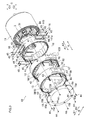
Fig. 3 ] An exploded perspective view of the motor drive portion shown inFig. 2 . - [
Fig. 4 ] An exploded perspective view of the motor drive portion shown inFig. 3 as viewed from a side opposite from a side shown inFig. 3 . - [
Fig. 5 ] A perspective view showing a first case portion of the motor drive portion shown inFig. 3 . - [
Fig. 6 ] A perspective view of the first case portion shown inFig. 5 as viewed from a side opposite to a side shown inFig. 5 . - [
Fig. 7 ] A plan view of the first case portion shown inFigs. 5 and 6 as viewed from a side along arrow A1. - [
Fig. 8 ] A perspective view for illustrating a first cooling pipe provided inside the first case portion shown inFig. 5 . - [
Fig. 9 ] A perspective view showing a second case portion of the motor drive portion shown inFig. 3 . - [
Fig. 10 ] A perspective view of the second case portion shown inFig. 9 as viewed from a side opposite to a side shown inFig. 9 . - [
Fig. 11 ] A plan view of the second case portion shown inFigs. 9 and 10 as viewed from the side along arrow A1. - [
Fig. 12 ] A plan view of the second case portion shown inFigs. 9 and 10 as viewed from a side along arrow A2. - [
Fig. 13 ] A perspective view showing the state of the second case portion shown inFig. 9 from which an inverter module is removed. - [
Fig. 14 ] A perspective view showing the state of the second case portion shown inFig. 10 from which a winding switching module and a capacitor module are removed. - [
Fig. 15 ] A perspective view showing a third case portion of the motor drive portion shown inFig. 3 . - [
Fig. 16 ] A perspective view of the third case portion shown inFig. 15 as viewed from a side opposite to a side shown inFig. 15 . - [
Fig. 17 ] A plan view of the third case portion shown inFigs. 15 and 16 as viewed from the side along arrow A1. - [
Fig. 18 ] A plan view of the third case portion shown inFigs. 15 and 16 as viewed from the side along arrow A2. - [
Fig. 19 ] A perspective view showing the state of the third case portion shown inFig. 15 from which a control board and a smoothing capacitor are removed. - [
Fig. 20 ] A perspective view showing the state of the third case portion shown inFig. 16 from which a power supply board is removed. - [
Fig. 21 ] A perspective view showing a fourth case portion of the motor drive portion shown inFig. 3 . - [
Fig. 22 ] A perspective view of the fourth case portion shown inFig. 21 as viewed from a side opposite to a side shown inFig. 21 . - [
Fig. 23 ] A plan view of the fourth case portion shown inFigs. 21 and 22 as viewed from the side along arrow A1. - [
Fig. 24 ] A perspective view for illustrating the connection relationship between internal portions of the motor drive portion shown inFig. 2 . - An embodiment of the present invention is hereinafter described on the basis of the drawings.
- The structure of a
vehicle 100 according to the embodiment of the present invention is now described with reference toFig. 1 . The structure shown inFig. 1 is a representative example showing the structure of a vehicle including a winding switching type motor drive portion, and the present invention is not restricted to this. - As shown in
Fig. 1 , thevehicle 100 includes avehicle body portion 101, amotor drive portion 10 provided inside thevehicle body portion 101, and abattery portion 20 connected to themotor drive portion 10. Themotor drive portion 10 is an example of the "motor drive device" in the present invention. - The
motor drive portion 10 is configured to include aninverter portion 1, asmoothing capacitor 2, amotor 3, awinding switching portion 4, acontrol portion 5, and apower supply portion 6. Theinverter portion 1 is an example of the "power conversion portion" in the present invention. - The
inverter portion 1 is configured to convert direct-current power input from thebattery portion 20 into three-phase (U-phase, V-phase, and W-phase) alternating-current power and output the three-phase alternating-current power to themotor 3. Theinverter portion 1 has direct-current input terminals TP1 and TN1 connected to thebattery portion 20 and alternating-current output terminals TU1, TV1, and TW1 connected to themotor 3. The direct-current input terminals TP1 and TN1 of theinverter portion 1 are connected with terminals TP2 and TN2 of thesmoothing capacitor 2, respectively. Thissmoothing capacitor 2 is provided to smooth the direct-current power input from thebattery portion 20. - The
inverter portion 1 is configured to include six switch elements Q1, Q2, Q3, Q4, Q5, and Q6 for power conversion. The switch elements Q1 and Q2 are configured to perform U-phase power conversion. The switch elements Q3 and Q4 are configured to perform V-phase power conversion. The switch elements Q5 and Q6 are configured to perform W-phase power conversion. The switch elements Q1 to Q6 each are made of a SiC semiconductor. - The
motor 3 is configured to be driven in correspondence to three-phase alternating-current power supplied from theinverter portion 1. Themotor 3 is configured to include a three-phase winding 3a for high-speed drive and a three-phase winding 3b for low-speed drive. Thewindings - The
windings inverter portion 1. Terminals TU3, TV3, and TW3 of the three phases on a second side of the winding 3a and a first side of the winding 3b are connected to a diode bridge DB1 of the windingswitching portion 4 described later. Terminals TU4, TV4, and TW4 on a second side of the winding 3b are connected to a diode bridge DB2 of the windingswitching portion 4 described later. - The winding
switching portion 4 has a function of switching the connection states of thewindings motor 3. Specifically, the windingswitching portion 4 is configured to include a high-speed winding switch SW1 to short the terminals TU3, TV3, and TW3 of themotor 3 and a low-speed winding switch SW2 to short the terminals TU4, TV4, and TW4 of themotor 3. The high-speed winding switch SW1 and the low-speed winding switch SW2 are examples of the "switch element" in the present invention. The high-speed winding switch SW1 and the low-speed winding switch SW2 each are made of a SiC semiconductor. - The winding
switching portion 4 is configured to include the diode bridge DB1 having terminals TU5, TV5, and TW5 connected to the terminals TU3, TV3, and TW3 of themotor 3 and a capacitor C1 configured to protect the winding 3a of themotor 3. The high-speed winding switch SW1, the diode bridge DB1, the capacitor C1, and the smoothingcapacitor 2 are electrically connected to each other in parallel. - The winding
switching portion 4 is configured to include the diode bridge DB2 having terminals TU6, TV6, and TW6 connected to the terminals TU4, TV4, and TW4 of themotor 3 and a capacitor C2 configured to protect the winding 3b of themotor 3. The low-speed winding switch SW2, the diode bridge DB2, the capacitor C2, and the smoothingcapacitor 2 are electrically connected to each other in parallel. - The diode bridge DB1 is constituted by six diodes D11, D12, D13, D14, D15, and D16 configured to rectify three-phase (U-phase, V-phase, and W-phase) alternating current output from the terminals TU3, TV3, and TW3 of the
motor 3. The diodes D11 and D12 are configured to rectify U-phase alternating current. The diodes D13 and D14 are configured to rectify V-phase alternating current. The diodes D15 and D16 are configured to rectify W-phase alternating current. Two diodes D17 and D18 are provided on the direct-current output side of the diode bridge DB1. - Similarly, the diode bridge DB2 is constituted by six diodes D21, D22, D23, D24, D25, and D26 configured to rectify three-phase (U-phase, V-phase, and W-phase) alternating current output from the terminals TU4, TV4, and TW4 of the
motor 3. The diodes D21 and D22 are configured to rectify U-phase alternating current. The diodes D23 and D24 are configured to rectify V-phase alternating current. The diodes D25 and D26 are configured to rectify W-phase alternating current. Two diodes D27 and D28 are provided on the direct-current output side of the diode bridge DB2. - The
control portion 5 is configured to control theinverter portion 1 and the windingswitching portion 4 by outputting control signals (an inverter control signal, a high-speed winding switching control signal, and a low-speed winding switching control signal) to theinverter portion 1 and the windingswitching portion 4. Thepower supply portion 6 is configured to supply power (gate power for the inverter) for operating the switch elements Q1 to Q6 of theinverter portion 1 and power (gate power for high-speed winding switching and gate power for low-speed winding switching) for operating the high-speed winding switch SW1 and the low-speed winding switch SW2 of the windingswitching portion 4 to theinverter portion 1 and the windingswitching portion 4, respectively. - The schematic configuration (structure) of the
motor drive portion 10 according to the embodiment of the present invention is now described with reference toFigs. 2 to 4 . - As shown in
Figs. 2 to 4 , themotor drive portion 10 includes afirst case portion 11 housing themotor 3, asecond case portion 12 housing theinverter portion 1 and the windingswitching portion 4, athird case portion 13 housing the smoothingcapacitor 2, thecontrol portion 5, and thepower supply portion 6, and afourth case portion 14 arranged between thefirst case portion 11 and thesecond case portion 12. Thefirst case portion 11, thefourth case portion 14, thesecond case portion 12, and thethird case portion 13 are made of metal such as aluminum. Thefirst case portion 11, thesecond case portion 12, thethird case portion 13, and thefourth case portion 14 are examples of the "case portion" in the present invention. - The
first case portion 11, thefourth case portion 14, thesecond case portion 12, and thethird case portion 13 are arranged in this order along the extensional direction (the axial direction (direction A) of the motor 3) of arotating shaft 31 of themotor 3 described later. As shown inFigs. 3 and4 , thefirst case portion 11, thefourth case portion 14, thesecond case portion 12, and thethird case portion 13 are formed in a cylindrical shape extending along the direction A. Thefirst case portion 11, thefourth case portion 14, thesecond case portion 12, and thethird case portion 13 formed in the cylindrical shape have outer diameters substantially equal to each other. - According to this embodiment, the
first case portion 11, thefourth case portion 14, thesecond case portion 12, and thethird case portion 13 are fastened to each other in the direction A with hexagon socket screws 41, 42, and 43 to be coupled to each other, as shown inFigs. 2 to 4 . Specifically, thefirst case portion 11 and thefourth case portion 14 are fastened to each other with the hexagon socket screws 41 to be coupled to each other, as shown inFigs. 3 and4 . Thefourth case portion 14 and thesecond case portion 12 are fastened to each other with the hexagon socket screws 42 to be coupled to each other. Thesecond case portion 12 and thethird case portion 13 are fastened to each other with the hexagon socket screws 43 to be coupled to each other. The hexagon socket screws 41 to 43 are examples of the "fastening member" in the present invention. - As shown in
Figs. 2 to 4 , a disc-shapedfirst lid 15 configured to seal thethird case portion 13 is provided on the side (side along arrow A1) of thethird case portion 13 opposite to thefirst case portion 11, thesecond case portion 12, and thefourth case portion 14. Three openable and closablesecond lids 16 in a substantially rectangular shape configured to coveropenings 141c and 141d of thefourth case portion 14 described later are provided in thefourth case portion 14. As shown inFigs. 3 and4 , thethird case portion 13 and thefirst lid 15 are fastened to each other withscrew members 44 to be coupled to each other. Thefourth case portion 14 and thesecond lids 16 are fastened to each other withscrew members 45 to be coupled to each other. - As shown in
Figs. 3 and4 , portions of thefirst case portion 11, thefourth case portion 14, thesecond case portion 12, and thethird case portion 13 coupled to each other, a portion between thethird case portion 13 and thefirst lid 15, and portions between thefourth case portion 14 and the second lids 16 (see shaded areas inFigs. 3 and4 ) are sealed with sealingmembers 50 formed by applying a liquid sealing agent having a waterproof function and drying the same. - The detailed configuration (structure) of the
first case portion 11 housing the motor 3 (seeFig. 1 ) of themotor drive portion 10 according to the embodiment of the present invention is now described with reference toFigs. 5 to 8 . - As shown in
Figs. 5 to 8 , thefirst case portion 11 has aside surface portion 111 in a cylindrical shape extending in the direction A (the axial direction of the motor 3) and abottom surface portion 112 provided on an end of theside surface portion 111 along arrow A2. As shown inFigs. 5 ,7, and 8 , screwholes 111a into which the hexagon socket screws 41 (seeFigs. 3 and4 ) configured to screw thefirst case portion 11 and thefourth case portion 14 to each other are screwed are provided in theside surface portion 111. Thescrew holes 111a are provided to extend along arrow A2 from an end face of theside surface portion 111 along arrow A1. As shown inFig. 7 , a plurality of (five in this embodiment)screw holes 111a are provided at intervals along a circumferential direction to correspond to a plurality of (five in this embodiment)screw insertion holes 141a (seeFig. 23 ) provided in aside surface portion 141 of thefourth case portion 14 described later, as viewed in the axial direction of themotor 3. A breather valve (not shown) configured to suppress damage of thefirst case portion 11 resulting from excessively increased pressure when pressure in thefirst case portion 11 is excessively increased due to an increase in temperature or the like is provided in theside surface portion 111. - As shown in
Figs. 5 to 8 , themotor 3 housed in the first case portion includes therotating shaft 31, arotor core 32, and astator core 33. The rotatingshaft 31 is provided to pass through thebottom surface portion 112 in the vicinity of a central portion of themotor 3 and extend in the direction A. Therotor core 32 is provided to surround therotating shaft 31. Thestator core 33 is arranged to be opposed to the outer periphery of therotor core 32. A plurality ofslots 34 are provided on the inner peripheral side of thestator core 33. The winding 3a for high-speed drive and the winding 3b for low-speed drive (seeFig. 1 ) are wound by lap winding or the like and are housed in the plurality ofslots 34. - As shown in
Figs. 5 and7 , themotor 3 housed in thefirst case portion 11 is connected with nineconnection wires 62 having nineconnection terminal portions 61 corresponding to the terminals TU2, TV2, TW2, TU3, TV3, TW3, TU4, TV4, and TW4 (seeFig. 1 ) of thewindings connection wires 62 are provided to protrude from an end face of thefirst case portion 11 along arrow A1 and extend in the direction A. - According to this embodiment, a
first cooling pipe 113 into which liquid coolant for cooling themotor 3 flows is provided in thefirst case portion 11, as shown inFig. 8 . A first end (an end on a side from which the liquid coolant flows in) and a second end (an end on a side of which the liquid coolant flows out) of thisfirst cooling pipe 113 are provided to protrude outward from a surface along arrow C2 in the vicinity of an end of theside surface portion 111 along arrow A1. Thefirst cooling pipe 113 is an example of the "first cooling portion" in the present invention. - The
first cooling pipe 113 is provided over the entire inner portion of theside surface portion 111 to circumferentially surround a space (a space in which themotor 3 is housed) inside theside surface portion 111. Specifically, thefirst cooling pipe 113 is formed to have a plurality of linear portions extending from the vicinity of the end along arrow A1 to the vicinity of an end along arrow A2 in the direction A inside theside surface portion 111. The plurality of linear portions extending in the direction A are alternately bent in a U shape at the end along arrow A1 and the end along arrow A2 to be connected to each other. Thus, a series of flow paths into which the liquid coolant flows is formed from the first end of thefirst cooling pipe 113 to the second end thereof. - The detailed configuration (structure) of the
second case portion 12 housing theinverter portion 1 and the winding switching portion 4 (seeFig. 1 ) of themotor drive portion 10 according to the embodiment of the present invention is now described with reference toFigs. 9 to 14 and24 . - As shown in
Figs. 9 to 14 , thesecond case portion 12 has aside surface portion 121 in a cylindrical shape extending in the direction A (the axial direction of the motor 3) and a disc-shapedfirst partition wall 122 extending along a plane orthogonal to the direction A (along a direction B and a direction C). As shown inFigs. 10 and14 , thefirst partition wall 122 is arranged on an end of theside surface portion 121 along arrow A2. - As shown in
Figs. 9 to 14 ,screw insertion holes 121a into which the hexagon socket screws 42 (seeFigs. 3 and4 ) configured to screw thesecond case portion 12 and thefourth case portion 14 to each other are inserted are provided in theside surface portion 121. Thescrew insertion holes 121a are provided to pass through theside surface portion 121 in the direction A. As shown inFig. 11 , a plurality of (seven in this embodiment)screw insertion holes 121a are provided at intervals along the circumferential direction to correspond to a plurality of (seven in this embodiment) screw holes 141b (seeFig. 23 ) provided in theside surface portion 141 of thefourth case portion 14 described later, as viewed in the axial direction of themotor 3. - As shown in
Figs. 9 ,11 , and13 , screw holes 121b into which the hexagon socket screws 43 (seeFigs. 3 and4 ) configured to screw thesecond case portion 12 and thethird case portion 13 to each other are screwed are provided in theside surface portion 121. The screw holes 121b are provided to extend along arrow A2 from an end face of theside surface portion 121 along arrow A1. As shown inFig. 11 , a plurality of (six in this embodiment) screw holes 121b are provided at intervals along the circumferential direction to correspond to a plurality of (six in this embodiment)screw insertion holes 131a (seeFigs. 17 and 18 ) provided in aside surface portion 131 of thethird case portion 13 described later, as viewed in the axial direction of themotor 3. - A breather valve (not shown) configured to suppress damage of the
second case portion 12 and electronic components placed therein resulting from excessively increased pressure when pressure in thesecond case portion 12 is excessively increased due to an increase in temperature or the like is provided in theside surface portion 121. - The
first partition wall 122 is provided to isolate the windingswitching portion 4 and theinverter portion 1 from each other in thesecond case portion 12. Specifically, theinverter portion 1 is formed by arranging aninverter module 1a mounted with the electronic component including the switch elements Q1 to Q6 (seeFig. 1 ) in a wiring substrate on a surface of thefirst partition wall 122 along arrow A1, as shown inFigs. 9 and11 . As shown inFigs. 10 and12 , the windingswitching portion 4 is formed by arranging a windingswitching module 4a mounted with the electronic component including the high-speed winding switch SW1 and the low-speed winding switch SW2 (seeFig. 1 ) in a wiring substrate and twocapacitor modules 4b on a surface of thefirst partition wall 122 along arrow A2. Thus, theinverter portion 1 is arranged in a region opposite to (along arrow A1) themotor 3 with respect to thefirst partition wall 122 of thesecond case portion 12. The windingswitching portion 4 is arranged in a region opposite to (along arrow A2) theinverter portion 1 with respect to thefirst partition wall 122 of thesecond case portion 12. According to this embodiment, an insulating heat radiation sheet may be provided in a portion between the switch elements Q1 to Q6 of theinverter module 1a and the surface of thefirst partition wall 122 along arrow A1. - As shown in
Figs. 9 and11 , three plate-likeconnection terminal portions 63 corresponding to the terminals TU1, TV1, and TW1 (seeFig. 1 ) of theinverter portion 1 are provided in theinverter module 1a. These threeconnection terminal portions 63 are provided to protrude from an end face of theinverter module 1a along arrow C1. A pair ofconnection terminal portions 64 corresponding to the terminals TP1 and TN1 (seeFig. 1 ) of theinverter portion 1 are arranged adjacent to theinverter module 1a on the surface of thefirst partition wall 122 along arrow A1. - As shown in
Figs. 9 and24 , theconnection terminal portions 64 each have a portion extending in the axial direction (direction A) and are formed in a U shape such that a first end side and a second end side thereof extend in the direction C. As shown inFig. 9 , portions (long portions extending in the direction C on a side along arrow A2) of theconnection terminal portions 64 on the first end side are arranged on the surface of thefirst partition wall 122 along arrow A1. As shown inFig. 24 , portions (short portions extending in the direction C on the side along arrow A1) of theconnection terminal portions 64 on the second end side are configured to be electrically connected to plate-likeconnection terminal portions 66, described later, of the smoothingcapacitor 2 housed in thethird case portion 13 by screws. - As shown in
Figs. 10 and12 , sixconnection terminal portions 65 corresponding to the terminals TU5, TV5, TW5, TU6, TV6, and TW6 (seeFig. 1 ) of the windingswitching portion 4 are provided in the windingswitching module 4a. Three of these sixconnection terminal portions 65 are arranged on the side along arrow B1 of a surface along arrow A2 of the windingswitching module 4a, and the remaining three are arranged on the side along arrow B2 of the surface along arrow A2 of the windingswitching module 4a. - As shown in
Fig. 10 , theconnection terminal portions 65 each are formed in an L shape having a portion extending in the direction A and a portion extending in the direction B. These portions of theconnection terminal portions 65 extending in the direction B are arranged on a surface of the windingswitching module 4a along arrow A2. As shown inFig. 24 , the portions of theconnection terminal portions 65 extending in the direction A are configured to be electrically connected to theconnection terminal portions 61 corresponding to the terminals TU3, TV3, TW3, TU4, TV4, and TW4 (seeFig. 1 ) of themotor 3 by screws. - According to this embodiment, a
second cooling pipe 123 configured to cool theinverter module 1a (inverter portion 1) and the windingswitching module 4a (winding switching portion 4) arranged on the surfaces of thefirst partition wall 122 is provided in thesecond case portion 12, as shown inFigs. 9 to 14 . A first end (an end on a side from which the liquid coolant flows in) and a second end (an end on a side of which the liquid coolant flows out) of thissecond cooling pipe 123 are provided to protrude outward from a surface along arrow B2 in the vicinity of a central portion of theside surface portion 121 in the direction C. Thesecond cooling pipe 123 is an example of the "second cooling portion" in the present invention. - As shown in
Figs. 11 to 14 , thesecond cooling pipe 123 is formed to have a U-shaped portion extending from an end along arrow B2 to the vicinity of an end along arrow B1 inside thefirst partition wall 122. Thus, a series of flow paths into which the liquid coolant flows is formed from the first end of thesecond cooling pipe 123 to the second end thereof. As shown inFig. 2 , the first end of thesecond cooling pipe 123 of the second case portion and the second end of thefirst cooling pipe 113 of thefirst case portion 11 are connected to each other through acoupling portion 70 including a tube or the like. - As shown in
Fig. 11 , thesecond cooling pipe 123 is provided to overlap with the switch elements Q1 to Q6 (seeFig. 1 ) of theinverter portion 1 mounted in theinverter module 1a, as viewed in the axial direction of themotor 3. As shown inFig. 12 , thesecond cooling pipe 123 is provided to overlap with the high-speed winding switch SW1 and the low-speed winding switch SW2 of the windingswitching portion 4 mounted in the windingswitching module 4a, as viewed in the axial direction of themotor 3. InFig. 11 , the switch elements Q1 to Q6 each are illustrated in a rectangular shape shown by a one-dot chain line. InFig. 12 , the high-speed winding switch SW1 and the low-speed winding switch SW2 each are illustrated in a rectangular shape shown by a two-dot chain line. - As shown in
Figs. 11 and 12 , threefirst holes 122a configured to allow wires connected to theinverter portion 1 of theinverter module 1a and the windingswitching portion 4 of the windingswitching module 4a to pass through are provided in thefirst partition wall 122. For example, onefirst hole 122a provided in the vicinity of an end of thefirst partition wall 122 along arrow C1 is provided to allow connection terminal portions 69 (seeFig. 24 ), described later, connected to theconnection terminal portion 63 of theinverter portion 1 to pass through when thefirst case portion 11, thefourth case portion 14, and thesecond case portion 12 are coupled to each other. Twofirst holes 122a provided in the vicinity of an end of thefirst partition wall 122 along arrow B1 are provided to allow wires (not shown) or the like configured to transmit the control signals from thecontrol portion 5 to theinverter portion 1 and the windingswitching portion 4 to pass through. - As shown in
Figs. 10 ,12 , and14 , tworecess portions 122b are provided in the surface of thefirst partition wall 122 along arrow A2. The twocapacitor modules 4b corresponding to the capacitors C1 and C2 (seeFig. 1 ) connected to the high-speed winding switch SW1 and the low-speed winding switch SW2 of the windingswitching portion 4 are arranged in these tworecess portions 122b. - The detailed configuration (structure) of the
third case portion 13 housing the smoothingcapacitor 2, thecontrol portion 5, and the power supply portion 6 (seeFig. 1 ) of themotor drive portion 10 according to the embodiment of the present invention is now described with reference toFigs. 15 to 20 and24 . - As shown in
Figs. 15 to 20 , thethird case portion 13 has theside surface portion 131 in a cylindrical shape extending in the direction A (the axial direction of the motor 3) and a disc-shapedsecond partition wall 132 extending along the plane orthogonal to the direction A (along the direction B and the direction C). As shown inFigs. 19 and 20 , thesecond partition wall 132 planarly extends in the direction B and the direction C inside theside surface portion 131. - As shown in
Figs. 15 to 20 , thescrew insertion holes 131a into which the hexagon socket screws 43 (seeFigs. 3 and4 ) configured to screw thethird case portion 13 and thesecond case portion 12 to each other are inserted are provided in theside surface portion 131. Thescrew insertion holes 131a are provided to pass through theside surface portion 131 in the direction A. As shown inFigs. 17 and 18 , a plurality of (six in this embodiment)screw insertion holes 131a are provided at intervals along the circumferential direction to correspond to the plurality of (six in this embodiment) screw holes 121b (seeFig. 11 ) provided in theside surface portion 121 of thesecond case portion 12, as viewed in the axial direction of themotor 3. - As shown in
Figs. 15 ,17 , and19 , screw holes 131b into which the screw members 44 (seeFigs. 3 and4 ) configured to screw thethird case portion 13 and thefirst lid 15 to each other are screwed are provided in theside surface portion 131. These screw holes 131b are provided to extend along arrow A2 from an end face of theside surface portion 131 along arrow A1. As shown inFig. 17 , a plurality of (eight in this embodiment) screw holes 131b are provided at intervals along the circumferential direction to correspond to a plurality of (eight in this embodiment)screw insertion holes 15a (seeFigs. 3 and4 ) provided in thefirst lid 15, as viewed in the axial direction of themotor 3. - As shown in
Figs. 15 ,17 , and19 , a through-hole 131c configured to allow aconnection wire 60 connecting acontrol board 5a described later, arranged in thethird case portion 13 and a control portion (now shown) for theentire vehicle 100 provided outside themotor drive portion 10 to each other to pass through is provided in theside surface portion 131. A portion of theside surface portion 131 of thethird case portion 13 through which theconnection wire 60 passes is sealed with a sealing agent. - A breather valve (not shown) configured to suppress damage of the
third case portion 13 and electronic components placed therein resulting from excessively increased pressure when pressure in thethird case portion 13 is excessively increased due to an increase in temperature or the like is provided in theside surface portion 131. - The
second partition wall 132 is provided to isolate the smoothingcapacitor 2 and thecontrol portion 5 from thepower supply portion 6 in thethird case portion 13. Specifically, the smoothingcapacitor 2 provided with a film capacitor or an electrolytic capacitor therein and thecontrol board 5a mounted with thecontrol portion 5 are arranged adjacent to each other in the direction B on a surface of thesecond partition wall 132 along arrow A1, as shown inFigs. 15 and17 . As shown inFigs. 16 and18 , apower supply board 6a mounted with thepower supply portion 6 is arranged on a surface of thesecond partition wall 132 along arrow A2. Thus, the smoothingcapacitor 2 and thecontrol portion 5 are arranged in a region opposite to (along arrow A1) themotor 3, the windingswitching portion 4, and theinverter portion 1 with respect to thesecond partition wall 132 of thethird case portion 13. Thepower supply portion 6 is arranged in a region opposite to (along arrow A2) the smoothingcapacitor 2 and thecontrol portion 5 with respect to thesecond partition wall 132 of thethird case portion 13. - As shown in
Figs. 15 and17 , the two plate-likeconnection terminal portions 66 corresponding to the terminals TP2 and TN2 (seeFig. 1 ) are provided in the smoothingcapacitor 2. These twoconnection terminal portions 66 are provided to protrude from a surface of the rectangularparallelepiped smoothing capacitor 2 along arrow B2. Theconnection terminal portions 66 are configured to be electrically connected to portions (short-side portions extending in the direction B on the side along arrow A2) of the pair ofconnection terminal portions 64 on the second end side corresponding to the terminals TP1 and TN1 (seeFig. 1 ) of theinverter portion 1 by screws, as shown inFig. 24 . As shown inFigs. 15 and17 ,connection wires 67 connected to the battery portion 20 (seeFig. 1 ) are screwed to theconnection terminal portions 66. These twoconnection wires 67 are provided to pass through portions of theside surface portion 131 of thethird case portion 13 on a side along arrow B2 in the vicinity of a central portion of theside surface portion 131 in the direction C and extend in the direction B. The portions of theside surface portion 131 of thethird case portion 13 through which theconnection wires 67 pass are sealed with a sealing agent. - According to this embodiment, three
second holes 132a configured to allow wires connected to thecontrol portion 5 mounted on thecontrol board 5a and thepower supply portion 6 mounted on thepower supply board 6a to pass through are provided in thesecond partition wall 132 of thethird case portion 13, as shown inFigs. 15 to 20 . For example, onesecond hole 132a provided in the vicinity of an end of thesecond partition wall 132 along arrow B2 is provided to allow the pair ofconnection terminal portions 64 corresponding to the terminals TP1 and TN1 (seeFig. 1 ) of theinverter portion 1 to pass through when thesecond case portion 12 and thethird case portion 13 are coupled to each other, as shown inFig. 24 . Twosecond holes 132a provided in the vicinity of both ends of thesecond partition wall 132 in the direction C are provided to allow wires (not shown) or the like configured to transmit the control signals from thecontrol portion 5 to pass through. - The detailed configuration (structure) of the
fourth case portion 14 of themotor drive portion 10 according to the embodiment of the present invention is now described with reference toFigs. 21 to 24 . - As shown in
Figs. 21 to 24 , thefourth case portion 14 has theside surface portion 141 in a cylindrical shape extending in the direction A (the axial direction of the motor 3) and abottom surface portion 142 provided on an end of theside surface portion 141 along arrow A2. As shown inFigs. 21 to 23 , abearing 142a connected to an end (seeFig. 5 ) along arrow A1 of therotating shaft 31 of themotor 3 housed in thefirst case portion 11 is provided in a central portion of thebottom surface portion 142. - As shown in
Figs. 21 to 23 , thescrew insertion holes 141a into which the hexagon socket screws 41 (seeFigs. 3 and4 ) configured to screw thefourth case portion 14 and thefirst case portion 11 to each other are inserted are provided in theside surface portion 141. Thescrew insertion holes 141a are provided to pass through theside surface portion 141 in the direction A. As shown inFig. 23 , the plurality of (five in this embodiment)screw insertion holes 141a are provided at intervals along the circumferential direction to correspond to the plurality of (five in this embodiment) screw holes 111a (seeFig. 7 ) provided in theside surface portion 111 of thefirst case portion 11, as viewed in the axial direction of themotor 3. - As shown in
Figs. 21 and23 , the screw holes 141b into which the hexagon socket screws 42 (seeFigs. 3 and4 ) configured to screw thefourth case portion 14 and thesecond case portion 12 to each other are screwed are provided in theside surface portion 141. These screw holes 141b are provided to extend along arrow A2 from an end face of theside surface portion 141 along arrow A1. As shown inFig. 23 , the plurality of (seven in this embodiment) screw holes 141b are provided at intervals along the circumferential direction to correspond to the plurality of (seven in this embodiment)screw insertion holes 121a (seeFig. 11 ) provided in theside surface portion 121 of thesecond case portion 12, as viewed in the axial direction of themotor 3. - A breather valve (not shown) configured to suppress damage of the
fourth case portion 14 resulting from excessively increased pressure when pressure in thefourth case portion 14 is excessively increased due to an increase in temperature or the like is provided in theside surface portion 141. - According to this embodiment, L-shaped
connection terminal portions 68 each having a portion extending in the direction A and a portion extending in the direction C are provided in thefourth case portion 14, as shown inFigs. 21 ,23 , and24 . As shown inFigs. 21 and23 , the portions of theconnection terminal portions 68 extending in the direction C are mounted on a surface along arrow A1 of thebottom surface portion 142 of thefourth case portion 14 through insulating members (not shown) made of resin. - As shown in
Fig. 24 , the portions of theconnection terminal portions 68 extending in the direction A are configured to be electrically connected to the threeconnection terminal portions 61 corresponding to the terminals TU2, TV2, TW2 (seeFig. 1 ) of themotor 3 by screws when thefirst case portion 11 and thefourth case portion 14 are coupled to each other. The portions of theconnection terminal portions 68 extending in the direction A are configured to be electrically connected to theconnection terminal portions 63 corresponding to the terminals TU1, TV1, and TW1 (seeFig. 1 ) of theinverter portion 1 of thesecond case portion 12 through theconnection terminal portions 69 by being screwed to the L-shapedconnection terminal portions 69 when thefirst case portion 11, thefourth case portion 14, and thesecond case portion 12 are coupled to each other. Thus, according to this embodiment, theconnection terminal portions motor 3 and theinverter portion 1 to each other when thefirst case portion 11, thefourth case portion 14, and thesecond case portion 12 are coupled to each other are housed in thefourth case portion 14. - According to this embodiment, the six
connection terminal portions 61 corresponding to the terminals TU3, TV3, TW3, TU4, TV4, and TW4 (seeFig. 1 ) of themotor 3 and the sixconnection terminal portions 65 corresponding to the TU5, TV5, TW5, TU6, TV6, and TW6 (seeFig. 1 ) of the windingswitching portion 4 are housed in thefourth case portion 14 in a state where the sixconnection terminal portions 61 and the sixconnection terminal portions 65 are screwed to each other when thefirst case portion 11, thefourth case portion 14, and thesecond case portion 12 are coupled to each other, as shown inFig. 24 . In other words, according to this embodiment, theconnection terminal portions motor 3 and the windingswitching portion 4 to each other are housed in thefourth case portion 14 when thefirst case portion 11, thefourth case portion 14, and thesecond case portion 12 are coupled to each other. - According to this embodiment, the
rectangular openings 141c and 141d are provided in theside surface portion 141 of thefourth case portion 14, as shown inFigs. 21 and 22 . One opening 141c is provided in a portion of theside surface portion 141 on a side along arrow C1 in the vicinity of a central portion of theside surface portion 141 in the direction B. Oneopening 141d is provided in each of portions of theside surface portion 141 on sides along arrow B1 and arrow B2 in the vicinity of a central portion of theside surface portion 141 in the direction C. The three plate-likesecond lids 16 are mounted on theside surface portion 141 of thefourth case portion 14 to cover theopenings 141c and 141d. Thesesecond lids 16 are configured to be fastened to theside surface portion 141 with thescrew members 45. - As shown in
Fig. 24 , the opening 141c is provided in a portion corresponding to theconnection terminal portions fourth case portion 14 when thefourth case portion 14 and thesecond case portion 12 are coupled to each other. Thus, theconnection terminal portions 69 connected to theconnection terminal portions 63 corresponding to the terminals TU1, TV1, and TW1 (seeFig. 1 ) of theinverter portion 1 of thesecond case portion 12 and theconnection terminal portions 68 in thefourth case portion 14 can be screwed to each other through the opening 141c outside thefourth case portion 14 when thefourth case portion 14 and thesecond case portion 12 are coupled to each other. - As shown in
Fig. 24 , theopenings 141d are provided in portions corresponding to theconnection terminal portions fourth case portion 14 when thefirst case portion 11, thefourth case portion 14, and thesecond case portion 12 are coupled to each other. Thus, the sixconnection terminal portions 61 corresponding to the terminals TU3, TV3, TW3, TU4, TV4, and TW4 (seeFig. 1 ) of themotor 3 and the sixconnection terminal portions 65 corresponding to the TU5, TV5, TW5, TU6, TV6, and TW6 (seeFig. 1 ) of the windingswitching portion 4 can be screwed to each other through theopenings 141d outside thefourth case portion 14 when thefirst case portion 11, thefourth case portion 14, and thesecond case portion 12 are coupled to each other. - According to this embodiment, three
third holes 142b configured to allow the threeconnection terminal portions 61 corresponding to the terminals TU2, TV2, and TW2 (seeFig. 1 ) of themotor 3 and the sixconnection terminal portions 61 corresponding to the terminals TU3, TV3, TW3, TU4, TV4, and TW4 (seeFig. 1 ) of themotor 3 to pass through when thefourth case portion 14 and thefirst case portion 11 are coupled to each other are provided in thebottom surface portion 142, as shown inFigs. 23 and24 . - A procedure for assembling the
motor drive portion 10 according to the embodiment of the present invention is now described with reference toFigs. 2 to 4 and24 . - As shown in
Figs. 3 and4 , first, thefirst case portion 11 housing themotor 3 inside and thefourth case portion 14 are fastened to each other in the direction A with the hexagon socket screws 41 to be coupled to each other. Specifically, first, thescrew insertion holes 141a of thefourth case portion 14 and the screw holes 111a of thefirst case portion 11 are aligned with each other. Then, the hexagon socket screws 41 are inserted into thescrew insertion holes 141a, whereby the hexagon socket screws 41 are screwed into thescrew holes 111a. At this time, the sealingmember 50 is formed on a boundary (see the shaded area inFigs. 3 and4 ) between thefirst case portion 11 and thefourth case portion 14 by applying the liquid sealing agent and drying the same. Furthermore, at this time, the end along arrow A1 of therotating shaft 31 of themotor 3 is connected to thebearing 142a of thebottom surface portion 142 of thefourth case portion 14. - At this time, the three
connection terminal portions 61 corresponding to the terminals TU2, TV2, and TW2 (seeFig. 1 ) of themotor 3 are inserted into thefourth case portion 14 through thethird holes 142b of thefourth case portion 14, as shown inFig. 24 . Then, theconnection terminal portions 61 inserted thereinto in this manner are connected to theconnection terminal portions 68 mounted through the insulating members (not shown) in thefourth case portion 14 by the screws. Furthermore, at this time, the sixconnection terminal portions 61 corresponding to the terminals TU3, TV3, TW3, TU4, TV4, and TW4 (seeFig. 1 ) of themotor 3 are also inserted into thefourth case portion 14 through the third holes 142c. - Then, the aforementioned
fourth case portion 14 coupled to thefirst case portion 11 and thesecond case portion 12 mounted with theinverter module 1a and the windingswitching module 4a are fastened to each other in the direction A with the hexagon socket screws 42 to be coupled to each other, as shown inFigs. 3 and4 . Specifically, thescrew insertion holes 121a of thesecond case portion 12 and the screw holes 141b of thefourth case portion 14 are aligned with each other. Then, the hexagon socket screws 42 are inserted into thescrew insertion holes 121a, and the hexagon socket screws 42 are screwed into the screw holes 141b. At this time, the sealingmember 50 is formed on a boundary (see the shaded area inFigs. 3 and4 ) between thesecond case portion 12 and thefourth case portion 14 by applying the liquid sealing agent and drying the same. Furthermore, at this time, theconnection terminal portions 63 corresponding to the terminals TU1, TV1, and TW1 (seeFig. 1 ) of theinverter portion 1 of theinverter module 1a and the L-shapedconnection terminal portions 69 are connected to each other by screws, as shown inFig. 24 . - Then, the aforementioned
connection terminal portions 69 connected to theconnection terminal portions 63 corresponding to the terminals TU1, TV1, and TW1 (seeFig. 1 ) of theinverter portion 1 and theconnection terminal portions 68 provided in thefourth case portion 14 are connected to each other through the opening 141c by screws, as shown inFig. 24 . Thus, the terminals TU1, TV1, and TW1 (seeFig. 1 ) of theinverter portion 1 and the terminals TU2, TV2, and TW2 (seeFig. 1 ) of themotor 3 are electrically connected to each other. Theconnection terminal portions 65 corresponding to the terminals TU5, TV5, TW5, TU6, TV6, and TW6 (seeFig. 1 ) of the windingswitching portion 4 of the windingswitching module 4a and the sixconnection terminal portions 61 corresponding to the terminals TU3, TV3, TW3, TU4, TV4, and TW4 (seeFig. 1 ) of themotor 3 are connected to each other through theopenings 141d by the screws. Then, thesecond lids 16 are mounted on thefourth case portion 14 with thescrew members 45 to cover theopenings 141c and 141d. At this time, the sealingmembers 50 are formed on the portions (see the shaded areas inFigs. 3 and4 ) between thefourth case portion 14 and thesecond lids 16 by applying the liquid sealing agent and drying the same. - Then, the aforementioned
second case portion 12 coupled to thefirst case portion 11 and thefourth case portion 14 and thethird case portion 13 mounted with the smoothingcapacitor 2, thecontrol board 5a, and thepower supply board 6a are fastened to each other in the direction A to each other with the hexagon socket screws 43 to be coupled to each other, as shown inFigs. 3 and4 . Specifically, thescrew insertion holes 131a of thethird case portion 13 and the screw holes 121b of thesecond case portion 12 are aligned with each other. Then, the hexagon socket screws 43 are inserted into thescrew insertion holes 131a, and the hexagon socket screws 43 are screwed into the screw holes 121b. At this time, the sealingmember 50 is formed on a boundary (see the shaded area inFigs. 3 and4 ) between thesecond case portion 12 and thethird case portion 13 by applying the liquid sealing agent and drying the same. Then, theconnection terminal portions 64 in thesecond case portion 12 and theconnection terminal portions 66 of the smoothingcapacitor 2 in thethird case portion 13 are connected to each other by the screws, as shown inFig. 24 . Furthermore, at this time, theinverter module 1a and the windingswitching module 4a in thesecond case portion 12 and thecontrol board 5a and thepower supply board 6a in thethird case portion 13 are connected to each other through connection wires (not shown) passing through thefirst holes 122a of thefirst partition wall 122 and thesecond holes 132a of thesecond partition wall 132. Thecontrol board 5a and the control portion (not shown) for theentire vehicle 100 provided outside themotor drive portion 10 are connected to each other through theconnection wire 60 passing through the through-hole 131c of theside surface portion 131 of thethird case portion 13. - Finally, the
first lid 15 is mounted on thethird case portion 13 to seal the side along arrow A1 of thethird case portion 13 coupled to thefirst case portion 11, thefourth case portion 14, and thesecond case portion 12, as shown inFigs. 3 and4 . Specifically, thescrew insertion holes 15a of thefirst lid 15 and the screw holes 131b of thethird case portion 13 are aligned with each other. Then, thescrew members 44 are inserted into thescrew insertion holes 15a, and thescrew members 44 are screwed into the screw holes 131b. At this time, the sealingmember 50 is formed on the portion (see the shaded area inFigs. 3 and4 ) between thethird case portion 13 and thefirst lid 15 by applying the liquid sealing agent and drying the same. - In the aforementioned manner, the motor drive portion 10 (see
Fig. 2 ) according to the embodiment of the present invention is assembled. - According to this embodiment, as hereinabove described, the
first case portion 11, thesecond case portion 12, thethird case portion 13, and thefourth case portion 14 housing theinverter portion 1, themotor 3, and the windingswitching portion 4 are provided, and thefirst case portion 11, thefourth case portion 14, thethird case portion 13, and thesecond case portion 12 are coupled to each other. Thus, thefirst case portion 11, thesecond case portion 12, thethird case portion 13, and thefourth case portion 14 housing theinverter portion 1, themotor 3, and the windingswitching portion 4 can be coupled to each other to be integrated, and hence formation of dead spaces between the case portions housing theinverter portion 1, themotor 3, and the windingswitching portion 4 can be suppressed. Consequently, thevehicle 100 in which a space for themotor drive portion 10 can be saved can be provided. This advantageous effect is effectively exerted particularly in thevehicle 100 in which it is necessary to arrange a large number of members in a limited arrangement space. - According to this embodiment, as hereinabove described, the
motor 3 is housed in the singlefirst case portion 11 different from that housing theinverter portion 1 and the windingswitching portion 4. Thus, theinverter portion 1 and the windingswitching portion 4 can be separated from themotor 3 that is a heat generator, whereby theinverter portion 1 and the windingswitching portion 4 are insusceptible to heat, and hence theinverter portion 1 and thewining switching portion 4 can operate well. Furthermore, disassembly and assembly are facilitated as compared with the case where theinverter portion 1, themotor 3, and the windingswitching portion 4 are housed in the same single case portion, and hence maintenance can be promptly carried out (or the maintenance time can be reduced). - According to this embodiment, as hereinabove described, the
motor 3 is housed in thefirst case portion 11, and theinverter portion 1 and the windingswitching portion 4 are housed in thesecond case portion 12. Thus, the simple outer shape of the device including theinverter portion 1, themotor 2, and the windingswitching portion 4 can be formed unlike the case where theinverter portion 1 and the windingswitching portion 4 are housed in the two different case portions. - According to this embodiment, as hereinabove described, the
first partition wall 122 isolating theinverter portion 1 and the windingswitching portion 4 from each other is provided in thesecond case portion 12. Furthermore, theinverter portion 1 is arranged in the region opposite to (along arrow A1) themotor 3 with respect to thefirst partition wall 122 of thesecond case portion 12, and the windingswitching portion 4 is arranged in the region opposite to (along arrow A2) theinverter portion 1 with respect to thefirst partition wall 122 of thesecond case portion 12. Thus, theinverter portion 1 and the windingswitching portion 4 can be easily arranged in thesecond case portion 12 in a state where theinverter portion 1 and the windingswitching portion 4 are separated from each other, utilizing spaces (regions) on both sides (along arrow A1 and arrow A2) of thefirst partition wall 122. - Furthermore, the
inverter portion 1 is arranged in the region opposite to (along arrow A1) themotor 3 with respect to thefirst partition wall 122 of thesecond case portion 12, and the windingswitching portion 4 is arranged in the region opposite to (along arrow A2) theinverter portion 1 with respect to thefirst partition wall 122 of thesecond case portion 12, whereby theinverter portion 1 having a smaller number of the terminals (three terminals TU1, TV1, and TW1 (seeFig. 1 )) connected to themotor 3 than the windingswitching portion 4 can be arranged at a position farther from themotor 3, and the windingswitching portion 4 having a larger number of the terminals (six terminals TU5, TV5, TW5, TU6, TV6, TW6 (seeFig. 1 )) connected to themotor 3 than theinverter portion 1 can be arranged at a position closer to themotor 3. Thus, the overall length of the wires between the terminals of themotor 3 and theinverter portion 1 and between the terminals of themotor 3 and the windingswitching portion 4 can be reduced, and hence the wiring inductance can be reduced. - According to this embodiment, as hereinabove described, the
first holes 122a allowing the wires connected to theinverter portion 1 and the winding switching portion 4 (the connection terminal portions 69 (seeFig. 24 ) connected to theconnection terminal portions 63 of theinverter portion 1 by the screws and the wires (not shown) configured to transmit the control signals from thecontrol portion 5 to theinverter portion 1 and the windingswitching portion 4, for example) to pass through are provided in thefirst partition wall 122. Thus, the wires connected to theinverter portion 1 and the windingswitching portion 4 can be housed in thesecond case portion 12 through thefirst holes 122a, and hence it is not necessary to ensure spaces for arranging the wires connected to theinverter portion 1 and the windingswitching portion 4 outside thesecond case portion 12. Consequently, the space for themotor drive portion 10 can be further saved. - According to this embodiment, as hereinabove described, the
first cooling pipe 113 configured to cool themotor 3 and thesecond cooling pipe 123 configured to cool theinverter portion 1 and the windingswitching portion 4 are provided in thefirst case portion 11 and thesecond case portion 12, respectively. Thus, themotor 3 can be easily cooled by thefirst cooling pipe 113, and theinverter portion 1 and the windingswitching portion 4 can be easily cooled by thesecond cooling pipe 123. - According to this embodiment, as hereinabove described, the
second cooling pipe 123 is provided to overlap with the switch elements Q1 to Q6 of theinverter portion 1 and the high-speed winding switch SW1 and the low-speed winding switch SW2 of the windingswitching portion 4. Thus, the switch elements Q1 to Q6, the high-speed winding switch SW1, and the low-speed winding switch SW2 that are heat generators can be effectively cooled by thesecond cooling pipe 123. - According to this embodiment, as hereinabove described, in addition to the
motor 3, theinverter portion 1, and the windingswitching portion 4, thecontrol portion 5 is housed in thefirst case portion 11, thefourth case portion 14, thesecond case portion 12, and thethird case portion 13 coupled to each other. Thus, formation of the dead spaces between the case portions housing theinverter portion 1, themotor 3, the windingswitching portion 4, and thecontrol portion 5 can be further suppressed unlike the case where a dedicated case portion for housing thecontrol portion 5 is provided separately. - According to this embodiment, as hereinabove described, in addition to the
motor 3, theinverter portion 1, the windingswitching portion 4, and thecontrol portion 5, thepower supply portion 6 is housed in thefirst case portion 11, thefourth case portion 14, thesecond case portion 12, and thethird case portion 13 coupled to each other. Thus, formation of the dead spaces between the case portions housing theinverter portion 1, themotor 3, the windingswitching portion 4, thecontrol portion 5, and thepower supply portion 6 can be further suppressed unlike the case where a dedicated case portion for housing thepower supply portion 6 is provided separately. - According to this embodiment, as hereinabove described, the
control portion 5 and thepower supply portion 6 are housed in thethird case portion 13. Thus, the device configuration can be simplified unlike the case where thecontrol portion 5 and thepower supply portion 6 are housed in two different case portions. - According to this embodiment, as hereinabove described, the
second partition wall 132 isolating thecontrol portion 5 and thepower supply portion 6 from each other is provided in thethird case portion 13. Furthermore, thecontrol portion 5 is arranged in the region opposite to (along arrow A1) themotor 3, theinverter portion 1, and the windingswitching portion 4 with respect to thesecond partition wall 132 of thethird case portion 13, and thepower supply portion 6 is arranged in the region opposite to (along arrow A2) thecontrol portion 5 with respect to thesecond partition wall 132 of thethird case portion 13. Thus, thecontrol portion 5 and thepower supply portion 6 can be easily arranged in thethird case portion 13, utilizing spaces (regions) on both sides (along arrow A1 and arrow A2) of thesecond partition wall 132. Furthermore, thecontrol portion 5 can be separated from themotor 3, theinverter portion 1, and the windingswitching portion 4 that are heat generators by thesecond partition wall 132, whereby thecontrol portion 5 is insusceptible to heat, and hence thecontrol portion 5 can operate well. - According to this embodiment, as hereinabove described, the
second holes 132a allowing the wires connected to thecontrol portion 5 and the power supply portion 6 (the pair of connection terminal portions 64 (seeFigs. 9 ,11 , and24 ) corresponding to the terminals TP1 and TN1 (seeFig. 1 ) of theinverter portion 1 and the wires (not shown) configured to transmit the control signals from thecontrol portion 5, for example) to pass through are provided in thesecond partition wall 132. Thus, the wires connected to thecontrol portion 5 and thepower supply portion 6 can be housed in thethird case portion 13 through thesecond holes 132a, and hence it is not necessary to ensure spaces for arranging the wires connected to thecontrol portion 5 and thepower supply portion 6 outside thethird case portion 13. Consequently, the space for themotor drive portion 10 can be further saved. - According to this embodiment, as hereinabove described, the smoothing
capacitor 2 is arranged in a region on the same side (along arrow A1) as thecontrol portion 5 with respect to thesecond partition wall 132 of thethird case portion 13. Thus, the smoothingcapacitor 2 can be separated from themotor 3, theinverter portion 1, and the windingswitching portion 4 that are the heat generators by thesecond partition wall 132, whereby the smoothingcapacitor 2 is insusceptible to heat. Therefore, a reduction in the performance of the smoothingcapacitor 2 resulting from heat is suppressed, so that the reliability (duration of life) of the smoothingcapacitor 2 can be further improved. - According to this embodiment, as hereinabove described, the
first case portion 11 housing themotor 3, thesecond case portion 12 housing theinverter portion 1 and the windingswitching portion 4, and thethird case portion 13 housing thecontrol portion 5 and thepower supply portion 6 are coupled to each other along the extensional direction (direction A) of therotating shaft 31 of themotor 3. Thus, thefirst case portion 11, thesecond case portion 12, and thethird case portion 13 can be formed linearly to extend along the extensional direction (direction A) of therotating shaft 31 of themotor 3 by being coupled to each other, and hence the device configuration can be simplified. Furthermore, formation of dead spaces can be further suppressed unlike the case where thefirst case portion 11, thesecond case portion 12, and thethird case portion 13 are not formed linearly by being coupled to each other. - According to this embodiment, as hereinabove described, the
first case portion 11, thesecond case portion 12, and thethird case portion 13 each are formed in the cylindrical shape extending along the extensional direction (direction A) of therotating shaft 31 of themotor 3. Thus, thefirst case portion 11, thesecond case portion 12, and thethird case portion 13 in the cylindrical shape can be easily coupled to each other along the extensional direction (direction A) of therotating shaft 31 of themotor 3. - According to this embodiment, as hereinabove described, the
first lid 15 sealing thefirst case portion 11 is provided on the side (side along arrow A1) of thethird case portion 13 opposite to thefirst case portion 11 and thesecond case portion 12. Thus, the entry of extraneous material from the side (side along arrow A1) of thethird case portion 13 opposite to thefirst case portion 11 and thesecond case portion 12 can be suppressed by thefirst lid 15. - According to this embodiment, as hereinabove described, the
fourth case portion 14 housing theconnection terminal portions motor 3 to theinverter portion 1 and the windingswitching portion 4 is provided, and thefirst case portion 11, thefourth case portion 14, thesecond case portion 12, and thethird case portion 13 are coupled to each other along the extensional direction (direction A) of therotating shaft 31 of themotor 3 in a state where thefourth case portion 14 is arranged between thefirst case portion 11 and thesecond case portion 12. Thus, theconnection terminal portions motor 3 to theinverter portion 1 and the windingswitching portion 4 can be housed in thefourth case portion 14, and hence it is not necessary to ensure spaces for arranging theconnection terminal portions fourth case portion 14. Consequently, the space for themotor drive portion 10 can be further saved. - Furthermore, the
fourth case portion 14 is arranged between thefirst case portion 11 and thesecond case portion 12, whereby theinverter portion 1 and the windingswitching portion 4 housed in thesecond case portion 12 and thecontrol portion 5 and thepower supply portion 6 housed in thethird case portion 13 can be separated from themotor 3, that is the heat generator, housed in thefirst case portion 11. Thus, theinverter portion 1, the windingswitching portion 4, thecontrol portion 5, and thepower supply portion 6 are insusceptible to heat, and hence theinverter portion 1, the windingswitching portion 4, thecontrol portion 5, and thepower supply portion 6 can operate well. - According to this embodiment, as hereinabove described, the
openings 141c and 141d are provided in the portion of theside surface portion 141 of thefourth case portion 14 corresponding to theconnection terminal portions side surface portion 141 of thefourth case portion 14 corresponding to theconnection terminal portions second lids 16 covering theopenings 141c and 141d are provided. Thus, connection and maintenance of theconnection terminal portions openings 141c and 141d. Furthermore, theopenings 141c and 141d are covered with thesecond lids 16, whereby the entry of extraneous material through theopenings 141c and 141d can be suppressed. - According to this embodiment, as hereinabove described, the portions of the
first case portion 11, thefourth case portion 14, thesecond case portion 12, and thethird case portion 13 coupled to each other, the portion between thethird case portion 13 and thefirst lid 15, and the portions between thefourth case portion 14 and the second lids 16 (see the shaded areas inFigs. 3 and4 ) are sealed with the sealingmembers 50. Thus, the entry of extraneous material from the portions of thefirst case portion 11, thefourth case portion 14, thesecond case portion 12, and thethird case portion 13 coupled to each other, the portion between thethird case portion 13 and thefirst lid 15, and the portions between thefourth case portion 14 and thesecond lids 16 can be suppressed by the sealingmembers 50. - According to this embodiment, as hereinabove described, the switch elements Q1 to Q6 of the
inverter portion 1 and the high-speed winding switch SW1 and the low-speed winding switch SW2 of the windingswitching portion 4 each are made of the SiC semiconductor. Thus, the switch elements Q1 to Q6, the high-speed winding switch SW1, and the low-speed winding switch SW2 each are made of the SiC semiconductor having excellent heat resistance, and hence the switch elements Q1 to Q6 of theinverter portion 1 and the high-speed winding switch SW1 and the low-speed winding switch SW2 of the windingswitching portion 4 can operate well with respect to heat generated by the operation of the switch elements Q1 to Q6, the high-speed winding switch SW1, and the low-speed winding switch SW2 themselves and heat transmitted through theconnection wires 62 etc. from thewindings motor 3. - According to this embodiment, as hereinabove described, the
first case portion 11, thefourth case portion 14, thesecond case portion 12, and thethird case portion 13 are fastened to each other with the hexagon socket screws 41 to 43 to be coupled to each other. Thus, thefirst case portion 11, thefourth case portion 14, thesecond case portion 12, and thethird case portion 13 can be easily coupled to each other with the hexagon socket screws 41 to 43. - The embodiment disclosed this time must be considered as illustrative in all points and not restrictive. The range of the present invention is shown not by the above description of the embodiment but by the scope of claims for patent, and all modifications within the meaning and range equivalent to the scope of claims for patent are further included.
- For example, while the example of applying the motor drive device according to the present invention to the motor drive portion mounted in the vehicle has been shown in the aforementioned embodiment, the present invention is not restricted to this. The motor drive device according to the present invention is also applicable to a common motor drive device other than the motor drive portion mounted in the vehicle.
- While the example of housing the control portion and the power supply portion in addition to the motor, the winding switching portion, and the inverter portion (power conversion portion) in the first case portion, the second case portion, the third case portion, and the fourth case portion (four (a plurality of) case portions) coupled to each other has been shown in the aforementioned embodiment, the present invention is not restricted to this. According to the present invention, at least the motor, the winding switching portion, and the power conversion portion of the motor, the winding switching portion, the power conversion portion, the control portion, and the power supply portion are simply required to be housed in the plurality of case portions coupled to each other. In this case, at least the motor, the winding switching portion, and the power conversion portion may be housed in two or three case portions coupled to each other or five or more case portions coupled to each other.
- While the example of providing the fourth case portion housing the connection terminal portions configured to electrically connect the motor to the winding switching portion and the inverter portion (power conversion portion) has been shown in the aforementioned embodiment, the present invention is not restricted to this. According to the present invention, the fourth case portion may not be provided, but only the first case portion, the second case portion, and the third case portion may be coupled to each other.
- While the example of housing the motor in the single case portion different from that housing the winding switching portion and the inverter portion (power conversion portion) has been shown in the aforementioned embodiment, the present invention is not restricted to this. According to the present invention, the motor and the winding switching portion may be housed in the same case portion, and the power conversion portion may be housed in a case portion different from that housing the motor and the winding switching portion, for example. Alternatively, the motor and the power conversion portion may be housed in the same case portion, and the winding switching portion may be housed in a case portion different from that housing the motor and the power conversion portion.
- While the example of housing the winding switching portion and the inverter portion (power conversion portion) in the second case portion has been shown in the aforementioned embodiment, the present invention is not restricted to this. According to the present invention, one of the winding switching portion and the power conversion portion may be housed in the second case portion, and the other of the winding switching portion and the power conversion portion may be housed in a case portion other than the second case portion.
- While the example of employing the first cooling pipe and the second cooling pipe into which the liquid coolant flows as the first cooling portion and the second cooling portion according to the present invention, respectively has been shown in the aforementioned embodiment, the present invention is not restricted to this. According to the present invention, cooling means (air cooling, a cooling element, or the like, for example) other than liquid cooling may be employed as the first cooling portion and the second cooling portion.
- While the example of connecting the first end of the second cooling pipe (second cooling portion) configured to cool the winding switching portion and the inverter portion (power conversion portion) and the second end of the first cooling pipe (first cooling portion) configured to cool the motor to each other has been shown in the aforementioned embodiment, the present invention is not restricted to this. According to the present invention, the first cooling portion and the second cooling portion may not be connected to each other, but the motor may be cooled independently by the first cooling portion while the winding switching portion and the power conversion portion may be cooled independently by the second cooling portion.
- While the example of coupling the first case portion, the second case portion, the third case portion, and the fourth case portion to each other along the extensional direction of the rotating shaft of the motor has been shown in the aforementioned embodiment, the present invention is not restricted to this. According to the present invention, the first case portion, the second case portion, the third case portion, and the fourth case portion may be coupled to each other along a direction orthogonal to the extensional direction of the rotating shaft of the motor, for example.
- While the example of forming each of the first case portion, the fourth case portion, the second case portion, and the third case portion in the cylindrical shape extending along the extensional direction of the rotating shaft of the motor has been shown in the aforementioned embodiment, the present invention is not restricted to this. According to the present invention, the first case portion, the fourth case portion, the second case portion, and the third case portion each may be formed in a shape (box shape, for example) other than the cylindrical shape.
- While the example of employing the sealing members formed by drying the liquid sealing agent as the sealing members sealing the portions of the first case portion, the fourth case portion, the second case portion, and the third case portion coupled to each other, the portion between the third case portion and the first case portion, and the portions between the fourth case portion and the second lids has been shown in the aforementioned embodiment, the present invention is not restricted to this. According to the present invention, an O-ring, a gasket, grease, etc. may be employed as the sealing member.
- Furthermore, according to the present invention, heat insulating members may be provided at the portions of the first case portion, the fourth case portion, the second case portion, and the third case portion coupled to each other. According to this, the first case portion, the fourth case portion, the second case portion, and the third case portion can be thermally separated from each other, and hence a cooling effect can be further increased when the first case portion, the fourth case portion, the second case portion, and the third case portion are cooled individually.
- While the example of making the switch elements of the inverter portion (power conversion portion) and the high-speed winding switch and the low-speed winding switch (switch element) of the winding switching portion of the SiC semiconductor has been shown in the aforementioned embodiment, the present invention is not restricted to this. According to the present invention, the switch elements of the power conversion portion and the winding switching portion may be made of a semiconductor (Si semiconductor, for example) other than the SiC semiconductor or a material other than a semiconductor.
- While the example of fastening the first case portion, the second case portion, the third case portion, and the fourth case portion to each other with the hexagon socket screws (fastening member) to be coupled to each other has been shown in the aforementioned embodiment, the present invention is not restricted to this. According to the present invention, the first case portion, the second case portion, the third case portion, and the fourth case portion may be fastened to each other with fastening members (swage members or the like, for example) other than the hexagon socket screws to be coupled to each other. Alternatively, according to the present invention, the first case portion, the second case portion, the third case portion, and the fourth case portion may be coupled to each other without employing fastening members. For example, the first case portion, the second case portion, the third case portion, and the fourth case portion may be welded to each other to be coupled to each other or may be bonded to each other with an adhesive agent to be coupled to each other.
Claims (24)
- A motor drive device (10) comprising:a motor (3) including a high-speed drive winding (3a) and a low-speed drive winding (3b);a winding switching portion (4) switching connection states of the high-speed drive winding and the low-speed drive winding of the motor;a power conversion portion (1) connected to the motor; anda plurality of case portions (11, 12, 13, 14) housing at least the motor, the winding switching portion, and the power conversion portion, whereinthe plurality of case portions are coupled to each other.
- The motor drive device according to claim 1, wherein
the motor is housed in a single case portion of the plurality of case portions different from those housing the winding switching portion and the power conversion portion. - The motor drive device according to claim 2, wherein
the plurality of case portions include a first case portion (11) housing the motor and a second case portion (12) housing the winding switching portion and the power conversion portion. - The motor drive device according to claim 3, wherein
the second case portion is provided with a first partition wall (122) isolating the winding switching portion and the power conversion portion from each other,
the power conversion portion is arranged in a region opposite to the motor with respect to the first partition wall of the second case portion, and
the winding switching portion is arranged in a region opposite to the power conversion portion with respect to the first partition wall of the second case portion. - The motor drive device according to claim 4, wherein
the first partition wall is provided with a first hole (122a) allowing a wire connected to the winding switching portion and the power conversion portion to pass through. - The motor drive device according to any one of claims 3 to 5, wherein
the first case portion and the second case portion are provided with a first cooling portion (113) configured to cool the motor and a second cooling portion (123) configured to cool the winding switching portion and the power conversion portion, respectively. - The motor drive device according to claim 6, wherein
the winding switching portion and the power conversion portion include a switch element (Q1, Q2, Q3, Q4, Q5, Q6, SW1, SW2), and
the second cooling portion is provided to overlap with the switch element. - The motor drive device according to any one of claims 1 to 7, further comprising a control portion (5) controlling the winding switching portion and the power conversion portion, wherein
in addition to the motor, the winding switching portion, and the power conversion portion, the control portion is housed in the plurality of case portions. - The motor drive device according to claim 8, wherein
the winding switching portion and the power conversion portion include a switch element,
the motor drive device further comprising a power supply portion (6) supplying power to operate the switch element, wherein
in addition to the motor, the winding switching portion, the power conversion portion, and the control portion, the power supply portion is housed in the plurality of case portions. - The motor drive device according to claim 9, wherein
the plurality of case portions include a third case portion (13) housing the control portion and the power supply portion. - The motor drive device according to claim 10, wherein
the third case portion is provided with a second partition wall (132) isolating the control portion and the power supply portion from each other,
the control portion is arranged in a region opposite to the motor, the winding switching portion, and the power conversion portion with respect to the second partition wall of the third case portion, and
the power supply portion is arranged in a region opposite to the control portion with respect to the second partition wall of the third case portion. - The motor drive device according to claim 11, wherein
the second partition wall is provided with a second hole (132a) allowing a wire connected to the control portion and the power supply portion to pass through. - The motor drive device according to claim 11 or 12, further comprising a smoothing capacitor (2) smoothing power input into the power conversion portion, wherein
the smoothing capacitor is arranged in a region on the same side as the control portion with respect to the second partition wall of the third case portion. - The motor drive device according to any one of claims 1 to 13, wherein
the winding switching portion and the power conversion portion include a switch element,
the motor drive device further comprising:
a control portion controlling the winding switching portion and the power conversion portion; and
a power supply portion supplying power to operate the switch element, wherein
the plurality of case portions include a first case portion housing the motor, a second case portion housing the winding switching portion and the power conversion portion, and a third case portion housing the control portion and the power supply portion, and
the first case portion, the second case portion, and the third case portion are coupled to each other along an extensional direction of a rotating shaft (31) of the motor. - The motor drive device according to claim 14, wherein
the first case portion, the second case portion, and the third case portion each are formed in a cylindrical shape extending along the extensional direction of the rotating shaft of the motor. - The motor drive device according to claim 14 or 15, wherein
a first lid (15) sealing the third case portion is provided on a side of the third case portion opposite to the first case portion and the second case portion. - The motor drive device according to any one of claims 14 to 16, wherein
the plurality of case portions further include a fourth case portion (14) housing a connection terminal portion (61, 65, 68, 69) configured to electrically connect the motor to the winding switching portion and the power conversion portion, and
the first case portion, the fourth case portion, the second case portion, and the third case portion are coupled to each other along the extensional direction of the rotating shaft of the motor in a state where the fourth case portion is arranged between the first case portion and the second case portion. - The motor drive device according to claim 17, wherein
an opening (141c, 141d) is provided at a portion of a side surface of the fourth case portion corresponding to the connection terminal portion, and
a second lid (16) being openable and closable, covering the opening is provided in the fourth case portion. - The motor drive device according to any one of claims 1 to 18, wherein
at least portions of the plurality of case portions coupled to each other are sealed with a sealing portion (50). - The motor drive device according to claim 19, wherein
the winding switching portion and the power conversion portion include a switch element,
the motor drive device further comprising:a control portion controlling the winding switching portion and the power conversion portion; anda power supply portion supplying power to operate the switch element, whereinthe plurality of case portions include a first case portion housing the motor, a second case portion housing the winding switching portion and the power conversion portion, a third case portion housing the control portion and the power supply portion, and a fourth case portion housing a connection terminal portion configured to electrically connect the motor to the winding switching portion and the power conversion portion,a first lid sealing the third case portion is provided on a side of the third case portion opposite to the first case portion and the second case portion,an opening is provided at a portion of a side surface of the fourth case portion corresponding to the connection terminal portion,a second lid being openable and closable, covering the opening is provided in the fourth case portion, andin addition to portions of the first case portion, the second case portion, the third case portion, and the fourth case portion coupled to each other, a portion between the third case portion and the first lid and a portion between the fourth case portion and the second lid are sealed with the sealing portion. - The motor drive device according to any one of claims 1 to 20, wherein
the winding switching portion and the power conversion portion include a switch element, and
the switch element is made of a SiC semiconductor. - The motor drive device according to any one of claims 1 to 21, wherein
the power conversion portion includes an inverter portion (1) converting direct-current power into alternating-current power. - The motor drive device according to any one of claims 1 to 22, wherein
the plurality of case portions are fastened to each other with a fastening member (41, 42, 43) to be coupled to each other. - A vehicle (100) comprising:
a vehicle body portion (101); and
a motor drive portion (10) provided inside the vehicle body portion, wherein
the motor drive portion includes:a motor (3) including a high-speed drive winding (3a) and a low-speed drive winding (3b),a winding switching portion (4) switching connection states of the high-speed drive winding and the low-speed drive winding of the motor,a power conversion portion (1) connected to the motor, anda plurality of case portions (11, 12, 13, 14) housing at least the motor, the winding switching portion, and the power conversion portion, andthe plurality of case portions are coupled to each other.
Applications Claiming Priority (1)
| Application Number | Priority Date | Filing Date | Title |
|---|---|---|---|
| PCT/JP2011/072477 WO2013046412A1 (en) | 2011-09-29 | 2011-09-29 | Motor drive device and vehicle |
Publications (2)
| Publication Number | Publication Date |
|---|---|
| EP2763291A1 true EP2763291A1 (en) | 2014-08-06 |
| EP2763291A4 EP2763291A4 (en) | 2015-08-26 |
Family
ID=47994519
Family Applications (1)
| Application Number | Title | Priority Date | Filing Date |
|---|---|---|---|
| EP11873390.6A Withdrawn EP2763291A4 (en) | 2011-09-29 | 2011-09-29 | DRIVING DEVICE WITH MOTOR AND VEHICLE |
Country Status (5)
| Country | Link |
|---|---|
| US (1) | US9231446B2 (en) |
| EP (1) | EP2763291A4 (en) |
| JP (1) | JP5259884B1 (en) |
| KR (1) | KR20140058677A (en) |
| WO (1) | WO2013046412A1 (en) |
Cited By (5)
| Publication number | Priority date | Publication date | Assignee | Title |
|---|---|---|---|---|
| WO2015113561A3 (en) * | 2014-02-03 | 2016-05-12 | Rolf Strothmann | Electric machine |
| EP2639946A3 (en) * | 2012-03-14 | 2017-07-12 | Kabushiki Kaisha Yaskawa Denki | Motor driving device |
| WO2018088945A1 (en) * | 2016-11-08 | 2018-05-17 | Aros Electronics Ab | Electric machine with liquid cooling |
| EP3306790A4 (en) * | 2015-05-26 | 2018-08-01 | Nissan Motor Co., Ltd. | Mechatronically integrated rotary electric machine |
| WO2021122566A1 (en) * | 2019-12-19 | 2021-06-24 | Melecs Ews Gmbh | Electronic device |
Families Citing this family (25)
| Publication number | Priority date | Publication date | Assignee | Title |
|---|---|---|---|---|
| JP5649600B2 (en) * | 2012-03-08 | 2015-01-07 | 三菱電機株式会社 | Liquid-cooled rotary electric machine |
| EP2750268B1 (en) * | 2012-12-27 | 2015-10-14 | Grundfos Holding A/S | Pump power unit |
| JP5825310B2 (en) * | 2013-09-05 | 2015-12-02 | 株式会社安川電機 | Motor drive device and vehicle |
| JP5812066B2 (en) * | 2013-09-05 | 2015-11-11 | 株式会社安川電機 | Motor drive device and vehicle |
| JP5885179B2 (en) * | 2013-12-13 | 2016-03-15 | 三菱電機株式会社 | Mechanical and electric rotating machine |
| CN105099084B (en) * | 2014-05-15 | 2017-10-17 | 中山大洋电机股份有限公司 | By the integrated dynamic system that traction electric machine and inverter are integrated |
| JP6582568B2 (en) * | 2014-07-31 | 2019-10-02 | 株式会社デンソー | DRIVE DEVICE AND ELECTRIC POWER STEERING DEVICE USING THE SAME |
| WO2016057582A1 (en) * | 2014-10-08 | 2016-04-14 | Remy Technologies, Llc | Axially extending electric machine electronics cooling tower |
| US10090727B2 (en) * | 2014-10-08 | 2018-10-02 | Borgwarner Inc. | Centrally located control electronics for electric machine |
| JP6327174B2 (en) * | 2015-02-20 | 2018-05-23 | 株式会社安川電機 | Drive device |
| US9954409B2 (en) * | 2015-07-27 | 2018-04-24 | Ford Global Technologies, Llc | Power supply device |
| US20180302019A1 (en) * | 2017-04-18 | 2018-10-18 | Ford Global Technologies, Llc | Series-parallel electric vehicle drive system |
| JP6867245B2 (en) | 2017-06-28 | 2021-04-28 | 日立Astemo株式会社 | Electric drive device and electric power steering device |
| JP6723201B2 (en) * | 2017-07-13 | 2020-07-15 | 日立オートモティブシステムズ株式会社 | Electric drive device and electric power steering device |
| FR3073341B1 (en) * | 2017-11-06 | 2021-08-06 | Whylot Sas | ELECTROMAGNETIC AXIAL FLOW MOTOR OR GENERATOR WITH COOLING CIRCUIT COMMON TO THE MOTOR AND ITS ELECTRONIC CONTROL AND POWER MEANS |
| WO2019208445A1 (en) * | 2018-04-25 | 2019-10-31 | 日本電産株式会社 | Motor unit and method for manufacturing motor unit |
| JP7067339B2 (en) * | 2018-07-25 | 2022-05-16 | 株式会社デンソー | Drive device and electric power steering device using this |
| KR102163554B1 (en) * | 2018-12-28 | 2020-10-07 | 우리산업 주식회사 | A motor driving system of a 3 phase winding-switching motor including independent electric switching block with water heatsinking circular format |
| JP2020137207A (en) * | 2019-02-15 | 2020-08-31 | 日本電産株式会社 | Motor unit |
| KR102171845B1 (en) | 2019-06-03 | 2020-10-29 | 뉴모텍(주) | Driving Motor with Inverter Housing for Electric Vehicle |
| JP6914995B2 (en) * | 2019-07-02 | 2021-08-04 | 本田技研工業株式会社 | Drive unit |
| DE102019132776A1 (en) | 2019-12-03 | 2021-06-10 | Bayerische Motoren Werke Aktiengesellschaft | Drive device for an electrically drivable motor vehicle and motor vehicle |
| JP7322840B2 (en) * | 2020-09-17 | 2023-08-08 | 株式会社デンソー | Rotating electric machine unit |
| DE102021208660A1 (en) | 2021-08-10 | 2023-02-16 | Zf Friedrichshafen Ag | Drive unit for a vehicle and vehicle |
| JP2024034954A (en) * | 2022-09-01 | 2024-03-13 | 株式会社デンソー | drive device |
Family Cites Families (21)
| Publication number | Priority date | Publication date | Assignee | Title |
|---|---|---|---|---|
| GB2181976B (en) * | 1985-10-04 | 1990-02-21 | Metal Box Plc | The coating of articles |
| EP0222563A1 (en) * | 1985-11-02 | 1987-05-20 | MB GROUP plc | The coating of articles |
| JPS63134877A (en) * | 1986-11-27 | 1988-06-07 | Pilot Ink Co Ltd | Battery-driven compressor |
| US5006744A (en) | 1988-12-27 | 1991-04-09 | General Electric Company | Integrated electronically commutated motor and control circuit assembly |
| ES2077723T5 (en) | 1990-07-06 | 2000-03-01 | Hitachi Ltd | BRUSHLESS MOTOR THAT INCORPORATES AN INTEGRATED CIRCUIT THAT HAS A PERIPHERAL MONOCHIP CIRCUIT. |
| JPH0859447A (en) | 1994-08-12 | 1996-03-05 | Kanebo Ltd | Skin protective agent |
| WO1997033359A1 (en) * | 1996-03-07 | 1997-09-12 | Seiko Epson Corporation | Motor and process for producing the same |
| JPH1028349A (en) | 1996-07-08 | 1998-01-27 | Mitsuba Corp | Waterproof structure of electric motor |
| US5859482A (en) * | 1997-02-14 | 1999-01-12 | General Electric Company | Liquid cooled electric motor frame |
| US6200108B1 (en) * | 1998-03-11 | 2001-03-13 | Aqua-Flo, Incorporated | Heat exchanging means for a pump motor using a bypass tube within a recirculating water system |
| JP2001128417A (en) * | 2000-09-18 | 2001-05-11 | Hitachi Ltd | Motor |
| JP4545354B2 (en) * | 2001-04-23 | 2010-09-15 | アスモ株式会社 | Motor and sealing structure |
| JP3948009B2 (en) | 2001-10-03 | 2007-07-25 | 株式会社安川電機 | Winding switching device for three-phase AC motor |
| JP2006197781A (en) | 2005-01-17 | 2006-07-27 | Fuji Heavy Ind Ltd | Inverter-integrated electric motor unit |
| DE102007005330A1 (en) * | 2007-01-29 | 2008-07-31 | Schunk Gmbh & Co. Kg Spann- Und Greiftechnik | Electric motor system and kit for this |
| JP4899906B2 (en) | 2007-02-07 | 2012-03-21 | トヨタ自動車株式会社 | Motor unit |
| JP4662316B2 (en) * | 2007-12-27 | 2011-03-30 | 株式会社安川電機 | AC motor winding switching device and winding switching system thereof |
| JP5325483B2 (en) * | 2008-07-07 | 2013-10-23 | 株式会社日立産機システム | Motor drive device |
| JP5327646B2 (en) * | 2009-06-24 | 2013-10-30 | 株式会社デンソー | Motor with built-in electronic circuit |
| JP5493220B2 (en) * | 2009-08-26 | 2014-05-14 | 株式会社安川電機 | Electric motor driving method and electric vehicle driving device |
| JP5370928B2 (en) * | 2010-01-14 | 2013-12-18 | 株式会社安川電機 | Motor and vehicle including the same |
-
2011
- 2011-09-29 JP JP2012541265A patent/JP5259884B1/en not_active Expired - Fee Related
- 2011-09-29 WO PCT/JP2011/072477 patent/WO2013046412A1/en not_active Ceased
- 2011-09-29 EP EP11873390.6A patent/EP2763291A4/en not_active Withdrawn
- 2011-09-29 KR KR1020147009039A patent/KR20140058677A/en not_active Ceased
-
2014
- 2014-03-25 US US14/224,072 patent/US9231446B2/en not_active Expired - Fee Related
Cited By (7)
| Publication number | Priority date | Publication date | Assignee | Title |
|---|---|---|---|---|
| EP2639946A3 (en) * | 2012-03-14 | 2017-07-12 | Kabushiki Kaisha Yaskawa Denki | Motor driving device |
| WO2015113561A3 (en) * | 2014-02-03 | 2016-05-12 | Rolf Strothmann | Electric machine |
| EP3306790A4 (en) * | 2015-05-26 | 2018-08-01 | Nissan Motor Co., Ltd. | Mechatronically integrated rotary electric machine |
| US10361608B2 (en) | 2015-05-26 | 2019-07-23 | Nissan Motor Co., Ltd. | Mechanically-electrically integrated electrical rotating apparatus with high cooling performance |
| WO2018088945A1 (en) * | 2016-11-08 | 2018-05-17 | Aros Electronics Ab | Electric machine with liquid cooling |
| US11228229B2 (en) | 2016-11-08 | 2022-01-18 | Aros Electronics Ab | Electric machine with liquid cooling |
| WO2021122566A1 (en) * | 2019-12-19 | 2021-06-24 | Melecs Ews Gmbh | Electronic device |
Also Published As
| Publication number | Publication date |
|---|---|
| CN103828199A (en) | 2014-05-28 |
| US9231446B2 (en) | 2016-01-05 |
| KR20140058677A (en) | 2014-05-14 |
| JP5259884B1 (en) | 2013-08-07 |
| EP2763291A4 (en) | 2015-08-26 |
| WO2013046412A1 (en) | 2013-04-04 |
| US20140202781A1 (en) | 2014-07-24 |
| JPWO2013046412A1 (en) | 2015-03-26 |
Similar Documents
| Publication | Publication Date | Title |
|---|---|---|
| EP2763291A1 (en) | Motor drive device and vehicle | |
| JP5565496B2 (en) | Motor drive device and vehicle | |
| CN103312095B (en) | Motor Drives and Vehicles | |
| EP2846442A2 (en) | Motor driving apparatus and vehicle | |
| CA2986550C (en) | Drive device | |
| CN104426455B (en) | Motor driving apparatus and vehicle | |
| CN103312261B (en) | Motor Drives and Vehicles | |
| CN105564220A (en) | Driving device and vehicle with the same | |
| JP2016092934A (en) | Driving device and vehicle including the same and manufacturing method of driving device | |
| US10958136B2 (en) | Drive apparatus | |
| US20140375153A1 (en) | Rotating electric machine for vehicles | |
| JP2011166981A (en) | Power conversion equipment | |
| CN103828199B (en) | Motor drive and vehicle | |
| US11695314B2 (en) | Electric drive unit for driving a vehicle | |
| JP6680083B2 (en) | Mechatronic integrated drive unit | |
| JP2021044861A (en) | Power converter | |
| US20230412038A1 (en) | Electric drive assembly system, vehicle and assembly method of electric drive assembly system | |
| JP5700144B2 (en) | Motor drive device and vehicle | |
| KR20130015360A (en) | Inverter module |
Legal Events
| Date | Code | Title | Description |
|---|---|---|---|
| PUAI | Public reference made under article 153(3) epc to a published international application that has entered the european phase |
Free format text: ORIGINAL CODE: 0009012 |
|
| 17P | Request for examination filed |
Effective date: 20140402 |
|
| AK | Designated contracting states |
Kind code of ref document: A1 Designated state(s): AL AT BE BG CH CY CZ DE DK EE ES FI FR GB GR HR HU IE IS IT LI LT LU LV MC MK MT NL NO PL PT RO RS SE SI SK SM TR |
|
| DAX | Request for extension of the european patent (deleted) | ||
| RA4 | Supplementary search report drawn up and despatched (corrected) |
Effective date: 20150727 |
|
| RIC1 | Information provided on ipc code assigned before grant |
Ipc: H02K 5/22 20060101ALI20150721BHEP Ipc: H02K 5/15 20060101ALI20150721BHEP Ipc: H02K 3/50 20060101ALI20150721BHEP Ipc: H02K 5/04 20060101AFI20150721BHEP Ipc: H02K 11/00 20060101ALI20150721BHEP Ipc: H02K 5/20 20060101ALI20150721BHEP |
|
| STAA | Information on the status of an ep patent application or granted ep patent |
Free format text: STATUS: THE APPLICATION HAS BEEN WITHDRAWN |
|
| RIC1 | Information provided on ipc code assigned before grant |
Ipc: H02K 11/00 20160101ALI20160707BHEP Ipc: H02K 5/15 20060101ALI20160707BHEP Ipc: H02K 5/20 20060101ALI20160707BHEP Ipc: H02K 11/33 20160101AFI20160707BHEP Ipc: H02K 5/04 20060101ALI20160707BHEP Ipc: H02K 5/22 20060101ALI20160707BHEP Ipc: H02K 3/50 20060101ALI20160707BHEP |
|
| 18W | Application withdrawn |
Effective date: 20160707 |