EP2763247A2 - Appareil pour fournir un rayonnement optique - Google Patents
Appareil pour fournir un rayonnement optique Download PDFInfo
- Publication number
- EP2763247A2 EP2763247A2 EP14165950.8A EP14165950A EP2763247A2 EP 2763247 A2 EP2763247 A2 EP 2763247A2 EP 14165950 A EP14165950 A EP 14165950A EP 2763247 A2 EP2763247 A2 EP 2763247A2
- Authority
- EP
- European Patent Office
- Prior art keywords
- optical
- fibre
- core
- laser
- pulse
- Prior art date
- Legal status (The legal status is an assumption and is not a legal conclusion. Google has not performed a legal analysis and makes no representation as to the accuracy of the status listed.)
- Withdrawn
Links
- 230000003287 optical effect Effects 0.000 title claims abstract description 101
- 230000005855 radiation Effects 0.000 title claims abstract description 34
- 239000013307 optical fiber Substances 0.000 claims abstract description 69
- NJPPVKZQTLUDBO-UHFFFAOYSA-N novaluron Chemical compound C1=C(Cl)C(OC(F)(F)C(OC(F)(F)F)F)=CC=C1NC(=O)NC(=O)C1=C(F)C=CC=C1F NJPPVKZQTLUDBO-UHFFFAOYSA-N 0.000 claims abstract description 54
- 238000005253 cladding Methods 0.000 claims abstract description 40
- 239000011521 glass Substances 0.000 claims abstract description 15
- 230000008878 coupling Effects 0.000 claims abstract description 5
- 238000010168 coupling process Methods 0.000 claims abstract description 5
- 238000005859 coupling reaction Methods 0.000 claims abstract description 5
- 238000000149 argon plasma sintering Methods 0.000 claims abstract description 4
- 239000002019 doping agent Substances 0.000 claims description 53
- VYPSYNLAJGMNEJ-UHFFFAOYSA-N Silicium dioxide Chemical compound O=[Si]=O VYPSYNLAJGMNEJ-UHFFFAOYSA-N 0.000 claims description 47
- YBMRDBCBODYGJE-UHFFFAOYSA-N germanium dioxide Chemical compound O=[Ge]=O YBMRDBCBODYGJE-UHFFFAOYSA-N 0.000 claims description 42
- 229910052769 Ytterbium Inorganic materials 0.000 claims description 36
- NAWDYIZEMPQZHO-UHFFFAOYSA-N ytterbium Chemical group [Yb] NAWDYIZEMPQZHO-UHFFFAOYSA-N 0.000 claims description 36
- 229910019142 PO4 Inorganic materials 0.000 claims description 32
- NBIIXXVUZAFLBC-UHFFFAOYSA-K phosphate Chemical compound [O-]P([O-])([O-])=O NBIIXXVUZAFLBC-UHFFFAOYSA-K 0.000 claims description 32
- 239000010452 phosphate Substances 0.000 claims description 32
- PNEYBMLMFCGWSK-UHFFFAOYSA-N aluminium oxide Inorganic materials [O-2].[O-2].[O-2].[Al+3].[Al+3] PNEYBMLMFCGWSK-UHFFFAOYSA-N 0.000 claims description 29
- 239000000377 silicon dioxide Substances 0.000 claims description 23
- 229910052775 Thulium Inorganic materials 0.000 claims description 21
- 229910052761 rare earth metal Inorganic materials 0.000 claims description 18
- 150000002910 rare earth metals Chemical class 0.000 claims description 18
- FRNOGLGSGLTDKL-UHFFFAOYSA-N thulium atom Chemical compound [Tm] FRNOGLGSGLTDKL-UHFFFAOYSA-N 0.000 claims description 13
- 230000001939 inductive effect Effects 0.000 claims description 6
- 239000000835 fiber Substances 0.000 description 114
- 230000000694 effects Effects 0.000 description 29
- 230000001965 increasing effect Effects 0.000 description 27
- 238000012545 processing Methods 0.000 description 23
- 238000013461 design Methods 0.000 description 21
- 239000000463 material Substances 0.000 description 21
- 238000000034 method Methods 0.000 description 19
- 238000005259 measurement Methods 0.000 description 17
- 238000004519 manufacturing process Methods 0.000 description 16
- 239000004065 semiconductor Substances 0.000 description 16
- 238000001228 spectrum Methods 0.000 description 11
- 230000008901 benefit Effects 0.000 description 10
- 238000010899 nucleation Methods 0.000 description 10
- 238000002310 reflectometry Methods 0.000 description 10
- 238000010521 absorption reaction Methods 0.000 description 9
- 230000003321 amplification Effects 0.000 description 9
- 238000003199 nucleic acid amplification method Methods 0.000 description 9
- 230000010287 polarization Effects 0.000 description 9
- 230000008569 process Effects 0.000 description 8
- ZOXJGFHDIHLPTG-UHFFFAOYSA-N Boron Chemical compound [B] ZOXJGFHDIHLPTG-UHFFFAOYSA-N 0.000 description 7
- 229910052796 boron Inorganic materials 0.000 description 7
- 230000032683 aging Effects 0.000 description 6
- 230000003595 spectral effect Effects 0.000 description 6
- 229910052691 Erbium Inorganic materials 0.000 description 5
- 229910052779 Neodymium Inorganic materials 0.000 description 5
- 230000005540 biological transmission Effects 0.000 description 5
- UYAHIZSMUZPPFV-UHFFFAOYSA-N erbium Chemical compound [Er] UYAHIZSMUZPPFV-UHFFFAOYSA-N 0.000 description 5
- 230000006872 improvement Effects 0.000 description 5
- 239000012535 impurity Substances 0.000 description 5
- 230000009021 linear effect Effects 0.000 description 5
- 238000003913 materials processing Methods 0.000 description 5
- 230000007246 mechanism Effects 0.000 description 5
- QEFYFXOXNSNQGX-UHFFFAOYSA-N neodymium atom Chemical compound [Nd] QEFYFXOXNSNQGX-UHFFFAOYSA-N 0.000 description 5
- 229910052782 aluminium Inorganic materials 0.000 description 4
- XAGFODPZIPBFFR-UHFFFAOYSA-N aluminium Chemical compound [Al] XAGFODPZIPBFFR-UHFFFAOYSA-N 0.000 description 4
- 230000015572 biosynthetic process Effects 0.000 description 4
- 238000000576 coating method Methods 0.000 description 4
- 238000001704 evaporation Methods 0.000 description 4
- 230000008020 evaporation Effects 0.000 description 4
- 238000000605 extraction Methods 0.000 description 4
- 150000002500 ions Chemical class 0.000 description 4
- 230000009022 nonlinear effect Effects 0.000 description 4
- 238000005086 pumping Methods 0.000 description 4
- 230000035882 stress Effects 0.000 description 4
- 238000012360 testing method Methods 0.000 description 4
- 241001270131 Agaricus moelleri Species 0.000 description 3
- 229910052689 Holmium Inorganic materials 0.000 description 3
- 229910052777 Praseodymium Inorganic materials 0.000 description 3
- 238000001069 Raman spectroscopy Methods 0.000 description 3
- 230000002411 adverse Effects 0.000 description 3
- 238000013459 approach Methods 0.000 description 3
- 230000015556 catabolic process Effects 0.000 description 3
- 230000008859 change Effects 0.000 description 3
- 239000011248 coating agent Substances 0.000 description 3
- 238000005520 cutting process Methods 0.000 description 3
- 238000006731 degradation reaction Methods 0.000 description 3
- 230000001419 dependent effect Effects 0.000 description 3
- 238000009826 distribution Methods 0.000 description 3
- 238000005553 drilling Methods 0.000 description 3
- 238000002474 experimental method Methods 0.000 description 3
- 230000004927 fusion Effects 0.000 description 3
- KJZYNXUDTRRSPN-UHFFFAOYSA-N holmium atom Chemical compound [Ho] KJZYNXUDTRRSPN-UHFFFAOYSA-N 0.000 description 3
- 238000010348 incorporation Methods 0.000 description 3
- 229910052698 phosphorus Inorganic materials 0.000 description 3
- 239000011574 phosphorus Substances 0.000 description 3
- 239000004033 plastic Substances 0.000 description 3
- 229920003023 plastic Polymers 0.000 description 3
- 229920000642 polymer Polymers 0.000 description 3
- PUDIUYLPXJFUGB-UHFFFAOYSA-N praseodymium atom Chemical compound [Pr] PUDIUYLPXJFUGB-UHFFFAOYSA-N 0.000 description 3
- YZCKVEUIGOORGS-OUBTZVSYSA-N Deuterium Chemical compound [2H] YZCKVEUIGOORGS-OUBTZVSYSA-N 0.000 description 2
- OAICVXFJPJFONN-UHFFFAOYSA-N Phosphorus Chemical compound [P] OAICVXFJPJFONN-UHFFFAOYSA-N 0.000 description 2
- 230000004913 activation Effects 0.000 description 2
- 230000009286 beneficial effect Effects 0.000 description 2
- 239000000919 ceramic Substances 0.000 description 2
- 238000012512 characterization method Methods 0.000 description 2
- 239000002131 composite material Substances 0.000 description 2
- 238000007796 conventional method Methods 0.000 description 2
- 229910052805 deuterium Inorganic materials 0.000 description 2
- 230000008030 elimination Effects 0.000 description 2
- 238000003379 elimination reaction Methods 0.000 description 2
- 125000002887 hydroxy group Chemical group [H]O* 0.000 description 2
- 239000012770 industrial material Substances 0.000 description 2
- 230000000670 limiting effect Effects 0.000 description 2
- 230000014759 maintenance of location Effects 0.000 description 2
- 238000005459 micromachining Methods 0.000 description 2
- 239000000203 mixture Substances 0.000 description 2
- 238000007639 printing Methods 0.000 description 2
- 235000012239 silicon dioxide Nutrition 0.000 description 2
- 239000007787 solid Substances 0.000 description 2
- 230000001629 suppression Effects 0.000 description 2
- DLYUQMMRRRQYAE-UHFFFAOYSA-N tetraphosphorus decaoxide Chemical compound O1P(O2)(=O)OP3(=O)OP1(=O)OP2(=O)O3 DLYUQMMRRRQYAE-UHFFFAOYSA-N 0.000 description 2
- 230000001052 transient effect Effects 0.000 description 2
- 238000003466 welding Methods 0.000 description 2
- 229910052692 Dysprosium Inorganic materials 0.000 description 1
- YCKRFDGAMUMZLT-UHFFFAOYSA-N Fluorine atom Chemical compound [F] YCKRFDGAMUMZLT-UHFFFAOYSA-N 0.000 description 1
- 101100456571 Mus musculus Med12 gene Proteins 0.000 description 1
- BPQQTUXANYXVAA-UHFFFAOYSA-N Orthosilicate Chemical compound [O-][Si]([O-])([O-])[O-] BPQQTUXANYXVAA-UHFFFAOYSA-N 0.000 description 1
- 229910052772 Samarium Inorganic materials 0.000 description 1
- 239000004411 aluminium Substances 0.000 description 1
- 238000000137 annealing Methods 0.000 description 1
- 230000002238 attenuated effect Effects 0.000 description 1
- 230000031018 biological processes and functions Effects 0.000 description 1
- 238000005219 brazing Methods 0.000 description 1
- 238000005229 chemical vapour deposition Methods 0.000 description 1
- 238000004891 communication Methods 0.000 description 1
- 238000010276 construction Methods 0.000 description 1
- 238000011109 contamination Methods 0.000 description 1
- 229910052593 corundum Inorganic materials 0.000 description 1
- 238000006880 cross-coupling reaction Methods 0.000 description 1
- 239000013078 crystal Substances 0.000 description 1
- 230000000994 depressogenic effect Effects 0.000 description 1
- 230000001687 destabilization Effects 0.000 description 1
- 230000001627 detrimental effect Effects 0.000 description 1
- KBQHZAAAGSGFKK-UHFFFAOYSA-N dysprosium atom Chemical compound [Dy] KBQHZAAAGSGFKK-UHFFFAOYSA-N 0.000 description 1
- 238000005516 engineering process Methods 0.000 description 1
- 239000000284 extract Substances 0.000 description 1
- 229910052731 fluorine Inorganic materials 0.000 description 1
- 239000011737 fluorine Substances 0.000 description 1
- 238000012994 industrial processing Methods 0.000 description 1
- 238000002430 laser surgery Methods 0.000 description 1
- GQYHUHYESMUTHG-UHFFFAOYSA-N lithium niobate Chemical compound [Li+].[O-][Nb](=O)=O GQYHUHYESMUTHG-UHFFFAOYSA-N 0.000 description 1
- 230000007774 longterm Effects 0.000 description 1
- 238000000691 measurement method Methods 0.000 description 1
- 229910052751 metal Inorganic materials 0.000 description 1
- 239000002184 metal Substances 0.000 description 1
- 150000002739 metals Chemical class 0.000 description 1
- 238000012986 modification Methods 0.000 description 1
- 230000004048 modification Effects 0.000 description 1
- 238000012544 monitoring process Methods 0.000 description 1
- 238000001208 nuclear magnetic resonance pulse sequence Methods 0.000 description 1
- 238000004806 packaging method and process Methods 0.000 description 1
- 238000005192 partition Methods 0.000 description 1
- 239000000843 powder Substances 0.000 description 1
- 230000001902 propagating effect Effects 0.000 description 1
- 230000009467 reduction Effects 0.000 description 1
- KZUNJOHGWZRPMI-UHFFFAOYSA-N samarium atom Chemical compound [Sm] KZUNJOHGWZRPMI-UHFFFAOYSA-N 0.000 description 1
- 229920006395 saturated elastomer Polymers 0.000 description 1
- 238000009738 saturating Methods 0.000 description 1
- 238000004611 spectroscopical analysis Methods 0.000 description 1
- 230000002269 spontaneous effect Effects 0.000 description 1
- 238000001356 surgical procedure Methods 0.000 description 1
- -1 thulium Chemical class 0.000 description 1
- WFKWXMTUELFFGS-UHFFFAOYSA-N tungsten Chemical compound [W] WFKWXMTUELFFGS-UHFFFAOYSA-N 0.000 description 1
- 229910052721 tungsten Inorganic materials 0.000 description 1
- 239000010937 tungsten Substances 0.000 description 1
- 229910001845 yogo sapphire Inorganic materials 0.000 description 1
Images


Classifications
-
- H—ELECTRICITY
- H01—ELECTRIC ELEMENTS
- H01S—DEVICES USING THE PROCESS OF LIGHT AMPLIFICATION BY STIMULATED EMISSION OF RADIATION [LASER] TO AMPLIFY OR GENERATE LIGHT; DEVICES USING STIMULATED EMISSION OF ELECTROMAGNETIC RADIATION IN WAVE RANGES OTHER THAN OPTICAL
- H01S3/00—Lasers, i.e. devices using stimulated emission of electromagnetic radiation in the infrared, visible or ultraviolet wave range
- H01S3/05—Construction or shape of optical resonators; Accommodation of active medium therein; Shape of active medium
- H01S3/06—Construction or shape of active medium
- H01S3/063—Waveguide lasers, i.e. whereby the dimensions of the waveguide are of the order of the light wavelength
- H01S3/067—Fibre lasers
- H01S3/06754—Fibre amplifiers
-
- G—PHYSICS
- G02—OPTICS
- G02B—OPTICAL ELEMENTS, SYSTEMS OR APPARATUS
- G02B6/00—Light guides; Structural details of arrangements comprising light guides and other optical elements, e.g. couplings
- G02B6/02—Optical fibres with cladding with or without a coating
- G02B6/024—Optical fibres with cladding with or without a coating with polarisation maintaining properties
-
- H—ELECTRICITY
- H01—ELECTRIC ELEMENTS
- H01S—DEVICES USING THE PROCESS OF LIGHT AMPLIFICATION BY STIMULATED EMISSION OF RADIATION [LASER] TO AMPLIFY OR GENERATE LIGHT; DEVICES USING STIMULATED EMISSION OF ELECTROMAGNETIC RADIATION IN WAVE RANGES OTHER THAN OPTICAL
- H01S3/00—Lasers, i.e. devices using stimulated emission of electromagnetic radiation in the infrared, visible or ultraviolet wave range
- H01S3/05—Construction or shape of optical resonators; Accommodation of active medium therein; Shape of active medium
- H01S3/06—Construction or shape of active medium
- H01S3/063—Waveguide lasers, i.e. whereby the dimensions of the waveguide are of the order of the light wavelength
- H01S3/067—Fibre lasers
- H01S3/06708—Constructional details of the fibre, e.g. compositions, cross-section, shape or tapering
- H01S3/06729—Peculiar transverse fibre profile
- H01S3/06733—Fibre having more than one cladding
-
- H—ELECTRICITY
- H01—ELECTRIC ELEMENTS
- H01S—DEVICES USING THE PROCESS OF LIGHT AMPLIFICATION BY STIMULATED EMISSION OF RADIATION [LASER] TO AMPLIFY OR GENERATE LIGHT; DEVICES USING STIMULATED EMISSION OF ELECTROMAGNETIC RADIATION IN WAVE RANGES OTHER THAN OPTICAL
- H01S5/00—Semiconductor lasers
- H01S5/06—Arrangements for controlling the laser output parameters, e.g. by operating on the active medium
- H01S5/065—Mode locking; Mode suppression; Mode selection ; Self pulsating
-
- H—ELECTRICITY
- H01—ELECTRIC ELEMENTS
- H01S—DEVICES USING THE PROCESS OF LIGHT AMPLIFICATION BY STIMULATED EMISSION OF RADIATION [LASER] TO AMPLIFY OR GENERATE LIGHT; DEVICES USING STIMULATED EMISSION OF ELECTROMAGNETIC RADIATION IN WAVE RANGES OTHER THAN OPTICAL
- H01S2301/00—Functional characteristics
- H01S2301/03—Suppression of nonlinear conversion, e.g. specific design to suppress for example stimulated brillouin scattering [SBS], mainly in optical fibres in combination with multimode pumping
-
- H—ELECTRICITY
- H01—ELECTRIC ELEMENTS
- H01S—DEVICES USING THE PROCESS OF LIGHT AMPLIFICATION BY STIMULATED EMISSION OF RADIATION [LASER] TO AMPLIFY OR GENERATE LIGHT; DEVICES USING STIMULATED EMISSION OF ELECTROMAGNETIC RADIATION IN WAVE RANGES OTHER THAN OPTICAL
- H01S2301/00—Functional characteristics
- H01S2301/08—Generation of pulses with special temporal shape or frequency spectrum
-
- H—ELECTRICITY
- H01—ELECTRIC ELEMENTS
- H01S—DEVICES USING THE PROCESS OF LIGHT AMPLIFICATION BY STIMULATED EMISSION OF RADIATION [LASER] TO AMPLIFY OR GENERATE LIGHT; DEVICES USING STIMULATED EMISSION OF ELECTROMAGNETIC RADIATION IN WAVE RANGES OTHER THAN OPTICAL
- H01S3/00—Lasers, i.e. devices using stimulated emission of electromagnetic radiation in the infrared, visible or ultraviolet wave range
- H01S3/0014—Monitoring arrangements not otherwise provided for
-
- H—ELECTRICITY
- H01—ELECTRIC ELEMENTS
- H01S—DEVICES USING THE PROCESS OF LIGHT AMPLIFICATION BY STIMULATED EMISSION OF RADIATION [LASER] TO AMPLIFY OR GENERATE LIGHT; DEVICES USING STIMULATED EMISSION OF ELECTROMAGNETIC RADIATION IN WAVE RANGES OTHER THAN OPTICAL
- H01S3/00—Lasers, i.e. devices using stimulated emission of electromagnetic radiation in the infrared, visible or ultraviolet wave range
- H01S3/005—Optical devices external to the laser cavity, specially adapted for lasers, e.g. for homogenisation of the beam or for manipulating laser pulses, e.g. pulse shaping
- H01S3/0064—Anti-reflection devices, e.g. optical isolaters
-
- H—ELECTRICITY
- H01—ELECTRIC ELEMENTS
- H01S—DEVICES USING THE PROCESS OF LIGHT AMPLIFICATION BY STIMULATED EMISSION OF RADIATION [LASER] TO AMPLIFY OR GENERATE LIGHT; DEVICES USING STIMULATED EMISSION OF ELECTROMAGNETIC RADIATION IN WAVE RANGES OTHER THAN OPTICAL
- H01S3/00—Lasers, i.e. devices using stimulated emission of electromagnetic radiation in the infrared, visible or ultraviolet wave range
- H01S3/05—Construction or shape of optical resonators; Accommodation of active medium therein; Shape of active medium
- H01S3/06—Construction or shape of active medium
- H01S3/063—Waveguide lasers, i.e. whereby the dimensions of the waveguide are of the order of the light wavelength
- H01S3/067—Fibre lasers
- H01S3/06708—Constructional details of the fibre, e.g. compositions, cross-section, shape or tapering
- H01S3/06712—Polarising fibre; Polariser
-
- H—ELECTRICITY
- H01—ELECTRIC ELEMENTS
- H01S—DEVICES USING THE PROCESS OF LIGHT AMPLIFICATION BY STIMULATED EMISSION OF RADIATION [LASER] TO AMPLIFY OR GENERATE LIGHT; DEVICES USING STIMULATED EMISSION OF ELECTROMAGNETIC RADIATION IN WAVE RANGES OTHER THAN OPTICAL
- H01S3/00—Lasers, i.e. devices using stimulated emission of electromagnetic radiation in the infrared, visible or ultraviolet wave range
- H01S3/05—Construction or shape of optical resonators; Accommodation of active medium therein; Shape of active medium
- H01S3/06—Construction or shape of active medium
- H01S3/063—Waveguide lasers, i.e. whereby the dimensions of the waveguide are of the order of the light wavelength
- H01S3/067—Fibre lasers
- H01S3/06708—Constructional details of the fibre, e.g. compositions, cross-section, shape or tapering
- H01S3/06716—Fibre compositions or doping with active elements
-
- H—ELECTRICITY
- H01—ELECTRIC ELEMENTS
- H01S—DEVICES USING THE PROCESS OF LIGHT AMPLIFICATION BY STIMULATED EMISSION OF RADIATION [LASER] TO AMPLIFY OR GENERATE LIGHT; DEVICES USING STIMULATED EMISSION OF ELECTROMAGNETIC RADIATION IN WAVE RANGES OTHER THAN OPTICAL
- H01S3/00—Lasers, i.e. devices using stimulated emission of electromagnetic radiation in the infrared, visible or ultraviolet wave range
- H01S3/09—Processes or apparatus for excitation, e.g. pumping
- H01S3/091—Processes or apparatus for excitation, e.g. pumping using optical pumping
- H01S3/094—Processes or apparatus for excitation, e.g. pumping using optical pumping by coherent light
- H01S3/094003—Processes or apparatus for excitation, e.g. pumping using optical pumping by coherent light the pumped medium being a fibre
- H01S3/094007—Cladding pumping, i.e. pump light propagating in a clad surrounding the active core
-
- H—ELECTRICITY
- H01—ELECTRIC ELEMENTS
- H01S—DEVICES USING THE PROCESS OF LIGHT AMPLIFICATION BY STIMULATED EMISSION OF RADIATION [LASER] TO AMPLIFY OR GENERATE LIGHT; DEVICES USING STIMULATED EMISSION OF ELECTROMAGNETIC RADIATION IN WAVE RANGES OTHER THAN OPTICAL
- H01S3/00—Lasers, i.e. devices using stimulated emission of electromagnetic radiation in the infrared, visible or ultraviolet wave range
- H01S3/09—Processes or apparatus for excitation, e.g. pumping
- H01S3/091—Processes or apparatus for excitation, e.g. pumping using optical pumping
- H01S3/094—Processes or apparatus for excitation, e.g. pumping using optical pumping by coherent light
- H01S3/094076—Pulsed or modulated pumping
-
- H—ELECTRICITY
- H01—ELECTRIC ELEMENTS
- H01S—DEVICES USING THE PROCESS OF LIGHT AMPLIFICATION BY STIMULATED EMISSION OF RADIATION [LASER] TO AMPLIFY OR GENERATE LIGHT; DEVICES USING STIMULATED EMISSION OF ELECTROMAGNETIC RADIATION IN WAVE RANGES OTHER THAN OPTICAL
- H01S3/00—Lasers, i.e. devices using stimulated emission of electromagnetic radiation in the infrared, visible or ultraviolet wave range
- H01S3/09—Processes or apparatus for excitation, e.g. pumping
- H01S3/091—Processes or apparatus for excitation, e.g. pumping using optical pumping
- H01S3/094—Processes or apparatus for excitation, e.g. pumping using optical pumping by coherent light
- H01S3/0941—Processes or apparatus for excitation, e.g. pumping using optical pumping by coherent light of a laser diode
- H01S3/09415—Processes or apparatus for excitation, e.g. pumping using optical pumping by coherent light of a laser diode the pumping beam being parallel to the lasing mode of the pumped medium, e.g. end-pumping
-
- H—ELECTRICITY
- H01—ELECTRIC ELEMENTS
- H01S—DEVICES USING THE PROCESS OF LIGHT AMPLIFICATION BY STIMULATED EMISSION OF RADIATION [LASER] TO AMPLIFY OR GENERATE LIGHT; DEVICES USING STIMULATED EMISSION OF ELECTROMAGNETIC RADIATION IN WAVE RANGES OTHER THAN OPTICAL
- H01S3/00—Lasers, i.e. devices using stimulated emission of electromagnetic radiation in the infrared, visible or ultraviolet wave range
- H01S3/10—Controlling the intensity, frequency, phase, polarisation or direction of the emitted radiation, e.g. switching, gating, modulating or demodulating
- H01S3/10007—Controlling the intensity, frequency, phase, polarisation or direction of the emitted radiation, e.g. switching, gating, modulating or demodulating in optical amplifiers
- H01S3/10015—Controlling the intensity, frequency, phase, polarisation or direction of the emitted radiation, e.g. switching, gating, modulating or demodulating in optical amplifiers by monitoring or controlling, e.g. attenuating, the input signal
-
- H—ELECTRICITY
- H01—ELECTRIC ELEMENTS
- H01S—DEVICES USING THE PROCESS OF LIGHT AMPLIFICATION BY STIMULATED EMISSION OF RADIATION [LASER] TO AMPLIFY OR GENERATE LIGHT; DEVICES USING STIMULATED EMISSION OF ELECTROMAGNETIC RADIATION IN WAVE RANGES OTHER THAN OPTICAL
- H01S3/00—Lasers, i.e. devices using stimulated emission of electromagnetic radiation in the infrared, visible or ultraviolet wave range
- H01S3/10—Controlling the intensity, frequency, phase, polarisation or direction of the emitted radiation, e.g. switching, gating, modulating or demodulating
- H01S3/10038—Amplitude control
-
- H—ELECTRICITY
- H01—ELECTRIC ELEMENTS
- H01S—DEVICES USING THE PROCESS OF LIGHT AMPLIFICATION BY STIMULATED EMISSION OF RADIATION [LASER] TO AMPLIFY OR GENERATE LIGHT; DEVICES USING STIMULATED EMISSION OF ELECTROMAGNETIC RADIATION IN WAVE RANGES OTHER THAN OPTICAL
- H01S3/00—Lasers, i.e. devices using stimulated emission of electromagnetic radiation in the infrared, visible or ultraviolet wave range
- H01S3/14—Lasers, i.e. devices using stimulated emission of electromagnetic radiation in the infrared, visible or ultraviolet wave range characterised by the material used as the active medium
- H01S3/16—Solid materials
- H01S3/1601—Solid materials characterised by an active (lasing) ion
- H01S3/1603—Solid materials characterised by an active (lasing) ion rare earth
- H01S3/1618—Solid materials characterised by an active (lasing) ion rare earth ytterbium
-
- H—ELECTRICITY
- H01—ELECTRIC ELEMENTS
- H01S—DEVICES USING THE PROCESS OF LIGHT AMPLIFICATION BY STIMULATED EMISSION OF RADIATION [LASER] TO AMPLIFY OR GENERATE LIGHT; DEVICES USING STIMULATED EMISSION OF ELECTROMAGNETIC RADIATION IN WAVE RANGES OTHER THAN OPTICAL
- H01S3/00—Lasers, i.e. devices using stimulated emission of electromagnetic radiation in the infrared, visible or ultraviolet wave range
- H01S3/14—Lasers, i.e. devices using stimulated emission of electromagnetic radiation in the infrared, visible or ultraviolet wave range characterised by the material used as the active medium
- H01S3/16—Solid materials
- H01S3/1691—Solid materials characterised by additives / sensitisers / promoters as further dopants
- H01S3/1693—Solid materials characterised by additives / sensitisers / promoters as further dopants aluminium
-
- H—ELECTRICITY
- H01—ELECTRIC ELEMENTS
- H01S—DEVICES USING THE PROCESS OF LIGHT AMPLIFICATION BY STIMULATED EMISSION OF RADIATION [LASER] TO AMPLIFY OR GENERATE LIGHT; DEVICES USING STIMULATED EMISSION OF ELECTROMAGNETIC RADIATION IN WAVE RANGES OTHER THAN OPTICAL
- H01S3/00—Lasers, i.e. devices using stimulated emission of electromagnetic radiation in the infrared, visible or ultraviolet wave range
- H01S3/14—Lasers, i.e. devices using stimulated emission of electromagnetic radiation in the infrared, visible or ultraviolet wave range characterised by the material used as the active medium
- H01S3/16—Solid materials
- H01S3/17—Solid materials amorphous, e.g. glass
- H01S3/176—Solid materials amorphous, e.g. glass silica or silicate glass
-
- H—ELECTRICITY
- H01—ELECTRIC ELEMENTS
- H01S—DEVICES USING THE PROCESS OF LIGHT AMPLIFICATION BY STIMULATED EMISSION OF RADIATION [LASER] TO AMPLIFY OR GENERATE LIGHT; DEVICES USING STIMULATED EMISSION OF ELECTROMAGNETIC RADIATION IN WAVE RANGES OTHER THAN OPTICAL
- H01S5/00—Semiconductor lasers
- H01S5/06—Arrangements for controlling the laser output parameters, e.g. by operating on the active medium
- H01S5/065—Mode locking; Mode suppression; Mode selection ; Self pulsating
- H01S5/0656—Seeding, i.e. an additional light input is provided for controlling the laser modes, for example by back-reflecting light from an external optical component
Definitions
- This invention relates to apparatus for providing optical radiation.
- the apparatus may form the basis of an apparatus for material processing.
- Fibre pulsed lasers are increasingly being adopted as the laser of choice in a number of industrial applications, such as micromachining, drilling and marking.
- peak-power-driven applications such as marking, it is essential to retain high peak powers (in excess of 2.5 to 5 kW) at high repetition rates in order to achieve faster character marking and increased throughout.
- the average power should be in excess of 10W, the pulse energy lies in the 0.1-0.5mJ range or higher, the pulse duration to be variable between 10ns and 200ns, while the peak power should remain substantially constant at about the 5kW or 10kW level for rep rates in the range 10kHz to >200kHz. Additional requirements are good beam quality such as can be provided by a low-moded or single-moded fibre laser.
- a number of different pulsed fibre laser configurations have been proposed and used in a stand-alone fashion or as part of a master-oscillator power amplifier (MOPA) configuration.
- Q-switched fibre lasers in particular, are quite attractive because they can produce high peak powers and several mJ pulse energies in a relatively simple and stable configuration.
- One of the main drawbacks of stand-alone Q-switched lasers which are intended to be used in an industrial application in a versatile manner in order to increase the application space, is that all the parameters of interest, such as the pulse repetition rate (PRR), energy, peak power and pulse width, are interrelated and cannot be controlled independently.
- PRR pulse repetition rate
- the peak power reduces as the pulse repetition frequency increases.
- the pulsed seed can be either a low power Q-switched laser or a directly modulated semiconductor laser.
- the latter can be controlled directly and provides much more freedom in defining the pulse shape and PRR, as well as, it gives the possibility of changing them at will to better fulfil the application needs.
- it is based on the well-developed and extremely reliable semiconductor technology developed over the years for the telecommunications industry. Different parameters of the amplified pulse sequences are defined accurately by controlling the gain distribution along the amplification chain.
- the local inversion in a fibre amplifier increases considerably before the arrival of a pulse towards the output end of the amplifier.
- Knowledge of the inversion distribution is very important in defining the photodarkening rate in case where a fibre prone to this performance-degrading effect is used.
- the amplification process also results in significant pulse reshaping and front-end sharpening. This is extremely important in defining pulse width and peak-power and as a consequence defines the onset of various non-linearities such as stimulated Raman scattering (SRS) and stimulated Brillouin scattering (SBS). Above a certain energy level, all pulses reshape (sharpen) considerably and reduce their pulse width.
- SRS stimulated Raman scattering
- SBS stimulated Brillouin scattering
- Another important effect that limits the output power of pulsed fibre lasers is the formation of giant pulses. These can catastrophically damage the optical components in the system.
- the effect is believed to be highly dependent upon the peak power and the spectral properties of the laser and believed to arise from stimulated Brillouin scattering (SBS).
- SBS stimulated Brillouin scattering
- the non-linear threshold is reached, forward going pulses are reflected. Giant pulses are observed, and these can catastrophically damage the amplifiers (and other devices) in pulse laser systems.
- the effect is stochastic in nature, and by itself very unpredictable.
- a single variation in the instantaneous spectral properties of a seed laser such as a laser diode
- Such damage has been observed in lasers months after they have been installed in industrial processing equipment.
- Fibre lasers are often pumped by laser diodes. These laser diodes can be damaged by undesired optical radiation propagating from the laser to the diodes. The effect is particularly severe in pulsed lasers because laser diodes are damaged by peak power rather than the energy of a pulse. Pulsed lasers have much higher peak powers than continuous wave lasers. Therefore the requirement to isolate the pumps from the laser is more stringent in a pulsed laser than a continuous wave laser.
- a very important issue related to the long-term behavior of Yb3+ doped fiber lasers and amplifiers is the effect of photodarkening.
- the effect shows as a gradual increase of the fibre background loss with time, which reduces the output power and overall efficiency of the optical system. It is believed to be related to the optical activation of pre-existing fibre color centres, with absorption bands mainly in the UV spectral region. However, the tails of the absorption bands extend into the near-IR adversely affecting the optical performance.
- Photodarkening results in gradual degradation and is not known to result in catastrophic sudden fibre failures. Photodarkening rate and final level is shown to be dependent on the active fibre degree of inversion and, as a result, different amplified systems will show different degradation.
- optical fibres require the generation and transmission of optical signals having intensities at which the transparency of the optical fibre degrades with time.
- the effect is known as photo-darkening, which is a light-induced change in the absorption of glass.
- the increase in absorption is believed to be due to the formation or activation of color centers that strongly absorb light in the UV and visible part of the spectrum.
- photodarkening shows as a sharp loss increase below a wavelength of approximately 800nm.
- the tail of this strong absorption band extends well into the 1 micron to 1.5micron region and affects adversely the losses at both the pump and signal wavelengths. This has a severe limiting effect on the performance and overall efficiency of fiber lasers and amplifiers operating in this wavelength regime.
- photo-darkening shows as a gradual pseudo-exponential decrease of the laser or amplifier output power to an asymptotic value.
- the final power drop and related time scale seems to depend on the fiber laser or amplifier operating conditions, most notably the pump and average inversion levels, as well as, the operating temperature.
- the output power drop could be compensated by the provision of additional pump sources and/or the increase of driving pump current. Both measures are highly undesirable since the former results in increased unit cost while the latter results in accelerated of the pump-unit ageing and increased catastrophic failure probability.
- Optical fibre lasers and amplifiers often include rare-earth dopant which can lead to photo-darkening via multi-photon processes. The effect is seen in at least Tm 3+ , Yb 3+ , Ce 3+ , Pr 3+ , and Eu 3+ doped silica glasses.
- Photodarkening is problematic when optical fibres are used in industrial material processing. Photodarkening can degrade the transmission in fibres used to deliver laser radiation from lasers (such as frequency-doubled, -tripled rod lasers, disk lasers, and fibre lasers) to a work piece. It can also severely limit the amount of optical power that can be generated in a fibre laser or amplified by an optical amplifier.
- lasers such as frequency-doubled, -tripled rod lasers, disk lasers, and fibre lasers
- photo-darkening resistant optical fibre.
- a fibre laser and amplifier that is resistant to photo-darkening.
- photo-darkening it is meant any light-induced decrease in transmission of glass, whether temporary or permanent.
- apparatus for providing optical radiation comprises a seed laser for providing seeding radiation, at least one amplifier for amplifying the seeding radiation, and a reflector, wherein the seed laser is a Fabry Perot semiconductor laser, the seed laser is connected to the amplifier via the reflector, the reflector is arranged to reflect a proportion of the seeding radiation emitted by the seed laser back into the seed laser, and the amplifier comprises an optical fibre which comprises a core having a refractive index n1 and a pedestal having a refractive index n2, and wherein the optical fibre includes a first cladding made of glass having a refractive index n3 surrounding the pedestal, wherein n1 is greater than n2, n2 is greater than n3.
- Incorporation of the pedestal is advantageous because it reduces the cross-coupling of signal power to the first cladding. This has been found to dramatically reduce pump diode failure in cladding pumped fibre lasers and amplifiers.
- the optical fibre is capable of transmitting optical radiation at high intensities. If the core has a low numerical aperture, then the fibre may be configured to be a so-called large mode area fibre, which in combination with the high intensities, permits the output power and/or product lifetime of fibre lasers and amplifiers to be increased, A further advantage in the design of fibre lasers and amplifiers is that fewer pump diodes are required since the optical fibre maintains its transmission quality over the product lifetime.
- the reflector may be a dispersive reflector.
- the seed laser may be characterized by an effective optical transit time.
- the reflector may be characterized by a bandwidth and a round-trip reflective time-delay variation over the bandwidth.
- the round-trip reflective time-delay variation may be greater than the effective optical transit time
- the proportion of the seeding radiation emitted by the seed laser reflected back into the seed laser may be less than 20%.
- the proportion may be between 1% and 10%.
- the reflector may be located a distance less than 5m from the seed laser.
- the distance may be less than 2m.
- the distance may be between 0.5m and 1.5m.
- the reflector may be located a distance between 5mm and 50cm from the seed laser.
- a peak power emitted from the apparatus may exceed 1kW.
- the core can comprise silica, a concentration of alumina in the range 0.1 to 4 mole percent, a concentration of phosphate in the range 2 to 20 mole percent, and the pedestal can comprise silica, phosphate and germania.
- the optical fibre may be doped with at least one rare earth dopant disposed in at least one of the core and the pedestal.
- the rare earth dopant may be ytterbium having a concentration in the range 2000 to 60000ppm.
- the concentration of ytterbium may be between approximately 15000 to 50000ppm.
- the concentration of ytterbium may be between approximately 20000 to 45000ppm.
- the core can contain a concentration of phosphate of between approximately 12 to 17 mole percent.
- concentration of phosphate in the core may be approximately 15 mole percent.
- the core can contain a concentration of alumina of between approximately 0.20 to 1 mole percent.
- concentration of alumina may be between approximately 0.3 and 0.8 mole percent.
- the optical fibre may be a multimode waveguide at a signal wavelength.
- the optical fibre may be configured to propagate single mode light without significant distortion over a substantial length.
- the optical fibre may be a single mode waveguide.
- the optical fibre can comprise at least one stress producing region for inducing birefringence in the core.
- the optical fibre can comprise a waveguide having a numerical aperture less than 0.15.
- the optical fibre may be a photo-darkening resistant optical fibre comprising a waveguide having a numerical aperture less than 0.15.
- the core can comprise silica, a concentration of alumina of between approximately 0.3 and 0.8 mole percent, a concentration of phosphate of substantially 15 mole percent, and a concentration of ytterbium substantially in the range 20000 to 45000 ppm.
- the pedestal can comprise silica, phosphate and germania.
- the waveguide may be a multimode waveguide at a signal wavelength, and wherein the waveguide is configured to propagate single mode light without significant distortion over a substantial length.
- the waveguide may be a singlemode waveguide.
- the reflector may be a fibre Bragg grating.
- the fibre Bragg grating may be chirped.
- the bandwidth may be greater than 1nm.
- the round-trip reflective time-delay variation may be between approximately 50ps and 1000ps.
- the round-trip reflective time-delay variation may be between 100ps and 600ps.
- the effective optical transit time may be between 10ps and 50ps.
- the effective optics transit time may be between 25ps and 40ps.
- the apparatus can include a laser delivery fibre, and a processing head, the apparatus being in the form of a laser for processing a material.
- the apparatus can include a controller configured to control the seed laser and the amplifier such that the optical radiation has sufficient average power and peak power to process the material over a range of pulse repetition frequencies.
- the apparatus can include a controller, wherein the optical radiation is characterized by pulses having a pulse width, and the controller varies the pulse width as the pulse repetition frequency is varied.
- the invention can comprise an apparatus for providing optical radiation comprising a seed laser, at least one amplifier, and a reflector, wherein the seed laser is connected to the amplifier via the reflector; the amplifier comprises an optical fibre having a pedestal; the seed laser comprises a laser diode characterized by an effective optical transit time; the reflector is arranged to reflect a proportion of seeding radiation emitted by the seed laser back into the seed laser; the reflector is characterized by a bandwidth and a round trip reflective time delay variation over the bandwidth; and the round trip reflective time delay variation is greater than the effective optical transit time.
- the invention can comprise a method of marking which method includes the step of providing a reflector within a marking laser, providing optical radiation comprising a seed laser, at least one amplifier, and a reflector, wherein the seed laser is connected to the amplifier via the reflector, the amplifier comprises an optical fibre that is cladding pumped, the seed laser comprises a laser diode characterized by an effective optical transit time, the reflector is arranged to reflect a proportion of seeding radiation emitted by the seed laser back into the seed laser, the reflector is characterized by a bandwidth and a round trip time delay variation over the bandwidth, and the round trip time delay variation is greater than the effective optical transit time.
- the concentration of phosphate and germania in the pedestal are selected to achieve the desired numerical aperture. Incorporation of germania has the advantage of increasing the fictive temperature of the pedestal and thus assisting in the retention of both circularity and core to pedestal concentricity and hence core to first cladding concentricity during the optical fibre manufacturing process. Core concentricity is important in the production of low-loss fusion splices.
- thulium dopant there is substantially zero thulium dopant in the core.
- other trace rare-earth dopants should also be avoided.
- the importance of eliminating thulium dopant is important in the design of fibre lasers and amplifiers as fibres containing thulium dopant have been found to be especially susceptible to photo-darkening. It is important therefore to use rare-earth dopants that have low trace amounts of thulium.
- the thulium concentration should be less than approximately 10ppm, and preferably less than ppm.
- the optical fibre can comprise at least one stress producing region for inducing birefringence in the core.
- the photo-darkening resistant optical fibre can comprise a waveguide having a numerical aperture less than 0.15, wherein the waveguide comprises a core having a refractive index n1 and a pedestal having a refractive index n2, and wherein the fibre includes a first cladding having a refractive index n3 surrounding the pedestal, wherein n1 is greater than n2, n2 is greater than n3.
- the core comprises silica, a concentration of alumina of between approximately 0.3 to 0.8 mole percent, a concentration of phosphate of substantially 15 mole percent, a concentration of ytterbium substantially in the range 20000 to 45000 ppm.
- the pedestal can comprise silica, phosphate and germania.
- the core comprises substantially zero thulium dopant.
- the optical fibre may be used in an apparatus in the form of a cladding pumped amplifying optical device comprising at least one source of pump energy. This is particularly advantageous because signal light scattering or leaking from the low numerical aperture core is preferentially captured and guided by the pedestal, and therefore is not routed back into the pumps.
- the apparatus therefore removes one of the major failure mechanisms of cladding pumped lasers, namely the catastrophic failure of pump diodes caused by unwanted signal light.
- the optical fibre may be used in an apparatus in the form of an amplifier, a laser, a master-oscillator power amplifier, a Q-switched laser or an ultra-fast laser comprising at least one source of pump energy.
- the invention may be in the form of an apparatus in the form of a laser for material processing, comprising at least one source of pump energy, an optical fibre, a laser delivery fibre, and a processing head.
- the invention may be a method of marking which method includes the step of providing a reflector within a marking laser.
- the invention may be a material when processed using apparatus according to any one of the preceding claims.
- the material may be a semiconductor package (plastic or ceramic), a key pad on a mobile phone, an iPOD, a computer, a component, a package, or a commercial or industrial product.
- Another aspect of the invention is to replace the seed laser and the reflector with a surface emitting light emitting diode (SLED).
- SLED may be amplified such that its use also dramatically reduces the onset of SBS.
- the apparatus preferably comprises an optical fibre as described above.
- apparatus 380 for providing optical radiation 381 which apparatus comprises a seed laser 382 for providing seeding radiation 387, at least one amplifier 383 for amplifying the seeding radiation 387, and a reflector 384, wherein the seed laser 382 is a Fabry Perot semiconductor laser, the seed laser 382 is connected to the amplifier 383 via the reflector 384, the amplifier 383 comprises an optical fibre 1 which comprises a pedestal 4 made from glass (as shown with reference to Figure 1 ).
- the reflector 384 is arranged to reflect a proportion 388 of the seeding radiation 387 emitted by the seed laser 382 back into the seed laser 382.
- the pedestal 4 protects the apparatus 380 from being damaged by optical radiation 381 leaking from the optical fibre 1.
- the reflector 384 protects the apparatus 380 from damage.
- the reflector 384 is believed to prevent the seed laser 382 from emitting the seeding radiation 387 in a single longitudinal mode (or a few longitudinal modes), thus suppressing the onset of stimulated Brillouin scattering.
- the reflector 384 is a dispersive reflector.
- the seed laser 382 is characterized by an effective optical transit time 386
- the reflector 384 is characterized by a bandwidth 3810 and a round-trip reflective time-delay variation 389 over the bandwidth 3810, and the round-trip reflective time-delay variation 389 is greater than the effective optical transit time 386.
- the proportion 388 may be less than 20%.
- the proportion is preferably 1% to 10%.
- the reflector 384 is located a distance 3811 from the seed laser 382.
- a 1m distance corresponds to approximately 10ns round trip delay in an optical fibre.
- the build up time for stimulated Brillouin scattering in optical fibres is approximately 20ns to 40ns depending upon the material composition. It is important that the reflector 384 is positioned such that the feedback has time to influence the emission from the seed laser 382.
- the distance 3811 should be less than 5m.
- the distance 3811 should ideally be less than 2m.
- the distance is preferably between 0.5m and 1.5m.
- the reflector 384 may be packaged with the seed laser 382, and the distance 3811 may be between 5mm and 50cm.
- the invention has most utility for apparatus 380 configured as a pulsed fibre lasers which may have a peak powers greater than 1 kW within the first 200ns of switch on.
- the above distances 3811 may be selected to ensure that the feedback from the reflector 384 occurs while the apparatus 380 is emitting power above 1kW.
- effective optical transit time 386 it is meant the time taken for light to propagate in a forwards direction through the seed laser 382.
- Figure 1 shows an optical fibre 1 that contains a waveguide 2.
- the waveguide 2 comprises a core 3 having a refractive index n1 and a pedestal 4 having a refractive index n2, and a first cladding 5 made of glass and having a refractive index n3.
- the optical fibre 1 is preferably coated with a coating that has a refractive index less than n3.
- the fibre 1 can then be cladding pumped by coupling pump radiation into at least the first cladding 5.
- the coating is preferably a polymer. It has been found that cladding pumped fibre lasers are less resistant to optical radiation damaging the pump diodes when pedestal fibres such as shown in Figure 1 are used within the amplifiers.
- the optical fibre 1 is side pumped.
- the optical fibre 1 is preferably a photo-darkening resistant optical fibre.
- resistant we mean that the increase in attenuation of the optical fibre 1 during operation should be no greater than 10%.
- the increase in attenuation should be no greater than 5% in 2,000 hours.
- the increase should be less than 1% in 2,000 hours. Measurement data on photo-darkening is described in detail below.
- the optical fibre 1 preferably has a numerical aperture less than 0.15.
- silica it is meant pure silica, doped silica, and heavily doped silica glasses, which glasses are sometimes referred to as silicate or silicic glasses.
- phosphate it is meant oxides of phosphorus such as phosphorus pentoxide (P 2 O 5 ).
- alumina it is meant oxides of aluminum (referred to as “aluminium” in Europe) such as Al 2 O 3 .
- germania it is meant the oxides of germania, and in particular GeO 2 .
- ytterbium it is meant ytterbium incorporated into the glass as an oxide, and the concentration in ppm is the concentration of the ions of ytterbium, and in particular Yb 3+ .
- concentration in ppm is the concentration of the ions of rare-earth metal.
- Figure 2 shows a refractive index profile 20 of the fibre 1
- the refractive indices of the core 3, pedestal 4, and first cladding 5 are n1, n2 and n3 respectively. It is preferred that n1 is greater than n2 and n2 is greater than n3.
- the preferred embodiment has a core 3 that comprises silica glass with a concentration of alumina of between approximately 0.3 to 0.8 mole percent, and a concentration of phosphate of substantially 15 mole percent. It is preferred that there is substantially zero thulium dopant. It is preferred that the pedestal 4 comprises silica, phosphate and germania.
- the first cladding 5 may be pure silica, fluorine doped silica, or other cladding materials (including polymers) used in the manufacture of optical fibres. In the event that the first cladding 5 is a glass, the fibre 1 is preferably coated with a polymer which can have an index lower than the refractive index of the first cladding 5 in order to guide pump light in amplifiers and lasers.
- At least one of the core 3 and pedestal 4 is doped with rare-earth dopant.
- the rare earth dopant may be ytterbium whose concentration is preferably substantially in the range 20000 to 45000 ppm.
- the optical fibre 1 is capable of transmitting optical radiation under high pumping and inversion conditions as well as high intensities.
- the low numerical aperture means that the fibre 1 may be configured to be a so-called large mode area fibre, which in combination with the high pumping and inversion conditions, permits the output power and/or product lifetime of fibre lasers and amplifiers to be increased.
- the design of large mode area fibres is described in United States Patent no 6614975 .
- a further advantage in the design of fibre lasers and amplifiers is that fewer pump diodes are required since the optical fibre maintains its transmission quality over the product lifetime.
- the core 3 can comprise silica, with a concentration of alumina in the range 0.1 to 4 mole percent and a concentration of phosphate in the range 2 to 20 mole percent.
- the alumina doped core in combination with the germano-phosphorus doped pedestal permits low numerical aperture fibres to be manufacturable with improved repeatability as compared with the prior art. Numerical apertures as low as 0.06 to 0.1, or preferably approximately 0.08 are readily achievable.
- the pedestal 4 can comprise silica, phosphate and germania.
- concentration of phosphate and germania are selected to achieve the desired numerical aperture.
- Incorporation of germania has the advantage of increasing the fictive temperature of the pedestal 4 and thus assisting in the retention of both circularity and core 3 to pedestal 4 concentricity, and hence core 3 to first cladding 5 concentricity, during the optical fibre manufacturing process. Core concentricity is important in the production of low-loss fusion splices.
- thulium dopant there is substantially zero thulium dopant in the core 3.
- the importance of eliminating thulium dopant is significant in the design of fibre lasers and amplifiers as fibres containing thulium dopant have been found to be especially susceptible to photo-darkening. It is important therefore to use rare-earth dopants that have low trace amounts of thulium.
- the thulium concentration should be less than approximately 10ppm, and preferably less than 1 ppm.
- the optical fibre 1 can be doped with at least one rare earth dopant disposed in at least one of the core 3 and the pedestal 4.
- the rare earth dopant can be ytterbium having a concentration in the range 2000 to 60000ppm.
- the concentration of ytterbium can be between approximately 15000 to 50000ppm.
- the concentration of ytterbium is preferably between approximately 20000 to 45000ppm.
- the concentration of phosphate in the core 3 can be between approximately 12 to 17 mole percent.
- the concentration of phosphate in the core 3 is preferably approximately 15 mole percent.
- the concentration of alumina can be between approximately 0.20 to 1 mole percent.
- the concentration of alumina is preferably between approximately 0.3 to 0.8 mole percent.
- the optical fibre 1 can be manufactured using chemical vapour deposition and solution doping. Techniques are described in United States patent numbers 4787927 , 4815079 , 4826288 , 5047076 , and 5151117 .
- the waveguide 2 can be a multimode waveguide at a signal wavelength.
- the waveguide 2 can be configured to propagate single mode light without significant distortion and/or mode coupling over a substantial length.
- Such designs are important for the design of high power fibre lasers and amplifiers, particularly for application in spectroscopy, industrial materials processing, laser surgery, and aerospace applications. Examples of core designs, techniques to propagate single mode light, and use of bend losses to remove (at least partially) unwanted higher order modes are described in United States patent numbers 5818630 , 6496301 , 6614975 , and 6954575 .
- the waveguide 2 can be a single mode waveguide.
- Figure 3 shows an optical fibre 30 which includes stress producing region 31 for inducing birefringence in the core 3.
- the core 3 can be circular or elliptical. Alternatively, or additionally, birefringence can be induced by making at least one of the pedestal 4 and core 3 elliptical.
- Figure 14 shows an optical fibre 140 having an elliptical pedestal 4 for inducing birefringence.
- the optical fibre 140 also includes an inner cladding 141 designed to have a higher viscosity than that of the pedestal 4. This can be achieved, for example, by including boron dopant in the pedestal 4 in order to depress its refractive index. Techniques to manufacture such birefringent fibres are described in United States Patent nos. 4274854 and 4426129 .
- optical fibres 30 and 140 can also be single polarization optical fibres which may be single mode or multimode as described in United States patent no 6496301 and co-pending and commonly-owned United States patent application 10/528895 .
- Figure 4 shows an apparatus in the form of a cladding pumped amplifying optical device 40 comprising pump 44 and an optical fibre 41.
- the optical fibre 41 can be the optical fibre 1, 30 or 140.
- the cladding pumped optical device 40 utilizes a composite fibre 42 comprising the optical fibre 41 and pump fibres 43 within a common coating 46.
- the composite fibre 42 is described in United States Patent no. 6826335 .
- Other cladding pumped fibres and arrangements are also possible, such as those described in United States patent nos. 4815079 , 5854865 , 5864644 , and 6731837 .
- the invention is particularly advantageous because signal light scattering or leaking from the low numerical aperture core 3 is preferentially captured and guided by the pedestal 4, and therefore is not routed back into the pumps 44.
- the apparatus therefore removes one of the major failure mechanisms of cladding pumped lasers, namely the catastrophic failure of pump diodes caused by unwanted signal light.
- the cladding pumped optical device 40 can be an amplifier, a laser, a master-oscillator power amplifier, a Q-switched laser or an ultra-fast laser comprising at least one source of pump energy.
- ultra-fast laser it is meant a laser, including for example a laser in the form of a mode locked laser and/or a master-oscillator power amplifier, that emits pulses having pulse widths less than 1ns, and more preferably less than 10ps. Designs and applications of ultra-fast lasers are disclosed in United States Patent nos 6885683 , 6275512 , 5627848 , 5696782 .
- FIG. 5 shows an apparatus in the form of a laser 50 for material processing.
- the laser 50 comprises the amplifying optical device 40, a laser delivery fibre 51, and a processing head 52.
- the processing head 52 can be a scanner, a galvanometer, or a focusing lens.
- the laser 50 is particularly useful for marking, microwelding, printing, micromachining and cutting of metals, plastics and other materials.
- Figure 6 shows the effect of photodarkening in four continuous-wave fibre lasers that each comprise a core 3 doped with ytterbium, alumina, germania, and oxides of boron.
- the figure shows a measurement of output power 61 with time 66 for four different fiber lasers.
- the cores 3 of each of these fiber lasers were doped with a standard commercially-available source of ytterbium dopant.
- Line 62 shows a measurement from a fiber laser that is doped with standard commercially-available ytterbium dopant that has a high thulium content. A rapid decrease in output power 61 is observed.
- Line 63 shows a measurement taken at 30C from a fiber laser that outputs a continuous wave output power of 60W.
- the fiber core 1 was doped with a standard commercially available ytterbium. Again, there is a rapid decrease in output power 61 observable.
- Line 64 shows a measurement taken at 70C from a fiber laser that outputs a continuous wave output power of 110W.
- line 65 shows a measurement taken at 30C from a fiber laser that outputs a continuous wave output power of 60W.
- the ytterbium dopant is high purity, with a specified impurity level of less than 1 part in 10 6 .
- the ytterbium dopant is high purity, with a specified impurity level of less than 1 part in 10 6 (1ppm).
- Comparing lines 63 and 65 the use of high purity ytterbium has reduced the effect of photodarkening when measured at the same levels of output power and temperature. Comparing lines 64 to 65, increasing temperature from 30C to 70C has caused an increase in photodarkening. There is clearly a significant improvement in the resistance to photodarkening achieved by utilizing Yb-dopant with very low levels of thulium and other impurities. It is believed that the remaining photodarkening effect is due to the other refractive-index-controlling core co-dopants, namely alumina, germania and oxides of boron.
- Kitabayashi et al. in their paper entitled " Population inversion factor dependence of photodarkening of Yb-doped fibers and its suppression by highly aluminum doping" published in the Proceedings of Optical Fiber Communications 2006 Conference , disclose that photodarkening in Yd-doped fibers can be reduced, but not entirely eliminated, by incorporating aluminum doping. This publication is incorporated by reference herein.
- Figure 7 shows the improvement obtained by including phosphate dopant in a core 1 that had been doped with alumina.
- the core 1 contains no germania and no boron doping.
- the core 1 was doped with high purity oxides of ytterbium (total impurity content specified to be better than 1ppm) in order to keep contamination due to thulium and other rare-earths to a minimum.
- Curve 67 shows the result with alumina dopant
- curve 68 shows the result with alumina and phosphate dopant.
- alumina on its own cannot entirely suppress the photodarkening effects.
- phosphate co-dopants in addition to alumina results in a dramatic improvement and dramatically reduces photodarkening effects in ytterbium-doped fibers.
- use of alumina dopant in the core also enables low numerical aperture waveguides to be produced with higher reproducibility than with phosphate doping alone.
- Photodarkening of optical fibres can also be characterized by monitoring the increase in absorption (around the 1micron region of interest) of the optical fibre, subjected to an accelerated-ageing test.
- the ageing is accelerated by pumping the ytterbium doped core to achieve the maximum possible inversion.
- the measurements shown with reference to Figures 8 to 10 were obtained by core-pumping approximately 0.1 to 1m lengths of the fibres with approximately 400mW of pump light at 976nm, and coupling white light from a tungsten filament into the core.
- the spectral absorption was then measured by a cut-back measurement.
- the measurement method follows the method published in a paper, " Photodarkening in ytterbium-doped silica fibers" by L.L.
- Figures 11 and 12 show the output power 110 versus time 11 from fibre lasers utilizing the fibre of Figure 1 , with dopants similar to those used in the accelerated ageing test of Figure 10 .
- the upper measurement line in each figure is the output power 110, whereas the lower line is the ambient temperature 112 at which the measurements were taken.
- the fibre laser used to obtain the results shown in Figure 11 was a master oscillator power amplifier MOPA (not shown), emitting 12W average power with 20 kHz pulses having pulse energies of 0.6 mJ and pulse widths of 35ns.
- the fibre laser used to obtain the results shown in Figure 12 was a continuous wave laser which was modulated at 10kHz by turning the laser diodes used as pump sources off and on repeatedly at 10kHz and with a 70% duty factor. No degradation of the output power 110 with time 111 is observable in either Figure 11 or Figure 12 over two to three months of continuous operation for both the high-peak power pulsed MOPA, and the continuous wave laser.
- Figure 13 shows the refractive index profile 130 for a preferred embodiment of the invention.
- the profile 130 differs from the idealized profile of Figure 2 in that it contains a central depression 130 in the core 3 owing to evaporation of dopants (particularly phosphate) in the collapse.
- the refractive index difference 131 between core 3 and pedestal 4 is given by n 1 - n 2 , which is approximately 0.0032. This corresponds to a numerical aperture of approximately 0.096.
- the refractive index difference 132 between pedestal 4 and first cladding 5 is approximately 0.0097, which corresponds to a numerical aperture of approximately 0.17.
- the core 3 was doped with alumina with a dopant concentration of approximately 0.70 mole percent, phosphate with a dopant concentration of approximately 15 mole percent, and ytterbium with a dopant concentration of approximately 25000ppm.
- the ytterbium dopant was provided by the oxide of ytterbium with an impurity content less than 1ppm, and thus substantially no thulium dopant was included in the core 3.
- the pedestal 4 was doped with phosphorus and germania at levels sufficient to provide the desired core 3 to pedestal 4 refractive index 131 of approximately 0.0032.
- the pedestal refractive index difference 132 can be manufactured with high precision because the phosphate in the pedestal 4 will not evaporate during the collapse of the perform by virtue of the core 3 being deposited.
- the core refractive index difference 131 can also be manufactured with high precision because unlike phosphate, the alumina dopant is relatively immune to evaporation during the collapse of the preform.
- the preferred embodiment thus provides a solution to the photo-darkening problem that can be manufactured with high precision and without significant evaporation of dopant from the core 3 during manufacture.
- the ytterbium dopant concentration of 25000ppm can be varied to within approximately 20000ppm and 40000ppm. Higher values allow increased pump absorption within a fibre laser or amplifier.
- the diameter 133 of the core 3 can be varied by avarsleaving the perform during manufacture, or by other techniques known in the industry, in order to produce cores with diameters in the range 5 ⁇ m to 50 ⁇ m, or even higher (such as 100 ⁇ m if used for very high power lasers and amplifiers).
- the core 3 can be single mode, or multimode, and the refractive index difference 131 can be varied such that the equivalent numerical aperture is in the range approximately 0.06 to 0.15, and preferably in the range 0.08 to 0.15 by adjusting the dopant concentrations with the core 3 and/or pedestal 4.
- the diameter 134 of the pedestal 4 can be in the range approximately 1.5 to 5 times the diameter 133 of the core 4, preferably in the range 1.5 to 4 times the diameter 133 of the core 4, and more preferably between approximately 2.0 and 4 times the diameter 133 of the core 4.
- the design shown in Figure 13 can be used as a basis for the core 3 and pedestal 4 designs of the fibres 1, 30, 41, or 140 described herein.
- An input signal power of 300mW was used in the characterisation of different active fibres. This is typical for the considered MOPA configuration with a 5-10mW average output power from the semiconductor seed laser and ⁇ 25dB of amplification in the pre-amplifier stage.
- the measured efficiency of fibres with a flat-top index profile was 50-65% when multiple transversal modes were excited in the active fibre (multi-mode efficiency), and as low as 25-35% when only the lower order modes were excited (referred to as single mode efficiency for brevity). The latter is more relevant in fibre lasers since good output beam quality is targeted.
- Fibres with a central dip instead, showed multi mode efficiency of 65-70% and single mode efficiency as high as 50-55%. These results were obtained for a variety of fibres presenting a different dip in the centre of the core, with a depression index change ranging from -0.003 to -0.010.
- Energy extraction efficiency can be increased by increasing the input saturation of the active medium, i.e., by using a larger signal input power or improving the overlap of the fibre modes with the active medium.
- the relatively low power that can be obtained from a semiconductor seed + 1 pre-amplification stage means that good overlap must be targeted.
- the lower order modes are concentrated around the centre of the core, preventing an efficient use of the energy stored in a large amount of Yb ions near the core edge. Indeed, it is reasonable to assume that the Yb dopant profile roughly follows the refractive index profile of the core due to the high molar refractivity of Yb ions.
- the lower order mode profiles match the Yb distribution profile in a fibre with central dip. All sections of the dopant are effectively used by the input signal, resulting in better average level of saturation and better extraction efficiency.
- a significant advantage is theoretically found when a depression as small as -0.003 in refractive index is introduced, with negligible changes if the depression is further increased.
- Figure 15 shows the output power 110 versus time 111 for a continuous wave 200W laser.
- the 200W laser comprises a 20W fibre laser whose output is amplified by a 200W optical fibre amplifier.
- the 200W fibre amplifier used a fibre with a refractive index profile similar to that shown in Figure 13 .
- the core 3 was doped with alumina, phosphate and ytterbium.
- the output power 110 reduced by approximately 2W (0.7%) in 70 hours. This small reduction may have been caused by reasons other than photodarkening.
- Figure 16 shows an equivalent result in which a more conventional step index fibre with a depressed inner cladding was used in the 200W optical amplifier.
- the core was doped with alumina, boron and ytterbium.
- the output power 110 is seen to degrade by approximately 25 W (10%) in 35 hours.
- the improvement obtained by using alumina and phosphate dopant in the core is clearly demonstrated.
- the results are also applicable for the design of beam delivery fibres (such as fibre 51 in Figure 5 ), especially when the output from a fibre laser has a wavelength less than 800nm.
- This can be achieved through frequency doubling or tripling, for example using non-linear crystals, waveguides, or fibres, or materials such as chirped periodically poled lithium niobate,
- the solutions can be used in conjunction with conventional methods to reduce photo-darkening such as using silica with high hydroxyl (OH) content, so-called "wet silica", This can be loaded with deuterium and irradiated with ultra-violet (UV) light.
- Figure 17 shows apparatus 171 for providing optical radiation 1713 comprising a light source 172, at least one amplifier 173, and a controller 174.
- the light source 172 emits optical pulses 175 which are amplified by the amplifier 173 to produce output pulses 1719.
- the output pulses 1719 are characterized by a pulse repetition frequency 176, a pulse duration 177, a peak power 179, an average power 178, and a pulse energy 1710.
- the pulse energy 1710 is shown in Figure 17 as the shaded area underneath the pulse 1719.
- the apparatus 171 has an optional fiber optic cable 1711 between the amplifier 173 and an optional processing head 1712 which directs the optical radiation 1713 to a material 1714.
- the controller 174 controls at least one of the light source 172 and the amplifier 173 such that the apparatus 171 can process the material 1714.
- the processing is depicted as a mark 1715.
- the light source 172 can comprise the seed laser 382 of Figure 38 .
- the light source 172 can comprise the reflector 384 of Figure 38 .
- the amplifier 173 can comprise the amplifier 383 of Figure 38 .
- Processing can also encompass marking, printing, cutting, drilling, welding, microwelding, brazing, annealing, as well as other materials processing applications. Processing can also encompass biological processes such as tissue (such as skin) treatment, dentistry, and surgery.
- the processing head 1712 can comprise a scanning head or galvanometer for scanning the optical radiation 1713. Alternatively or additionally, the processing head 1712 can comprise at least one lens for collimating and/or focusing the optical radiation 1713. Preferably the processing head 1712 can include a high power optical isolator to prevent destabilization of the amplifier 173 by backreflections originating from the material 1714.
- the material 1714 which is processed using the apparatus 171 can be an article such as semiconductor package (plastic or ceramic), a key pad on a mobile phone, an iPOD, a computer, a component, a package, or a commercial or industrial product.
- semiconductor package plastic or ceramic
- iPOD a key pad on a mobile phone
- iPOD a computer
- component a component
- package or a commercial or industrial product.
- Pre-amplifiers, power amplifiers, and optical arrangements that can be used in the apparatus of Figure 17 , but without the reflector 196, are described in US patent no. 6,433,306 which is hereby incorporated herein by reference. As the patent describes, non-linear effects begin to appear as the peak power 179 of the apparatus 171 is increased.
- a solution proposed to avoid stimulated Brillouin scattering is to use a laser diode as the light source 2 which laser diode has multiple wavelengths so as to increase the SBS threshold by the number of longitudinal modes present so that the stages of amplification are relatively free of SBS. The inventors have found this approach to be generally suitable for peak powers 179 less than around 1kW to 5kW.
- the semiconductor laser has been replaced by a superluminescent diode (SLED) 181, an isolator 186 and a preamplifier 182.
- the preamplifier 182 is pumped by a pump 189.
- the output of the preamplifier 182 is coupled to an amplifier 183 via optical isolator 186, which is then coupled to a power amplifier 1810 via another optical isolator 186.
- the amplifier 183 and the power amplifier 1810 are pumped by pumps 184 and 1811 respectively.
- the pumps 189, 184 and 1811 are preferably semiconductor lasers.
- an optical switch 1812 can be inserted between the preamplifier 182 and the power amplifier 1810.
- the optical switch 1812 is inserted between the preamplifier 182 and the amplifier 183.
- a filter (not shown) may be used to filter the ASE but this is not believed to be as effective as either modulating the pumps or using the optical switch 1812.
- the optical switch 1812 can be a acousto-optic modulator, a waveguide switch, a Kerr cell or a pockels cell.
- the SLED 181 and the pumps 189, 184 and 1811 are controlled by the controller 25, which would also control the optical switch 1812 if fitted. These devices would be controlled to be in synchronism and to reduce non-linear and damage effects.
- the preamplifier 182, amplifier 183, and power amplifier 1810 can be core-pumped or cladding pumped.
- the preamplifier 182 is a core-pumped preamplifier. This is because a core-pumped preamplifier is shorter device which is more efficient.
- the amplifier 183 and power amplifier 1810 are cladding pumped. Such an arrangement provides for efficient devices that can be produced with low cost.
- the optical fibres contained within the preamplifier 182, amplifier 183 and power amplifier 1810 can each be solid core fibres or so-called holey fibres. They are Preferably doped with rare-earth dopant such as ytterbium, erbium, neodymium, holmium, thulium or praseodymium. Preferably the Optical fibres are resistant to photodarkening. Such fibres are described with reference to Figures 1 to 16 .
- the SLED 181 has a bandwidth greater than 10nm, and preferably between 20nm and 40nm, or lager. The higher the bandwidth, the higher the SBS threshold, and the more reliable the apparatus of the invention.
- broadband source may be used as the light source 172 in Figure 17 to replace the SLED 181, such as other forms of LEDs (such as edge emitting LEDs), superluminescent fibre sources (such as ASE sources filtered by gratings).
- SLED 181 such as other forms of LEDs (such as edge emitting LEDs), superluminescent fibre sources (such as ASE sources filtered by gratings).
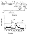
- the inventors have discovered that SBS events can be prevented by using the apparatus shown in Figure 19 .
- the seed laser 192 is preferably the seed laser 382.
- the reflector 196 is preferably the reflector 384.
- the amplifier 193 is preferably the amplifier 383.
- the apparatus 190 comprised a depolarizer 191, isolators 186, a pre-amplifier 192 pumped by a pump 199, and the power amplifier 193 pumped by a pump 194.
- the controller 174 controlled the light source 172, and the pumps 199 and 194.
- the seed laser 192 was a single transverse-mode Fabry-Perot semiconductor laser that emitted approximately 50 to 100 longitudinal modes at a centre wavelength of approximately 1060nm.
- the reflector 196 was a fibre Bragg grating having a bandwidth of approximately 2nm and which was chirped. Its reflectivity was around 4%.
- the depolarizer 191 comprised two lengths of polarization maintaining fibre spliced at 45 degrees to each other. Use of the depolarizer 191 is preferable in many materials processing applications (but not all) to reduce variations in processing conditions caused by polarization fluctuations. It is therefore important that the seed laser 192 has sufficient optical bandwidth to enable its emission to be depolarized.
- the isolators 186 were commercial off-the-shelf isolators chosen to prevent amplified spontaneous emission from being redirected back into the seed laser 192,
- the preamplifier 192 and power amplifier 193 were ytterbium-doped cladding pumped fibre amplifiers.
- the pumps 194,199 comprised many single-emitter semiconductor laser diodes that were combined together.
- a tap coupler 197 was provided in order to monitor backward traveling optical radiation from the power amplifier 193.
- the tap coupler 197 and back reflection detector 198 were included for diagnostic purposes, and need not form part of a wished apparatus.
- the seed laser 192 is pulsed to provide 10ns to 250ns pulses 175 at frequencies between 1kHz and 500kHz.
- the peak power from the seed laser is approximately 300mW
- the peak power from the preamplifier 192 is approximately 100W
- the peak power from the power amplifier 193 is approximately 10 to 15kW.
- a failure mechanism is characterized by a short length (up to 100mm) of ytterbium-doped optical fibre within the power amplifier 193 destructing. The short length of fiber turns into a white powder.
- Another failure mechanism is a fusion splice at an end of the power amplifier failing.
- Figure 20 shows the optical power 201 of the forward going pulse 1719 (measured at the output of the power amplifier 193) and the output power 202 as measured by the back reflection detector 198 in normal operation.
- the optical powers 201 and 202 are plotted on different scales since the output power 201 has a much higher power than the optical power 202.
- the output power 202 comprises a first reflection 203 and a second reflection 204.
- the first reflection 203 originates from the splice (not shown) between the tap 197 and the power amplifier 193.
- the second reflection 204 originates from a reflection from the output of the fiber optic cable 1711.
- the pulse shapes as shown in Figure 20 are typical of the vast majority of pulses emerging from the apparatus 190.
- Figure 21 shows two examples of backward traveling pulses 211, 212.
- the pulses 211 and 212 comprise the optical powers 203 and 204 as before, but also contain additional spikes 213 and 214. These additional spikes 213 and 214 occur infrequently and are random in both occurrence and in magnitude.
- the frequency of occurrence can be varied by changing the operating conditions of the seed laser 192 (such as temperature, drive current and pulse shape). At a pulse repetition frequency of 25kHz, the additional spikes have been observed at a rate of between approximately 1 measured over a weekend through to 30,000 measured over a five minute period. Additionally, the rate of occurrence can be varied by using different seed lasers 192 supplied by different or the same manufacturer. Although additional spikes 213, 214 were observed in the backward traveling direction, no evidence is observable in the forward going pulse shape 201. It is believed that the spikes 213 and 214 are evidence of stimulated Brillouin scattering (SBS).
- SBS stimulated Brillouin scattering
- FIG 22 shows an example of a giant pulse 221 superimposed on a normal looking pulse 201 that occurred in the forward direction.
- a related pulse 222 measured by the back reflection detector 198 has a complex shape and has a magnitude several orders higher than the pulse 202 shown in Figure 20 . Indeed the optical powers 203 and 204 are not visible on this scale.
- the pulse 222 has a spike 223, a trailing edge 224, and a dip 225. These data were obtained by setting up the apparatus 190 so that the backward spikes 213 and 214 were occurring at around 100Hz. At this repetition frequency, the giant pulses 221 and associated pulses 222 were observed occurring at around 1 every five minutes. In other words, the giant pulses 221 are much more infrequent than the backward traveling pulses 213 and 214, and occur on a random basis.
- the backward traveling pulse 222 has sufficient energy to pump a forward going pulse via SBS. This results in the giant pulse 221 in the forward going direction which therefore extracts energy from the backward traveling pulse 222 resulting in the dip 225. All the above pulses are additionally amplified by the active gain medium in the power amplifier 193.
- the amplitude 226 of the giant pulse 221 shown is approximately twice the amplitude 227 of the pulse 201 (without the giant pulse 221 superimposed).
- the amplitude 226 varies randomly, and can be several times the amplitude 227 of the pulse 201. It is believed that the amplitude of the giant pulse 221 can be sufficient to exceed the optical damage threshold of the fiber within the power amplifier 193, and it is this, possibly with additional energy caused by the acoustic wave that is associated with SBS propagation, that caused the random and unpredictable catastrophic failures described above.
- this explanation is just a theory and our attempt to describe a possible failure mechanism is not intended to limit the scope of the invention.
- Figure 23 shows a typical spectrum 230 from the seed laser 192.
- the centre wavelength 231 is approximately 1062nm, and it is an overall bandwidth 232 of approximately 6nm.
- the spectrum 230 comprises approximately 150 laser lines 233 (not all shown) that are separated by approximately 0.045nm.
- the spectrum 230 comprises three families 234, 235, 236 of the laser lines 233 that have been observed to vary as the pulse 1719 evolves.
- the first family 234 is dominant at the first stages of the pulse duration 177 (during which the pulse 1719 chirps), and the central family 235 becomes more dominant thereafter.
- Figure 25 shows the design of the fibre Bragg grating 250 (not shown) used as the reflector 196 in the apparatus of Figure 19 .
- Figure 25 shows the reflectivity 251 (left axis) and group delay 252 (right axis) plotted as a function of wavelength 253.
- the group delay 252 is offset from zero. The offset is arbitrary as the group delay 252 depends upon the position at which it is measured. There is noise on both reflectivity 251 and group delay 252 curves which is mathematical in nature owing to computations involving very small numbers.
- the grating 250 is chirped with a bandwidth 255 of approximately 4nm. Its central wavelength 254 was designed to be 1061nm, aligned approximately within the central family 235 of Figure 23 .
- Figure 26 shows the measured reflectivity 261 of the grating 250.
- the central wavelength 262 is approximately 1060.7nm, and the bandwidth 263 is approximately 2nm.
- the bandwidth 263 is less than the design bandwidth 255 because of detuning effects in the manufacture of the grating 250. These effects are known by those skilled in the art of fiber grating manufacture. Techniques to design and manufacture such gratings are described in United States Patent nos. 6,445,852 and 6,072,926 , which patents are incorporated herein by reference.
- Narrowband gratings (bandwidth less than around 0.5nm, and often less than around 0.1nm) are often incorporated into laser diode packaging in order to lock the emission wavelength, to prevent mode partition noise, to reduce the amplitude of side modes (so-called side-mode suppression), and/or to narrow the linewidth. All such purposes would tend to result in a more stable emission which (it is believed) would promote SBS and increase the frequency of occurrence of the giant pulses, and would therefore not avoid the catastrophic failures of the apparatus 190.
- Figure 24 shows the spectrum 240 of the laser diode 2 measured with the grating 250 in place.
- the central wavelength 241 is approximately 1061nm.
- the spectrum 240 has a bandwidth 242 that is less than the bandwidth 232 of the spectrum 230.
- the bandwidth 242 is approximately 2nm, being determined by the optical feedback from the grating 250. In accordance with the teaching of US patent no. 6,433,306 , such a narrowing of the bandwidth would be expected to degrade the SBS performance.
- the use of the grating 250 has eliminated both the backward traveling random pulses 213 and 214, and also the associated and more random forward-traveling giant pulses 221.
- the apparatus 190 has been found to be failure free.
- the grating 250 has shown to provide reliable operation for pulsed lasers having at least 10% of the optical radiation in a single transverse mode and having peak powers in the range 1kW to 40kW. It is believed that higher peak powers can be achieved up to 100kW or more without SBS causing a problem.
- the grating 250 has destabilized the seed laser 192 (in this case a laser diode). That is, the individual laser lines 233 are broadened, chirped or are being modulated such that the conditions for SBS generation in the power amplifier 193 are avoided.
- Other methods to avoid SBS generation would be to implement the reflector 196 as a broadband reflector such as a partially reflecting mirror or surface, which can be coupled in via an optical fiber coupler, or a grating having a bandwidth greater than 0.5nm, preferably greater than 1nm, and more preferably greater than 2nm.
- the grating 250 is preferably chirped, but does not necessarily need to be so.
- the chirped grating 250 will provide a wavelength dependent effective external cavity length which is believed to contribute further to the spectral broadening of the seed laser 192.
- the chirped grating 250 is preferably inscribed in a polarization maintaining optical fiber with its polarization axes aligned or at an angle to the polarization axes of the seed laser 192 polarization maintaining fiber pigtail.
- the grating 250 can equally be inscribed in a non-polarization maintaining fiber.
- the seed laser 192 pigtail need not necessarily be polarization maintaining fiber.
- the reflector 196 can be positioned to reflect laser radiation into either the front or back facets (not shown) of the seed laser 192.
- the reflector 196 can also comprise dielectric coatings.
- the reflectivity of the reflector 196 can be between approximately 0.1% and 10%. Results showing no pulses 213, 214 have been obtained with reflectivities as high as 34%; however pulse distortion was observed at these levels. Preferably the reflectivity is approximately 2% to 6%. The exact number will depend upon the specific laser diode being used and can be found by experimentation. It is believed that the reflectivity of the reflector 196 should be higher than the reflectivity used in the front facet of the seed laser 192. It is also believed that the bandwidth of the seed laser 192 is preferably comparable to or smaller than the bandwidth of the reflector 196. This was not the case in the experiments described above, and therefore the operating conditions (temperature and drive current) of the seed laser 192 needed to be set up for different batches of seed lasers 192.
- the bandwidth of the grating reflector 196 can be increased to include the entire bandwidth of the seed laser 192 and manufacturing tolerances of the emission wavelengths. Note also, the provision of the tap 197 enables such a set up since the complete absence of backward traveling pulses is a reliable indication of reliable operation.
- the grating 250 was positioned between 40cm and 1m from the seed laser 192. No difference in performance was observed. It is therefore believed that the exact position is not critical, provided that the distance is not so large that there is insufficient time to stabilize the seed laser 192 with reflective feedback.
- the seed laser 192 and the pumps 199 and 194 are controlled by the controller 25. Further information on the use of the controller to control the pulse shape of the optical pulses 1719, and the application and use of the apparatus in materials processing is described below.
- the preamplifier 192 and power amplifier 193 can be core-pumped or cladding pumped.
- the preamplifier 192 can be a core-pumped preamplifier.
- a core-pumped preamplifier is a shorter device than a cladding-pumped preamplifier and is more efficient.
- the preamplifier 192 can be a cladding-pumped preamplifier. This is preferable in order to reduce cost.
- the power amplifier 193 is cladding pumped. Such arrangements provide for efficient devices that can be produced with low cost.
- the design and construction of cladding pumped amplifiers are described in United States Patent no. 6,826,335 , which is hereby incorporated herein by reference.
- the optical fibres contained within the preamplifier 192 and power amplifier 193 can each be solid core fibres or so-called holey fibres. They are preferably doped with rare-earth dopant such as ytterbium, erbium, neodymium, holmium, thulium or praseodymium. Preferably the optical fibres are resistant to photodarkening. Such fibres are described in co-pending patent application attorney docket number SO01-P20 which is hereby incorporated herein by reference.
- Figure 19 can be used to replace the light source 172 and amplifier 173 of Figure 19 .
- the controller 174 controls the seed laser 192 and the pumps 194 that pump the pre-amplifier 192 and amplifier 193 such that the average power 178 and peak power 179 are maintained at levels sufficient to process materials 1714 over a range of pulse repetition frequencies 176.
- Figure 27 shows output pulses 271, 272, 273 and 274 versus time 275 for pulse repetition rates of 115kHz, 46kHz, 30kHz and 24kHz respectively.
- the corresponding optical pulses 175 emitted by the seed laser 192 are shown as pulses 281, 282, 283 and 284 respectively in Figure 28 .
- Output pulses 271 to 274 and optical pulses 281 to 284 are reproduced in Figures 29 and 30 respectively where the respective pulses are superimposed.
- Figure 31 shows the variation of peak power 179 and pulse energy 1710 with pulse repetition frequency 176.
- the peak power 179 is maintained above 5kW and the pulse energy 1710 is maintained above 0.1mJ for pulse repetition frequencies 176 between 24kHz and 115kHz.
- the average power 178 is the product of pulse repetition frequency 176 and pulse energy 1710, the average power 178 can be seen to be greater than approximately 10W for pulse repetition frequencies 176 between 24kHz and 115kHz.
- the results shown in Figures 27 to 31 are very significant because it has proven possible to achieve peak powers of 5kW with pulse energies of 0.1 mJ at a pulse-repetition frequency of greater than 100kHz with only two stages of amplification.
- the MOPA 190 will have great utility in increasing processing speeds compared to other fibre-optic pulse laser systems of comparable average output power 178.
- Figure 32 shows the output power 320 from the MOPA 190 with increased power from the pumps 194. A peak power of 35kW is achieved with a pulse width of around 10ns (measured at half the peak power).
- Figure 33 shows the optical spectrum 331 of the pulse which is shown plotted versus wavelength 332.
- the signal wavelength 333 of the pulse from the seed laser 192 was approximately 1062nm. There is a significant proportion of the power at wavelengths longer than the signal wavelength 333, which power has been wavelength shifted due to non-linear processes such as stimulated Raman scattering.
- the output power 321 was measured using an optical filter that attenuated wavelengths greater than 1070nm. It is seen from Figures 32 and 33 that output powers greater than approximately 8kW are shifted in wavelength.
- the 8kW output power can be defined as a non-linear threshold 322.
- Use of the MOPA 190 for the processing of materials may thus require the use of wide band optics within the processing head 1712 of Figure 17 .
- wide band optics it is meant optics that can transmit and focus signal wavelengths having a bandwidth greater than approximately 100nm. Nevertheless, the MOPA 190 operating in this mode has great utility for the processing of materials that require peak powers 179 greater than around 8kW.
- the controller 174 can be used to reduce the proportion of the output pulses 1719 that is wavelength converted by reducing the power emitted by the pumps 194 and 199, or by controlling the shape of the output pulses 1719.
- the proportion that is wavelength converted can be reduced to less than 50%, and preferably less than 10%.
- Preferably substantially none of the output pulses 1719 are wavelength converted over a wide range of pulse repetition frequencies 176 such as was demonstrated by reference to Figures 27 to 31 .
- the control function of the controlled 174 can be effected either by open loop control (for example achieved through experimentation and characterization), or be closed loop control in which a measurement of power (average power or peak power or a wavelength shifted power) is taken from a point within the MOPA 190 (for example at the input or output of the amplifier 193 or elsewhere), compared with a desired value, and the difference between the measurement and the desired value used to modify the control function provided by the controller 174.
- open loop control for example achieved through experimentation and characterization
- a measurement of power average power or peak power or a wavelength shifted power
- Figures 34 to 37 show the effect of varying the pulse repetition frequency (prf) 176 and pulse width 177 has on the shape of the output pulse 1719 in a MOPA 190. All four figures are plotted on the same scales with the output power being plotted in arbitrary units.
- the controller 174 controlled the pumps 194 and 199 such that the average power 178 was maintained at 12W.
- the controller 174 also set the pulse repetition frequency 176 to its desired value.
- the controller 174 then varied the pulse width 177 (ie the overall pulse width of each pulse 1719) to set the peak power 179 at desired values.
- Figure 34 shows the output power 340 versus time 275 measured with a pulse repetition frequency 176 of 25kHz, a pulse energy 1710 of 0.6mJ, and an average power 178 of 12W.
- the pulse width 343 (ie the overall pulse width as controlled by the controller 174) was approximately 200ns.
- the output power 340 has a peak power 341, and a full width half maxima pulse width 342 of approximately 35ns.
- Figure 35 shows the output power 350 and 351 versus time 275 measured for two different pulse widths 355 and 356 respectively.
- the pulse repetition frequency 176 was 50kHz
- the pulse energy 1710 was 0.24mJ
- the average power 178 was 12W.
- the full width half maxima pulse width 354 for the output power 350 was approximately 35ns.
- the peak powers 352, 353 reduce with increasing pulse widths 355, 356.
- Figure 36 shows the output power 360, 361 and 362 versus time 275 measured for three different pulse widths 367, 368 and 369 respectively.
- the pulse repetition frequency 176 was 100kHz
- the pulse energy 1710 was 0.12mJ
- the average power 178 was 12W.
- the full width half maxima pulse width 126 for the output power 360 was approximately 35ns.
- the peak powers 363, 364, 365 reduce with increasing pulse widths 367, 368 and 369.
- Figure 37 shows the output power 370 and 371 versus time 275 measured for two different pulse widths 375 and 376 respectively.
- the pulse repetition frequency 176 was 200kHz
- the pulse energy 1710 was 0.06mJ
- the average power 178 was 12W.
- the full width half maxima pulse width 374 for the output power 370 was approximately 20ns.
- the peak powers 372 and 373 reduce with increasing pulse widths 375 and 376.
- peak power 179 has been maintained above the 5kW level over a range of pulse repetition frequencies 176 from 1Hz to 200kHz, while providing pulse energies 1710 in excess of 0.1mJ.
- the peak power 179 has been maintained above the 3kW level over a range of pulse repetition frequencies 176 from 1Hz to 500kHz, while providing pulse energies 1710 in excess of 0.04mJ.
- both these results were achieved without any evidence of SBS and with only two amplification stages.
- the invention can also be in the form of a materials processing machine (eg one for cutting, welding, drilling, marking or processing materials) comprising one or more of the lasers and controllers described above.
- a materials processing machine eg one for cutting, welding, drilling, marking or processing materials
- the present invention extends to the above mentioned features taken singly or in any combination.
Applications Claiming Priority (5)
| Application Number | Priority Date | Filing Date | Title |
|---|---|---|---|
| US79945606P | 2006-05-11 | 2006-05-11 | |
| US81216406P | 2006-06-09 | 2006-06-09 | |
| US81943906P | 2006-07-07 | 2006-07-07 | |
| US83497406P | 2006-07-31 | 2006-07-31 | |
| EP07732735.1A EP2016652B1 (fr) | 2006-05-11 | 2007-05-10 | Appareil de rayonnement optique |
Related Parent Applications (2)
| Application Number | Title | Priority Date | Filing Date |
|---|---|---|---|
| EP07732735.1A Division EP2016652B1 (fr) | 2006-05-11 | 2007-05-10 | Appareil de rayonnement optique |
| EP07732735.1A Division-Into EP2016652B1 (fr) | 2006-05-11 | 2007-05-10 | Appareil de rayonnement optique |
Publications (2)
| Publication Number | Publication Date |
|---|---|
| EP2763247A2 true EP2763247A2 (fr) | 2014-08-06 |
| EP2763247A3 EP2763247A3 (fr) | 2014-09-17 |
Family
ID=38694261
Family Applications (2)
| Application Number | Title | Priority Date | Filing Date |
|---|---|---|---|
| EP14165950.8A Withdrawn EP2763247A3 (fr) | 2006-05-11 | 2007-05-10 | Appareil pour fournir un rayonnement optique |
| EP07732735.1A Active EP2016652B1 (fr) | 2006-05-11 | 2007-05-10 | Appareil de rayonnement optique |
Family Applications After (1)
| Application Number | Title | Priority Date | Filing Date |
|---|---|---|---|
| EP07732735.1A Active EP2016652B1 (fr) | 2006-05-11 | 2007-05-10 | Appareil de rayonnement optique |
Country Status (7)
| Country | Link |
|---|---|
| US (3) | US7936796B2 (fr) |
| EP (2) | EP2763247A3 (fr) |
| JP (2) | JP5467864B2 (fr) |
| KR (1) | KR101383197B1 (fr) |
| CN (2) | CN101517848B (fr) |
| CA (1) | CA2652006C (fr) |
| WO (1) | WO2007132182A2 (fr) |
Families Citing this family (36)
| Publication number | Priority date | Publication date | Assignee | Title |
|---|---|---|---|---|
| WO2007132182A2 (fr) * | 2006-05-11 | 2007-11-22 | Spi Lasers Uk Limited | Appareil de rayonnement optique |
| GB2444091A (en) * | 2006-11-24 | 2008-05-28 | Gsi Group Ltd | A Laser Amplifier |
| US7450813B2 (en) | 2006-09-20 | 2008-11-11 | Imra America, Inc. | Rare earth doped and large effective area optical fibers for fiber lasers and amplifiers |
| US8055115B2 (en) * | 2007-07-05 | 2011-11-08 | Coractive High-Tech Inc. | Optically active glass and optical fiber with reduced photodarkening and method for reducing photodarkening |
| IN2010KN00199A (fr) * | 2007-07-16 | 2015-08-28 | Coractive High Tech Inc | |
| JP2009290203A (ja) * | 2008-04-30 | 2009-12-10 | Sumitomo Electric Ind Ltd | 光増幅モジュールおよびレーザ光源装置 |
| WO2010016287A1 (fr) * | 2008-08-04 | 2010-02-11 | 株式会社フジクラ | Fibre optique dopée à l'ytterbium, laser à fibre et amplificateur à fibre |
| FR2935554B1 (fr) * | 2008-09-02 | 2012-04-13 | Centre Nat Rech Scient | Dispositif laser a fibre de forte puissance moyenne |
| JP5415553B2 (ja) * | 2008-11-28 | 2014-02-12 | エヌケイティー フォトニクス アクティーゼルスカブ | 改良されたクラッドポンプ光導波路 |
| WO2010065788A1 (fr) * | 2008-12-04 | 2010-06-10 | Imra America, Inc. | Fibres optiques hautement dopées aux terres rares pour lasers à fibre et amplificateurs à fibre |
| JP5405904B2 (ja) * | 2009-05-28 | 2014-02-05 | 株式会社メガオプト | Mopa光源 |
| US8526472B2 (en) * | 2009-09-03 | 2013-09-03 | Axsun Technologies, Inc. | ASE swept source with self-tracking filter for OCT medical imaging |
| US8670129B2 (en) | 2009-09-03 | 2014-03-11 | Axsun Technologies, Inc. | Filtered ASE swept source for OCT medical imaging |
| US8934509B2 (en) * | 2009-11-23 | 2015-01-13 | Lockheed Martin Corporation | Q-switched oscillator seed-source for MOPA laser illuminator method and apparatus |
| JP5324417B2 (ja) * | 2009-12-25 | 2013-10-23 | 旭化成エレクトロニクス株式会社 | 駆動用ドライバ、駆動用アンプおよび情報機器 |
| WO2012031221A1 (fr) * | 2010-09-02 | 2012-03-08 | Ofs Fitel, Llc | Cavité laser présentant un bruit faible |
| JP6002453B2 (ja) * | 2012-06-06 | 2016-10-05 | 三菱電線工業株式会社 | 希土類添加ダブルクラッドファイバ |
| JP6037711B2 (ja) * | 2012-08-08 | 2016-12-07 | 株式会社フジクラ | ファイバレーザ装置 |
| JP2014059294A (ja) * | 2012-08-21 | 2014-04-03 | Canon Inc | X線導波路及びx線測定システム |
| US8970935B2 (en) | 2012-09-27 | 2015-03-03 | The Johns Hopkins University | High energy fiber laser modulator |
| JP6077263B2 (ja) * | 2012-10-16 | 2017-02-08 | 古河電気工業株式会社 | レーザ装置 |
| JP6090780B2 (ja) * | 2013-01-24 | 2017-03-08 | 国立研究開発法人産業技術総合研究所 | 高パワーインコヒーレント光発生装置 |
| CN105119134A (zh) * | 2014-03-13 | 2015-12-02 | 恩耐激光技术有限公司 | 用于种子可中止的脉冲光纤激光放大器的快速选通的算法 |
| CN105281186B (zh) * | 2015-11-19 | 2018-06-22 | 北京工业大学 | 侧面双向泵浦熔融型耦合器及其制作方法 |
| GB201521214D0 (en) * | 2015-12-01 | 2016-01-13 | Spi Lasers Uk Ltd | Apparatus for providing optical radiation |
| US10348050B2 (en) | 2016-02-04 | 2019-07-09 | Lawrence Livermore National Security, Llc | Nd3+fiber laser and amplifier |
| US10033148B2 (en) | 2016-02-04 | 2018-07-24 | Lawrence Livermore National Security, Llc | Waveguide design for line selection in fiber lasers and amplifiers |
| US10490969B2 (en) * | 2016-07-15 | 2019-11-26 | Fraunhofer-Gesellschaft Zur Foerderung Der Angewandten Forschung E. V. | Active stabilization of mode instabilities in optical waveguides |
| US9985414B1 (en) | 2017-06-16 | 2018-05-29 | Banner Engineering Corp. | Open-loop laser power-regulation |
| EP3646418A2 (fr) * | 2017-06-25 | 2020-05-06 | Abacus Laser GmbH | Système laser et procédé permettant de faire fonctionner un système laser |
| GB201719629D0 (en) * | 2017-11-24 | 2018-01-10 | Spi Lasers Uk Ltd | Apparatus for providing optical radiation |
| CN109570148A (zh) * | 2018-11-08 | 2019-04-05 | 中国科学院半导体研究所 | 直连空压机的激光清洗一体机 |
| GB201903633D0 (en) * | 2019-03-15 | 2019-05-01 | Spi Lasers Uk Ltd | Apparatus for providing optical radiation |
| JP7414744B2 (ja) | 2020-02-21 | 2024-01-16 | トヨタ自動車株式会社 | 増幅ファイバ及びレーザ光出射装置 |
| EP3869636B1 (fr) * | 2020-02-21 | 2024-03-13 | Toyota Jidosha Kabushiki Kaisha | Fibre d'amplification et appareil d'émission de faisceau laser |
| US11609116B2 (en) | 2020-08-27 | 2023-03-21 | Banner Engineering Corp | Open-loop photodiode gain regulation |
Citations (21)
| Publication number | Priority date | Publication date | Assignee | Title |
|---|---|---|---|---|
| US4274854A (en) | 1978-01-13 | 1981-06-23 | Bell Telephone Laboratories, Incorporated | Polarization-preserving optical fiber |
| US4426129A (en) | 1980-01-11 | 1984-01-17 | Hitachi, Ltd. | Optical fiber and method of producing the same |
| US4787927A (en) | 1985-08-13 | 1988-11-29 | National Research Development Corporation | Fabrication of optical fibers |
| US4815079A (en) | 1987-12-17 | 1989-03-21 | Polaroid Corporation | Optical fiber lasers and amplifiers |
| US4826288A (en) | 1987-04-09 | 1989-05-02 | Polaroid Corporation, Patent Department | Method for fabricating optical fibers having cores with high rare earth content |
| US5047076A (en) | 1988-12-07 | 1991-09-10 | Sip - Societa Italiana Per L-Esercizio Delle Telecomunicazioni P.A. | Method of fabricating optical fibres by solution-doping |
| US5627848A (en) | 1995-09-05 | 1997-05-06 | Imra America, Inc. | Apparatus for producing femtosecond and picosecond pulses from modelocked fiber lasers cladding pumped with broad area diode laser arrays |
| US5696782A (en) | 1995-05-19 | 1997-12-09 | Imra America, Inc. | High power fiber chirped pulse amplification systems based on cladding pumped rare-earth doped fibers |
| US5818630A (en) | 1997-06-25 | 1998-10-06 | Imra America, Inc. | Single-mode amplifiers and compressors based on multi-mode fibers |
| US5854865A (en) | 1995-12-07 | 1998-12-29 | The United States Of America As Represented By The Secretary Of The Navy | Method and apparatus for side pumping an optical fiber |
| US5864644A (en) | 1997-07-21 | 1999-01-26 | Lucent Technologies Inc. | Tapered fiber bundles for coupling light into and out of cladding-pumped fiber devices |
| US6072926A (en) | 1995-05-16 | 2000-06-06 | Cole; Martin | Optical waveguide grating |
| US6275512B1 (en) | 1998-11-25 | 2001-08-14 | Imra America, Inc. | Mode-locked multimode fiber laser pulse source |
| US6433306B1 (en) | 1997-02-19 | 2002-08-13 | Jds Uniphase Corp. | Semiconductor laser high power amplifier system for materials processing |
| US6445852B1 (en) | 2000-08-01 | 2002-09-03 | University Of Southampton | Optical fiber grating |
| US6496301B1 (en) | 2000-03-10 | 2002-12-17 | The United States Of America As Represented By The Secretary Of The Navy | Helical fiber amplifier |
| US6614975B2 (en) | 1998-07-03 | 2003-09-02 | University Of Southampton | Optical fiber and optical fiber device |
| US6731837B2 (en) | 2000-11-28 | 2004-05-04 | Keopsys, Inc. | Optical fiber amplifiers and lasers and optical pumping devices therefor and methods of fabricating same |
| US6826335B1 (en) | 1909-04-30 | 2004-11-30 | The University Of Southampton | Multi-fibre arrangements for high power fibre lasers and amplifiers |
| US6885663B2 (en) | 1999-12-17 | 2005-04-26 | Siemens Aktiengesellschaft | Time/space switching component with multiple functionality |
| US6954575B2 (en) | 2001-03-16 | 2005-10-11 | Imra America, Inc. | Single-polarization high power fiber lasers and amplifiers |
Family Cites Families (38)
| Publication number | Priority date | Publication date | Assignee | Title |
|---|---|---|---|---|
| GB9010943D0 (en) | 1990-05-16 | 1990-07-04 | British Telecomm | Wave-guiding structure with lasing properties |
| US5260823A (en) * | 1990-05-21 | 1993-11-09 | University Of Southampton | Erbium-doped fibre amplifier with shaped spectral gain |
| US5115338A (en) * | 1990-05-30 | 1992-05-19 | At&T Bell Laboratories | Multi-stage optical amplifier |
| US5225925A (en) * | 1991-01-23 | 1993-07-06 | Amoco Corporation | Sensitized erbium fiber optical amplifier and source |
| US5516784A (en) * | 1991-08-13 | 1996-05-14 | Schering Corporation | Anti-HIV (AIDS) agents |
| US5659559A (en) * | 1994-06-28 | 1997-08-19 | Sdl, Inc. | Apparatus for generating a stabilized laser source |
| US5530709A (en) * | 1994-09-06 | 1996-06-25 | Sdl, Inc. | Double-clad upconversion fiber laser |
| JP3379052B2 (ja) * | 1994-09-26 | 2003-02-17 | 富士通株式会社 | 波長多重光増幅装置及び光波長多重伝送システム及び光波長多重伝送方法 |
| US5701319A (en) * | 1995-10-20 | 1997-12-23 | Imra America, Inc. | Method and apparatus for generating ultrashort pulses with adjustable repetition rates from passively modelocked fiber lasers |
| JPH10221656A (ja) * | 1997-02-06 | 1998-08-21 | Nec Corp | 光送信器及び光送信方法 |
| US5892615A (en) * | 1997-03-17 | 1999-04-06 | Sdl, Inc. | Output power enhancement in optical fiber lasers |
| US6181463B1 (en) * | 1997-03-21 | 2001-01-30 | Imra America, Inc. | Quasi-phase-matched parametric chirped pulse amplification systems |
| EP1658663A4 (fr) * | 1997-03-21 | 2009-11-11 | Imra America Inc | Amplificateur a fibre optique haute energie pour impulsions picoseconde-nanoseconde destinees a des applications de traitement de materiaux hautes performances |
| US5937134A (en) * | 1997-08-07 | 1999-08-10 | Lucent Technologies Inc. | Cladding pumped fiber lasers |
| US6154598A (en) * | 1997-12-22 | 2000-11-28 | Polaroid Corporation | Laser composition for preventing photo-induced damage |
| JP4011175B2 (ja) * | 1998-02-06 | 2007-11-21 | 浜松ホトニクス株式会社 | 光ファイバレーザ装置及びレーザ加工装置 |
| JP3097662B2 (ja) * | 1998-06-08 | 2000-10-10 | 日本電気株式会社 | 光ファイバ増幅器 |
| US6525872B1 (en) * | 1999-02-11 | 2003-02-25 | Jds Uniphase Corporation | Fiber grating-stabilized, semiconductor pump source |
| US6340806B1 (en) * | 1999-12-28 | 2002-01-22 | General Scanning Inc. | Energy-efficient method and system for processing target material using an amplified, wavelength-shifted pulse train |
| JP2001257422A (ja) | 2000-03-10 | 2001-09-21 | Sumitomo Electric Ind Ltd | 半導体レーザモジュール |
| JP2001326404A (ja) * | 2000-05-16 | 2001-11-22 | Fujikura Ltd | 希土類添加光ファイバ |
| US6584246B1 (en) * | 2000-07-05 | 2003-06-24 | Litton Systems, Inc. | Source, system and method for generating amplified stimulated emission using a coupler mechanism |
| JP4531941B2 (ja) * | 2000-07-14 | 2010-08-25 | 古河電気工業株式会社 | 光増幅用光ファイバ |
| US6636347B1 (en) * | 2000-11-08 | 2003-10-21 | Corning Incorporated | Phosphorus-silicate fibers suitable for extended band amplification |
| DE10059314B4 (de) * | 2000-11-29 | 2018-08-02 | Tesat-Spacecom Gmbh & Co.Kg | Lichtleitende Faser und Verfahren zum Herstellen einer lichtleitenden Faser |
| EP1241751B1 (fr) * | 2001-03-13 | 2004-06-02 | JDS Uniphase Corporation | Diode laser à haute puissance à mode unique sans un coude |
| KR20020077061A (ko) * | 2001-03-28 | 2002-10-11 | 주식회사 네오텍리서치 | 장파장대역용 이득고정 에르븀첨가 광섬유증폭기 |
| US7065121B2 (en) * | 2001-07-24 | 2006-06-20 | Gsi Group Ltd. | Waveguide architecture, waveguide devices for laser processing and beam control, and laser processing applications |
| JP2003307657A (ja) * | 2002-04-15 | 2003-10-31 | Mitsubishi Cable Ind Ltd | 高出力パルス光用ファイバ及び光増幅装置 |
| EP1614198A4 (fr) * | 2003-03-24 | 2006-09-20 | Bookham Technology Plc | Laser accordable a cavite externe avec longueur de cavite reglable et suppression de saut de mode |
| JP4799810B2 (ja) * | 2003-07-09 | 2011-10-26 | 三菱電線工業株式会社 | ダブルクラッドファイバ及びそれを用いた光増幅方法 |
| JP3923994B2 (ja) * | 2003-07-28 | 2007-06-06 | 日本電信電話株式会社 | ファイバレーザ、自然放出光源及び光ファイバ増幅器 |
| GB0328370D0 (en) * | 2003-12-05 | 2004-01-14 | Southampton Photonics Ltd | Apparatus for providing optical radiation |
| JP3952033B2 (ja) * | 2004-04-02 | 2007-08-01 | 松下電器産業株式会社 | 光増幅ファイバと光増幅方法とレーザ発振方法とレーザ増幅装置とレーザ発振装置とレーザ装置とレーザ加工機 |
| US7590155B2 (en) * | 2004-08-05 | 2009-09-15 | Jian Liu | Hybrid high power laser to achieve high repetition rate and high pulse energy |
| US7062137B2 (en) * | 2004-08-05 | 2006-06-13 | Nufern | Fiber optic article including fluorine |
| JP4825809B2 (ja) * | 2004-12-20 | 2011-11-30 | イムラ アメリカ インコーポレイテッド | 調整可能なグレーティングコンプレッサを備えたパルスレーザ光源 |
| WO2007132182A2 (fr) * | 2006-05-11 | 2007-11-22 | Spi Lasers Uk Limited | Appareil de rayonnement optique |
-
2007
- 2007-05-10 WO PCT/GB2007/001707 patent/WO2007132182A2/fr active Application Filing
- 2007-05-10 CN CN2007800171785A patent/CN101517848B/zh active Active
- 2007-05-10 CN CN201110059565.3A patent/CN102157887B/zh active Active
- 2007-05-10 CA CA2652006A patent/CA2652006C/fr active Active
- 2007-05-10 EP EP14165950.8A patent/EP2763247A3/fr not_active Withdrawn
- 2007-05-10 EP EP07732735.1A patent/EP2016652B1/fr active Active
- 2007-05-10 JP JP2009508486A patent/JP5467864B2/ja active Active
- 2007-05-10 KR KR1020087030028A patent/KR101383197B1/ko active IP Right Grant
- 2007-05-11 US US11/803,036 patent/US7936796B2/en active Active
-
2011
- 2011-04-29 US US13/098,234 patent/US20110206074A1/en not_active Abandoned
- 2011-05-17 US US13/109,630 patent/US20110216790A1/en not_active Abandoned
-
2014
- 2014-01-27 JP JP2014012311A patent/JP2014112705A/ja active Pending
Patent Citations (21)
| Publication number | Priority date | Publication date | Assignee | Title |
|---|---|---|---|---|
| US6826335B1 (en) | 1909-04-30 | 2004-11-30 | The University Of Southampton | Multi-fibre arrangements for high power fibre lasers and amplifiers |
| US4274854A (en) | 1978-01-13 | 1981-06-23 | Bell Telephone Laboratories, Incorporated | Polarization-preserving optical fiber |
| US4426129A (en) | 1980-01-11 | 1984-01-17 | Hitachi, Ltd. | Optical fiber and method of producing the same |
| US4787927A (en) | 1985-08-13 | 1988-11-29 | National Research Development Corporation | Fabrication of optical fibers |
| US4826288A (en) | 1987-04-09 | 1989-05-02 | Polaroid Corporation, Patent Department | Method for fabricating optical fibers having cores with high rare earth content |
| US4815079A (en) | 1987-12-17 | 1989-03-21 | Polaroid Corporation | Optical fiber lasers and amplifiers |
| US5047076A (en) | 1988-12-07 | 1991-09-10 | Sip - Societa Italiana Per L-Esercizio Delle Telecomunicazioni P.A. | Method of fabricating optical fibres by solution-doping |
| US6072926A (en) | 1995-05-16 | 2000-06-06 | Cole; Martin | Optical waveguide grating |
| US5696782A (en) | 1995-05-19 | 1997-12-09 | Imra America, Inc. | High power fiber chirped pulse amplification systems based on cladding pumped rare-earth doped fibers |
| US5627848A (en) | 1995-09-05 | 1997-05-06 | Imra America, Inc. | Apparatus for producing femtosecond and picosecond pulses from modelocked fiber lasers cladding pumped with broad area diode laser arrays |
| US5854865A (en) | 1995-12-07 | 1998-12-29 | The United States Of America As Represented By The Secretary Of The Navy | Method and apparatus for side pumping an optical fiber |
| US6433306B1 (en) | 1997-02-19 | 2002-08-13 | Jds Uniphase Corp. | Semiconductor laser high power amplifier system for materials processing |
| US5818630A (en) | 1997-06-25 | 1998-10-06 | Imra America, Inc. | Single-mode amplifiers and compressors based on multi-mode fibers |
| US5864644A (en) | 1997-07-21 | 1999-01-26 | Lucent Technologies Inc. | Tapered fiber bundles for coupling light into and out of cladding-pumped fiber devices |
| US6614975B2 (en) | 1998-07-03 | 2003-09-02 | University Of Southampton | Optical fiber and optical fiber device |
| US6275512B1 (en) | 1998-11-25 | 2001-08-14 | Imra America, Inc. | Mode-locked multimode fiber laser pulse source |
| US6885663B2 (en) | 1999-12-17 | 2005-04-26 | Siemens Aktiengesellschaft | Time/space switching component with multiple functionality |
| US6496301B1 (en) | 2000-03-10 | 2002-12-17 | The United States Of America As Represented By The Secretary Of The Navy | Helical fiber amplifier |
| US6445852B1 (en) | 2000-08-01 | 2002-09-03 | University Of Southampton | Optical fiber grating |
| US6731837B2 (en) | 2000-11-28 | 2004-05-04 | Keopsys, Inc. | Optical fiber amplifiers and lasers and optical pumping devices therefor and methods of fabricating same |
| US6954575B2 (en) | 2001-03-16 | 2005-10-11 | Imra America, Inc. | Single-polarization high power fiber lasers and amplifiers |
Non-Patent Citations (1)
| Title |
|---|
| L.L. KOPONEN ET AL.: "Photodarkening in ytterbium-doped silica fibers", PROCEEDINGS OF SPIE, vol. 5990 |
Also Published As
| Publication number | Publication date |
|---|---|
| EP2016652A2 (fr) | 2009-01-21 |
| KR20090015964A (ko) | 2009-02-12 |
| CN101517848B (zh) | 2011-05-11 |
| CA2652006C (fr) | 2017-05-30 |
| US7936796B2 (en) | 2011-05-03 |
| CA2652006A1 (fr) | 2007-11-22 |
| CN102157887B (zh) | 2014-03-26 |
| US20110216790A1 (en) | 2011-09-08 |
| CN102157887A (zh) | 2011-08-17 |
| EP2763247A3 (fr) | 2014-09-17 |
| WO2007132182A4 (fr) | 2009-07-09 |
| JP5467864B2 (ja) | 2014-04-09 |
| CN101517848A (zh) | 2009-08-26 |
| US20090016387A1 (en) | 2009-01-15 |
| US20110206074A1 (en) | 2011-08-25 |
| JP2014112705A (ja) | 2014-06-19 |
| WO2007132182A2 (fr) | 2007-11-22 |
| EP2016652B1 (fr) | 2014-06-18 |
| WO2007132182A3 (fr) | 2009-05-14 |
| KR101383197B1 (ko) | 2014-04-09 |
| JP2009536785A (ja) | 2009-10-15 |
Similar Documents
| Publication | Publication Date | Title |
|---|---|---|
| EP2016652B1 (fr) | Appareil de rayonnement optique | |
| JP5487213B2 (ja) | ファイバレーザ及び増幅器に用いる高度に希土類ドープされた光ファイバ | |
| EP2249443B1 (fr) | Laser à fibre optique | |
| US20050024716A1 (en) | Optical device with immediate gain for brightness enhancement of optical pulses | |
| US20020030881A1 (en) | Optical amplifier and light source | |
| EP2179480A1 (fr) | Dispositif émettant de la lumière avec un verre de phosphosilicate | |
| Grzes et al. | Gain-switched 2-μm fiber laser system providing kilowatt peak-power mode-locked resembling pulses and its application to supercontinuum generation in fluoride fibers | |
| US9647410B2 (en) | Multimode Fabry-Perot fiber laser | |
| US10985519B2 (en) | Active LMA optical fiber and laser system using the same | |
| CN109075522B (zh) | 用于大芯光纤的超短脉冲光纤前置放大器系统 | |
| Khudyakov et al. | High Peak Power Er-doped Tapered Fiber Amplifier. | |
| Le Roux | Methodologies used for increasing the output power of an Erbium doped fiber ring laser | |
| Liu | Pulsed fiber laser at 1 μm wavelength region | |
| Jasapara et al. | Core pumped Erbium fiber nanosecond pulse amplifier generating 360 kW peak power with M2< 1.1 at 1545 nm wavelength | |
| Limpert et al. | 76 W average power femtosecond fiber CPA system | |
| Eidam et al. | Fiber based ultrashort pulse system with kilowatt level average power |
Legal Events
| Date | Code | Title | Description |
|---|---|---|---|
| PUAI | Public reference made under article 153(3) epc to a published international application that has entered the european phase |
Free format text: ORIGINAL CODE: 0009012 |
|
| 17P | Request for examination filed |
Effective date: 20140425 |
|
| AC | Divisional application: reference to earlier application |
Ref document number: 2016652 Country of ref document: EP Kind code of ref document: P |
|
| AK | Designated contracting states |
Kind code of ref document: A2 Designated state(s): AT BE BG CH CY CZ DE DK EE ES FI FR GB GR HU IE IS IT LI LT LU LV MC MT NL PL PT RO SE SI SK TR |
|
| PUAL | Search report despatched |
Free format text: ORIGINAL CODE: 0009013 |
|
| AK | Designated contracting states |
Kind code of ref document: A3 Designated state(s): AT BE BG CH CY CZ DE DK EE ES FI FR GB GR HU IE IS IT LI LT LU LV MC MT NL PL PT RO SE SI SK TR |
|
| RIC1 | Information provided on ipc code assigned before grant |
Ipc: G02B 6/024 20060101ALI20140812BHEP Ipc: H01S 3/16 20060101ALN20140812BHEP Ipc: H01S 3/067 20060101AFI20140812BHEP Ipc: H01S 3/00 20060101ALN20140812BHEP Ipc: H01S 3/0941 20060101ALN20140812BHEP Ipc: H01S 3/094 20060101ALN20140812BHEP Ipc: H01S 5/065 20060101ALI20140812BHEP Ipc: H01S 3/17 20060101ALN20140812BHEP Ipc: H01S 3/10 20060101ALN20140812BHEP |
|
| R17P | Request for examination filed (corrected) |
Effective date: 20150317 |
|
| RBV | Designated contracting states (corrected) |
Designated state(s): AT BE BG CH CY CZ DE DK EE ES FI FR GB GR HU IE IS IT LI LT LU LV MC MT NL PL PT RO SE SI SK TR |
|
| 17Q | First examination report despatched |
Effective date: 20161111 |
|
| STAA | Information on the status of an ep patent application or granted ep patent |
Free format text: STATUS: THE APPLICATION IS DEEMED TO BE WITHDRAWN |
|
| 18D | Application deemed to be withdrawn |
Effective date: 20190416 |