EP2763154B1 - A linkage structure of the moving contact of the modular circuit breaker - Google Patents
A linkage structure of the moving contact of the modular circuit breaker Download PDFInfo
- Publication number
- EP2763154B1 EP2763154B1 EP12834733.3A EP12834733A EP2763154B1 EP 2763154 B1 EP2763154 B1 EP 2763154B1 EP 12834733 A EP12834733 A EP 12834733A EP 2763154 B1 EP2763154 B1 EP 2763154B1
- Authority
- EP
- European Patent Office
- Prior art keywords
- linkage
- linkage member
- case
- contact
- hole
- Prior art date
- Legal status (The legal status is an assumption and is not a legal conclusion. Google has not performed a legal analysis and makes no representation as to the accuracy of the status listed.)
- Active
Links
Images



Classifications
-
- H—ELECTRICITY
- H01—ELECTRIC ELEMENTS
- H01H—ELECTRIC SWITCHES; RELAYS; SELECTORS; EMERGENCY PROTECTIVE DEVICES
- H01H71/00—Details of the protective switches or relays covered by groups H01H73/00 - H01H83/00
- H01H71/10—Operating or release mechanisms
-
- H—ELECTRICITY
- H01—ELECTRIC ELEMENTS
- H01H—ELECTRIC SWITCHES; RELAYS; SELECTORS; EMERGENCY PROTECTIVE DEVICES
- H01H1/00—Contacts
- H01H1/12—Contacts characterised by the manner in which co-operating contacts engage
- H01H1/14—Contacts characterised by the manner in which co-operating contacts engage by abutting
- H01H1/20—Bridging contacts
- H01H1/2041—Rotating bridge
-
- H—ELECTRICITY
- H01—ELECTRIC ELEMENTS
- H01H—ELECTRIC SWITCHES; RELAYS; SELECTORS; EMERGENCY PROTECTIVE DEVICES
- H01H1/00—Contacts
- H01H1/12—Contacts characterised by the manner in which co-operating contacts engage
- H01H1/14—Contacts characterised by the manner in which co-operating contacts engage by abutting
- H01H1/20—Bridging contacts
- H01H1/2041—Rotating bridge
- H01H1/2058—Rotating bridge being assembled in a cassette, which can be placed as a complete unit into a circuit breaker
-
- H—ELECTRICITY
- H01—ELECTRIC ELEMENTS
- H01H—ELECTRIC SWITCHES; RELAYS; SELECTORS; EMERGENCY PROTECTIVE DEVICES
- H01H9/00—Details of switching devices, not covered by groups H01H1/00 - H01H7/00
- H01H2009/0088—Details of rotatable shafts common to more than one pole or switch unit
-
- H—ELECTRICITY
- H01—ELECTRIC ELEMENTS
- H01H—ELECTRIC SWITCHES; RELAYS; SELECTORS; EMERGENCY PROTECTIVE DEVICES
- H01H9/00—Details of switching devices, not covered by groups H01H1/00 - H01H7/00
- H01H2009/0094—Details of rotatable shafts which are subdivided; details of the coupling means thereof
Definitions
- the present invention relates to a contact module of circuit breaker, and more particularly, relates to a moving contact linkage structure in the operation mechanism of a modular circuit breaker.
- Modularization of contacts is a development trend of molded case circuit breakers. As an important component of the molded case circuit breaker, contact module has drawn great attention. Modern molded case circuit breakers with high breaking capacity generally utilize modularized contacts. The structural styles of the modularized contacts are various. For the purpose of keeping synchronization on the switching of contacts in separate phases, various types of rotational moving contact linkage structures are provided in domestic or foreign products. The rotational moving contact linkage structures may guarantee motion synchronization of contacts of separate phases, and contact balance on bilateral contacts within a rotary dual breakpoint moving contact in a particular single phase.
- a typical linkage structure is a metal rod member assembled additionally and independently to a contact module. Such a structure has a risk of interphase short circuit. Multiple location fit of the structure may also deteriorate the contact situation of the moving contact, such as unbalanced contact pressure on bilateral contacts of a rotary dual breakpoint moving contact.
- Document WO 03/050835 A1 discloses a multipole low-voltage power circuit breaker, comprising actuation means that have an actuation lever and an element for supporting and moving the moving contacts of the circuit breaker, a contoured insulating cover that has a first portion, which forms the lower part of the enclosure of the circuit breaker and delimits a containment volume, and a second portion, which forms the front wall and partially forms the side and upper walls of the circuit breaker, wherein it comprises multiple poles comprising an insulating enclosure with front and rear half-shells, operation mechanism side plate, contact rotor with movable contacts and linkage elements, arranged side by side and mutually assembled, and in that at least one portion of the side, upper and rear walls of the circuit breaker is constituted by the side, upper and rear walls of said assembled poles.
- the document US 2001/048354 A1 relates to a pressure sensitive trip mechanism for a rotary breaker, wherein the circuit breaker operating mechanism is coupled with a center cassette and is connected with the outer cassettes by drive pin. All cassettes along with the circuit breaker operating mechanism are assembled into base and retained therein by the mid-cover.
- the document US 2007/063796 A1 relates to a modular switching device which includes a plurality of interconnected modules, the modules having a control device module and a pole cell module, the modules of the switching device being directly interconnected with a shaft adapted to transfer a torque required for operating the switching device from one module to another module.
- the present invention discloses a moving contact linkage structure for modular circuit breaker.
- the present invention guarantees reliable linkage of the moving contact and uniform contact pressure on separate contacts within the modularized contacts.
- a moving contact linkage structure for modular circuit breaker comprises: a first case and a second case, a first shaft, an operation mechanism side plate, an operation mechanism lower connecting rod, a contact rotor, a first linkage member and a second linkage member.
- the first case has a first mounting hole and the second case has a second mounting hole, the position of the first mounting hole and the position of the second mounting hole correspond to each other.
- the operation mechanism side plate has a third through hole, the third through hole is positioned at a rotation center of a contact rotor.
- the operation mechanism lower connecting rod has a fourth through hole, the first shaft connects to the fourth through hole.
- the contact rotor is rotatable around a rotation center, the contact rotor has mating surfaces on both sides.
- the first linkage member connects to the mating surface on a first side of the contact rotor.
- the second linkage member connects to the mating surface on a second side of the contact rotor.
- the contact rotor, the first linkage member and the second linkage member are mounted in the first mounting hole and the second mounting hole.
- the contact rotor has first recess holes.
- the first recess holes are positioned on the mating surfaces on both sides of the contact rotor.
- the first recess holes on the mating surface of a same side are symmetric along the rotation center of the contact rotor.
- the first linkage member has a first linkage matching surface and a second linkage matching surface.
- the first linkage matching surface has a convex first axle at a position corresponding to the rotation center of the contact rotor.
- the first axle connects to the third through hole.
- the axial length of the first axle ensures that the first axle can at least go through the third through hole and extend to a first non-through hole on the second linkage member.
- the first linkage matching surface has a second non-through hole.
- the second non-through hole is parallel to the rotation axis of the contact rotor, the first shaft connects to the second non-through hole.
- the second linkage matching surface has second lugs. The second lugs engage with the first recess holes on the contact rotor.
- the second linkage member has a third linkage matching surface and a fourth linkage matching surface.
- the third linkage matching surface has first non-through hole at a position corresponding to the rotation center of the contact rotor, the first non-through hole connects to the first axle of the first linkage member.
- the third linkage matching surface has a third non-through hole, the third non-through hole is parallel to the rotation axis of the contact rotor, the first shaft connects to the third non-through hole.
- the third linkage matching surface has second recess holes.
- the fourth linkage matching surface has third lugs, the third lugs engage with the first recess holes on the contact rotor.
- the first linkage member has a first arc surface on the outer circumference.
- the first arc surface rotates collaboratively with the first case and the second case.
- the second linkage member has a second arc surface on the outer circumference. The second arc surface rotates collaboratively with the first case and the second case.
- the first linkage member has first lugs on the first linkage matching surface.
- the first lugs engage with the second recess holes on the third linkage matching surface of the second linkage member.
- the first case has a fourth lug within the first mounting hole approximate to the outer surface.
- the fourth lug has a full circle shape.
- the fourth lug limits the protruding position of the first linkage member or the second linkage member projecting from the outer surface of the first case.
- the first mounting hole rotates collaboratively with the first arc surface of the first linkage member or the second arc surface of the second linkage member.
- the first mounting hole does not block the connection between the first lug of the first linkage member and the second recess hole of the second linkage member, nor the connection between first shaft and the first linkage member or the second linkage member.
- the second case has a fifth lug within the second mounting hole approximate to the outer surface.
- the fifth lug has a full circle shape.
- the fifth lug limits the protruding position of the first linkage member or the second linkage member projecting from the outer surface of the second case.
- the second mounting hole rotates collaboratively with the first arc surface of the first linkage member or the second arc surface of the second linkage member.
- the second mounting hole does not block the connection between the first lug of the first linkage member and the second recess hole of the second linkage member, nor the connection between first shaft and the first linkage member or the second linkage member.
- the second lugs on the first linkage member and the third lugs on the second linkage member connect to the first recess holes on the mating surfaces on both sides of the contact rotor, the axis of the second non-through hole on the first linkage member and the axis of the third non-through hole on the second linkage member align with each other.
- the first linkage member, the contact rotor and the second linkage member are disposed in the first mounting hole on the first case and the second mounting hole on the second case, the first case and the second case are assembled to form a single phase contact module.
- the third lugs on two second linkage members engage with the first recess holes on the mating surfaces on both sides of the contact rotor.
- the axes of the third non-through holes on the two second linkage members align with each other.
- the first linkage member, the contact rotor and the second linkage member are disposed in the first mounting hole on the first case and the second mounting hole on the second case.
- the first case and the second case are assembled to form a single phase contact module.
- the rotational moving contact of the moving contact linkage structure of modular circuit breaker according to the present invention has a different structure with traditional rotational moving contacts.
- This structure removes the linkage structures independent to the contact module and links the contact modules by directly connection linkage.
- the linkage components are made of insulation materials so as to eliminate the risk of interphase short circuit.
- the present invention also considers the component manufacturability, the installation convenience and structural strength caused by the complexity of the linkage structure of rotational moving contacts.
- the moving contact linkage structure of modular circuit breaker of the present invention supports mass production and has a high reliability.
- the present invention provides a moving contact linkage structure of modular circuit breaker. As shown in Figs.1 - Fig.8 , an embodiment of the moving contact linkage structure of modular circuit breaker is illustrated.
- the moving contact linkage structure of modular circuit breaker comprises: a first case 101 and a second case 102, a first shaft 103, an operation mechanism side plate 104, an operation mechanism lower connecting rod 105, a contact rotor 106, a first linkage member 107 and a second linkage member 108.
- the first case 101 has a first mounting hole 110 and the second case 102 has a second mounting hole 120.
- the position of the first mounting hole 110 and the position of the second mounting hole 120 correspond to each other.
- the operation mechanism side plate 104 has a third through hole 140.
- the third through hole 140 is positioned at a rotation center of a contact rotor 106.
- the operation mechanism lower connecting rod 105 has a fourth through hole.
- the first shaft 103 connects to the fourth through hole by inserting into the fourth through hole.
- the contact rotor 106 is rotatable around a rotation center.
- the contact rotor 106 has mating surfaces on both sides.
- the first linkage member 107 connects to the mating surface on a first side of the contact rotor 106.
- the second linkage member 108 connects to the mating surface on a second side of the contact rotor 106.
- the contact rotor 106, the first linkage member 107 and the second linkage member 108 are mounted in the first mounting hole 110 and the second mounting hole 120.
- the contact rotor 106 is rotatable around a rotation center.
- the contact rotor 106 has mating surfaces on both sides.
- the contact rotor 106 has first recess holes 160.
- the first recess holes 160 are positioned on the mating surfaces on both sides of the contact rotor 106.
- the first recess holes 160 on the mating surface of a same side are symmetric along the rotation center of the contact rotor 106.
- first recess holes 160 on the mating surface of a same side.
- the two first recess holes 160 are disposed to be symmetric along the rotation center if there is enough room.
- the depth of the recess hole 160 is at least 1.5mm, so as to ensure a contact surface enough for bearing the pressure.
- the first linkage member 107 has a first linkage matching surface and a second linkage matching surface.
- the first linkage matching surface has a convex first axle 170 at a position corresponding to the rotation center of the contact rotor 106.
- the first axle 170 connects to the third through hole 140 on the operation mechanism side plate 104, the connection is realized by insertion.
- the axial length of the first axle 170 ensures that the first axle 170 at least goes through the third through hole 140 on the operation mechanism side plate 104 and extends to a first non-through hole 180 on the second linkage member 108.
- the first linkage matching surface of the first linkage member 107 also has a second non-through hole 171.
- the second non-through hole 171 is parallel to the rotation axis of the contact rotor.
- the first shaft 103 connects to the second non-through hole 171 by insertion.
- the first linkage member 107 has at least two first lugs 172 on the first linkage matching surface, the first lugs 172 engage with second recess holes 182 disposed on the second linkage member 108.
- the first linkage member 107 has at least two second lugs 173 on the second linkage matching surface.
- the second lugs 173 engage with the first recess holes 160 on the contact rotor 106.
- the first linkage member 107 has a first arc surface 174 on the outer circumference. The first arc surface 174 rotates collaboratively with the first case 101 and the second case 102.
- the second linkage member 108 has a third linkage matching surface and a fourth linkage matching surface.
- the third linkage matching surface of the second linkage member 108 has first non-through hole 180 at a position corresponding to the rotation center of the contact rotor 106.
- the first non-through hole 180 connects to the first axle 170 of the first linkage member 107.
- the third linkage matching surface of the second linkage member 108 has a third non-through hole 181.
- the third non-through hole 181 is parallel to the rotation axis of the contact rotor 106.
- the first shaft 103 connects to the third non-through hole 181 by insertion.
- the third linkage matching surface of the second linkage member 108 has at least two second recess holes 182.
- the second recess holes 182 engage with the first lugs 172 on the first linkage member 107.
- the fourth linkage matching surface of the second linkage member 108 has at least two third lugs 183, the third lugs 183 engage with the first recess holes 160 on the contact rotor 106.
- the second linkage member 108 has a second arc surface 184 on the outer circumference. The second arc surface 184 rotates collaboratively with the first case 101 and the second case 102.
- the first case 101 and the second case 102 are the housing of the contact module.
- the first case 101 has a first mounting hole 110 on a flat surface in the middle part.
- the first mounting hole 110 accommodates the contact rotor 106, the first linkage member 107 and the second linkage member 108.
- a fourth lug 111 is disposed within the first mounting hole 110 at a position approximate to the outer surface of the first case 101.
- the fourth lug 111 has a full circle shape.
- the first linkage 107 or the second linkage member 108 may insert into the first mounting hole 110 from the inner surface of the first case 101, but the first linkage member 107 or the second linkage member 108 will not completely project out of the outer surface of the first case 101 because of the obstruction of the fourth lug 111.
- the protruding positions of the first linkage member 107 or the second linkage member 108 out of the outer surface of the first case 101 are limited to their linkage matching surfaces.
- the fourth lug 111 limits the protruding position of the first linkage member 107 or the second linkage member 108 projecting from the outer surface of the first case.
- the first mounting hole 110 cooperates for rotation with the first arc surface 174 of the first linkage member 107 or the second arc surface 184 of the second linkage member 108.
- the first mounting hole 110 does not block the connection between the first lug 172 of the first linkage member 107 and the second recess hole 182 of the second linkage member 108.
- the first mounting hole 110 does not block the connection between first shaft 103 and the first linkage member 107, or the connection between first shaft 103 and the second linkage member 108.
- the second case 102 has a second mounting hole 120 on a flat surface in the middle part, the second mounting hole 120 also accommodates the contact rotor 106, the first linkage member 107 and the second linkage member 108.
- a fifth lug 121 is disposed within the second mounting hole 120 at a position approximate to the outer surface of the second case 102.
- the fifth lug 121 has a full circle shape.
- the first linkage 107 or the second linkage member 108 may insert into the second mounting hole 120 from the inner surface of the second case 102, but the first linkage member 107 or the second linkage member 108 will not completely project out of the outer surface of the second case 102 because of the obstruction of the fifth lug 121.
- the protruding positions of the first linkage member 107 or the second linkage member 108 out of the outer surface of the second case 102 are limited to their linkage matching surfaces.
- the fifth lug 121 limits the protruding position of the first linkage member 107 or the second linkage member 108 projecting from the outer surface of the second case.
- the second mounting hole 120 rotates collaboratively with the first arc surface 174 of the first linkage member 107 or the second arc surface 184 of the second linkage member 108.
- the second mounting hole 120 does not block the connection between the first lug 172 of the first linkage member 107 and the second recess hole 182 of the second linkage member 108.
- the second mounting hole 110 does not block the connection between first shaft 103 and the first linkage member 107, or the connection between first shaft 103 and the second linkage member 108.
- the operation mechanism side plate 104 has a third through hole 140 on a flat surface.
- the third through hole 140 is positioned at a rotation center of a contact rotor 106.
- the third through hole 140 connects with the first axle 170 of the first linkage member 107 by insertion.
- the operation mechanism lower connecting rod 105 has a fourth through hole on a flat surface.
- the first shaft 103 connects to the fourth through hole by insertion.
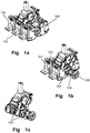
- Figs. 1a, 1b and 1c illustrate schematic views of an overall assembly structure of the moving contact linkage structure of modular circuit breaker according to an embodiment of the present invention.
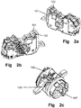
- Figs. 2a, 2b and 2c illustrate schematic views of a single phase contact module within the moving contact linkage structure of modular circuit breaker according to an embodiment of the present invention.
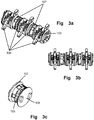
- Figs. 3a, 3b and 3c illustrate schematic views of the connection of linkage members within the moving contact linkage structure of modular circuit breaker according to an embodiment of the present invention.
- Figs. 1 - 3 illustrate a single phase contact module 100.
- the moving contact linkage structure of modular circuit breaker according to the present invention may guarantee reliable linkage of the moving contact and keep consistence of the contact pressure of different contacts.
- moving contact linkage may be realized by assembling the above three types of single phase contact modules in turn, no additional independent linkage element is needed.
- the rotational moving contact of the moving contact linkage structure of modular circuit breaker according to the present invention has a different structure with traditional rotational moving contacts.
- This structure removes the linkage structures independent to the contact module and links the contact modules by directly connection linkage.
- the linkage components are made of insulation materials so as to eliminate the risk of interphase short circuit.
- the present invention also considers the component manufacturability, the installation convenience and structural strength caused by the complexity of the linkage structure of rotational moving contacts.
- the moving contact linkage structure of modular circuit breaker of the present invention supports mass production and has a high reliability.
Landscapes
- Breakers (AREA)
Description
- The present invention relates to a contact module of circuit breaker, and more particularly, relates to a moving contact linkage structure in the operation mechanism of a modular circuit breaker.
- Modularization of contacts is a development trend of molded case circuit breakers. As an important component of the molded case circuit breaker, contact module has drawn great attention. Modern molded case circuit breakers with high breaking capacity generally utilize modularized contacts. The structural styles of the modularized contacts are various. For the purpose of keeping synchronization on the switching of contacts in separate phases, various types of rotational moving contact linkage structures are provided in domestic or foreign products. The rotational moving contact linkage structures may guarantee motion synchronization of contacts of separate phases, and contact balance on bilateral contacts within a rotary dual breakpoint moving contact in a particular single phase. A typical linkage structure is a metal rod member assembled additionally and independently to a contact module. Such a structure has a risk of interphase short circuit. Multiple location fit of the structure may also deteriorate the contact situation of the moving contact, such as unbalanced contact pressure on bilateral contacts of a rotary dual breakpoint moving contact.
- Document
WO 03/050835 A1 - The document
US 2001/048354 A1 relates to a pressure sensitive trip mechanism for a rotary breaker, wherein the circuit breaker operating mechanism is coupled with a center cassette and is connected with the outer cassettes by drive pin. All cassettes along with the circuit breaker operating mechanism are assembled into base and retained therein by the mid-cover. - The document
US 2007/063796 A1 relates to a modular switching device which includes a plurality of interconnected modules, the modules having a control device module and a pole cell module, the modules of the switching device being directly interconnected with a shaft adapted to transfer a torque required for operating the switching device from one module to another module. - The present invention discloses a moving contact linkage structure for modular circuit breaker. The present invention guarantees reliable linkage of the moving contact and uniform contact pressure on separate contacts within the modularized contacts.
- According to the present invention, a moving contact linkage structure for modular circuit breaker is disclosed. The moving contact linkage structure for modular circuit breaker comprises: a first case and a second case, a first shaft, an operation mechanism side plate, an operation mechanism lower connecting rod, a contact rotor, a first linkage member and a second linkage member. The first case has a first mounting hole and the second case has a second mounting hole, the position of the first mounting hole and the position of the second mounting hole correspond to each other. The operation mechanism side plate has a third through hole, the third through hole is positioned at a rotation center of a contact rotor. The operation mechanism lower connecting rod has a fourth through hole, the first shaft connects to the fourth through hole. The contact rotor is rotatable around a rotation center, the contact rotor has mating surfaces on both sides. The first linkage member connects to the mating surface on a first side of the contact rotor. The second linkage member connects to the mating surface on a second side of the contact rotor. The contact rotor, the first linkage member and the second linkage member are mounted in the first mounting hole and the second mounting hole.
- According to an embodiment, the contact rotor has first recess holes. The first recess holes are positioned on the mating surfaces on both sides of the contact rotor. The first recess holes on the mating surface of a same side are symmetric along the rotation center of the contact rotor.
- According to the invention, the first linkage member has a first linkage matching surface and a second linkage matching surface. The first linkage matching surface has a convex first axle at a position corresponding to the rotation center of the contact rotor. The first axle connects to the third through hole. The axial length of the first axle ensures that the first axle can at least go through the third through hole and extend to a first non-through hole on the second linkage member. The first linkage matching surface has a second non-through hole. The second non-through hole is parallel to the rotation axis of the contact rotor, the first shaft connects to the second non-through hole. The second linkage matching surface has second lugs. The second lugs engage with the first recess holes on the contact rotor.
- According to an embodiment, the second linkage member has a third linkage matching surface and a fourth linkage matching surface. The third linkage matching surface has first non-through hole at a position corresponding to the rotation center of the contact rotor, the first non-through hole connects to the first axle of the first linkage member. The third linkage matching surface has a third non-through hole, the third non-through hole is parallel to the rotation axis of the contact rotor, the first shaft connects to the third non-through hole. The third linkage matching surface has second recess holes. The fourth linkage matching surface has third lugs, the third lugs engage with the first recess holes on the contact rotor.
- According to an embodiment, the first linkage member has a first arc surface on the outer circumference. The first arc surface rotates collaboratively with the first case and the second case. The second linkage member has a second arc surface on the outer circumference. The second arc surface rotates collaboratively with the first case and the second case.
- According to an embodiment, the first linkage member has first lugs on the first linkage matching surface. The first lugs engage with the second recess holes on the third linkage matching surface of the second linkage member.
- According to an embodiment, the first case has a fourth lug within the first mounting hole approximate to the outer surface. The fourth lug has a full circle shape. The fourth lug limits the protruding position of the first linkage member or the second linkage member projecting from the outer surface of the first case. The first mounting hole rotates collaboratively with the first arc surface of the first linkage member or the second arc surface of the second linkage member. The first mounting hole does not block the connection between the first lug of the first linkage member and the second recess hole of the second linkage member, nor the connection between first shaft and the first linkage member or the second linkage member.
- According to an embodiment, the second case has a fifth lug within the second mounting hole approximate to the outer surface. The fifth lug has a full circle shape. The fifth lug limits the protruding position of the first linkage member or the second linkage member projecting from the outer surface of the second case. The second mounting hole rotates collaboratively with the first arc surface of the first linkage member or the second arc surface of the second linkage member. The second mounting hole does not block the connection between the first lug of the first linkage member and the second recess hole of the second linkage member, nor the connection between first shaft and the first linkage member or the second linkage member.
- According to an embodiment, the second lugs on the first linkage member and the third lugs on the second linkage member connect to the first recess holes on the mating surfaces on both sides of the contact rotor, the axis of the second non-through hole on the first linkage member and the axis of the third non-through hole on the second linkage member align with each other. The first linkage member, the contact rotor and the second linkage member are disposed in the first mounting hole on the first case and the second mounting hole on the second case, the first case and the second case are assembled to form a single phase contact module.
- According to an embodiment, the third lugs on two second linkage members engage with the first recess holes on the mating surfaces on both sides of the contact rotor. The axes of the third non-through holes on the two second linkage members align with each other. The first linkage member, the contact rotor and the second linkage member are disposed in the first mounting hole on the first case and the second mounting hole on the second case. The first case and the second case are assembled to form a single phase contact module.
- The rotational moving contact of the moving contact linkage structure of modular circuit breaker according to the present invention has a different structure with traditional rotational moving contacts. This structure removes the linkage structures independent to the contact module and links the contact modules by directly connection linkage. The linkage components are made of insulation materials so as to eliminate the risk of interphase short circuit. The present invention also considers the component manufacturability, the installation convenience and structural strength caused by the complexity of the linkage structure of rotational moving contacts. The moving contact linkage structure of modular circuit breaker of the present invention supports mass production and has a high reliability.
- The above and other features, natures, and advantages of the invention will be apparent by the following description of the embodiments incorporating the drawings, wherein:
-
Figs. 1a, 1b and 1c illustrate schematic views of an overall assembly structure of the moving contact linkage structure for modular circuit breaker according to an embodiment of the present invention. -
Figs. 2a, 2b and 2c illustrate schematic views of a single phase contact module within the moving contact linkage structure of modular circuit breaker according to an embodiment of the present invention. -
Figs. 3a, 3b and 3c illustrate schematic views of the engagement for linkage members within the moving contact linkage structure of modular circuit breaker according to an embodiment of the present invention. -
Fig. 4 illustrates a schematic view of a contact rotor within the moving contact linkage structure of modular circuit breaker according to an embodiment of the present invention. -
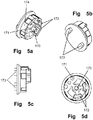
Figs. 5a, 5b, 5c and 5d illustrate schematic views of a first linkage member within the moving contact linkage structure of modular circuit breaker according to an embodiment of the present invention. -
Figs. 6a, 6b, 6c and 6d illustrate schematic views of a second linkage member within the moving contact linkage structure of modular circuit breaker according to an embodiment of the present invention. -
Figs. 7a, 7b and 7c illustrates schematic views of the first case and the second case within the moving contact linkage structure of modular circuit breaker according to an embodiment of the present invention. -
Figs. 8a and 8b illustrate schematic views of an operation mechanism side plate and an operation mechanism lower connecting rod within the moving contact linkage structure of modular circuit breaker according to an embodiment of the present invention. - The present invention provides a moving contact linkage structure of modular circuit breaker. As shown in
Figs.1 - Fig.8 , an embodiment of the moving contact linkage structure of modular circuit breaker is illustrated. The moving contact linkage structure of modular circuit breaker comprises: afirst case 101 and asecond case 102, afirst shaft 103, an operationmechanism side plate 104, an operation mechanism lower connectingrod 105, acontact rotor 106, afirst linkage member 107 and asecond linkage member 108. - The
first case 101 has a first mountinghole 110 and thesecond case 102 has asecond mounting hole 120. The position of the first mountinghole 110 and the position of thesecond mounting hole 120 correspond to each other. The operationmechanism side plate 104 has a third throughhole 140. The third throughhole 140 is positioned at a rotation center of acontact rotor 106. The operation mechanism lower connectingrod 105 has a fourth through hole. Thefirst shaft 103 connects to the fourth through hole by inserting into the fourth through hole. Thecontact rotor 106 is rotatable around a rotation center. Thecontact rotor 106 has mating surfaces on both sides. Thefirst linkage member 107 connects to the mating surface on a first side of thecontact rotor 106. Thesecond linkage member 108 connects to the mating surface on a second side of thecontact rotor 106. Thecontact rotor 106, thefirst linkage member 107 and thesecond linkage member 108 are mounted in the first mountinghole 110 and thesecond mounting hole 120. - As shown in
Fig. 4 , thecontact rotor 106 is rotatable around a rotation center. Thecontact rotor 106 has mating surfaces on both sides. Thecontact rotor 106 has first recess holes 160. The first recess holes 160 are positioned on the mating surfaces on both sides of thecontact rotor 106. The first recess holes 160 on the mating surface of a same side are symmetric along the rotation center of thecontact rotor 106. According to the embodiment shown inFig. 4 , on the mating surface of the same side of thecontact rotor 106, there are at least two first recess holes 160 disposed on each side of the rotation center. Recess hole is utilized in thecontact rotor 106 according to the embodiment shown inFig. 4 . It should be noticed that other forms, such as a lug may be used as well. If lugs are used on thecontact rotor 106, the lugs now utilized on thefirst linkage member 107 and thesecond linkage member 108 shall be replaced with recess grooves correspondingly, so that thecontact rotor 106 may still engage with thefirst linkage member 107 and thesecond linkage member 108. Returning to the embodiment illustrated by the drawings, there are two first recess holes 160 on the mating surface of a same side. The two first recess holes 160 are disposed to be symmetric along the rotation center if there is enough room. The depth of therecess hole 160 is at least 1.5mm, so as to ensure a contact surface enough for bearing the pressure. - As shown in
Figs. 5a, 5b, 5c and 5d , thefirst linkage member 107 has a first linkage matching surface and a second linkage matching surface. The first linkage matching surface has a convexfirst axle 170 at a position corresponding to the rotation center of thecontact rotor 106. Thefirst axle 170 connects to the third throughhole 140 on the operationmechanism side plate 104, the connection is realized by insertion. The axial length of thefirst axle 170 ensures that thefirst axle 170 at least goes through the third throughhole 140 on the operationmechanism side plate 104 and extends to a firstnon-through hole 180 on thesecond linkage member 108. The first linkage matching surface of thefirst linkage member 107 also has a secondnon-through hole 171. The secondnon-through hole 171 is parallel to the rotation axis of the contact rotor. Thefirst shaft 103 connects to the secondnon-through hole 171 by insertion. Thefirst linkage member 107 has at least twofirst lugs 172 on the first linkage matching surface, thefirst lugs 172 engage with second recess holes 182 disposed on thesecond linkage member 108. Thefirst linkage member 107 has at least twosecond lugs 173 on the second linkage matching surface. The second lugs 173 engage with the first recess holes 160 on thecontact rotor 106. Thefirst linkage member 107 has afirst arc surface 174 on the outer circumference. Thefirst arc surface 174 rotates collaboratively with thefirst case 101 and thesecond case 102. - As shown in
Figs. 6a, 6b, 6c and 6d , thesecond linkage member 108 has a third linkage matching surface and a fourth linkage matching surface. The third linkage matching surface of thesecond linkage member 108 has firstnon-through hole 180 at a position corresponding to the rotation center of thecontact rotor 106. The firstnon-through hole 180 connects to thefirst axle 170 of thefirst linkage member 107. The third linkage matching surface of thesecond linkage member 108 has a thirdnon-through hole 181. The thirdnon-through hole 181 is parallel to the rotation axis of thecontact rotor 106. Thefirst shaft 103 connects to the thirdnon-through hole 181 by insertion. The third linkage matching surface of thesecond linkage member 108 has at least two second recess holes 182. The second recess holes 182 engage with thefirst lugs 172 on thefirst linkage member 107. The fourth linkage matching surface of thesecond linkage member 108 has at least twothird lugs 183, thethird lugs 183 engage with the first recess holes 160 on thecontact rotor 106. Thesecond linkage member 108 has asecond arc surface 184 on the outer circumference. Thesecond arc surface 184 rotates collaboratively with thefirst case 101 and thesecond case 102. - As shown in
Figs. 7a, 7b and 7c , thefirst case 101 and thesecond case 102 are the housing of the contact module. Thefirst case 101 has a first mountinghole 110 on a flat surface in the middle part. Thefirst mounting hole 110 accommodates thecontact rotor 106, thefirst linkage member 107 and thesecond linkage member 108. Afourth lug 111 is disposed within the first mountinghole 110 at a position approximate to the outer surface of thefirst case 101. Thefourth lug 111 has a full circle shape. Thefirst linkage 107 or thesecond linkage member 108 may insert into the first mountinghole 110 from the inner surface of thefirst case 101, but thefirst linkage member 107 or thesecond linkage member 108 will not completely project out of the outer surface of thefirst case 101 because of the obstruction of thefourth lug 111. The protruding positions of thefirst linkage member 107 or thesecond linkage member 108 out of the outer surface of thefirst case 101 are limited to their linkage matching surfaces. Thefourth lug 111 limits the protruding position of thefirst linkage member 107 or thesecond linkage member 108 projecting from the outer surface of the first case. Thefirst mounting hole 110 cooperates for rotation with thefirst arc surface 174 of thefirst linkage member 107 or thesecond arc surface 184 of thesecond linkage member 108. Thefirst mounting hole 110 does not block the connection between thefirst lug 172 of thefirst linkage member 107 and thesecond recess hole 182 of thesecond linkage member 108. Thefirst mounting hole 110 does not block the connection betweenfirst shaft 103 and thefirst linkage member 107, or the connection betweenfirst shaft 103 and thesecond linkage member 108. - Still refer to
Figs. 7a, 7b and 7c , thesecond case 102 has asecond mounting hole 120 on a flat surface in the middle part, thesecond mounting hole 120 also accommodates thecontact rotor 106, thefirst linkage member 107 and thesecond linkage member 108. Afifth lug 121 is disposed within thesecond mounting hole 120 at a position approximate to the outer surface of thesecond case 102. Thefifth lug 121 has a full circle shape. Thefirst linkage 107 or thesecond linkage member 108 may insert into thesecond mounting hole 120 from the inner surface of thesecond case 102, but thefirst linkage member 107 or thesecond linkage member 108 will not completely project out of the outer surface of thesecond case 102 because of the obstruction of thefifth lug 121. The protruding positions of thefirst linkage member 107 or thesecond linkage member 108 out of the outer surface of thesecond case 102 are limited to their linkage matching surfaces. Thefifth lug 121 limits the protruding position of thefirst linkage member 107 or thesecond linkage member 108 projecting from the outer surface of the second case. Thesecond mounting hole 120 rotates collaboratively with thefirst arc surface 174 of thefirst linkage member 107 or thesecond arc surface 184 of thesecond linkage member 108. Thesecond mounting hole 120 does not block the connection between thefirst lug 172 of thefirst linkage member 107 and thesecond recess hole 182 of thesecond linkage member 108. Thesecond mounting hole 110 does not block the connection betweenfirst shaft 103 and thefirst linkage member 107, or the connection betweenfirst shaft 103 and thesecond linkage member 108. - As shown in
Figs. 8a and 8b , the operationmechanism side plate 104 has a third throughhole 140 on a flat surface. The third throughhole 140 is positioned at a rotation center of acontact rotor 106. The third throughhole 140 connects with thefirst axle 170 of thefirst linkage member 107 by insertion. The operation mechanism lower connectingrod 105 has a fourth through hole on a flat surface. Thefirst shaft 103 connects to the fourth through hole by insertion. -
Figs. 1a, 1b and 1c illustrate schematic views of an overall assembly structure of the moving contact linkage structure of modular circuit breaker according to an embodiment of the present invention.Figs. 2a, 2b and 2c illustrate schematic views of a single phase contact module within the moving contact linkage structure of modular circuit breaker according to an embodiment of the present invention.Figs. 3a, 3b and 3c illustrate schematic views of the connection of linkage members within the moving contact linkage structure of modular circuit breaker according to an embodiment of the present invention.Figs. 1 - 3 illustrate a singlephase contact module 100. - During the procedure of the engagement:
- 1) The second lugs 173 on the
first linkage member 107 and thethird lugs 183 on thesecond linkage member 108 are inserted and assembled in the recess holes 160 on the mating surfaces on both sides of thecontact rotor 106. The axis of the secondnon-through hole 171 on thefirst linkage member 107 and the axis of the thirdnon-through hole 181 on thesecond linkage member 108 align with each other. Thefirst linkage member 107, thecontact rotor 106 and thesecond linkage member 108 are disposed in the first mountinghole 110 on thefirst case 101 and thesecond mounting hole 120 on thesecond case 102. Thefirst case 101 and thesecond case 102 are assembled to form a first single phase contact module. - 2) Counterchange the assembly position of the
first linkage member 107 and thesecond linkage member 108, that is, counterchange the assembly position of thefirst linkage member 107 and thesecond linkage member 108 for connecting to thecontact rotor 106, to form a second single phase contact module. The second single phase contact module and the first single phase contact module are symmetric with respect to structure. - 3) The third lugs 183 on two
second linkage members 108 are inserted and assembled in the recess holes 160 on the mating surfaces on both sides of thecontact rotor 106. The axes of the two thirdnon-through holes 181 on the twosecond linkage members 108 align with each other. Thecontact rotor 106 and the twosecond linkage members 108 are disposed in the first mountinghole 110 on thefirst case 101 and thesecond mounting hole 120 on thesecond case 102. Thefirst case 101 and thesecond case 102 are assembled to form a third single phase contact module. - The moving contact linkage structure of modular circuit breaker according to the present invention may guarantee reliable linkage of the moving contact and keep consistence of the contact pressure of different contacts. According to the embodiments of the present invention, moving contact linkage may be realized by assembling the above three types of single phase contact modules in turn, no additional independent linkage element is needed.
- The rotational moving contact of the moving contact linkage structure of modular circuit breaker according to the present invention has a different structure with traditional rotational moving contacts. This structure removes the linkage structures independent to the contact module and links the contact modules by directly connection linkage. The linkage components are made of insulation materials so as to eliminate the risk of interphase short circuit. The present invention also considers the component manufacturability, the installation convenience and structural strength caused by the complexity of the linkage structure of rotational moving contacts. The moving contact linkage structure of modular circuit breaker of the present invention supports mass production and has a high reliability.
Claims (10)
- A moving contact linkage structure for modular circuit breaker, comprising:a first case (101) or and a second case (102), the first case (101) or having a first mounting hole (110) and the second case (102) having a second mounting hole (120), a the position of the first mounting hole (110) and the position of the second mounting hole (120) corresponding to each other;a first shaft (103);an operation mechanism side plate (104), the operation mechanism side plate (104) having a third through hole (140), the third through hole (140) being positioned at a rotation center of a contact rotor (106);an operation mechanism lower connecting rod (105), the operation mechanism lower connecting rod (105) having a fourth through hole, the first shaft (103) connecting to the fourth through hole;a contact rotor (106), the contact rotor (106) being rotatable around a rotation center, the contact rotor having mating surfaces on both sides;a first linkage member (107), the first linkage member (107) connecting to the mating surface on a first side of the contact rotor (106), the first linkage member (107) having a convex first axle (170) at a position corresponding to the rotation center of the contact rotor (106), the convex first axle (170) connecting to the third through hole (140);a second linkage member (108), the second linkage member (108) connecting to the mating surface on a second side of the contact rotor (106);wherein the first linkage member (107), the contact rotor (106) and the second linkage member (108) are disposed in the first mounting hole (110) on the first case (101) and the second mounting hole (120) on the second case (102), the first case (101) and the second case (102) are assembled to form a single phase contact module (100);the contact rotor (106) and two second linkage members (108) are disposed in the first mounting hole (110) on the first case (101) and the second mounting hole (120) on the second case (102), the first case (101) and the second case (102) are assembled to form a further single phase contact module (100); andthe single phase contact modules (100) are adapted to be linked by directly connection linkage without any linkage structures independent to the contact modules (100).
- The moving contact linkage structure for modular circuit breaker according to claim 1, characterized in that,
the contact rotor has first recess holes, the first recess holes being positioned on the mating surfaces on both sides of the contact rotor, the first recess holes on the mating surface of a same side being symmetrical along the rotation center of the contact rotor. - The moving contact linkage structure for modular circuit breaker according to claim 2, characterized in that,
the first linkage member has a first linkage matching surface and a second linkage matching surface;
the convex first axle is on the first linkage matching surface at a position corresponding to the rotation center of the contact rotor, the axial length of the first axle ensures the first axle to at least go through the third through hole and extend to a first non-through hole on the second linkage member; the first linkage matching surface has a second non-through hole, the second non-through hole is parallel to the rotation axis of the contact rotor, the first shaft connects to the second non-through hole;
the second linkage matching surface has second lugs, the second lugs engage with the first recess holes on the contact rotor. - The moving contact linkage structure for modular circuit breaker according to claim 3, characterized in that,
the second linkage member has a third linkage matching surface and a fourth linkage matching surface;
the third linkage matching surface has a first non-through hole at a position corresponding to the rotation center of the contact rotor, the first non-through hole connects to the first axle of the first linkage member; the third linkage matching surface has a third non-through hole, the third non-through hole is parallel to the rotation axis of the contact rotor, the first shaft connects to the third non-through hole; the third linkage matching surface has second recess holes;
the fourth linkage matching surface has third lugs, the third lugs engage with the first recess holes on the contact rotor. - The moving contact linkage structure for modular circuit breaker according to claim 4, characterized in that,
the first linkage member has a first arc surface on the outer circumference, when the contact rotor rotates, the first arc surface collaborates with the first case and the second case;
the second linkage member has a second arc surface on the outer circumference, when the contact rotor rotates, the second arc surface collaborates with the first case and the second case. - The moving contact linkage structure for modular circuit breaker according to claim 5, characterized in that,
the first linkage member has first lugs on the first linkage matching surface, the second linkage member having second recess holes on the third linkage matching surface, the first lugs engaging with the second recess holes. - The moving contact linkage structure for modular circuit breaker according to claim 6, characterized in that,
the first case has a fourth lug within the first mounting hole adjacent to the outer surface, the fourth lug has a full circle shape, the fourth lug limits the protruding position of the first linkage member or the second linkage member projecting from the outer surface of the first case;
when the contact rotor rotates, the first mounting hole collaborates with the first arc surface of the first linkage member or the second arc surface of the second linkage member;
the first mounting hole does not block the connection between the first lug of the first linkage member and the second recess hole of the second linkage member, nor the connection between the first shaft and the first linkage member or the second linkage member. - The moving contact linkage structure for modular circuit breaker according to claim 6, characterized in that,
the second case has a fifth lug within the second mounting hole adjacent to the outer surface, the fifth lug has a full circle shape, the fifth lug limits the protruding position of the first linkage member or the second linkage member projecting from the outer surface of the second case;
when the contact rotor rotates, the second mounting hole collaborates with the first arc surface of the first linkage member or the second arc surface of the second linkage member;
the second mounting hole does not block the connection between the first lug of the first linkage member and the second recess hole of the second linkage member, nor the connection between the first shaft and the first linkage member or the second linkage member. - The moving contact linkage structure for modular circuit breaker according to claim 7 or 8, characterized in that,
the second lugs on the first linkage member and the third lugs on the second linkage member connect to the first recess holes on the mating surfaces on both sides of the contact rotor, the axis of the second non-through hole on the first linkage member and the axis of the third non-through hole on the second linkage member align with each other;
the first linkage member, the contact rotor and the second linkage member are disposed in the first mounting hole on the first case and the second mounting hole on the second case, the first case and the second case are assembled to form a single phase contact module. - The moving contact linkage structure for modular circuit breaker according to claim 7 or 8, characterized in that,
the third lugs on two second linkage members respectively engage with the first recess holes on the mating surfaces on both sides of the contact rotor;
the axes of the two third non-through holes on the two second linkage members align with each other;
the contact rotor and the two second linkage members are disposed in the first mounting hole on the first case and the second mounting hole on the second case, the first case and the second case are assembled to form a single phase contact module.
Applications Claiming Priority (2)
| Application Number | Priority Date | Filing Date | Title |
|---|---|---|---|
| CN201110287701.4A CN103021745B (en) | 2011-09-26 | 2011-09-26 | Moving contact linkage structure of modularized circuit breaker |
| PCT/CN2012/081803 WO2013044765A1 (en) | 2011-09-26 | 2012-09-24 | A linkage structure of the moving contact of the modular circuit breaker |
Publications (3)
| Publication Number | Publication Date |
|---|---|
| EP2763154A1 EP2763154A1 (en) | 2014-08-06 |
| EP2763154A4 EP2763154A4 (en) | 2015-08-12 |
| EP2763154B1 true EP2763154B1 (en) | 2017-03-29 |
Family
ID=47970233
Family Applications (1)
| Application Number | Title | Priority Date | Filing Date |
|---|---|---|---|
| EP12834733.3A Active EP2763154B1 (en) | 2011-09-26 | 2012-09-24 | A linkage structure of the moving contact of the modular circuit breaker |
Country Status (6)
| Country | Link |
|---|---|
| EP (1) | EP2763154B1 (en) |
| CN (1) | CN103021745B (en) |
| BR (1) | BR112014007148B1 (en) |
| ES (1) | ES2622654T3 (en) |
| MY (1) | MY175371A (en) |
| WO (1) | WO2013044765A1 (en) |
Families Citing this family (4)
| Publication number | Priority date | Publication date | Assignee | Title |
|---|---|---|---|---|
| CN104362055B (en) * | 2014-12-02 | 2016-06-15 | 南京大全电气研究院有限公司 | A kind of modular single-breakpoint circuit breaker contact system |
| CN104733257B (en) * | 2015-03-23 | 2017-01-25 | 厦门宏发开关设备有限公司 | A Quickly Assembled Switch Circuit Breaker |
| CN107170651B (en) * | 2016-03-07 | 2019-09-06 | 浙江正泰电器股份有限公司 | The turning gear of breaker |
| CN108648936B (en) * | 2018-07-13 | 2024-05-14 | 上海良信电器股份有限公司 | Connection structure of low-voltage switch moving contact and operating mechanism |
Citations (1)
| Publication number | Priority date | Publication date | Assignee | Title |
|---|---|---|---|---|
| US20010048354A1 (en) * | 2000-05-16 | 2001-12-06 | Gary Douville | Pressure sensitive trip mechanism for a rotary breaker |
Family Cites Families (12)
| Publication number | Priority date | Publication date | Assignee | Title |
|---|---|---|---|---|
| US6480082B1 (en) * | 1996-12-25 | 2002-11-12 | Hitachi, Ltd. | Circuit breaker |
| DE19910032C1 (en) * | 1999-03-08 | 2000-04-06 | Moeller Gmbh | Multiple pole switch for power switching, has chamber housing containing adjacent switch chambers with common switch shaft, in which each chamber has interacting fixed, pivotable contacts |
| ES2249875T3 (en) * | 1999-11-03 | 2006-04-01 | AEG NIEDERSPANNUNGSTECHNIK GMBH & CO. KG | ROTARY CONTACT ARM ARRANGEMENT FOR SWITCH. |
| ITMI20012587A1 (en) * | 2001-12-10 | 2003-06-10 | Abb Service Srl | CONTACT SHAFT FOR A LOW VOLTAGE POWER SWITCH |
| ITMI20012586A1 (en) * | 2001-12-10 | 2003-06-10 | Abb Service Srl | ELECTRIC POLE FOR A LOW VOLTAGE POWER SWITCH, AND RELATED SWITCH |
| US6791440B2 (en) * | 2002-08-02 | 2004-09-14 | General Electric Company | Apparatus for electrically isolating circuit breaker rotor components |
| FI116864B (en) * | 2004-01-19 | 2006-03-15 | Abb Oy | Modular switchgear |
| KR100574788B1 (en) * | 2004-10-07 | 2006-04-27 | 엘에스산전 주식회사 | Contact assembly of circuit breaker |
| CN2845154Y (en) * | 2005-12-07 | 2006-12-06 | 上海电器科学研究所(集团)有限公司 | The link gear of breaker of plastic casing |
| CN201417722Y (en) * | 2009-06-11 | 2010-03-03 | 常熟开关制造有限公司(原常熟开关厂) | Double-break moulded case circuit breaker with improved structure |
| US9129768B2 (en) * | 2009-10-15 | 2015-09-08 | Siemens Aktiengesellschaft | Multipole electrical switching device |
| CN201804806U (en) * | 2010-07-30 | 2011-04-20 | 上海良信电器股份有限公司 | Plastic casing type circuit breaker with rotating shaft linkage system |
-
2011
- 2011-09-26 CN CN201110287701.4A patent/CN103021745B/en active Active
-
2012
- 2012-09-24 EP EP12834733.3A patent/EP2763154B1/en active Active
- 2012-09-24 WO PCT/CN2012/081803 patent/WO2013044765A1/en not_active Ceased
- 2012-09-24 MY MYPI2014000888A patent/MY175371A/en unknown
- 2012-09-24 BR BR112014007148-9A patent/BR112014007148B1/en active IP Right Grant
- 2012-09-24 ES ES12834733.3T patent/ES2622654T3/en active Active
Patent Citations (1)
| Publication number | Priority date | Publication date | Assignee | Title |
|---|---|---|---|---|
| US20010048354A1 (en) * | 2000-05-16 | 2001-12-06 | Gary Douville | Pressure sensitive trip mechanism for a rotary breaker |
Also Published As
| Publication number | Publication date |
|---|---|
| BR112014007148B1 (en) | 2021-03-02 |
| EP2763154A4 (en) | 2015-08-12 |
| WO2013044765A1 (en) | 2013-04-04 |
| EP2763154A1 (en) | 2014-08-06 |
| BR112014007148A2 (en) | 2017-04-04 |
| CN103021745A (en) | 2013-04-03 |
| MY175371A (en) | 2020-06-23 |
| CN103021745B (en) | 2015-03-25 |
| ES2622654T3 (en) | 2017-07-06 |
Similar Documents
| Publication | Publication Date | Title |
|---|---|---|
| CN101635231B (en) | Molded case circuit breaker | |
| CN204375671U (en) | Multi-pole double-break | |
| EP2009658B1 (en) | Circuit breaker subassembly | |
| US6259338B1 (en) | Multipole circuit breaker | |
| EP1454331B1 (en) | Contact supporting shaft for a low-voltage power circuit breaker | |
| EP1883944B1 (en) | Switch adaptable to different operating configurations and improved axial support | |
| RU2699389C2 (en) | Actuator of automatic circuit breaker | |
| US9129768B2 (en) | Multipole electrical switching device | |
| EP2763154A1 (en) | A linkage structure of the moving contact of the modular circuit breaker | |
| US7683281B2 (en) | Circuit breaker with suspended mobile contact assembly | |
| CN101176176B (en) | Circuit breakers with interchangeable operating mechanisms and suspended moving contact assemblies | |
| KR20170117826A (en) | Disconnect switch for gas insulated switchgear | |
| CN119028778A (en) | Auxiliary switches and frame circuit breakers | |
| CN201576641U (en) | Contact supporting bar of low-voltage electric breaker | |
| CN116631821A (en) | Contact rotating mechanism and circuit breaker | |
| JP2010027465A (en) | Operation device of switch |
Legal Events
| Date | Code | Title | Description |
|---|---|---|---|
| PUAI | Public reference made under article 153(3) epc to a published international application that has entered the european phase |
Free format text: ORIGINAL CODE: 0009012 |
|
| 17P | Request for examination filed |
Effective date: 20140423 |
|
| AK | Designated contracting states |
Kind code of ref document: A1 Designated state(s): AL AT BE BG CH CY CZ DE DK EE ES FI FR GB GR HR HU IE IS IT LI LT LU LV MC MK MT NL NO PL PT RO RS SE SI SK SM TR |
|
| DAX | Request for extension of the european patent (deleted) | ||
| RA4 | Supplementary search report drawn up and despatched (corrected) |
Effective date: 20150714 |
|
| RIC1 | Information provided on ipc code assigned before grant |
Ipc: H01H 1/20 20060101ALI20150708BHEP Ipc: H01H 9/00 20060101ALN20150708BHEP Ipc: H01H 71/10 20060101AFI20150708BHEP |
|
| 17Q | First examination report despatched |
Effective date: 20160506 |
|
| GRAP | Despatch of communication of intention to grant a patent |
Free format text: ORIGINAL CODE: EPIDOSNIGR1 |
|
| RIC1 | Information provided on ipc code assigned before grant |
Ipc: H01H 1/20 20060101ALI20160930BHEP Ipc: H01H 71/10 20060101AFI20160930BHEP Ipc: H01H 9/00 20060101ALN20160930BHEP |
|
| RIC1 | Information provided on ipc code assigned before grant |
Ipc: H01H 9/00 20060101ALN20161012BHEP Ipc: H01H 71/10 20060101AFI20161012BHEP Ipc: H01H 1/20 20060101ALI20161012BHEP |
|
| INTG | Intention to grant announced |
Effective date: 20161028 |
|
| GRAS | Grant fee paid |
Free format text: ORIGINAL CODE: EPIDOSNIGR3 |
|
| GRAA | (expected) grant |
Free format text: ORIGINAL CODE: 0009210 |
|
| AK | Designated contracting states |
Kind code of ref document: B1 Designated state(s): AL AT BE BG CH CY CZ DE DK EE ES FI FR GB GR HR HU IE IS IT LI LT LU LV MC MK MT NL NO PL PT RO RS SE SI SK SM TR |
|
| REG | Reference to a national code |
Ref country code: GB Ref legal event code: FG4D |
|
| REG | Reference to a national code |
Ref country code: CH Ref legal event code: EP |
|
| REG | Reference to a national code |
Ref country code: AT Ref legal event code: REF Ref document number: 880468 Country of ref document: AT Kind code of ref document: T Effective date: 20170415 |
|
| REG | Reference to a national code |
Ref country code: IE Ref legal event code: FG4D |
|
| REG | Reference to a national code |
Ref country code: DE Ref legal event code: R096 Ref document number: 602012030575 Country of ref document: DE |
|
| REG | Reference to a national code |
Ref country code: ES Ref legal event code: FG2A Ref document number: 2622654 Country of ref document: ES Kind code of ref document: T3 Effective date: 20170706 |
|
| PG25 | Lapsed in a contracting state [announced via postgrant information from national office to epo] |
Ref country code: HR Free format text: LAPSE BECAUSE OF FAILURE TO SUBMIT A TRANSLATION OF THE DESCRIPTION OR TO PAY THE FEE WITHIN THE PRESCRIBED TIME-LIMIT Effective date: 20170329 Ref country code: LT Free format text: LAPSE BECAUSE OF FAILURE TO SUBMIT A TRANSLATION OF THE DESCRIPTION OR TO PAY THE FEE WITHIN THE PRESCRIBED TIME-LIMIT Effective date: 20170329 Ref country code: NO Free format text: LAPSE BECAUSE OF FAILURE TO SUBMIT A TRANSLATION OF THE DESCRIPTION OR TO PAY THE FEE WITHIN THE PRESCRIBED TIME-LIMIT Effective date: 20170629 Ref country code: GR Free format text: LAPSE BECAUSE OF FAILURE TO SUBMIT A TRANSLATION OF THE DESCRIPTION OR TO PAY THE FEE WITHIN THE PRESCRIBED TIME-LIMIT Effective date: 20170630 Ref country code: FI Free format text: LAPSE BECAUSE OF FAILURE TO SUBMIT A TRANSLATION OF THE DESCRIPTION OR TO PAY THE FEE WITHIN THE PRESCRIBED TIME-LIMIT Effective date: 20170329 |
|
| REG | Reference to a national code |
Ref country code: NL Ref legal event code: MP Effective date: 20170329 |
|
| REG | Reference to a national code |
Ref country code: AT Ref legal event code: MK05 Ref document number: 880468 Country of ref document: AT Kind code of ref document: T Effective date: 20170329 |
|
| PG25 | Lapsed in a contracting state [announced via postgrant information from national office to epo] |
Ref country code: RS Free format text: LAPSE BECAUSE OF FAILURE TO SUBMIT A TRANSLATION OF THE DESCRIPTION OR TO PAY THE FEE WITHIN THE PRESCRIBED TIME-LIMIT Effective date: 20170329 Ref country code: LV Free format text: LAPSE BECAUSE OF FAILURE TO SUBMIT A TRANSLATION OF THE DESCRIPTION OR TO PAY THE FEE WITHIN THE PRESCRIBED TIME-LIMIT Effective date: 20170329 Ref country code: BG Free format text: LAPSE BECAUSE OF FAILURE TO SUBMIT A TRANSLATION OF THE DESCRIPTION OR TO PAY THE FEE WITHIN THE PRESCRIBED TIME-LIMIT Effective date: 20170629 Ref country code: SE Free format text: LAPSE BECAUSE OF FAILURE TO SUBMIT A TRANSLATION OF THE DESCRIPTION OR TO PAY THE FEE WITHIN THE PRESCRIBED TIME-LIMIT Effective date: 20170329 |
|
| PG25 | Lapsed in a contracting state [announced via postgrant information from national office to epo] |
Ref country code: NL Free format text: LAPSE BECAUSE OF FAILURE TO SUBMIT A TRANSLATION OF THE DESCRIPTION OR TO PAY THE FEE WITHIN THE PRESCRIBED TIME-LIMIT Effective date: 20170329 |
|
| PG25 | Lapsed in a contracting state [announced via postgrant information from national office to epo] |
Ref country code: CZ Free format text: LAPSE BECAUSE OF FAILURE TO SUBMIT A TRANSLATION OF THE DESCRIPTION OR TO PAY THE FEE WITHIN THE PRESCRIBED TIME-LIMIT Effective date: 20170329 Ref country code: RO Free format text: LAPSE BECAUSE OF FAILURE TO SUBMIT A TRANSLATION OF THE DESCRIPTION OR TO PAY THE FEE WITHIN THE PRESCRIBED TIME-LIMIT Effective date: 20170329 Ref country code: IT Free format text: LAPSE BECAUSE OF FAILURE TO SUBMIT A TRANSLATION OF THE DESCRIPTION OR TO PAY THE FEE WITHIN THE PRESCRIBED TIME-LIMIT Effective date: 20170329 Ref country code: EE Free format text: LAPSE BECAUSE OF FAILURE TO SUBMIT A TRANSLATION OF THE DESCRIPTION OR TO PAY THE FEE WITHIN THE PRESCRIBED TIME-LIMIT Effective date: 20170329 Ref country code: SK Free format text: LAPSE BECAUSE OF FAILURE TO SUBMIT A TRANSLATION OF THE DESCRIPTION OR TO PAY THE FEE WITHIN THE PRESCRIBED TIME-LIMIT Effective date: 20170329 Ref country code: AT Free format text: LAPSE BECAUSE OF FAILURE TO SUBMIT A TRANSLATION OF THE DESCRIPTION OR TO PAY THE FEE WITHIN THE PRESCRIBED TIME-LIMIT Effective date: 20170329 |
|
| PG25 | Lapsed in a contracting state [announced via postgrant information from national office to epo] |
Ref country code: IS Free format text: LAPSE BECAUSE OF FAILURE TO SUBMIT A TRANSLATION OF THE DESCRIPTION OR TO PAY THE FEE WITHIN THE PRESCRIBED TIME-LIMIT Effective date: 20170729 Ref country code: PT Free format text: LAPSE BECAUSE OF FAILURE TO SUBMIT A TRANSLATION OF THE DESCRIPTION OR TO PAY THE FEE WITHIN THE PRESCRIBED TIME-LIMIT Effective date: 20170731 Ref country code: PL Free format text: LAPSE BECAUSE OF FAILURE TO SUBMIT A TRANSLATION OF THE DESCRIPTION OR TO PAY THE FEE WITHIN THE PRESCRIBED TIME-LIMIT Effective date: 20170329 Ref country code: SM Free format text: LAPSE BECAUSE OF FAILURE TO SUBMIT A TRANSLATION OF THE DESCRIPTION OR TO PAY THE FEE WITHIN THE PRESCRIBED TIME-LIMIT Effective date: 20170329 |
|
| REG | Reference to a national code |
Ref country code: DE Ref legal event code: R097 Ref document number: 602012030575 Country of ref document: DE |
|
| PG25 | Lapsed in a contracting state [announced via postgrant information from national office to epo] |
Ref country code: DK Free format text: LAPSE BECAUSE OF FAILURE TO SUBMIT A TRANSLATION OF THE DESCRIPTION OR TO PAY THE FEE WITHIN THE PRESCRIBED TIME-LIMIT Effective date: 20170329 |
|
| PLBE | No opposition filed within time limit |
Free format text: ORIGINAL CODE: 0009261 |
|
| STAA | Information on the status of an ep patent application or granted ep patent |
Free format text: STATUS: NO OPPOSITION FILED WITHIN TIME LIMIT |
|
| 26N | No opposition filed |
Effective date: 20180103 |
|
| REG | Reference to a national code |
Ref country code: DE Ref legal event code: R119 Ref document number: 602012030575 Country of ref document: DE |
|
| REG | Reference to a national code |
Ref country code: CH Ref legal event code: PL |
|
| PG25 | Lapsed in a contracting state [announced via postgrant information from national office to epo] |
Ref country code: MC Free format text: LAPSE BECAUSE OF FAILURE TO SUBMIT A TRANSLATION OF THE DESCRIPTION OR TO PAY THE FEE WITHIN THE PRESCRIBED TIME-LIMIT Effective date: 20170329 Ref country code: SI Free format text: LAPSE BECAUSE OF FAILURE TO SUBMIT A TRANSLATION OF THE DESCRIPTION OR TO PAY THE FEE WITHIN THE PRESCRIBED TIME-LIMIT Effective date: 20170329 |
|
| REG | Reference to a national code |
Ref country code: IE Ref legal event code: MM4A |
|
| REG | Reference to a national code |
Ref country code: BE Ref legal event code: MM Effective date: 20170930 |
|
| PG25 | Lapsed in a contracting state [announced via postgrant information from national office to epo] |
Ref country code: LU Free format text: LAPSE BECAUSE OF NON-PAYMENT OF DUE FEES Effective date: 20170924 |
|
| REG | Reference to a national code |
Ref country code: FR Ref legal event code: ST Effective date: 20180531 |
|
| PG25 | Lapsed in a contracting state [announced via postgrant information from national office to epo] |
Ref country code: DE Free format text: LAPSE BECAUSE OF NON-PAYMENT OF DUE FEES Effective date: 20180404 Ref country code: CH Free format text: LAPSE BECAUSE OF NON-PAYMENT OF DUE FEES Effective date: 20170930 Ref country code: LI Free format text: LAPSE BECAUSE OF NON-PAYMENT OF DUE FEES Effective date: 20170930 Ref country code: IE Free format text: LAPSE BECAUSE OF NON-PAYMENT OF DUE FEES Effective date: 20170924 |
|
| PG25 | Lapsed in a contracting state [announced via postgrant information from national office to epo] |
Ref country code: FR Free format text: LAPSE BECAUSE OF NON-PAYMENT OF DUE FEES Effective date: 20171002 Ref country code: BE Free format text: LAPSE BECAUSE OF NON-PAYMENT OF DUE FEES Effective date: 20170930 |
|
| PG25 | Lapsed in a contracting state [announced via postgrant information from national office to epo] |
Ref country code: MT Free format text: LAPSE BECAUSE OF NON-PAYMENT OF DUE FEES Effective date: 20170924 |
|
| PG25 | Lapsed in a contracting state [announced via postgrant information from national office to epo] |
Ref country code: HU Free format text: LAPSE BECAUSE OF FAILURE TO SUBMIT A TRANSLATION OF THE DESCRIPTION OR TO PAY THE FEE WITHIN THE PRESCRIBED TIME-LIMIT; INVALID AB INITIO Effective date: 20120924 |
|
| PG25 | Lapsed in a contracting state [announced via postgrant information from national office to epo] |
Ref country code: CY Free format text: LAPSE BECAUSE OF NON-PAYMENT OF DUE FEES Effective date: 20170329 |
|
| PG25 | Lapsed in a contracting state [announced via postgrant information from national office to epo] |
Ref country code: MK Free format text: LAPSE BECAUSE OF FAILURE TO SUBMIT A TRANSLATION OF THE DESCRIPTION OR TO PAY THE FEE WITHIN THE PRESCRIBED TIME-LIMIT Effective date: 20170329 |
|
| PG25 | Lapsed in a contracting state [announced via postgrant information from national office to epo] |
Ref country code: AL Free format text: LAPSE BECAUSE OF FAILURE TO SUBMIT A TRANSLATION OF THE DESCRIPTION OR TO PAY THE FEE WITHIN THE PRESCRIBED TIME-LIMIT Effective date: 20170329 |
|
| PGFP | Annual fee paid to national office [announced via postgrant information from national office to epo] |
Ref country code: TR Payment date: 20250917 Year of fee payment: 14 |
|
| PGFP | Annual fee paid to national office [announced via postgrant information from national office to epo] |
Ref country code: GB Payment date: 20250821 Year of fee payment: 14 |
|
| PGFP | Annual fee paid to national office [announced via postgrant information from national office to epo] |
Ref country code: ES Payment date: 20251014 Year of fee payment: 14 |