EP2762996A2 - Display apparatus and method of displaying image using the same - Google Patents
Display apparatus and method of displaying image using the same Download PDFInfo
- Publication number
- EP2762996A2 EP2762996A2 EP13186096.7A EP13186096A EP2762996A2 EP 2762996 A2 EP2762996 A2 EP 2762996A2 EP 13186096 A EP13186096 A EP 13186096A EP 2762996 A2 EP2762996 A2 EP 2762996A2
- Authority
- EP
- European Patent Office
- Prior art keywords
- tapping
- display
- image
- signal
- peripheral portion
- Prior art date
- Legal status (The legal status is an assumption and is not a legal conclusion. Google has not performed a legal analysis and makes no representation as to the accuracy of the status listed.)
- Withdrawn
Links
Images




Classifications
-
- G—PHYSICS
- G06—COMPUTING OR CALCULATING; COUNTING
- G06F—ELECTRIC DIGITAL DATA PROCESSING
- G06F3/00—Input arrangements for transferring data to be processed into a form capable of being handled by the computer; Output arrangements for transferring data from processing unit to output unit, e.g. interface arrangements
- G06F3/01—Input arrangements or combined input and output arrangements for interaction between user and computer
- G06F3/03—Arrangements for converting the position or the displacement of a member into a coded form
- G06F3/041—Digitisers, e.g. for touch screens or touch pads, characterised by the transducing means
- G06F3/0412—Digitisers structurally integrated in a display
-
- G—PHYSICS
- G06—COMPUTING OR CALCULATING; COUNTING
- G06F—ELECTRIC DIGITAL DATA PROCESSING
- G06F1/00—Details not covered by groups G06F3/00 - G06F13/00 and G06F21/00
- G06F1/16—Constructional details or arrangements
- G06F1/1613—Constructional details or arrangements for portable computers
- G06F1/1626—Constructional details or arrangements for portable computers with a single-body enclosure integrating a flat display, e.g. Personal Digital Assistants [PDAs]
-
- G—PHYSICS
- G02—OPTICS
- G02F—OPTICAL DEVICES OR ARRANGEMENTS FOR THE CONTROL OF LIGHT BY MODIFICATION OF THE OPTICAL PROPERTIES OF THE MEDIA OF THE ELEMENTS INVOLVED THEREIN; NON-LINEAR OPTICS; FREQUENCY-CHANGING OF LIGHT; OPTICAL LOGIC ELEMENTS; OPTICAL ANALOGUE/DIGITAL CONVERTERS
- G02F1/00—Devices or arrangements for the control of the intensity, colour, phase, polarisation or direction of light arriving from an independent light source, e.g. switching, gating or modulating; Non-linear optics
- G02F1/01—Devices or arrangements for the control of the intensity, colour, phase, polarisation or direction of light arriving from an independent light source, e.g. switching, gating or modulating; Non-linear optics for the control of the intensity, phase, polarisation or colour
- G02F1/13—Devices or arrangements for the control of the intensity, colour, phase, polarisation or direction of light arriving from an independent light source, e.g. switching, gating or modulating; Non-linear optics for the control of the intensity, phase, polarisation or colour based on liquid crystals, e.g. single liquid crystal display cells
- G02F1/133—Constructional arrangements; Operation of liquid crystal cells; Circuit arrangements
- G02F1/1333—Constructional arrangements; Manufacturing methods
-
- G—PHYSICS
- G06—COMPUTING OR CALCULATING; COUNTING
- G06F—ELECTRIC DIGITAL DATA PROCESSING
- G06F1/00—Details not covered by groups G06F3/00 - G06F13/00 and G06F21/00
- G06F1/16—Constructional details or arrangements
- G06F1/1613—Constructional details or arrangements for portable computers
- G06F1/1633—Constructional details or arrangements of portable computers not specific to the type of enclosures covered by groups G06F1/1615 - G06F1/1626
- G06F1/1637—Details related to the display arrangement, including those related to the mounting of the display in the housing
-
- G—PHYSICS
- G06—COMPUTING OR CALCULATING; COUNTING
- G06F—ELECTRIC DIGITAL DATA PROCESSING
- G06F1/00—Details not covered by groups G06F3/00 - G06F13/00 and G06F21/00
- G06F1/16—Constructional details or arrangements
- G06F1/1613—Constructional details or arrangements for portable computers
- G06F1/1633—Constructional details or arrangements of portable computers not specific to the type of enclosures covered by groups G06F1/1615 - G06F1/1626
- G06F1/1684—Constructional details or arrangements related to integrated I/O peripherals not covered by groups G06F1/1635 - G06F1/1675
-
- G—PHYSICS
- G06—COMPUTING OR CALCULATING; COUNTING
- G06F—ELECTRIC DIGITAL DATA PROCESSING
- G06F3/00—Input arrangements for transferring data to be processed into a form capable of being handled by the computer; Output arrangements for transferring data from processing unit to output unit, e.g. interface arrangements
- G06F3/01—Input arrangements or combined input and output arrangements for interaction between user and computer
- G06F3/048—Interaction techniques based on graphical user interfaces [GUI]
- G06F3/0484—Interaction techniques based on graphical user interfaces [GUI] for the control of specific functions or operations, e.g. selecting or manipulating an object, an image or a displayed text element, setting a parameter value or selecting a range
- G06F3/0485—Scrolling or panning
-
- G—PHYSICS
- G06—COMPUTING OR CALCULATING; COUNTING
- G06F—ELECTRIC DIGITAL DATA PROCESSING
- G06F3/00—Input arrangements for transferring data to be processed into a form capable of being handled by the computer; Output arrangements for transferring data from processing unit to output unit, e.g. interface arrangements
- G06F3/14—Digital output to display device ; Cooperation and interconnection of the display device with other functional units
- G06F3/147—Digital output to display device ; Cooperation and interconnection of the display device with other functional units using display panels
-
- G—PHYSICS
- G09—EDUCATION; CRYPTOGRAPHY; DISPLAY; ADVERTISING; SEALS
- G09F—DISPLAYING; ADVERTISING; SIGNS; LABELS OR NAME-PLATES; SEALS
- G09F9/00—Indicating arrangements for variable information in which the information is built-up on a support by selection or combination of individual elements
-
- H—ELECTRICITY
- H10—SEMICONDUCTOR DEVICES; ELECTRIC SOLID-STATE DEVICES NOT OTHERWISE PROVIDED FOR
- H10K—ORGANIC ELECTRIC SOLID-STATE DEVICES
- H10K50/00—Organic light-emitting devices
-
- G—PHYSICS
- G06—COMPUTING OR CALCULATING; COUNTING
- G06F—ELECTRIC DIGITAL DATA PROCESSING
- G06F2200/00—Indexing scheme relating to G06F1/04 - G06F1/32
- G06F2200/16—Indexing scheme relating to G06F1/16 - G06F1/18
- G06F2200/163—Indexing scheme relating to constructional details of the computer
- G06F2200/1636—Sensing arrangement for detection of a tap gesture on the housing
Definitions
- Embodiments of the present invention relate generally to a display apparatus and a method of displaying an image. More particularly, embodiments of the present invention relate to a display apparatus capable of sensing a tapping and a method of displaying an image.
- An image such as a character or a picture, provided through a network (e.g., the internet) may be displayed on a smart phone.
- a network e.g., the internet
- a size of the image may be greater than a size of a display part of the smart phone, and thus, a user scrolls several times when the user wants to view the uppermost portion or the lower most portion of the image while viewing the image.
- aspects of the present invention provide a display apparatus capable of easily displaying an end portion of an image, and a method of using the display apparatus.
- a display apparatus includes: a display configured to display an end portion of an image according to a tapping signal; and a tap sensor configured to sense tapping at a peripheral portion of the display and to output the tapping signal to the display when the tapping is sensed.
- the tap sensor may include an upper side tapping sensor configured to sense the tapping at an upper side peripheral portion of the display and to output an upper side signal when the tapping is sensed at the upper side peripheral portion.
- the display may be configured to display an upper side end portion of the image in response to the upper side signal.
- the upper side tapping sensor may include a vibration sensor for sensing the tapping.
- the tap sensor may include a lower side tapping sensor configured to sense the tapping at a lower side peripheral portion of the display and to output a lower side signal when the tapping is sensed at the lower side peripheral portion.
- the display may be configured to display a lower side end portion of the image in response to the lower side signal.
- the lower side tapping sensor may include a vibration sensor for sensing the tapping.
- the tap sensor may include a left side tapping sensor configured to sense the tapping at a left side peripheral portion of the display and to output a left side signal when the tapping is sensed at the left side peripheral portion.
- the display may be configured to display a left side end portion of the image in response to the left side signal.
- the left side tapping sensor may include a vibration sensor for sensing the tapping.
- the tap sensor may include a right side tapping sensor configured to sense the tapping at a right side peripheral portion of the display and to output a right side signal when the tapping is sensed at the right side peripheral portion.
- the display may be configured to display a right side end portion of the image in response to the right side signal.
- the right side tapping sensor may include a vibration sensor for sensing the tapping.
- the tap sensor may be configured to output the tapping signal when the tap sensor senses the tapping including two taps.
- the tap sensor may include a vibration sensor for sensing the tapping.
- the display apparatus may be a liquid crystal display apparatus including a liquid crystal.
- the display apparatus may be an organic light emitting diode display apparatus including an organic light emitting diode.
- the side tapping sensors may comprise the same size. Alternatively, a number of tap sensing parts may have a bigger surface or area, for example to take account for preferred wishes of the user like when for example the upper and/or lower end portion of the image is viewed most.
- the side tapping sensors can be arranged directly adjacent to each other. Further, two side tapping sensors may be activated at the same time for example the upper side tapping sensor and the right side tapping sensor. Accordingly, the signals UPS and RIS are outputted and the upper right corner of the image is displayed according to the two tapping signals.
- a method of displaying an image includes: sensing tapping; outputting a tapping signal when the tapping is sensed; and displaying an end portion of the image on a display according to the tapping signal.
- the tapping may be sensed at a peripheral portion around the display.
- Outputting the tapping signal may include outputting an upper side signal when the tapping is sensed at an upper side peripheral portion of the display.
- Displaying the end portion of the image may include displaying an upper side end portion of the image in response to the upper side signal.
- Outputting the tapping signal may include outputting a lower side signal when the tapping is sensed at a lower side peripheral portion of the display.
- Displaying the end portion of the image may include displaying a lower side end portion of the image in response to the lower side signal.
- Outputting the tapping signal may include outputting a left side signal when the tapping is sensed at a left side peripheral portion of the display.
- Displaying the end portion of the image may include displaying a left side end portion of the image in response to the left side signal.
- Outputting the tapping signal may include outputting a right side signal when the tapping is sensed at a right side peripheral portion of the display.
- Displaying the end portion of the image may include displaying a right side end portion of the image in response to the right side signal.
- Outputting the tapping signal may include outputting the tapping signal when the tapping includes two taps.
- a display apparatus and a method of displaying an image using the display apparatus may sense a tapping of a user applied to an upper side peripheral portion, a lower side peripheral portion, a left side peripheral portion and a right side peripheral portion around a display to output a tapping signal, and the display displays the uppermost portion, the lowest portion, the leftmost portion, and the rightmost portion of an image in response to the tapping signal.
- the user may easily change the view to display the uppermost portion, the lowest portion, the leftmost portion, and the rightmost portion of the image without scrolling (e.g., scrolling several times) when viewing another portion of the image.
- FIG. 1 is a block diagram illustrating a display apparatus according to an example embodiment of the present invention.
- FIGS. 2A, 2B , 2C and 2D are plan views illustrating the display apparatus of FIG. 1 .
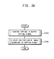
- FIGS. 3A , 3B and 3C are flow charts illustrating a method of displaying an image using the display apparatus in FIGS. 1 , 2A , 2B , 2C and 2D .
- FIG. 1 is a block diagram illustrating a display apparatus according to an example embodiment of the present invention
- FIGS. 2A, 2B , 2C and 2D are plan views illustrating the display apparatus of FIG. 1 .
- the display apparatus 100 includes a display part 110 (or display) and a tap sensing part 130 (or tap sensor).
- the display apparatus 100 may be a liquid crystal display (LCD) apparatus including a liquid crystal.
- the display apparatus 100 may be an organic light emitting diode (OLED) display apparatus including an organic light emitting diode (OLED).
- the display apparatus 100 may be included in a smart phone or a tablet PC.
- the display part 110 displays an image.
- the image includes at least one of a character, a picture, or a moving picture.
- the display part 110 may display a portion of the image.
- a size of the picture may be greater than a size of the display part 110, and in this case, the display part 110 may display the portion of the image.
- the display part 110 displays an end portion of the image according to a tapping signal received from the tap sensing part 130.
- the display part 110 may display the uppermost portion of the image according to (e.g., in response to) the tapping signal when displaying a middle portion of the image.
- the display part 110 may display the lowest portion of the image according to (e.g., in response to) the tapping signal when displaying the middle portion of the image, the display part 110 may display the leftmost portion of the image according to (e.g., in response to) the tapping signal when displaying the middle portion of the image, or the display part 110 may display the rightmost portion of the image according to (e.g., in response to) the tapping signal when displaying the middle portion of the image.
- the tap sensing part 130 includes an upper side tap sensing part 131, a lower side tap sensing part 132, a left side tap sensing part 133, and a right side tap sensing part 134.
- the upper side tap sensing part 131 senses tapping at an upper side peripheral portion 121 at (e.g., disposed at or located at) an upper side of the display part 110. For example, as illustrated in FIG. 2A , when the upper side peripheral portion 121 is tapped by a finger of a user, the upper side tap sensing part 131 senses the tapping and outputs an upper side signal UPS to the display part 110.
- the upper side tap sensing part 131 may output the upper side signal UPS after sensing two taps generated in a suitable time (e.g., a preset or predetermined time) so as to prevent outputting the upper side signal UPS caused by a tapping owing to a mistake of the user (e.g., accidental or unintentional taps).
- the upper side tap sensing part 131 may include a vibration sensor for sensing the tapping.
- the display part 110 displays an upper side end portion of the image in response to the upper side signal UPS outputted from the upper side tap sensing part 131 of the tap sensing part 130.
- the display part 110 displays the uppermost portion of the image in response to the upper side signal UPS.
- the uppermost portion of the image may include a menu, an internet address and so on.
- the user may adjust the view to display the uppermost portion of the image without scrolling (e.g., scrolling several times) when viewing (e.g. initially viewing) another portion (e.g., the middle portion) of the image.
- the lower side tap sensing part 132 senses the tapping at a lower side peripheral portion 122 at (e.g., disposed at or located at) a lower side of the display part 110. For example, as illustrated in FIG. 2B , when the lower side peripheral portion 122 is tapped by the finger of the user, the lower side tap sensing part 132 senses the tapping and outputs a lower side signal LOS to the display part 110.
- the lower side tap sensing part 132 may output the lower side signal LOS after sensing two taps generated in a suitable (e.g., set or predetermined) time so as to prevent outputting the lower side signal LOS caused by a tapping owing to a mistake of the user.
- the lower side tap sensing part 132 may include a vibration sensor for sensing the tapping.
- the display part 110 displays a lower side end portion of the image in response to the lower side signal LOS outputted from the lower side tap sensing part 132 of the tap sensing part 130.
- the display part 110 displays the lowest portion of the image in response to the lower side signal LOS.
- the lowest portion of the image may include a comment, a recommendation button, and so on.
- the user may adjust the view to display the lowest portion of the image without scrolling (e.g. scrolling several times) when viewing (e.g., initially viewing) another portion (e.g., the middle portion) of the image.
- the left side tap sensing part 133 senses the tapping at a left side peripheral portion 123 at (e.g., located at or disposed at) a left side of the display part 110. For example, as illustrated in FIG. 2C , when the left side peripheral portion 123 is tapped by the finger of the user, the left side tap sensing part 133 senses the tapping and outputs a left side signal LES to the display part 110.
- the left side tap sensing part 133 may output the left side signal LES after sensing two taps generated in a suitable (e.g., a set or predetermined) time so as to prevent outputting the left side signal LES caused by a tapping owing to a mistake of the user.
- the left side tap sensing part 133 may include a vibration sensor for sensing the tapping.
- the display part 110 displays a left side end portion of the image in response to the left side signal LES outputted from the left side tap sensing part 133 of the tap sensing part 130.
- the display part 110 displays the leftmost portion of the image in response to the left side signal LES.
- the leftmost portion of the image may display the front most portion of a menu, a picture, or an album of music spread in a horizontal direction.
- the user may adjust the view to display the leftmost portion of the image without scrolling (e.g., scrolling several times) when viewing (e.g. initially viewing) another portion (e.g., the middle portion) of the image.
- the right side tap sensing part 134 senses the tapping at a right side peripheral portion 124 at (e.g., located at or disposed at) a right side of the display part 110. For example, as illustrated in FIG. 2D , when the right side peripheral portion 124 is tapped by the finger of the user, the right side tap sensing part 134 senses the tapping and outputs a right side signal RIS to the display part 110.
- the right side tap sensing part 134 may output the right side signal RIS after sensing two taps generated in a suitable (e.g., a set or predetermined) time so as to prevent outputting the right side signal RIS caused by a tapping owing to a mistake of the user.
- the right side tap sensing part 134 may include a vibration sensor for sensing the tapping.
- the display part 110 displays a right side end portion of the image in response to the right side signal RIS outputted from the right side tap sensing part 134 of the tap sensing part 130.
- the display part 110 displays the rightmost portion of the image in response to the right side signal RIS.
- the rightmost portion of the image may display the rearmost portion of a menu, a picture, or an album of music spread in a horizontal direction.
- the user may change the view to display the rightmost portion of the image without scrolling (e.g., scrolling several times) when viewing (e.g., initially viewing) another portion (e.g., the middle portion) of the image.
- FIGS. 3A , 3B and 3C are flow charts illustrating a method of displaying an image using the display apparatus 100 in FIGS. 1 , 2A , 2B , 2C and 2D .
- the tap sensing part 130 senses the tapping to output the tapping signal (S100).
- the upper side tap sensing part 131 of the tap sensing part 130 determines whether or not the upper side peripheral portion 121 is tapped (S111).
- the tap sensing part 130 outputs the upper side signal UPS (S112).
- the upper side tap sensing part 131 may include the vibration sensor for sensing the tapping, and the upper side tap sensing part 131 may output the upper side signal UPS after sensing the two taps generated in the predetermined time so as to prevent outputting the upper side signal UPS caused by the tapping owing to the mistake of the user.
- the lower side tap sensing part 132 of the tap sensing part 130 determines whether or not the lower side peripheral portion 122 is tapped (S121).
- the tap sensing part 130 outputs the lower side signal LOS (S122).
- the lower side tap sensing part 132 may include the vibration sensor for sensing the tapping, and the lower side tap sensing part 132 may output the lower side signal LOS after sensing the two taps generated in the predetermined time so as to prevent outputting the lower side signal LOS caused by the tapping owing to the mistake of the user.
- the left side tap sensing part 133 of the tap sensing part 130 determines whether or not the left side peripheral portion 123 is tapped (S131).
- the tap sensing part 130 outputs the left side signal LES (S132).
- the left side tap sensing part 133 may include the vibration sensor for sensing the tapping, and the left side tap sensing part 133 may output the left side signal LES after sensing the two taps generated in the predetermined time so as to prevent outputting the left side signal LES caused by the tapping owing to the mistake of the user.
- the right side tap sensing part 134 of the tap sensing part 130 determines whether or not the right side peripheral portion 124 is tapped (S141).
- the tap sensing part 130 outputs the right side signal RIS (S142).
- the right side tap sensing part 134 may include the vibration sensor for sensing the tapping, and the right side tap sensing part 134 may output the right side signal RIS after sensing the two taps generated in the determined time so as to prevent outputting the right side signal RIS caused by the tapping owing to the mistake of the user.
- the display part 110 displays an end portion of the image according to the tapping signal outputted from the tap sensing part 130 (S200).
- the display part 110 determines whether the upper side signal UPS is received from the tap sensing part 130 (S211). When the display part 110 receives the upper side signal UPS from the tap sensing part 130, the display part 110 displays the upper side end portion of the image (S212). For example, the display part 110 displays the uppermost portion of the image in response to the upper side signal UPS.
- the user may easily change the view to display the uppermost portion of the image without scrolling when viewing (e.g., initially viewing) another portion (e.g., the middle portion) of the image.
- the display part 110 determines whether the lower side signal LOS is received from the tap sensing part 130 (S221). When the display part 110 receives the lower side signal LOS from the tap sensing part 130, the display part 110 displays the lower side end portion of the image (S222). For example, the display part 110 displays the lowest portion of the image in response to the lower side signal LOS.
- the user may easily change the view to display the lowest portion of the image without scrolling when viewing (e.g., initially viewing) the middle portion of the image.
- the display part 110 determines whether the left side signal LES is received from the tap sensing part 130 (S231). When the display part 110 receives the left side signal LES from the tap sensing part 130, the display part 110 displays the left side end portion of the image (S232). For example, the display part 110 displays the leftmost portion of the image in response to the left side signal LES.
- the user may easily change the view to display the leftmost portion of the image without scrolling when viewing (e.g., initially viewing) another portion (e.g., the middle portion) of the image.
- the display part 110 determines whether the right side signal RIS is received from the tap sensing part 130 (S241). When the display part 110 receives the right side signal RIS from the tap sensing part 130, the display part 110 displays the right side end portion of the image (S242). For example, the display part 110 displays the rightmost portion of the image in response to the right side signal RIS. Thus, according to one embodiment, the user may simply watch the rightmost portion of the image without the several scrolling during watching the middle portion of the image.
- the tap sensing part 130 senses the tapping of the user applied to the uppers side peripheral portion 121, the lower side peripheral portion 122, the left side peripheral portion 123 and the right side peripheral portion 124 disposed around the display part 110 to output the tapping signal, and the display part 110 displays the uppermost portion, the lowest portion, the leftmost portion and the rightmost portion of the image in response to the tapping signal.
- the user may easily change the view to display the uppermost portion, the lowest portion, the leftmost portion and the rightmost portion without the scrolling when viewing another portion of the image.
- the present inventive concept may be applied to an electric device having a display apparatus.
- the present inventive concept may be applied to a laptop, a digital camera, a cellular phone, a smart phone, a personal digital assistant (PDA), a portable multimedia player (PMP), a navigation system, a video phone, etc.
- PDA personal digital assistant
- PMP portable multimedia player
Landscapes
- Engineering & Computer Science (AREA)
- Theoretical Computer Science (AREA)
- Physics & Mathematics (AREA)
- General Engineering & Computer Science (AREA)
- General Physics & Mathematics (AREA)
- Human Computer Interaction (AREA)
- Computer Hardware Design (AREA)
- Nonlinear Science (AREA)
- Optics & Photonics (AREA)
- Mathematical Physics (AREA)
- Chemical & Material Sciences (AREA)
- Crystallography & Structural Chemistry (AREA)
- Controls And Circuits For Display Device (AREA)
- Testing, Inspecting, Measuring Of Stereoscopic Televisions And Televisions (AREA)
Abstract
Description
- This application claims priority to and the benefit of Korean Patent Applications No.
10-2013-0011912, filed on February 1, 2013 - Embodiments of the present invention relate generally to a display apparatus and a method of displaying an image. More particularly, embodiments of the present invention relate to a display apparatus capable of sensing a tapping and a method of displaying an image.
- An image, such as a character or a picture, provided through a network (e.g., the internet) may be displayed on a smart phone.
- However, a size of the image may be greater than a size of a display part of the smart phone, and thus, a user scrolls several times when the user wants to view the uppermost portion or the lower most portion of the image while viewing the image.
- Aspects of the present invention provide a display apparatus capable of easily displaying an end portion of an image, and a method of using the display apparatus.
- According to one embodiment, a display apparatus includes: a display configured to display an end portion of an image according to a tapping signal; and a tap sensor configured to sense tapping at a peripheral portion of the display and to output the tapping signal to the display when the tapping is sensed.
- The tap sensor may include an upper side tapping sensor configured to sense the tapping at an upper side peripheral portion of the display and to output an upper side signal when the tapping is sensed at the upper side peripheral portion.
- The display may be configured to display an upper side end portion of the image in response to the upper side signal.
- The upper side tapping sensor may include a vibration sensor for sensing the tapping.
- The tap sensor may include a lower side tapping sensor configured to sense the tapping at a lower side peripheral portion of the display and to output a lower side signal when the tapping is sensed at the lower side peripheral portion.
- The display may be configured to display a lower side end portion of the image in response to the lower side signal.
- The lower side tapping sensor may include a vibration sensor for sensing the tapping.
- The tap sensor may include a left side tapping sensor configured to sense the tapping at a left side peripheral portion of the display and to output a left side signal when the tapping is sensed at the left side peripheral portion.
- The display may be configured to display a left side end portion of the image in response to the left side signal.
- The left side tapping sensor may include a vibration sensor for sensing the tapping.
- The tap sensor may include a right side tapping sensor configured to sense the tapping at a right side peripheral portion of the display and to output a right side signal when the tapping is sensed at the right side peripheral portion.
- The display may be configured to display a right side end portion of the image in response to the right side signal.
- The right side tapping sensor may include a vibration sensor for sensing the tapping.
- The tap sensor may be configured to output the tapping signal when the tap sensor senses the tapping including two taps.
- The tap sensor may include a vibration sensor for sensing the tapping.
- The display apparatus may be a liquid crystal display apparatus including a liquid crystal.
- The display apparatus may be an organic light emitting diode display apparatus including an organic light emitting diode.
- The side tapping sensors may comprise the same size. Alternatively, a number of tap sensing parts may have a bigger surface or area, for example to take account for preferred wishes of the user like when for example the upper and/or lower end portion of the image is viewed most. The side tapping sensors can be arranged directly adjacent to each other. Further, two side tapping sensors may be activated at the same time for example the upper side tapping sensor and the right side tapping sensor. Accordingly, the signals UPS and RIS are outputted and the upper right corner of the image is displayed according to the two tapping signals.
- According to one embodiment, a method of displaying an image includes: sensing tapping; outputting a tapping signal when the tapping is sensed; and displaying an end portion of the image on a display according to the tapping signal.
- The tapping may be sensed at a peripheral portion around the display.
- Outputting the tapping signal may include outputting an upper side signal when the tapping is sensed at an upper side peripheral portion of the display.
- Displaying the end portion of the image may include displaying an upper side end portion of the image in response to the upper side signal.
- Outputting the tapping signal may include outputting a lower side signal when the tapping is sensed at a lower side peripheral portion of the display.
- Displaying the end portion of the image may include displaying a lower side end portion of the image in response to the lower side signal.
- Outputting the tapping signal may include outputting a left side signal when the tapping is sensed at a left side peripheral portion of the display.
- Displaying the end portion of the image may include displaying a left side end portion of the image in response to the left side signal.
- Outputting the tapping signal may include outputting a right side signal when the tapping is sensed at a right side peripheral portion of the display.
- Displaying the end portion of the image may include displaying a right side end portion of the image in response to the right side signal.
- Outputting the tapping signal may include outputting the tapping signal when the tapping includes two taps.
- Therefore, a display apparatus and a method of displaying an image using the display apparatus according to example embodiments may sense a tapping of a user applied to an upper side peripheral portion, a lower side peripheral portion, a left side peripheral portion and a right side peripheral portion around a display to output a tapping signal, and the display displays the uppermost portion, the lowest portion, the leftmost portion, and the rightmost portion of an image in response to the tapping signal. Thus, the user may easily change the view to display the uppermost portion, the lowest portion, the leftmost portion, and the rightmost portion of the image without scrolling (e.g., scrolling several times) when viewing another portion of the image.
- Illustrative, non-limiting example embodiments will be more clearly understood from the following detailed description taken in conjunction with the accompanying drawings.
-
FIG. 1 is a block diagram illustrating a display apparatus according to an example embodiment of the present invention. -
FIGS. 2A, 2B ,2C and 2D are plan views illustrating the display apparatus ofFIG. 1 . -
FIGS. 3A ,3B and3C are flow charts illustrating a method of displaying an image using the display apparatus inFIGS. 1 ,2A ,2B ,2C and 2D . - Various example embodiments will be described more fully hereinafter with reference to the accompanying drawings, in which some example embodiments are shown. The present inventive concept may, however, be embodied in many different forms and should not be construed as limited to the example embodiments set forth herein. Rather, these example embodiments are provided so that this disclosure will be thorough and complete, and will fully convey the scope of the present inventive concept to those skilled in the art. In the drawings, the sizes and relative sizes of layers and regions may be exaggerated for clarity. Like numerals refer to like elements throughout.
- It will be understood that, although the terms first, second, third, etc. may be used herein to describe various elements, these elements should not be limited by these terms. These terms are used to distinguish one element from another. Thus, a first element discussed below could be termed a second element without departing from the teachings of the present inventive concept. As used herein, the term "and/or" includes any and all combinations of one or more of the associated listed items.
- It will be understood that when an element is referred to as being "connected" or "coupled" to another element, it can be directly connected or coupled to the other element or one or more intervening elements may be present. In contrast, when an element is referred to as being "directly connected" or "directly coupled" to another element, there are no intervening elements present. Other words used to describe the relationship between elements should be interpreted in a like fashion (e.g., "between" versus "directly between," "adjacent" versus "directly adjacent," etc.).
- The terminology used herein is for the purpose of describing particular example embodiments only and is not intended to be limiting of the present inventive concept. As used herein, the singular forms "a," "an" and "the" are intended to include the plural forms as well, unless the context clearly indicates otherwise. It will be further understood that the terms "includes", "including", "comprises" and/or "comprising," when used in this specification, specify the presence of stated features, integers, steps, operations, elements, and/or components, but do not preclude the presence or addition of one or more other features, integers, steps, operations, elements, components, and/or groups thereof.
- Unless otherwise defined, all terms (including technical and scientific terms) used herein have the same meaning as commonly understood by one of ordinary skill in the art to which this inventive concept belongs. It will be further understood that terms, such as those defined in commonly used dictionaries, should be interpreted as having a meaning that is consistent with their meaning in the context of the relevant art and will not be interpreted in an idealized or overly formal sense unless expressly so defined herein.
-
FIG. 1 is a block diagram illustrating a display apparatus according to an example embodiment of the present invention, andFIGS. 2A, 2B ,2C and 2D are plan views illustrating the display apparatus ofFIG. 1 . - Referring to
FIGS. 1 ,2A ,2B ,2C and 2D , thedisplay apparatus 100 includes a display part 110 (or display) and a tap sensing part 130 (or tap sensor). Thedisplay apparatus 100 may be a liquid crystal display (LCD) apparatus including a liquid crystal. Alternatively, thedisplay apparatus 100 may be an organic light emitting diode (OLED) display apparatus including an organic light emitting diode (OLED). For example, thedisplay apparatus 100 may be included in a smart phone or a tablet PC. - The
display part 110 displays an image. The image includes at least one of a character, a picture, or a moving picture. When thedisplay apparatus 100 is included in a smart phone or a tablet PC, thedisplay part 110 may display a portion of the image. For example, a size of the picture may be greater than a size of thedisplay part 110, and in this case, thedisplay part 110 may display the portion of the image. - The
display part 110 displays an end portion of the image according to a tapping signal received from thetap sensing part 130. For example, thedisplay part 110 may display the uppermost portion of the image according to (e.g., in response to) the tapping signal when displaying a middle portion of the image. In addition, thedisplay part 110 may display the lowest portion of the image according to (e.g., in response to) the tapping signal when displaying the middle portion of the image, thedisplay part 110 may display the leftmost portion of the image according to (e.g., in response to) the tapping signal when displaying the middle portion of the image, or thedisplay part 110 may display the rightmost portion of the image according to (e.g., in response to) the tapping signal when displaying the middle portion of the image. - The
tap sensing part 130, according to the present embodiment, includes an upper sidetap sensing part 131, a lower sidetap sensing part 132, a left sidetap sensing part 133, and a right sidetap sensing part 134. - The upper side
tap sensing part 131 senses tapping at an upper sideperipheral portion 121 at (e.g., disposed at or located at) an upper side of thedisplay part 110. For example, as illustrated inFIG. 2A , when the upper sideperipheral portion 121 is tapped by a finger of a user, the upper sidetap sensing part 131 senses the tapping and outputs an upper side signal UPS to thedisplay part 110. The upper sidetap sensing part 131 may output the upper side signal UPS after sensing two taps generated in a suitable time (e.g., a preset or predetermined time) so as to prevent outputting the upper side signal UPS caused by a tapping owing to a mistake of the user (e.g., accidental or unintentional taps). According to one embodiment, the upper sidetap sensing part 131 may include a vibration sensor for sensing the tapping. - The
display part 110 displays an upper side end portion of the image in response to the upper side signal UPS outputted from the upper sidetap sensing part 131 of thetap sensing part 130. For example, thedisplay part 110 displays the uppermost portion of the image in response to the upper side signal UPS. The uppermost portion of the image may include a menu, an internet address and so on. According to an aspect of the inventive concept, the user may adjust the view to display the uppermost portion of the image without scrolling (e.g., scrolling several times) when viewing (e.g. initially viewing) another portion (e.g., the middle portion) of the image. - The lower side
tap sensing part 132 senses the tapping at a lower sideperipheral portion 122 at (e.g., disposed at or located at) a lower side of thedisplay part 110. For example, as illustrated inFIG. 2B , when the lower sideperipheral portion 122 is tapped by the finger of the user, the lower sidetap sensing part 132 senses the tapping and outputs a lower side signal LOS to thedisplay part 110. The lower sidetap sensing part 132 may output the lower side signal LOS after sensing two taps generated in a suitable (e.g., set or predetermined) time so as to prevent outputting the lower side signal LOS caused by a tapping owing to a mistake of the user. According to one embodiment, the lower sidetap sensing part 132 may include a vibration sensor for sensing the tapping. - The
display part 110 displays a lower side end portion of the image in response to the lower side signal LOS outputted from the lower sidetap sensing part 132 of thetap sensing part 130. For example, thedisplay part 110 displays the lowest portion of the image in response to the lower side signal LOS. The lowest portion of the image may include a comment, a recommendation button, and so on. According to an aspect of the inventive concept, the user may adjust the view to display the lowest portion of the image without scrolling (e.g. scrolling several times) when viewing (e.g., initially viewing) another portion (e.g., the middle portion) of the image. - The left side
tap sensing part 133 senses the tapping at a left sideperipheral portion 123 at (e.g., located at or disposed at) a left side of thedisplay part 110. For example, as illustrated inFIG. 2C , when the left sideperipheral portion 123 is tapped by the finger of the user, the left sidetap sensing part 133 senses the tapping and outputs a left side signal LES to thedisplay part 110. The left sidetap sensing part 133 may output the left side signal LES after sensing two taps generated in a suitable (e.g., a set or predetermined) time so as to prevent outputting the left side signal LES caused by a tapping owing to a mistake of the user. According to one embodiment, the left sidetap sensing part 133 may include a vibration sensor for sensing the tapping. - The
display part 110 displays a left side end portion of the image in response to the left side signal LES outputted from the left sidetap sensing part 133 of thetap sensing part 130. For example, thedisplay part 110 displays the leftmost portion of the image in response to the left side signal LES. The leftmost portion of the image may display the front most portion of a menu, a picture, or an album of music spread in a horizontal direction. According to an aspect of the inventive concept, the user may adjust the view to display the leftmost portion of the image without scrolling (e.g., scrolling several times) when viewing (e.g. initially viewing) another portion (e.g., the middle portion) of the image. - The right side
tap sensing part 134 senses the tapping at a right sideperipheral portion 124 at (e.g., located at or disposed at) a right side of thedisplay part 110. For example, as illustrated inFIG. 2D , when the right sideperipheral portion 124 is tapped by the finger of the user, the right sidetap sensing part 134 senses the tapping and outputs a right side signal RIS to thedisplay part 110. The right sidetap sensing part 134 may output the right side signal RIS after sensing two taps generated in a suitable (e.g., a set or predetermined) time so as to prevent outputting the right side signal RIS caused by a tapping owing to a mistake of the user. According to one embodiment, the right sidetap sensing part 134 may include a vibration sensor for sensing the tapping. - The
display part 110 displays a right side end portion of the image in response to the right side signal RIS outputted from the right sidetap sensing part 134 of thetap sensing part 130. For example, thedisplay part 110 displays the rightmost portion of the image in response to the right side signal RIS. The rightmost portion of the image may display the rearmost portion of a menu, a picture, or an album of music spread in a horizontal direction. According to an aspect of the inventive concept, the user may change the view to display the rightmost portion of the image without scrolling (e.g., scrolling several times) when viewing (e.g., initially viewing) another portion (e.g., the middle portion) of the image. -
FIGS. 3A ,3B and3C are flow charts illustrating a method of displaying an image using thedisplay apparatus 100 inFIGS. 1 ,2A ,2B ,2C and 2D . - Referring to
FIGS. 1 ,2A ,2B ,2C ,2D ,3A ,3B and3C , thetap sensing part 130 senses the tapping to output the tapping signal (S100). - For example, when the upper side
peripheral portion 121 is tapped by the finger of the user, the upper sidetap sensing part 131 of thetap sensing part 130 determines whether or not the upper sideperipheral portion 121 is tapped (S111). When the upper sidetap sensing part 131 determines that the upper sideperipheral portion 121 is tapped, thetap sensing part 130 outputs the upper side signal UPS (S112). The upper sidetap sensing part 131 may include the vibration sensor for sensing the tapping, and the upper sidetap sensing part 131 may output the upper side signal UPS after sensing the two taps generated in the predetermined time so as to prevent outputting the upper side signal UPS caused by the tapping owing to the mistake of the user. - In addition, when the lower side
peripheral portion 122 is tapped by the finger of the user, the lower sidetap sensing part 132 of thetap sensing part 130 determines whether or not the lower sideperipheral portion 122 is tapped (S121). When the lower sidetap sensing part 132 determines that the lower sideperipheral portion 122 is tapped, thetap sensing part 130 outputs the lower side signal LOS (S122). The lower sidetap sensing part 132 may include the vibration sensor for sensing the tapping, and the lower sidetap sensing part 132 may output the lower side signal LOS after sensing the two taps generated in the predetermined time so as to prevent outputting the lower side signal LOS caused by the tapping owing to the mistake of the user. - In addition, when the left side
peripheral portion 123 is tapped by the finger of the user, the left sidetap sensing part 133 of thetap sensing part 130 determines whether or not the left sideperipheral portion 123 is tapped (S131). When the left sidetap sensing part 133 determines that the left sideperipheral portion 123 is tapped, thetap sensing part 130 outputs the left side signal LES (S132). The left sidetap sensing part 133 may include the vibration sensor for sensing the tapping, and the left sidetap sensing part 133 may output the left side signal LES after sensing the two taps generated in the predetermined time so as to prevent outputting the left side signal LES caused by the tapping owing to the mistake of the user. - In addition, when the right side
peripheral portion 124 is tapped by the finger of the user, the right sidetap sensing part 134 of thetap sensing part 130 determines whether or not the right sideperipheral portion 124 is tapped (S141). When the right sidetap sensing part 134 determines that the right sideperipheral portion 124 is tapped, thetap sensing part 130 outputs the right side signal RIS (S142). The right sidetap sensing part 134 may include the vibration sensor for sensing the tapping, and the right sidetap sensing part 134 may output the right side signal RIS after sensing the two taps generated in the determined time so as to prevent outputting the right side signal RIS caused by the tapping owing to the mistake of the user. - The
display part 110 displays an end portion of the image according to the tapping signal outputted from the tap sensing part 130 (S200). - For example, the
display part 110 determines whether the upper side signal UPS is received from the tap sensing part 130 (S211). When thedisplay part 110 receives the upper side signal UPS from thetap sensing part 130, thedisplay part 110 displays the upper side end portion of the image (S212). For example, thedisplay part 110 displays the uppermost portion of the image in response to the upper side signal UPS. Thus, according to one embodiment, the user may easily change the view to display the uppermost portion of the image without scrolling when viewing (e.g., initially viewing) another portion (e.g., the middle portion) of the image. - In addition, the
display part 110 determines whether the lower side signal LOS is received from the tap sensing part 130 (S221). When thedisplay part 110 receives the lower side signal LOS from thetap sensing part 130, thedisplay part 110 displays the lower side end portion of the image (S222). For example, thedisplay part 110 displays the lowest portion of the image in response to the lower side signal LOS. Thus, according to one embodiment, the user may easily change the view to display the lowest portion of the image without scrolling when viewing (e.g., initially viewing) the middle portion of the image. - In addition, the
display part 110 determines whether the left side signal LES is received from the tap sensing part 130 (S231). When thedisplay part 110 receives the left side signal LES from thetap sensing part 130, thedisplay part 110 displays the left side end portion of the image (S232). For example, thedisplay part 110 displays the leftmost portion of the image in response to the left side signal LES. Thus, according to one embodiment, the user may easily change the view to display the leftmost portion of the image without scrolling when viewing (e.g., initially viewing) another portion (e.g., the middle portion) of the image. - In addition, the
display part 110 determines whether the right side signal RIS is received from the tap sensing part 130 (S241). When thedisplay part 110 receives the right side signal RIS from thetap sensing part 130, thedisplay part 110 displays the right side end portion of the image (S242). For example, thedisplay part 110 displays the rightmost portion of the image in response to the right side signal RIS. Thus, according to one embodiment, the user may simply watch the rightmost portion of the image without the several scrolling during watching the middle portion of the image. - According to the present example embodiments, the
tap sensing part 130 senses the tapping of the user applied to the uppers sideperipheral portion 121, the lower sideperipheral portion 122, the left sideperipheral portion 123 and the right sideperipheral portion 124 disposed around thedisplay part 110 to output the tapping signal, and thedisplay part 110 displays the uppermost portion, the lowest portion, the leftmost portion and the rightmost portion of the image in response to the tapping signal. Thus, the user may easily change the view to display the uppermost portion, the lowest portion, the leftmost portion and the rightmost portion without the scrolling when viewing another portion of the image. - The present inventive concept may be applied to an electric device having a display apparatus. For example, the present inventive concept may be applied to a laptop, a digital camera, a cellular phone, a smart phone, a personal digital assistant (PDA), a portable multimedia player (PMP), a navigation system, a video phone, etc.
- The foregoing is illustrative of example embodiments and is not to be construed as limiting thereof. Although a few example embodiments have been described, those skilled in the art will readily appreciate that many modifications are possible in the example embodiments without materially departing from the features and aspects of the present inventive concept. Accordingly, all such modifications are intended to be included within the scope of the present inventive concept as defined in the claims.
Claims (11)
- A display apparatus (100) comprising:a display (110) configured to display an end portion of an image according to a tapping signal; anda tap sensor (130) configured to sense tapping at a peripheral portion (121, 122, 123, 124) of the display (110) and to output the tapping signal to the display (110) when the tapping is sensed.
- The display apparatus of claim 1, wherein the tap sensor (130) comprises an upper side tapping sensor (131) configured to sense the tapping at an upper side peripheral portion (121) of the display (110) and to output an upper side signal when the tapping is sensed at the upper side peripheral portion (121), a lower side tapping sensor (132) configured to sense the tapping at a lower side peripheral portion (122) of the display (110) and to output a lower side signal when the tapping is sensed at the lower side peripheral portion (122), a left side tapping sensor (133) configured to sense the tapping at a left side peripheral portion (123) of the display (110) and to output a left side signal when the tapping is sensed at the left side peripheral portion (123) and/or a right side tapping sensor (134) configured to sense the tapping at a right side peripheral portion (124) of the display (110) and to output a right side signal when the tapping is sensed at the right side peripheral portion (124).
- The display apparatus of claim 2, wherein the display (110) is configured to display an upper side end portion of the image in response to the upper side signal, is configured to display a lower side end portion of the image in response to the lower side signal, is configured to display a left side end portion of the image in response to the left side signal and is configured to display a right side end portion of the image in response to the right side signal.
- The display apparatus of one of the preceeding claims, wherein the tap sensor (130) comprises a vibration sensor for sensing the tapping, wherein the upper side tapping sensor (131) comprises a vibration sensor for sensing the tapping, wherein the lower side tapping sensor (132) comprises a vibration sensor for sensing the tapping, wherein the left side tapping sensor (133) comprises a vibration sensor for sensing the tapping and/or wherein the right side tapping sensor (134) comprises a vibration sensor for sensing the tapping.
- The display apparatus of one of the preceeding claims, wherein the tap sensor (130) is configured to output the tapping signal when the tap sensor (130) senses the tapping comprising two taps.
- The display apparatus of one of the preceeding claims, wherein the display apparatus is a liquid crystal display apparatus comprising a liquid crystal and/or wherein the display apparatus is an organic light emitting diode display apparatus comprising an organic light emitting diode.
- A method of displaying an image, the method comprising:sensing tapping (S100, S111, S121, S131, S141);outputting a tapping signal when the tapping is sensed (S112, S122, S132, S142, S141); anddisplaying an end portion of the image on a display according to the tapping signal (S200, S212, S222, S232, S242).
- The method of claim 7, wherein the tapping is sensed at a peripheral portion (121, 122, 123, 124) around the display (110).
- The method of claim 7 or 8, wherein outputting the tapping signal comprises outputting an upper side signal (S112) when the tapping is sensed at an upper side peripheral portion (121) of the display (110), outputting a lower side signal (S122) when the tapping is sensed at a lower side peripheral portion (122) of the display (110), outputting a left side signal (S132) when the tapping is sensed at a left side peripheral portion (123) of the display (110), and/or outputting a right side signal (S142) when the tapping is sensed at a right side peripheral portion (124) of the display (110).
- The method of one of the preceeding claims, wherein displaying the end portion of the image (S200) comprises displaying an upper side end portion of the image in response to the upper side signal (S212), displaying a lower side end portion of the image in response to the lower side signal (S222), displaying a left side end portion of the image in response to the left side signal (S232) and/or displaying a right side end portion of the image in response to the right side signal (S242).
- The method of one of the preceeding claims, wherein outputting the tapping signal (S112, S122, S132, S142, S141) comprises outputting the tapping signal when the tapping comprises two taps.
Applications Claiming Priority (1)
| Application Number | Priority Date | Filing Date | Title |
|---|---|---|---|
| KR1020130011912A KR20140099093A (en) | 2013-02-01 | 2013-02-01 | Display apparatus and method of displaying image using the same |
Publications (2)
| Publication Number | Publication Date |
|---|---|
| EP2762996A2 true EP2762996A2 (en) | 2014-08-06 |
| EP2762996A3 EP2762996A3 (en) | 2016-07-06 |
Family
ID=49304679
Family Applications (1)
| Application Number | Title | Priority Date | Filing Date |
|---|---|---|---|
| EP13186096.7A Withdrawn EP2762996A3 (en) | 2013-02-01 | 2013-09-26 | Display apparatus and method of displaying image using the same |
Country Status (4)
| Country | Link |
|---|---|
| US (1) | US20140218312A1 (en) |
| EP (1) | EP2762996A3 (en) |
| KR (1) | KR20140099093A (en) |
| CN (1) | CN103973839A (en) |
Families Citing this family (2)
| Publication number | Priority date | Publication date | Assignee | Title |
|---|---|---|---|---|
| US20150286402A1 (en) * | 2014-04-08 | 2015-10-08 | Qualcomm Incorporated | Live non-visual feedback during predictive text keyboard operation |
| KR20160068534A (en) * | 2014-12-05 | 2016-06-15 | 엘지전자 주식회사 | Mobile terminal and method for controlling the same |
Family Cites Families (10)
| Publication number | Priority date | Publication date | Assignee | Title |
|---|---|---|---|---|
| US7800592B2 (en) * | 2005-03-04 | 2010-09-21 | Apple Inc. | Hand held electronic device with multiple touch sensing devices |
| WO2005008444A2 (en) * | 2003-07-14 | 2005-01-27 | Matt Pallakoff | System and method for a portbale multimedia client |
| US20070247434A1 (en) * | 2006-04-19 | 2007-10-25 | Cradick Ryan K | Method, apparatus, and computer program product for entry of data or commands based on tap detection |
| JP2010191892A (en) * | 2009-02-20 | 2010-09-02 | Sony Corp | Information processing apparatus, display control method, and program |
| US8537110B2 (en) * | 2009-07-24 | 2013-09-17 | Empire Technology Development Llc | Virtual device buttons |
| CN102023791A (en) * | 2009-09-18 | 2011-04-20 | 比亚迪股份有限公司 | Scrolling control method for touch control device |
| TW201214242A (en) * | 2010-09-24 | 2012-04-01 | Accupoint Technology Inc Ltd | Object sensing device |
| KR101726607B1 (en) * | 2010-10-19 | 2017-04-13 | 삼성전자주식회사 | Method and apparatus for controlling screen in mobile terminal |
| KR101182076B1 (en) * | 2011-03-31 | 2012-09-11 | 선문대학교 산학협력단 | Apparatus and method of screen scrolling for portable terminals with touch screen |
| US20140152585A1 (en) * | 2012-12-04 | 2014-06-05 | Research In Motion Limited | Scroll jump interface for touchscreen input/output device |
-
2013
- 2013-02-01 KR KR1020130011912A patent/KR20140099093A/en not_active Withdrawn
- 2013-07-03 US US13/935,453 patent/US20140218312A1/en not_active Abandoned
- 2013-09-24 CN CN201310455859.7A patent/CN103973839A/en active Pending
- 2013-09-26 EP EP13186096.7A patent/EP2762996A3/en not_active Withdrawn
Non-Patent Citations (1)
| Title |
|---|
| None |
Also Published As
| Publication number | Publication date |
|---|---|
| EP2762996A3 (en) | 2016-07-06 |
| US20140218312A1 (en) | 2014-08-07 |
| KR20140099093A (en) | 2014-08-11 |
| CN103973839A (en) | 2014-08-06 |
Similar Documents
| Publication | Publication Date | Title |
|---|---|---|
| US9606574B2 (en) | Foldable display device and method for controlling the same | |
| AU2013100572B4 (en) | Smart cover peek | |
| KR101749233B1 (en) | Method for controlling the display of a portable computing device | |
| AU2011101581A4 (en) | Method and apparatus of scrolling a document displayed in a browser window | |
| US8791963B2 (en) | Responding to the receipt of zoom commands | |
| WO2009032803A3 (en) | Graphical user interface for mobile electronic device | |
| US20120014054A1 (en) | Altering the flexibility of a display device | |
| US20140298276A1 (en) | Display control device, display control method, and display control program | |
| US10592188B2 (en) | Content bumping in multi-layer display systems | |
| US20130033524A1 (en) | Method for performing display control in response to eye activities of a user, and associated apparatus | |
| US20160163282A1 (en) | Flexible display panel and operation method thereof | |
| TW200611136A (en) | A device and method for processing information | |
| WO2013003105A4 (en) | Electronic device and method with dual mode rear touch pad | |
| WO2008030779A3 (en) | Portable electronic device for photo management | |
| WO2006009692A3 (en) | Multipurpose navigation keys for an electronic imaging device | |
| US20090066664A1 (en) | Touch screen and display method thereof | |
| US20150278990A1 (en) | Display device providing history information and method for controlling the same | |
| US20190164244A1 (en) | Law enforcement officer review website and mobile application | |
| EP2762996A2 (en) | Display apparatus and method of displaying image using the same | |
| US20150172550A1 (en) | Display tiling for enhanced view modes | |
| US20140195900A1 (en) | Computer readable medium for enhanced display of digital text | |
| US20160171659A1 (en) | Method for controlling the display of a portable computing device | |
| US20170255381A1 (en) | Display device | |
| US20090262143A1 (en) | Method for displaying information, and electronic apparatus and storage medium thereof | |
| KR20170116663A (en) | Image processing method and electronic device supporting the same |
Legal Events
| Date | Code | Title | Description |
|---|---|---|---|
| PUAI | Public reference made under article 153(3) epc to a published international application that has entered the european phase |
Free format text: ORIGINAL CODE: 0009012 |
|
| 17P | Request for examination filed |
Effective date: 20130926 |
|
| AK | Designated contracting states |
Kind code of ref document: A2 Designated state(s): AL AT BE BG CH CY CZ DE DK EE ES FI FR GB GR HR HU IE IS IT LI LT LU LV MC MK MT NL NO PL PT RO RS SE SI SK SM TR |
|
| AX | Request for extension of the european patent |
Extension state: BA ME |
|
| RAP1 | Party data changed (applicant data changed or rights of an application transferred) |
Owner name: SAMSUNG DISPLAY CO., LTD. |
|
| PUAL | Search report despatched |
Free format text: ORIGINAL CODE: 0009013 |
|
| AK | Designated contracting states |
Kind code of ref document: A3 Designated state(s): AL AT BE BG CH CY CZ DE DK EE ES FI FR GB GR HR HU IE IS IT LI LT LU LV MC MK MT NL NO PL PT RO RS SE SI SK SM TR |
|
| AX | Request for extension of the european patent |
Extension state: BA ME |
|
| RIC1 | Information provided on ipc code assigned before grant |
Ipc: G06F 3/0485 20130101AFI20160602BHEP Ipc: G06F 1/16 20060101ALI20160602BHEP |
|
| STAA | Information on the status of an ep patent application or granted ep patent |
Free format text: STATUS: REQUEST FOR EXAMINATION WAS MADE |
|
| R17P | Request for examination filed (corrected) |
Effective date: 20161219 |
|
| RBV | Designated contracting states (corrected) |
Designated state(s): AL AT BE BG CH CY CZ DE DK EE ES FI FR GB GR HR HU IE IS IT LI LT LU LV MC MK MT NL NO PL PT RO RS SE SI SK SM TR |
|
| STAA | Information on the status of an ep patent application or granted ep patent |
Free format text: STATUS: EXAMINATION IS IN PROGRESS |
|
| 17Q | First examination report despatched |
Effective date: 20170828 |
|
| STAA | Information on the status of an ep patent application or granted ep patent |
Free format text: STATUS: THE APPLICATION IS DEEMED TO BE WITHDRAWN |
|
| 18D | Application deemed to be withdrawn |
Effective date: 20180109 |