EP2762940A1 - Lens device, and imaging device fitted with said lens device - Google Patents
Lens device, and imaging device fitted with said lens device Download PDFInfo
- Publication number
- EP2762940A1 EP2762940A1 EP12836700.0A EP12836700A EP2762940A1 EP 2762940 A1 EP2762940 A1 EP 2762940A1 EP 12836700 A EP12836700 A EP 12836700A EP 2762940 A1 EP2762940 A1 EP 2762940A1
- Authority
- EP
- European Patent Office
- Prior art keywords
- ring
- operation ring
- lens
- filter
- gear mechanism
- Prior art date
- Legal status (The legal status is an assumption and is not a legal conclusion. Google has not performed a legal analysis and makes no representation as to the accuracy of the status listed.)
- Granted
Links
- 238000003384 imaging method Methods 0.000 title claims abstract description 66
- 230000007246 mechanism Effects 0.000 claims abstract description 158
- 230000005540 biological transmission Effects 0.000 claims abstract description 70
- 238000002834 transmittance Methods 0.000 claims abstract description 44
- 230000008859 change Effects 0.000 claims description 9
- 238000010586 diagram Methods 0.000 description 20
- 230000003287 optical effect Effects 0.000 description 8
- 230000003247 decreasing effect Effects 0.000 description 5
- ZZUFCTLCJUWOSV-UHFFFAOYSA-N furosemide Chemical compound C1=C(Cl)C(S(=O)(=O)N)=CC(C(O)=O)=C1NCC1=CC=CO1 ZZUFCTLCJUWOSV-UHFFFAOYSA-N 0.000 description 4
- 239000000463 material Substances 0.000 description 3
- 230000008901 benefit Effects 0.000 description 2
- 230000000903 blocking effect Effects 0.000 description 2
- 238000001514 detection method Methods 0.000 description 2
- 230000000694 effects Effects 0.000 description 2
- 229920002595 Dielectric elastomer Polymers 0.000 description 1
- 239000003086 colorant Substances 0.000 description 1
- 238000004519 manufacturing process Methods 0.000 description 1
- 230000009467 reduction Effects 0.000 description 1
- 230000004044 response Effects 0.000 description 1
- 230000004304 visual acuity Effects 0.000 description 1
Images





Classifications
-
- G—PHYSICS
- G02—OPTICS
- G02B—OPTICAL ELEMENTS, SYSTEMS OR APPARATUS
- G02B26/00—Optical devices or arrangements for the control of light using movable or deformable optical elements
- G02B26/02—Optical devices or arrangements for the control of light using movable or deformable optical elements for controlling the intensity of light
- G02B26/023—Optical devices or arrangements for the control of light using movable or deformable optical elements for controlling the intensity of light comprising movable attenuating elements, e.g. neutral density filters
-
- G—PHYSICS
- G02—OPTICS
- G02B—OPTICAL ELEMENTS, SYSTEMS OR APPARATUS
- G02B7/00—Mountings, adjusting means, or light-tight connections, for optical elements
- G02B7/02—Mountings, adjusting means, or light-tight connections, for optical elements for lenses
- G02B7/04—Mountings, adjusting means, or light-tight connections, for optical elements for lenses with mechanism for focusing or varying magnification
- G02B7/10—Mountings, adjusting means, or light-tight connections, for optical elements for lenses with mechanism for focusing or varying magnification by relative axial movement of several lenses, e.g. of varifocal objective lens
-
- G—PHYSICS
- G02—OPTICS
- G02B—OPTICAL ELEMENTS, SYSTEMS OR APPARATUS
- G02B5/00—Optical elements other than lenses
- G02B5/005—Diaphragms
-
- G—PHYSICS
- G02—OPTICS
- G02B—OPTICAL ELEMENTS, SYSTEMS OR APPARATUS
- G02B7/00—Mountings, adjusting means, or light-tight connections, for optical elements
- G02B7/02—Mountings, adjusting means, or light-tight connections, for optical elements for lenses
- G02B7/04—Mountings, adjusting means, or light-tight connections, for optical elements for lenses with mechanism for focusing or varying magnification
- G02B7/06—Focusing binocular pairs
Definitions
- the present invention relates to a lens device mounted on a video camera or a television camera.
- the present invention relates to a lens device, which has both of an operation tool that manually operates an aperture stop device so as to adjust an amount of incident light and an operation tool that manually adjusts an amount of transmitted light of a variable light transmission filter, and an imaging device mounted with the lens device.
- an aperture stop (iris) device As the device that adjusts the amount of incident light, an aperture stop (iris) device is generally used.
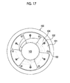
- an aperture stop device 100 shown in Fig. 17 is configured such that a plurality of (six, in the example shown in the drawing) aperture stop blades 101, which functions as an iris, is disposed on a circumference and a driving point 102 of each blade 101 is moved in a direction of an arrow 104 centered on a supporting point 103 so as to decrease an aperture area (aperture size) of a center hole 105 which transmits incident light.
- the center hole 105 is narrowed.
- small aperture blurring may occur, and may deteriorate a quality of a photographed image.
- the ND filter is formed as a discoid filter in which a density of a dimming material continuously changes along the circumference.
- the rotation position of the discoid filter the amount of transmitted light of the filter is controlled.
- JP2006-126504A a light amount adjustment device disclosed in JP2006-126504A has been proposed.
- the light amount adjustment device electrodes are provided on both surfaces of a discoid dielectric elastomer placed on the optical path, a voltage applied between the electrodes is adjusted, and a thickness of the discoid film is controlled, thereby realizing the ND filter of which the amount of transmitted light is variable.
- variable light transmission filter exemplified in JP2007-243928A and JP2006-126504A into the aperture stop device shown in for example Fig. 17 .
- the variable light transmission filter it is difficult to perform imaging that blurs the background through adjustment of the depth of field performed by adjusting the aperture stop diameter, the adjustment being regarded as an advantage of the aperture stop device.
- both the aperture stop device and the variable light transmission filter are able to adjust the amount of incident light, but both have advantages and disadvantages for other functions.
- imaging devices which use both the aperture stop device and the variable light transmission filter (variable ND filter) in combination, have been proposed.
- imaging devices it is possible to perform appropriate exposure in any imaging condition, it is also possible to avoid small aperture blurring, and it is also possible to adjust the depth of field.
- costs increase in order to mount two light amount adjustment means, it is difficult to apply the above-mentioned configuration to an actual device.
- variable light transmission filter In recent years, considerable progress has been made in reduction in manufacturing costs and enhancement in performance of the variable light transmission filter, and thus it is possible to mount both the aperture stop device and the variable light transmission filter on an actual imaging device.
- An object of the present invention is to provide a lens device, which is capable of performing various kinds of image capturing appropriate for an intention of a photographer by using the variable light transmission filter and the aperture stop device having in common a function of adjusting the amount of transmitted light and which is excellent in usability, and an imaging device mounted with the lens device.
- a photographer who photographs a moving image of an object with a television camera or a video camera, is able to perform various kinds of exposure control through combination between adjustment of an aperture area of the aperture stop and adjustment of the amount of transmitted light of the variable light transmission filter.
- it is possible to photograph images according to various kinds of intention in imaging.
- Through a turning operation of either one of the first operation ring and the second operation ring and a rotation of the other ring interlocking through the mechanism section it is possible to adjust the depth of field by adjusting the aperture size of the aperture stop device while suppressing change in the amount of transmitted light.
- a manual operation it is possible to easily obtain a blur condition of the background appropriate for the intention of the photographer.
- Fig. 1 is a diagram schematically illustrating a configuration of an example of a lens device and an imaging device mounted with the lens device according to an embodiment of the present invention.
- a lens device 2 is mounted on the front part of an imaging device main body 1.
- the lens device 2 has a lens barrel 10 that has a barrel shape such as a cylindrical shape.
- imaging-lenses such as a zoom lens and a focus lens and an aperture stop device capable of adjusting the aperture size are built.
- a variable light transmission filter is also built into the lens device 2.
- a mount section 3 is provided on the base of the lens barrel of the lens device 2. By detachably mounting a connection portion 3a of the mount section 3 on a lens mount section provided in the front part of the imaging device main body 1, the lens device 2 is fixed onto the imaging device main body 1.
- connection portion 3a various kinds of connection terminals (electric terminals), which are not shown, are provided. Further, in the lens mount section, connection terminals (electric terminals) corresponding to the various kinds of connection terminals on the lens device side are provided.
- a not-shown control unit (CPU) of the lens device 2 acquires necessary information of the imaging device main body 1 side. Further, the control unit (CPU) on the imaging device main body 1 side acquires necessary information of the lens device 2 side.
- a photographer 5 views a finder device 6 with the right eye while carrying the imaging device main body 1 on the right shoulder. Further, the photographer 5 photographs a moving image of an object while fixing the imaging device by holding a grip portion of the lens device 2 with a right hand 7. At this time, the photographer 5 operates various kinds of operation tools provided in the lens device 2 with the sense of touch of the left hand.
- a focus position adjustment tool which adjusts a focus position of a focus lens, is provided in a ring shape on the lens leading end side (object side) such that it can be turned around the outer circumference of the lens barrel 10.
- the photographer 5 adjusts the focus position.
- the zoom position adjustment tool (zoom ring 12), which adjusts a zoom position of a zoom lens, is provided in a ring shape such that it can be turned around the outer circumference of the lens barrel 10. By rotating the zoom ring 12 to an arbitrary angle with the left hand, the photographer 5 adjusts a zoom ratio.
- an aperture adjustment tool 13 of the aperture stop device and a light transmission adjustment tool 14 of the variable light transmission filter are provided in the lens device 2, on the side closer to the imaging device main body 1 than the zoom ring 12, an aperture adjustment tool 13 of the aperture stop device and a light transmission adjustment tool 14 of the variable light transmission filter are provided.
- the adjustment tools 13 and 14 may be disposed to be adjacent to each other in a direction of the optical axis of the lens device 2, and which one is disposed on the object side is optional.
- the aperture stop position adjustment tool 13 of the aperture stop device is provided as an iris ring 13 such that it can be turned around the outer circumference of the lens barrel 10.
- the light transmission adjustment tool 14 of the variable light transmission filter is formed as an ND filter ring 14 according to the shape of the iris ring 13 in the present embodiment, and is provided to be able to be turned around the outer circumference of the lens barrel 10.
- the iris ring 13 and the ND filter ring 14 are provided to be parallel in a direction perpendicular to the optical axis and be rotatable about the same axis.
- a filter of a type adjusting the amount of transmission by a voltage as disclosed in JP2006-126504A is used as the variable light transmission filter, it is necessary to convert the rotation angle of the ND filter ring 14 into a voltage value.
- a potentiometer for rotation angle detection is mounted on an inner circumferential wall of the ND filter ring 14.
- the aperture stop device adjusted by the iris ring 13 and the variable light transmission filter adjusted by the ND filter ring 14 have in common a function of adjusting the amount of transmitted light, and also have in common the operational feel of both rings 13 and 14 at the time of adjusting the amount of transmitted light. That is, a relationship of an increase or a decrease of the amount of transmitted light relative to the rotation direction of the iris ring 13 is set to be the same as a relationship of an increase or a decrease of the amount of transmitted light relative to the rotation direction of the ND filter ring 14.
- the aperture stop device is adjusted to increase the aperture size (to increase the amount of transmitted light).
- the variable light transmission filter is adjusted to increase the transmittance (to increase the amount of transmitted light).
- the lens device 2 is provided with a mechanism section 15 that is engaged with the iris ring 13 and the ND filter ring 14 so as to transfer rotations of the rings 13 and 14 to each other and block the rotations of the rings 13 and 14.
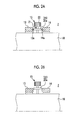
- Figs. 2A and 2B show configurations of the iris ring 13, the ND filter ring 14, and the mechanism section 15.
- the iris ring 13 and the ND filter ring 14 are disposed to be adjacent to each other with a predetermined distance therebetween in the optical axis direction of the lens device 2, and the mechanism section 15 is disposed at a position between the iris ring 13 and the ND filter ring 14.
- the mechanism section 15 has a first gear mechanism 20, which is formed of an odd number of gears, and a supporting portion 21 which supports the first gear mechanism 20.
- the first gear mechanism 20 is formed of a single gear 20a so as to rotatably support the gear 20a. Teeth meshed with the gear 20a are formed on each of the facing side surfaces of the iris ring 13 and the ND filter ring 14 between which the mechanism section 15 is interposed.
- the first gear mechanism 20 is configured to be supported by the supporting portion 21.
- the first gear mechanism 20 and the supporting portion 21 may be integrally formed, and may constitute the first gear mechanism 20.
- the supporting portion 21 is supported by the lens barrel 10 so as to be movable in the diameter direction of the iris ring 13 and the ND filter ring 14, and has an operation portion 22 which projects outside the iris ring 13 and the ND filter ring 14 in the diameter direction.
- a photographer performs an operation to push and pull the operation portion 22 in the diameter direction, whereby the mechanism section 15 is selectively disposed at a first position corresponding to the inside end of the movable range thereof in the diameter direction or a second position corresponding to the outside end of the movable range thereof in the diameter direction.
- the supporting portion 21 may have a structure which is capable of obtaining a click feeling when disposed at the first and second positions.
- the gear 20a is meshed with each of the teeth 13a of the iris ring 13 and the teeth 14a of the ND filter ring 14, and the first gear mechanism 20 is engaged with the iris ring 13 and the ND filter ring 14.
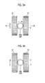
- Figs 3A and 3B show transfer and blocking of the rotations of the iris ring 13 and the ND filter ring 14 performed by the mechanism section 15.
- the outlined arrow indicates a movement (rotation) direction of a driving element which is operated by the photographer
- the solid line arrow indicates a movement (rotation) direction of a driven element.
- the first gear mechanism 20 When the mechanism section 15 is disposed at the first position ( Fig. 3A ), as described above, the first gear mechanism 20 is engaged with the iris ring 13 and the ND filter ring 14. In this state, when any one ring of the iris ring 13 and the ND filter ring 14 is turned, the rotation is transferred to the other ring through the first gear mechanism 20.
- the first gear mechanism 20 is formed of an odd number of gears (the single gear 20a in the example shown in the drawings), and the rotation of one ring is reversed, and is transferred to the other ring.
- the rotation is reversed by the first gear mechanism 20, and is transferred to the ND filter ring 14, and the ND filter ring 14 rotates in a direction of the arrow B opposite to the direction of the arrow A.
- the first gear mechanism 20 may be formed of not only an odd number of gears but also an even number of gears. In this case, due to the turning operation of the iris ring 13, the rotation is transferred, as rotation in the same direction, to the ND filter ring 14 by the first gear mechanism 20, and thus the ND filter ring 14 rotates in the same direction as the iris ring 13.
- the relationship of the increase or the decrease of the amount of transmitted light relative to the rotation direction of the iris ring 13 is set to be the same as the relationship of the increase or the decrease of the amount of transmitted light relative to the rotation direction of the ND filter ring 14, due to the turning operation of the iris ring 13 and reverse rotation of the ND filter ring 14 interlocking therewith, while suppressing the change in the amount of transmitted light, it is possible to adjust the depth of field by adjusting the aperture size of the aperture stop device. Thereby, for example, it is possible to easily obtain the blur condition of the background appropriate for an intention of the photographer even through a manual operation.
- a correspondence relationship between a rotation angle of the iris ring 13 and a light amount ratio, which is a ratio of an amount of exit light to an amount of light incident into the aperture stop device, and a correspondence relationship between a rotation angle of the ND filter ring 14 and the transmittance of the variable light transmission filter are configured to be relations of geometrical progressions which are the same in terms of progressions of ratios of amounts of transmitted light at respective rotation angles based on an amount of unitary angular change. This configuration is desirable since it is possible to keep the amount of transmitted light constant in the above operation.
- the iris ring 13 and the ND filter ring 14 are disposed to be adjacent to each other in the optical axis direction of the lens device 2, and this configuration is appropriate for when both rings 13 and 14 are simultaneously turned.
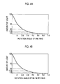
- Figs. 4A and 4B are graphs illustrating examples of relationships of the amounts of transmitted light relative to the respective amounts of operation (rotation angles) of the iris ring 13 and the ND filter ring 14.
- the iris ring 13 is configured such that the amount of transmitted light of the aperture stop device is 50% at the rotation angle ⁇ to the origin position (at which the amount of transmitted light of the aperture stop device is 100%), the amount of transmitted light is 25% at the rotation angle 2 ⁇ , the amount of transmitted light is 12.5% at the rotation angle 3 ⁇ , the amount of transmitted light is 6.3% at the rotation angle 4 ⁇ , ... ( Fig. 4A ).
- the amount of transmitted light of the variable light transmission filter is set to 50% at the rotation angle ⁇ to the origin position (at which amount of transmitted light of the variable light transmission filter is 100%), the amount of transmitted light is set to 25% at the rotation angle 2 ⁇ , the amount of transmitted light is set to 12.5% at the rotation angle 3 ⁇ , the amount of transmitted light is set to 6.3% at the rotation angle 4 ⁇ , ... ( Fig. 4A ). That is, a rotation direction, in which the aperture area of the aperture stop device is increased by the iris ring 13, is the same as a direction in which the transmittance of the variable light transmission filter is increased by the ND filter ring 14.
- the relationships of the amounts of transmitted light relative to the respective amounts of operation (rotation angle) of the iris ring 13 and the ND filter ring 14 are relationships of geometrical progressions which are the same in that a geometrical ratio is 1/2 in terms of progressions of ratios of amounts of transmitted light (100%, 50%, 25%, 7) at respective rotation angles (origin, ⁇ , 2 ⁇ , ...) based on an amount of unitary angular change ⁇ .
- control voltage values corresponding to the rotation angles ⁇ , 2 ⁇ , and 3 ⁇ , ... of the ND filter ring 14 are set, and the voltage values are applied to the electrodes of the variable light transmission filter, thereby achieving the amounts of transmitted light corresponding to the rotation angles.
- the amount of transmitted light of the variable light transmission filter is subjected to feedback control such that the relative relationship between the rotation angle of the ND filter ring 14 and the amount of transmitted light of the variable light transmission filter coincides with the relative relationship between the rotation angle of the iris ring 12 and the amount of transmitted light of the aperture stop device with high accuracy.
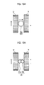
- Figs. 5A and 5B show a configuration of another example of a lens device according to an embodiment of the present invention. It should be noted that the elements common to the above-mentioned lens device 2 are referenced by the same reference numerals and signs, and a description thereof will be omitted or simplified.
- the lens device 102 shown in Figs. 5A and 5B is different from the above-mentioned lens device 2 in that the mechanism section 15 is provided to be rotatable about the same axis as the iris ring 13 and the ND filter ring 14.
- the lens device 102 has a supporting ring 16 which is rotatably provided on the outer circumference of the lens barrel 10 at a position between the iris ring 13 and the ND filter ring 14.
- the supporting ring 16 is provided to be rotatable about the same axis as the iris ring 13 and the ND filter ring 14.
- the supporting portion 21 of the mechanism section 15 is supported by the supporting ring 16 so as to be rotatable in the diameter direction of the iris ring 13 and the ND filter ring 14.
- the mechanism section 15 is selectively disposed at a first position corresponding to the inside end of the movable range thereof in the diameter direction or a second position corresponding to the outside end of the movable range thereof in the diameter direction.
- the first gear mechanism 20 of the mechanism section 15 is engaged with the iris ring 13 and the ND filter ring 14.
- the second position Fig. 5B
- the engagement of the first gear mechanism 20 of the mechanism section 15 with the iris ring 13 and the ND filter ring 14 is released.
- the mechanism section 15, in which the supporting portion 21 is supported by the supporting ring 16 rotates around the rotation axis of the supporting ring 16 in accordance with the rotation of the supporting ring 16.
- Figs. 6A and 6B show transfer of the rotations of the iris ring 13 and the ND filter ring 14 performed by the mechanism section 15.
- the mechanism section 15 When the mechanism section 15 is disposed at the first position, the first gear mechanism 20 of the mechanism section 15 is engaged with the iris ring 13 and the ND filter ring 14. In this state, when any one ring of the iris ring 13 and the ND filter ring 14 is turned, the rotation thereof is reversed by the first gear mechanism 20, and is transferred to the other ring ( Fig. 6A ). Thereby, it is possible to adjust the depth of field by adjusting the aperture size of the aperture stop device while suppressing change in the amount of transmitted light.
- the first gear mechanism 20 of the mechanism section 15 is engaged with the iris ring 13 and the ND filter ring 14.
- the mechanism section 15 is turned around the rotation axis of the supporting ring 16, that is, around the rotation axis of the iris ring 13 and the ND filter ring 14, and then the iris ring 13 and the ND filter ring 14 rotate in the same direction at the same time ( Fig. 6B ).
- both amounts of transmitted light of the aperture stop device and the transmittance variable filter are increased or decreased. As a result, it is possible to enhance adjustability of the amount of transmitted light.
- Fig. 7 shows a configuration of a modified example of the above-mentioned lens device 102.
- the operation portion 22 of the mechanism section 15 is provided to extend in the diameter direction of the supporting ring 16 and to be twistable around the axis passing through the operation portion 22.
- the operation portion 22 is connected to any one gear constituting the first gear mechanism 20, and is configured to rotate the gear on its own axis in accordance with the twisting operation of the operation portion 22.
- the first gear mechanism 20 is formed of the single gear 20a, and the operation portion 22 is connected to the gear 20a.
- Figs 8A and 8B show transfer of rotations of the iris ring 13 and the ND filter ring 14 performed by the mechanism section 15.
- the first gear mechanism 20 of the mechanism section 15 When the mechanism section 15 is disposed at the first position, the first gear mechanism 20 of the mechanism section 15 is engaged with the iris ring 13 and the ND filter ring 14. In this state, when the operation portion 22 of the mechanism section 15 is twisted, in accordance with the twisting operation of the operation portion 22, the gear 20a constituting the first gear mechanism 20 rotates on its own axis, and the rotation thereof is transferred to each of the iris ring 13 and the ND filter ring 14 engaged with the first gear mechanism 20.
- the first gear mechanism 20 is formed of an odd number of gears (the single gear 20a in the example shown in the drawings), and thus the rotation directions of the iris ring 13 and the ND filter ring 14 are opposite to each other.
- the mechanism section 15 is turned around the rotation axis of the supporting ring 16, that is, around the rotation axis of the iris ring 13 and the ND filter ring 14, and then the iris ring 13 and the ND filter ring 14 rotate in the same direction at the same time.
- both amounts of transmitted light of the aperture stop device and the transmittance variable filter are increased or decreased.
- the iris ring 13 and the ND filter ring 14 may rotate in the same direction at the same time, and may rotate in the opposite directions at the same time.
- operation targets are different (in the former case, the mechanism section 15, and in the latter case, the iris ring 13 or the ND filter ring 14).
- rotation can be caused by the operation of the mechanism section 15 (in the former case, by the turning operation of the entire mechanism section 15, and in the latter case, by the twisting operation of the operation portion 22 of the mechanism section 15), and thus operability is improved.
- Figs 9A and 9B show a configuration of another example of a lens device according to an embodiment of the present invention. It should be noted that the elements common to the above-mentioned lens devices 2 and 102 are referenced by the same reference numerals and signs, and a description thereof will be omitted or simplified.
- the mechanism section 15 has the first gear mechanism 20 that is formed of an odd number of gears, a second gear mechanism 23 that is formed of an even number of gears, and the supporting portion 21 that supports the first gear mechanism 20 and the second gear mechanism 23.
- the first gear mechanism 20 is formed of the single gear 20a
- the second gear mechanism 23 is formed of two gears 23a and 23b. Teeth meshed with the gear 20a of the first gear mechanism 20 and one gear 23a of the second gear mechanism 23 are formed on the side surface of the iris ring 13. Teeth meshed with the gear 20a of the first gear mechanism 20 and the other gear 23b of the second gear mechanism 23 are formed on the side surface of the ND filter ring 14.
- the supporting portion 21 is supported by the lens barrel 10 so as to be movable in the diameter direction of the iris ring 13 and the ND filter ring 14, and has the operation portion 22 which projects outside the iris ring 13 and the ND filter ring 14 in the diameter direction.
- a photographer performs an operation to push and pull the operation portion 22 in the diameter direction, whereby the mechanism section 15 is selectively disposed at a first position corresponding to the inside end of the movable range thereof in the diameter direction, a third position corresponding to the outside end of the movable range thereof in the diameter direction, or a second position that is positioned between the first position and the third position.
- the gear 20a of the first gear mechanism 20 is meshed with each of the teeth 13a of the iris ring 13 and the teeth 14a of the ND filter ring 14, and the first gear mechanism 20 is engaged with the iris ring 13 and the ND filter ring 14.
- one gear 23a of the second gear mechanism 23 is meshed with the teeth 13a of the iris ring 13, and the other gear 23b is meshed with the teeth 14a of the ND filter ring 14, and the second gear mechanism 23 is engaged with the iris ring 13 and the ND filter ring 14.
- Figs. 10A and 10B show transfer of the rotations of the iris ring 13 and the ND filter ring 14 performed by the mechanism section 15.
- the first gear mechanism 20 When the mechanism section 15 is disposed at the first position ( Fig. 10A ), as described above, the first gear mechanism 20 is engaged with the iris ring 13 and the ND filter ring 14. In this state, when any one ring of the iris ring 13 and the ND filter ring 14 is turned, the rotation is transferred to the other ring through the first gear mechanism 20.
- the first gear mechanism 20 is formed of an odd number of gears (the single gear 20a in the example shown in the drawings), and the rotation of one ring is reversed, and is transferred to the other ring.
- the second gear mechanism 23 When the mechanism section 15 is disposed at the third position ( Fig. 10B ), as described above, the second gear mechanism 23 is engaged with the iris ring 13 and the ND filter ring 14. In this state, when any one ring of the iris ring 13 and the ND filter ring 14 is turned, the rotation is transferred to the other ring through the second gear mechanism 23.
- the second gear mechanism 23 is formed of an even number of gears (the two gears 23a and 23b in the example shown in the drawings), and the rotation of one ring is not reversed, and is transferred to the other ring as rotation in the same direction.
- the mechanism section 15 When the mechanism section 15 is disposed at the second position, as described above, the engagement of the first gear mechanism 20 and the second gear mechanism 23 with the iris ring 13 and the ND filter ring 14 is released. Accordingly, the iris ring 13 and the ND filter ring 14 are separately operable to be turned in both forward and reverse directions.
- the iris ring 13 and the ND filter ring 14 may rotate in the same direction at the same time, and may rotate in the opposite directions at the same time. In either case, rotation can be caused by the turning operation of any one ring of the iris ring 13 and the ND filter ring 14, and thus operability is excellent.
- Figs. 11 and 12 show a configuration of a modified example of the above-mentioned lens device 202.
- the operation portion 22 of the mechanism section 15 is provided to extend in the diameter direction of the supporting ring 16 and to be twistable around the axis passing through the operation portion 22.
- the operation portion 22 is connected to each of any one gear constituting the first gear mechanism 20 and any one gear constituting the second gear mechanism 23, and is configured to rotate the gears on their own axes in accordance with the twisting operation of the operation portion 22.
- the first gear mechanism 20 is formed of the single gear 20a, and the operation portion 22 is directly connected to the gear 20a.
- the second gear mechanism 23 is formed of the two gears 23a and 23b, and the axes of rotation of the gears 23a and 23b are different from the axis of rotation of the gear 20a of the first gear mechanism 20. Therefore, the operation portion 22 is connected to one gear 23a of the second gear mechanism 23 through gears 24a and 24b.
- Figs. 13A and 13B show transfer of rotations of the iris ring 13 and the ND filter ring 14 performed by the mechanism section 15.
- the first gear mechanism 20 of the mechanism section 15 is engaged with the iris ring 13 and the ND filter ring 14.
- the gear 20a constituting the first gear mechanism 20 rotates on its own axis, and the rotation thereof is transferred to each of the iris ring 13 and the ND filter ring 14 engaged with the first gear mechanism 20.
- the first gear mechanism 20 is formed of an odd number of gears (the single gear 20a in the example shown in the drawings), and thus the rotation directions of the iris ring 13 and the ND filter ring 14 are opposite to each other.
- the second gear mechanism 23 of the mechanism section 15 is engaged with the iris ring 13 and the ND filter ring 14.
- the gear 23a constituting the second gear mechanism 23 rotates on its own axis, and the rotation thereof is transferred to each of the iris ring 13 and the ND filter ring 14 engaged with the second gear mechanism 23.
- the second gear mechanism 23 is formed of an even number of gears (the two gears 23a and 23b in the example shown in the drawings), and the directions of the rotations of the iris ring 13 and the ND filter ring 14 are made to be the same.
- the iris ring 13 and the ND filter ring 14 may rotate in the same direction at the same time, and may rotate in the opposite directions at the same time. In either case, rotation can be caused by the twisting operation of the operation portion 22 of the mechanism section 15, and thus operability is excellent.
- Fig. 14 is a functional block diagram of principal sections of the whole imaging device in which the above-mentioned lens device 2 is mounted on the imaging device main body 1.
- imaging-lenses 31 and 32 an aperture stop device 33 that adjusts the aperture size (aperture area) as shown in for example Fig. 17 , and a variable light transmission filter 34 are built.
- the aperture stop device 33 and the variable light transmission filter 34 are disposed to be close, but the aperture stop device 33 and the variable light transmission filter 34 may be separately disposed at different locations on the optical path of the incident light.
- a dashed line circle X shown in Fig. 14 indicates an outer circumferential portion of the lens barrel 10 of the lens device 2.
- the iris ring 13 which adjusts the aperture size of the aperture stop device 33, and the ND filter ring 14, which adjusts the amount of transmitted light of the variable light transmission filter 34, are disposed to be adjacent.
- the amount of rotation of the iris ring 13 is converted into a driving force in a direction (or an opposite direction) of an arrow 104 shown in Fig. 17 of the aperture stop device 33 through a mechanical or electrical driving mechanism.
- a potentiometer 35 which detects the amount of operation (rotation angle) of the ND filter ring 14, is provided on the inner circumferential portion of the ND filter ring 14.
- An ND filter control section 36 reads the rotation angle which is detected by the potentiometer 35, applies a voltage value according to the rotation angle to an electrode of the variable light transmission filter 34, and controls the amount of transmitted light.
- a transmittance monitor 37 is disposed in the vicinity of the variable light transmission filter 34.
- the transmittance detected by the monitor 37 is fed back to the ND filter control section 36 and is subjected to feedback control so as to be the transmittance (amount of transmitted light) according to the rotation angle detected by the potentiometer 35.
- the transmittance monitor 37 is formed of a light emitting element and a light receiving element, between which the circular disc of the variable light transmission filter 34 is interposed, so as to detect the transmittance of the variable light transmission filter 34 on the basis of the amount of light emitted by the light emitting element and the amount of light received by the light receiving element.
- an imaging device module 38 is built.
- the imaging device module 38 shown in the drawing is formed of: a prism 38a that separates the incident light transmitted through the lens device 2 into optical paths of three colors of red (R), green (G), and blue (B); an imaging device 38R that detects red light (R light) separated by the prism 38a; an imaging device 38G that detects green light (G light) separated by the prism 38a; and an imaging device 38B that detects blue light (B light) separated by the prism 38a.
- the detection signals of the respective imaging devices 38R, 38G, and 38B are subjected to white balance correction by a camera image processing section (CAM) 39, and are then output as, for example, television signals.
- CAM camera image processing section
- a camera image processing section 21 feeds a captured image signal, which is captured by the imaging device module 38, as light amount information back to the ND filter control section 36 of the lens device 2.
- the ND filter control section 36 controls the transmittance of the variable light transmission filter 34 in consideration of also the fed-back information.
- variable light transmission filter 34 keep the transmittance constant at all wavelengths in a imaging wavelength region without wavelength dependency in the transmittance.
- practically the balance of RGB is slightly different, and thus as the transmittance is changed, the balance of RGB is slightly changed.
- the camera image processing section 21 acquire the transmittance information from the ND filter control section 36, and perform white balance correction on the basis of the correction value which is preset using the transmittance information.
- the preset correction value can be obtained by photographing a white object with a light source having a constant intensity while changing the transmittance of the variable light transmission filter 34.
- the imaging device mounted on the imaging device main body 1 is a three-plate imaging device, but may be a single-plate imaging device.
- Fig. 15 is a functional block diagram of principal sections of another example of the imaging device.
- variable light transmission filter for example, the filter, which controls the amount of transmitted light through voltage value control exemplified in JP2006-126504A , is used, but the filter exemplified in JP2007-243928A may be used.
- the filter forms gradation on a transparent circular disc by using a dimming material. That is, the filter is manufactured in a state where the density of the dimming material is adjusted such that, as the rotation angle increases, the transmittance gradually increases, where the transmittance is 0% at the position of the rotation angle of 0 degrees to the central axis and the transmittance is 100% at the position right before the rotation angle of 360 degrees.
- the variable light transmission filter 40 is built into the lens device 2, together with the aperture stop device 33.
- the ND filter control section 36 issues a command to a motor 41 in accordance with the rotation angle which is detected by the potentiometer 35, and thereby controls the rotation angle position of the filter 40.
- the depth of gradation on the incident light optical path of the filter 40 becomes a desired depth, and the amount of light transmitted through the filter according to the rotation position of the ND filter ring 14 is obtained.
- the gradation position of the filter 40 is determined depending on the rotation angle of the filter 40. Hence, it is not necessary to provide a feedback control system using the transmittance monitor 37 of Fig. 14 .
- Fig. 16 is a functional block diagram of principal sections of another example of the imaging device.
- the operation tool (iris ring 13) of the aperture stop device 33 of which the aperture size is variable and the operation tool (ND filter ring) 14 of the variable light transmission filter are disposed on the outer circumferential portion of the lens device 2 so as to be adjacent to each other.
- the aperture stop device and the variable light transmission filter it is not always necessary for the aperture stop device and the variable light transmission filter to be disposed to be close to each other.
- variable light transmission filters 38r, 38g, and 38b are disposed, respectively.
- the transmittances of the variable light transmission filters 38r, 38g, and 38b are controlled by the amount of operation (rotation angle) of the ND filter ring provided on the lens device 2 side.
- the potentiometer 35 that detects the amount of rotation is mounted on the ND filter ring.
- the ND filter control section 36 is configured to transfer the detected value of the amount of rotation to a transmission adjustment circuit 43 on the imaging device main body 1 side.
- the transmission adjustment circuit 24 controls the transmittances of the variable light transmission filters 38r, 38g, and 38b in accordance with the detected value of the potentiometer 35.
- the variable light transmission filter may be built into the lens device 2. It may be possible to adopt a configuration in which whether to use the variable light transmission filter on the imaging device main body 1 side or to use the variable light transmission filter built into the lens device 2 is selected by a switch provided in the lens device 2 and not shown in the drawing. When the variable light transmission filter built into the lens device 2 is not used, the transmittance of the variable light transmission filter is set to 100%.
- the ND filter control section 36 may have a configuration for performing only the function of simply transferring the detected value of the potentiometer 35 to the imaging device main body 1 side.
- a lens device of (1) to (10) to be described as follows is disclosed, and an imaging device of (11) to be described as follows is disclosed.
- a lens device for an imaging device having a imaging-lens and an aperture stop device that adjusts an aperture area including: a lens barrel that houses the imaging-lens and the aperture stop device; a first operation ring that is provided on an outer circumferential portion of the lens barrel at a desired position and is provided to be rotatable in a circumferential direction of the outer circumferential portion about an axis line of the lens barrel as a rotation axis in order to adjust the aperture area of the aperture stop device; a second operation ring that is provided in parallel with the first operation ring and provided to be rotatable in the circumferential direction of the outer circumferential portion about the axis line of the lens barrel as the rotation axis in order to adjust a transmittance of a variable light transmission filter; and a mechanism section that transfers rotations of the first operation ring and the second operation ring to each other and blocks the rotations, in which a rotation direction, in which the aperture area of the aperture stop device is increased by the first operation
- the mechanism section has a first gear mechanism, which is formed of gears, and a supporting portion which supports the first gear mechanism, and in which the supporting portion is provided to be movable, along diameter directions of the first operation ring and the second operation ring, to a plurality of positions that includes a first position, at which the first gear mechanism is engaged with each of the first operation ring and the second operation ring, and a second position at which engagement of the first gear mechanism with each of the first operation ring and the second operation ring is released.
- a correspondence relationship between a rotation angle of the first operation ring and a light amount ratio, which is a ratio of an amount of exit light to an amount of light incident into the aperture stop device, and a correspondence relationship between a rotation angle of the second operation ring and the transmittance of the variable light transmission filter are relations of geometrical progressions which are the same in terms of progressions of ratios of amounts of transmitted light at respective rotation angles based on an amount of unitary angular change.
- variable light transmission filter is mounted on the lens barrel.
- the lens device further including: a monitor that detects the transmittance of the variable light transmission filter; and a control section that performs feedback control on the transmittance of the variable light transmission filter and sets the transmittance, which is detected by the monitor, as a transmittance depending on an amount of an operation of the second operation ring.
- An imaging device including the lens device according to any one of (1) to (10).
Landscapes
- Physics & Mathematics (AREA)
- General Physics & Mathematics (AREA)
- Optics & Photonics (AREA)
- Blocking Light For Cameras (AREA)
- Studio Devices (AREA)
- Lens Barrels (AREA)
- Exposure Control For Cameras (AREA)
- Diaphragms For Cameras (AREA)
Abstract

Description
- The present invention relates to a lens device mounted on a video camera or a television camera. In particular, the present invention relates to a lens device, which has both of an operation tool that manually operates an aperture stop device so as to adjust an amount of incident light and an operation tool that manually adjusts an amount of transmitted light of a variable light transmission filter, and an imaging device mounted with the lens device.
- As the device that adjusts the amount of incident light, an aperture stop (iris) device is generally used. For example, an
aperture stop device 100 shown inFig. 17 is configured such that a plurality of (six, in the example shown in the drawing)aperture stop blades 101, which functions as an iris, is disposed on a circumference and adriving point 102 of eachblade 101 is moved in a direction of anarrow 104 centered on a supportingpoint 103 so as to decrease an aperture area (aperture size) of acenter hole 105 which transmits incident light. - In the
aperture stop device 100, when the amount of incident light is intended to be decreased, thecenter hole 105 is narrowed. However, when a bright outdoor image is photographed at a minimum aperture position, blurring which is caused by a decrease in a resolving power decreased by the effect of the diffraction phenomenon, so-called small aperture blurring may occur, and may deteriorate a quality of a photographed image. - For this reason, as the device that adjusts the amount of incident light, for example, an ND filter disclosed in
JP2007-243928A - Further, a light amount adjustment device disclosed in
JP2006-126504A - By inserting the variable light transmission filter exemplified in
JP2007-243928A JP2006-126504A Fig. 17 , it is possible to avoid occurrence of small aperture blurring even when photographing the bright outdoor image. However, in the variable light transmission filter, it is difficult to perform imaging that blurs the background through adjustment of the depth of field performed by adjusting the aperture stop diameter, the adjustment being regarded as an advantage of the aperture stop device. - That is, both the aperture stop device and the variable light transmission filter are able to adjust the amount of incident light, but both have advantages and disadvantages for other functions.
- For this reason, as disclosed in the following
JP-H09-186922A JP-H05-292392A - In recent years, considerable progress has been made in reduction in manufacturing costs and enhancement in performance of the variable light transmission filter, and thus it is possible to mount both the aperture stop device and the variable light transmission filter on an actual imaging device.
- However, in the lens device mounted on the imaging device, there are multiple adjustment tools (operation tools), such as a magnification adjustment ring and a focus position adjustment ring of the zoom lens, which a photographer operates with only the sense of touch of the hand while viewing a finder device. Hence, when the adjustment tool of the aperture stop device and the adjustment tool of the variable light transmission filter are mounted on the actual device, it is necessary to consider which specific mount form is better to provide a lens device excellent in usability.
- An object of the present invention is to provide a lens device, which is capable of performing various kinds of image capturing appropriate for an intention of a photographer by using the variable light transmission filter and the aperture stop device having in common a function of adjusting the amount of transmitted light and which is excellent in usability, and an imaging device mounted with the lens device.
- (1) A lens device for an imaging device having a imaging-lens and an aperture stop device that adjusts an aperture area, the lens device including: a lens barrel that houses the imaging-lens and the aperture stop device; a first operation ring that is provided on an outer circumferential portion of the lens barrel at a desired position and is provided to be rotatable in a circumferential direction of the outer circumferential portion about an axis line of the lens barrel as a rotation axis in order to adjust the aperture area of the aperture stop device; a second operation ring that is provided in parallel with the first operation ring and provided to be rotatable in the circumferential direction of the outer circumferential portion about the axis line of the lens barrel as the rotation axis in order to adjust a transmittance of a variable light transmission filter; and a mechanism section that transfers rotations of the first operation ring and the second operation ring to each other and blocks the rotations. A rotation direction, in which the aperture area of the aperture stop device is increased by the first operation ring, is the same as a rotation direction in which the transmittance of the variable light transmission filter is increased by the second operation ring. The mechanism section is configured to be able to convert the rotations of the first operation ring and the second operation ring into rotations in directions the same as each other or directions opposite to each other and transfer the rotations.
- (2) An imaging device including the lens device of (1).
- According to the present invention, a photographer, who photographs a moving image of an object with a television camera or a video camera, is able to perform various kinds of exposure control through combination between adjustment of an aperture area of the aperture stop and adjustment of the amount of transmitted light of the variable light transmission filter. Hence, it is possible to photograph images according to various kinds of intention in imaging. Through a turning operation of either one of the first operation ring and the second operation ring and a rotation of the other ring interlocking through the mechanism section, it is possible to adjust the depth of field by adjusting the aperture size of the aperture stop device while suppressing change in the amount of transmitted light. Thereby, through a manual operation, it is possible to easily obtain a blur condition of the background appropriate for the intention of the photographer.
-
-
Fig. 1 is a diagram schematically illustrating a configuration of an example of a lens device and an imaging device mounted with the lens device according to an embodiment of the present invention. -
Figs. 2A and 2B are diagrams illustrating configurations of the first operation ring and the second operation ring of the lens device ofFig. 1 and a mechanism section. -
Figs. 3A and 3B are diagrams illustrating transfer and blocking of rotations of the first operation ring and the second operation ring performed by the mechanism section ofFigs. 2A and 2B . -
Figs. 4A and 4B are graphs illustrating examples of relationships of the amounts of transmitted light relative to the respective amounts of operation (rotation angles) of the first operation ring and the second operation ring in the lens device ofFig. 1 . -
Figs. 5A and 5B are diagrams schematically illustrating a configuration of another example of a lens device according to an embodiment of the present invention. -
Figs. 6A and 6B are diagrams illustrating transfer of rotations of the first operation ring and the second operation ring performed by the mechanism section ofFigs. 5A and 5B . -
Fig. 7 is a diagram schematically illustrating a configuration of a modified example of the lens device ofFigs. 5A and 5B . -
Figs. 8A and 8B are diagrams illustrating transfer of rotations of the first operation ring and the second operation ring performed by the mechanism section ofFig. 7 . -
Figs. 9A and 9B are diagrams schematically illustrating a configuration of another example of a lens device according to an embodiment of the present invention. -
Figs. 10A and 10B are diagrams illustrating transfer of rotations of the first operation ring and the second operation ring performed by the mechanism section ofFigs. 9A and 9B . -
Fig. 11 is a diagram schematically illustrating a configuration of a modified example of the lens device ofFigs. 9A and 9B . -
Fig. 12 is a diagram schematically illustrating a configuration of a mechanism section of the lens device ofFig. 11 . -
Figs. 13A and 13B are diagrams illustrating transfer of rotations of the first operation ring and the second operation ring performed by the mechanism section ofFig. 11 . -
Fig. 14 is a functional block diagram of principal sections of an example of the imaging device according to the embodiment of the present invention. -
Fig. 15 is a functional block diagram of principal sections of another example of the imaging device according to the embodiment of the present invention. -
Fig. 16 is a functional block diagram of principal sections of another example of the imaging device according to the embodiment of the present invention. -
Fig. 17 is a diagram illustrating a configuration of an example of a general aperture stop device that adjusts an aperture area. -
Fig. 1 is a diagram schematically illustrating a configuration of an example of a lens device and an imaging device mounted with the lens device according to an embodiment of the present invention. - A
lens device 2 is mounted on the front part of an imaging device main body 1. - The
lens device 2 has alens barrel 10 that has a barrel shape such as a cylindrical shape. Into thelens barrel 10, imaging-lenses such as a zoom lens and a focus lens and an aperture stop device capable of adjusting the aperture size are built. Further, in the present example, a variable light transmission filter is also built into thelens device 2. A mount section 3 is provided on the base of the lens barrel of thelens device 2. By detachably mounting a connection portion 3a of the mount section 3 on a lens mount section provided in the front part of the imaging device main body 1, thelens device 2 is fixed onto the imaging device main body 1. - In the connection portion 3a, various kinds of connection terminals (electric terminals), which are not shown, are provided. Further, in the lens mount section, connection terminals (electric terminals) corresponding to the various kinds of connection terminals on the lens device side are provided. By mounting the
lens device 2 on the imaging device main body 1, electric connection is made for each corresponding connection terminal. Thereby, a not-shown control unit (CPU) of thelens device 2 acquires necessary information of the imaging device main body 1 side. Further, the control unit (CPU) on the imaging device main body 1 side acquires necessary information of thelens device 2 side. - A photographer 5 views a
finder device 6 with the right eye while carrying the imaging device main body 1 on the right shoulder. Further, the photographer 5 photographs a moving image of an object while fixing the imaging device by holding a grip portion of thelens device 2 with a right hand 7. At this time, the photographer 5 operates various kinds of operation tools provided in thelens device 2 with the sense of touch of the left hand. - In the
lens device 2, for example, a focus position adjustment tool (focus ring 11), which adjusts a focus position of a focus lens, is provided in a ring shape on the lens leading end side (object side) such that it can be turned around the outer circumference of thelens barrel 10. By rotating thefocus ring 11 to an arbitrary angle with the left hand, the photographer 5 adjusts the focus position. - In the middle part of the
lens device 2, the zoom position adjustment tool (zoom ring 12), which adjusts a zoom position of a zoom lens, is provided in a ring shape such that it can be turned around the outer circumference of thelens barrel 10. By rotating thezoom ring 12 to an arbitrary angle with the left hand, the photographer 5 adjusts a zoom ratio. - In the
lens device 2, on the side closer to the imaging device main body 1 than thezoom ring 12, anaperture adjustment tool 13 of the aperture stop device and a lighttransmission adjustment tool 14 of the variable light transmission filter are provided. Theadjustment tools lens device 2, and which one is disposed on the object side is optional. - The aperture stop
position adjustment tool 13 of the aperture stop device is provided as aniris ring 13 such that it can be turned around the outer circumference of thelens barrel 10. The lighttransmission adjustment tool 14 of the variable light transmission filter is formed as anND filter ring 14 according to the shape of theiris ring 13 in the present embodiment, and is provided to be able to be turned around the outer circumference of thelens barrel 10. Theiris ring 13 and theND filter ring 14 are provided to be parallel in a direction perpendicular to the optical axis and be rotatable about the same axis. - When a filter of a type adjusting the amount of transmission by a voltage as disclosed in
JP2006-126504A ND filter ring 14 into a voltage value. Hence, in this case, a potentiometer for rotation angle detection is mounted on an inner circumferential wall of theND filter ring 14. - The aperture stop device adjusted by the
iris ring 13 and the variable light transmission filter adjusted by theND filter ring 14 have in common a function of adjusting the amount of transmitted light, and also have in common the operational feel of bothrings iris ring 13 is set to be the same as a relationship of an increase or a decrease of the amount of transmitted light relative to the rotation direction of theND filter ring 14. - For example, by rotating the
iris ring 13 in the direction of the arrow A (refer toFig. 3 ), the aperture stop device is adjusted to increase the aperture size (to increase the amount of transmitted light). In addition, by rotating theND filter ring 14 in the same direction, the variable light transmission filter is adjusted to increase the transmittance (to increase the amount of transmitted light). - Furthermore, the
lens device 2 is provided with amechanism section 15 that is engaged with theiris ring 13 and theND filter ring 14 so as to transfer rotations of therings rings -
Figs. 2A and 2B show configurations of theiris ring 13, theND filter ring 14, and themechanism section 15. - The
iris ring 13 and theND filter ring 14 are disposed to be adjacent to each other with a predetermined distance therebetween in the optical axis direction of thelens device 2, and themechanism section 15 is disposed at a position between theiris ring 13 and theND filter ring 14. - In
Figs. 2A and 2B , themechanism section 15 has afirst gear mechanism 20, which is formed of an odd number of gears, and a supportingportion 21 which supports thefirst gear mechanism 20. In the example shown in the drawings, thefirst gear mechanism 20 is formed of asingle gear 20a so as to rotatably support thegear 20a. Teeth meshed with thegear 20a are formed on each of the facing side surfaces of theiris ring 13 and theND filter ring 14 between which themechanism section 15 is interposed. It should be noted that thefirst gear mechanism 20 is configured to be supported by the supportingportion 21. However, thefirst gear mechanism 20 and the supportingportion 21 may be integrally formed, and may constitute thefirst gear mechanism 20. - The supporting
portion 21 is supported by thelens barrel 10 so as to be movable in the diameter direction of theiris ring 13 and theND filter ring 14, and has anoperation portion 22 which projects outside theiris ring 13 and theND filter ring 14 in the diameter direction. A photographer performs an operation to push and pull theoperation portion 22 in the diameter direction, whereby themechanism section 15 is selectively disposed at a first position corresponding to the inside end of the movable range thereof in the diameter direction or a second position corresponding to the outside end of the movable range thereof in the diameter direction. The supportingportion 21 may have a structure which is capable of obtaining a click feeling when disposed at the first and second positions. - When the
mechanism section 15 is disposed at the first position (Fig. 2A ), thegear 20a is meshed with each of theteeth 13a of theiris ring 13 and theteeth 14a of theND filter ring 14, and thefirst gear mechanism 20 is engaged with theiris ring 13 and theND filter ring 14. - When the
mechanism section 15 is disposed at the second position (Fig. 2B ), the meshing of thegear 20a with theteeth 13a of theiris ring 13 and theteeth 14a of theND filter ring 14 is released, and the engagement of thefirst gear mechanism 20 with theiris ring 13 and theND filter ring 14 is released. -
Figs 3A and 3B show transfer and blocking of the rotations of theiris ring 13 and theND filter ring 14 performed by themechanism section 15. It should be noted that, in the drawings, the outlined arrow indicates a movement (rotation) direction of a driving element which is operated by the photographer, and the solid line arrow indicates a movement (rotation) direction of a driven element. - When the
mechanism section 15 is disposed at the first position (Fig. 3A ), as described above, thefirst gear mechanism 20 is engaged with theiris ring 13 and theND filter ring 14. In this state, when any one ring of theiris ring 13 and theND filter ring 14 is turned, the rotation is transferred to the other ring through thefirst gear mechanism 20. Thefirst gear mechanism 20 is formed of an odd number of gears (thesingle gear 20a in the example shown in the drawings), and the rotation of one ring is reversed, and is transferred to the other ring. For example, when theiris ring 13 is turned in the direction of the arrow A, the rotation is reversed by thefirst gear mechanism 20, and is transferred to theND filter ring 14, and theND filter ring 14 rotates in a direction of the arrow B opposite to the direction of the arrow A. It should be noted that thefirst gear mechanism 20 may be formed of not only an odd number of gears but also an even number of gears. In this case, due to the turning operation of theiris ring 13, the rotation is transferred, as rotation in the same direction, to theND filter ring 14 by thefirst gear mechanism 20, and thus theND filter ring 14 rotates in the same direction as theiris ring 13. - Since the relationship of the increase or the decrease of the amount of transmitted light relative to the rotation direction of the
iris ring 13 is set to be the same as the relationship of the increase or the decrease of the amount of transmitted light relative to the rotation direction of theND filter ring 14, due to the turning operation of theiris ring 13 and reverse rotation of theND filter ring 14 interlocking therewith, while suppressing the change in the amount of transmitted light, it is possible to adjust the depth of field by adjusting the aperture size of the aperture stop device. Thereby, for example, it is possible to easily obtain the blur condition of the background appropriate for an intention of the photographer even through a manual operation. In addition, as will be described in detail later, a correspondence relationship between a rotation angle of theiris ring 13 and a light amount ratio, which is a ratio of an amount of exit light to an amount of light incident into the aperture stop device, and a correspondence relationship between a rotation angle of theND filter ring 14 and the transmittance of the variable light transmission filter are configured to be relations of geometrical progressions which are the same in terms of progressions of ratios of amounts of transmitted light at respective rotation angles based on an amount of unitary angular change. This configuration is desirable since it is possible to keep the amount of transmitted light constant in the above operation. - When the
mechanism section 15 is disposed at the second position (Fig. 3B ), as described above, the engagement of thefirst gear mechanism 20 with theiris ring 13 and theND filter ring 14 is released. Accordingly, the rotations of theiris ring 13 and theND filter ring 14 are blocked from each other, and theiris ring 13 and theND filter ring 14 are separately operable to be turned in both forward and reverse directions. Accordingly, by turning theiris ring 13 and theND filter ring 14 in the same direction, both amounts of transmitted light of the aperture stop device and the transmittance variable filter are increased or decreased. As a result, it is possible to enhance adjustability of the amount of transmitted light. Thereby, for example, it is possible to perform imaging immediately in response to even an excessively large change in the luminance of the object relative to the adjustability of the amount of transmitted light of the aperture stop device. In particular, theiris ring 13 and theND filter ring 14 are disposed to be adjacent to each other in the optical axis direction of thelens device 2, and this configuration is appropriate for when both rings 13 and 14 are simultaneously turned. -
Figs. 4A and 4B are graphs illustrating examples of relationships of the amounts of transmitted light relative to the respective amounts of operation (rotation angles) of theiris ring 13 and theND filter ring 14. - The
iris ring 13 is configured such that the amount of transmitted light of the aperture stop device is 50% at the rotation angle α to the origin position (at which the amount of transmitted light of the aperture stop device is 100%), the amount of transmitted light is 25% at the rotation angle 2α, the amount of transmitted light is 12.5% at the rotation angle 3α, the amount of transmitted light is 6.3% at the rotation angle 4α, ... (Fig. 4A ). In order to obtain the same operational feel as the operational feel of theiris ring 13, also in theND filter ring 14, the amount of transmitted light of the variable light transmission filter is set to 50% at the rotation angle α to the origin position (at which amount of transmitted light of the variable light transmission filter is 100%), the amount of transmitted light is set to 25% at the rotation angle 2α, the amount of transmitted light is set to 12.5% at the rotation angle 3α, the amount of transmitted light is set to 6.3% at the rotation angle 4α, ... (Fig. 4A ). That is, a rotation direction, in which the aperture area of the aperture stop device is increased by theiris ring 13, is the same as a direction in which the transmittance of the variable light transmission filter is increased by theND filter ring 14. In addition, the relationships of the amounts of transmitted light relative to the respective amounts of operation (rotation angle) of theiris ring 13 and theND filter ring 14 are relationships of geometrical progressions which are the same in that a geometrical ratio is 1/2 in terms of progressions of ratios of amounts of transmitted light (100%, 50%, 25%, ...) at respective rotation angles (origin, α, 2α, ...) based on an amount of unitary angular change α. - For example, as disclosed in
JP2006-126504A ND filter ring 14 are set, and the voltage values are applied to the electrodes of the variable light transmission filter, thereby achieving the amounts of transmitted light corresponding to the rotation angles. - Further, as will be described later, the amount of transmitted light of the variable light transmission filter is subjected to feedback control such that the relative relationship between the rotation angle of the
ND filter ring 14 and the amount of transmitted light of the variable light transmission filter coincides with the relative relationship between the rotation angle of theiris ring 12 and the amount of transmitted light of the aperture stop device with high accuracy. - According to the above-mentioned relationships of the amounts of transmitted light relative to the respective amounts of operation (rotation angles) of the
iris ring 13 and theND filter ring 14, due to the turning operation of theiris ring 13 and the reverse rotation of theND filter ring 14 interlocking therewith through themechanism section 15, the amount of transmitted light is kept constant. It should be noted that in each graph ofFigs. 4A and 4B , the light amount points for each rotation angle α are connected by straight lines, but the effect thereof is the same even in the correspondence between the rotation angle and the light amount in which the points are connected by a curve. -
Figs. 5A and 5B show a configuration of another example of a lens device according to an embodiment of the present invention. It should be noted that the elements common to the above-mentionedlens device 2 are referenced by the same reference numerals and signs, and a description thereof will be omitted or simplified. - The
lens device 102 shown inFigs. 5A and 5B is different from the above-mentionedlens device 2 in that themechanism section 15 is provided to be rotatable about the same axis as theiris ring 13 and theND filter ring 14. - The
lens device 102 has a supportingring 16 which is rotatably provided on the outer circumference of thelens barrel 10 at a position between theiris ring 13 and theND filter ring 14. The supportingring 16 is provided to be rotatable about the same axis as theiris ring 13 and theND filter ring 14. - The supporting
portion 21 of themechanism section 15 is supported by the supportingring 16 so as to be rotatable in the diameter direction of theiris ring 13 and theND filter ring 14. Themechanism section 15 is selectively disposed at a first position corresponding to the inside end of the movable range thereof in the diameter direction or a second position corresponding to the outside end of the movable range thereof in the diameter direction. At the first position (Fig. 5A ), thefirst gear mechanism 20 of themechanism section 15 is engaged with theiris ring 13 and theND filter ring 14. At the second position (Fig. 5B ), the engagement of thefirst gear mechanism 20 of themechanism section 15 with theiris ring 13 and theND filter ring 14 is released. - Further, when a photographer turns the
operation portion 22 around the rotation axis of the supportingring 16, themechanism section 15, in which the supportingportion 21 is supported by the supportingring 16, rotates around the rotation axis of the supportingring 16 in accordance with the rotation of the supportingring 16. -
Figs. 6A and 6B show transfer of the rotations of theiris ring 13 and theND filter ring 14 performed by themechanism section 15. - When the
mechanism section 15 is disposed at the first position, thefirst gear mechanism 20 of themechanism section 15 is engaged with theiris ring 13 and theND filter ring 14. In this state, when any one ring of theiris ring 13 and theND filter ring 14 is turned, the rotation thereof is reversed by thefirst gear mechanism 20, and is transferred to the other ring (Fig. 6A ). Thereby, it is possible to adjust the depth of field by adjusting the aperture size of the aperture stop device while suppressing change in the amount of transmitted light. - Further, the
first gear mechanism 20 of themechanism section 15 is engaged with theiris ring 13 and theND filter ring 14. In this state, themechanism section 15 is turned around the rotation axis of the supportingring 16, that is, around the rotation axis of theiris ring 13 and theND filter ring 14, and then theiris ring 13 and theND filter ring 14 rotate in the same direction at the same time (Fig. 6B ). Thereby, both amounts of transmitted light of the aperture stop device and the transmittance variable filter are increased or decreased. As a result, it is possible to enhance adjustability of the amount of transmitted light. - In the above-mentioned
lens device 2, in order to rotate theiris ring 13 and theND filter ring 14 in the same direction at the same time, it is necessary to turn the two rings of theiris ring 13 and theND filter ring 14 at the same time in the state where themechanism section 15 is disposed at the second position. However, according to thelens device 102 of the present embodiment, simply the turning operation of themechanism section 15 is sufficient, and thus operability is improved. -
Fig. 7 shows a configuration of a modified example of the above-mentionedlens device 102. - In the
lens device 102 shown inFig. 7 , theoperation portion 22 of themechanism section 15 is provided to extend in the diameter direction of the supportingring 16 and to be twistable around the axis passing through theoperation portion 22. In addition, theoperation portion 22 is connected to any one gear constituting thefirst gear mechanism 20, and is configured to rotate the gear on its own axis in accordance with the twisting operation of theoperation portion 22. In the example shown in the drawing, thefirst gear mechanism 20 is formed of thesingle gear 20a, and theoperation portion 22 is connected to thegear 20a. -
Figs 8A and 8B show transfer of rotations of theiris ring 13 and theND filter ring 14 performed by themechanism section 15. - When the
mechanism section 15 is disposed at the first position, thefirst gear mechanism 20 of themechanism section 15 is engaged with theiris ring 13 and theND filter ring 14. In this state, when theoperation portion 22 of themechanism section 15 is twisted, in accordance with the twisting operation of theoperation portion 22, thegear 20a constituting thefirst gear mechanism 20 rotates on its own axis, and the rotation thereof is transferred to each of theiris ring 13 and theND filter ring 14 engaged with thefirst gear mechanism 20. Here, thefirst gear mechanism 20 is formed of an odd number of gears (thesingle gear 20a in the example shown in the drawings), and thus the rotation directions of theiris ring 13 and theND filter ring 14 are opposite to each other. In other words, the rotation of theiris ring 13 is reversed by thefirst gear mechanism 20, and is transferred to theND filter ring 14. Thereby, it is possible to adjust the depth of field by adjusting the aperture size of the aperture stop device while suppressing change in the amount of transmitted light. - Further, the
mechanism section 15 is turned around the rotation axis of the supportingring 16, that is, around the rotation axis of theiris ring 13 and theND filter ring 14, and then theiris ring 13 and theND filter ring 14 rotate in the same direction at the same time. Thereby, both amounts of transmitted light of the aperture stop device and the transmittance variable filter are increased or decreased. As a result, it is possible to enhance adjustability of the amount of transmitted light. - In the
lens device 102 shown inFigs. 5A and 5B , theiris ring 13 and theND filter ring 14 may rotate in the same direction at the same time, and may rotate in the opposite directions at the same time. In the above cases, operation targets are different (in the former case, themechanism section 15, and in the latter case, theiris ring 13 or the ND filter ring 14). In contrast, in thelens device 102 shownFig. 7 , in either case, rotation can be caused by the operation of the mechanism section 15 (in the former case, by the turning operation of theentire mechanism section 15, and in the latter case, by the twisting operation of theoperation portion 22 of the mechanism section 15), and thus operability is improved. -
Figs 9A and 9B show a configuration of another example of a lens device according to an embodiment of the present invention. It should be noted that the elements common to the above-mentionedlens devices - In the
lens device 202 shown inFigs. 9A and 9B , themechanism section 15 has thefirst gear mechanism 20 that is formed of an odd number of gears, asecond gear mechanism 23 that is formed of an even number of gears, and the supportingportion 21 that supports thefirst gear mechanism 20 and thesecond gear mechanism 23. In the example shown in the drawing, thefirst gear mechanism 20 is formed of thesingle gear 20a, and thesecond gear mechanism 23 is formed of twogears gear 20a of thefirst gear mechanism 20 and onegear 23a of thesecond gear mechanism 23 are formed on the side surface of theiris ring 13. Teeth meshed with thegear 20a of thefirst gear mechanism 20 and theother gear 23b of thesecond gear mechanism 23 are formed on the side surface of theND filter ring 14. - The supporting
portion 21 is supported by thelens barrel 10 so as to be movable in the diameter direction of theiris ring 13 and theND filter ring 14, and has theoperation portion 22 which projects outside theiris ring 13 and theND filter ring 14 in the diameter direction. A photographer performs an operation to push and pull theoperation portion 22 in the diameter direction, whereby themechanism section 15 is selectively disposed at a first position corresponding to the inside end of the movable range thereof in the diameter direction, a third position corresponding to the outside end of the movable range thereof in the diameter direction, or a second position that is positioned between the first position and the third position. - When the
mechanism section 15 is disposed at the first position (Fig. 9A ), thegear 20a of thefirst gear mechanism 20 is meshed with each of theteeth 13a of theiris ring 13 and theteeth 14a of theND filter ring 14, and thefirst gear mechanism 20 is engaged with theiris ring 13 and theND filter ring 14. - When the
mechanism section 15 is disposed at the third position (Fig. 9B ), onegear 23a of thesecond gear mechanism 23 is meshed with theteeth 13a of theiris ring 13, and theother gear 23b is meshed with theteeth 14a of theND filter ring 14, and thesecond gear mechanism 23 is engaged with theiris ring 13 and theND filter ring 14. - When the
mechanism section 15 is disposed at the second position (Fig. 9C ), the meshing of thegears teeth 13a of theiris ring 13 is released, the meshing of thegears teeth 14a of theND filter ring 14 is released, and the engagement of thefirst gear mechanism 20 and thesecond gear mechanism 23 with theiris ring 13 and theND filter ring 14 is released. -
Figs. 10A and 10B show transfer of the rotations of theiris ring 13 and theND filter ring 14 performed by themechanism section 15. - When the
mechanism section 15 is disposed at the first position (Fig. 10A ), as described above, thefirst gear mechanism 20 is engaged with theiris ring 13 and theND filter ring 14. In this state, when any one ring of theiris ring 13 and theND filter ring 14 is turned, the rotation is transferred to the other ring through thefirst gear mechanism 20. Thefirst gear mechanism 20 is formed of an odd number of gears (thesingle gear 20a in the example shown in the drawings), and the rotation of one ring is reversed, and is transferred to the other ring. - When the
mechanism section 15 is disposed at the third position (Fig. 10B ), as described above, thesecond gear mechanism 23 is engaged with theiris ring 13 and theND filter ring 14. In this state, when any one ring of theiris ring 13 and theND filter ring 14 is turned, the rotation is transferred to the other ring through thesecond gear mechanism 23. Thesecond gear mechanism 23 is formed of an even number of gears (the twogears - When the
mechanism section 15 is disposed at the second position, as described above, the engagement of thefirst gear mechanism 20 and thesecond gear mechanism 23 with theiris ring 13 and theND filter ring 14 is released. Accordingly, theiris ring 13 and theND filter ring 14 are separately operable to be turned in both forward and reverse directions. - According to the above-mentioned configuration, the
iris ring 13 and theND filter ring 14 may rotate in the same direction at the same time, and may rotate in the opposite directions at the same time. In either case, rotation can be caused by the turning operation of any one ring of theiris ring 13 and theND filter ring 14, and thus operability is excellent. -
Figs. 11 and12 show a configuration of a modified example of the above-mentionedlens device 202. - In the
lens device 202 shown inFigs. 11 and12 , theoperation portion 22 of themechanism section 15 is provided to extend in the diameter direction of the supportingring 16 and to be twistable around the axis passing through theoperation portion 22. In addition, theoperation portion 22 is connected to each of any one gear constituting thefirst gear mechanism 20 and any one gear constituting thesecond gear mechanism 23, and is configured to rotate the gears on their own axes in accordance with the twisting operation of theoperation portion 22. - In the example shown in the drawing, the
first gear mechanism 20 is formed of thesingle gear 20a, and theoperation portion 22 is directly connected to thegear 20a. On the other hand, thesecond gear mechanism 23 is formed of the twogears gears gear 20a of thefirst gear mechanism 20. Therefore, theoperation portion 22 is connected to onegear 23a of thesecond gear mechanism 23 throughgears 24a and 24b. -
Figs. 13A and 13B show transfer of rotations of theiris ring 13 and theND filter ring 14 performed by themechanism section 15. - When the
mechanism section 15 is disposed at the first position (Fig. 13A ), thefirst gear mechanism 20 of themechanism section 15 is engaged with theiris ring 13 and theND filter ring 14. In this state, when theoperation portion 22 of themechanism section 15 is twisted, in accordance with the twisting operation of theoperation portion 22, thegear 20a constituting thefirst gear mechanism 20 rotates on its own axis, and the rotation thereof is transferred to each of theiris ring 13 and theND filter ring 14 engaged with thefirst gear mechanism 20. Here, thefirst gear mechanism 20 is formed of an odd number of gears (thesingle gear 20a in the example shown in the drawings), and thus the rotation directions of theiris ring 13 and theND filter ring 14 are opposite to each other. - When the
mechanism section 15 is disposed at the third position (Fig. 13B ), thesecond gear mechanism 23 of themechanism section 15 is engaged with theiris ring 13 and theND filter ring 14. In this state, when theoperation portion 22 of themechanism section 15 is twisted, in accordance with the twisting operation of theoperation portion 22, thegear 23a constituting thesecond gear mechanism 23 rotates on its own axis, and the rotation thereof is transferred to each of theiris ring 13 and theND filter ring 14 engaged with thesecond gear mechanism 23. Thesecond gear mechanism 23 is formed of an even number of gears (the twogears iris ring 13 and theND filter ring 14 are made to be the same. - According to the above-mentioned configuration, the
iris ring 13 and theND filter ring 14 may rotate in the same direction at the same time, and may rotate in the opposite directions at the same time. In either case, rotation can be caused by the twisting operation of theoperation portion 22 of themechanism section 15, and thus operability is excellent. -
Fig. 14 is a functional block diagram of principal sections of the whole imaging device in which the above-mentionedlens device 2 is mounted on the imaging device main body 1. - Into the
lens device 2, imaging-lenses aperture stop device 33 that adjusts the aperture size (aperture area) as shown in for exampleFig. 17 , and a variablelight transmission filter 34 are built. In this example, theaperture stop device 33 and the variablelight transmission filter 34 are disposed to be close, but theaperture stop device 33 and the variablelight transmission filter 34 may be separately disposed at different locations on the optical path of the incident light. - A dashed line circle X shown in
Fig. 14 indicates an outer circumferential portion of thelens barrel 10 of thelens device 2. On the outer circumferential portion of thelens device 2, theiris ring 13, which adjusts the aperture size of theaperture stop device 33, and theND filter ring 14, which adjusts the amount of transmitted light of the variablelight transmission filter 34, are disposed to be adjacent. The amount of rotation of theiris ring 13 is converted into a driving force in a direction (or an opposite direction) of anarrow 104 shown inFig. 17 of theaperture stop device 33 through a mechanical or electrical driving mechanism. - On the inner circumferential portion of the
ND filter ring 14, apotentiometer 35, which detects the amount of operation (rotation angle) of theND filter ring 14, is provided. An NDfilter control section 36 reads the rotation angle which is detected by thepotentiometer 35, applies a voltage value according to the rotation angle to an electrode of the variablelight transmission filter 34, and controls the amount of transmitted light. - A
transmittance monitor 37 is disposed in the vicinity of the variablelight transmission filter 34. The transmittance detected by themonitor 37 is fed back to the NDfilter control section 36 and is subjected to feedback control so as to be the transmittance (amount of transmitted light) according to the rotation angle detected by thepotentiometer 35. - The transmittance monitor 37 is formed of a light emitting element and a light receiving element, between which the circular disc of the variable
light transmission filter 34 is interposed, so as to detect the transmittance of the variablelight transmission filter 34 on the basis of the amount of light emitted by the light emitting element and the amount of light received by the light receiving element. - Into the imaging device main body 1, an
imaging device module 38 is built. Theimaging device module 38 shown in the drawing is formed of: aprism 38a that separates the incident light transmitted through thelens device 2 into optical paths of three colors of red (R), green (G), and blue (B); animaging device 38R that detects red light (R light) separated by theprism 38a; animaging device 38G that detects green light (G light) separated by theprism 38a; and animaging device 38B that detects blue light (B light) separated by theprism 38a. - The detection signals of the
respective imaging devices - A camera
image processing section 21 feeds a captured image signal, which is captured by theimaging device module 38, as light amount information back to the NDfilter control section 36 of thelens device 2. The NDfilter control section 36 controls the transmittance of the variablelight transmission filter 34 in consideration of also the fed-back information. - Further, it is ideal that the variable
light transmission filter 34 keep the transmittance constant at all wavelengths in a imaging wavelength region without wavelength dependency in the transmittance. However, practically the balance of RGB is slightly different, and thus as the transmittance is changed, the balance of RGB is slightly changed. Hence, it is desirable that the cameraimage processing section 21 acquire the transmittance information from the NDfilter control section 36, and perform white balance correction on the basis of the correction value which is preset using the transmittance information. The preset correction value can be obtained by photographing a white object with a light source having a constant intensity while changing the transmittance of the variablelight transmission filter 34. - It should be noted that, in the imaging device of
Fig. 14 , the imaging device mounted on the imaging device main body 1 is a three-plate imaging device, but may be a single-plate imaging device. -
Fig. 15 is a functional block diagram of principal sections of another example of the imaging device. - In the imaging device shown in
Fig. 14 , as the variable light transmission filter, for example, the filter, which controls the amount of transmitted light through voltage value control exemplified inJP2006-126504A JP2007-243928A - The variable
light transmission filter 40 is built into thelens device 2, together with theaperture stop device 33. In addition, the NDfilter control section 36 issues a command to amotor 41 in accordance with the rotation angle which is detected by thepotentiometer 35, and thereby controls the rotation angle position of thefilter 40. Thereby, the depth of gradation on the incident light optical path of thefilter 40 becomes a desired depth, and the amount of light transmitted through the filter according to the rotation position of theND filter ring 14 is obtained. In this configuration, the gradation position of thefilter 40 is determined depending on the rotation angle of thefilter 40. Hence, it is not necessary to provide a feedback control system using the transmittance monitor 37 ofFig. 14 . -
Fig. 16 is a functional block diagram of principal sections of another example of the imaging device. - As described above, the operation tool (iris ring 13) of the
aperture stop device 33 of which the aperture size is variable and the operation tool (ND filter ring) 14 of the variable light transmission filter are disposed on the outer circumferential portion of thelens device 2 so as to be adjacent to each other. However, it is not always necessary for the aperture stop device and the variable light transmission filter to be disposed to be close to each other. - In the imaging device shown in
Fig. 16 , there is thelens device 2 mounted on the imaging device main body 1 that has the built-in imaging device provided with the variable light transmission filter. In front of theimaging devices light transmission filters light transmission filters lens device 2 side. - The
potentiometer 35 that detects the amount of rotation is mounted on the ND filter ring. In addition, the NDfilter control section 36 is configured to transfer the detected value of the amount of rotation to atransmission adjustment circuit 43 on the imaging device main body 1 side. The transmission adjustment circuit 24 controls the transmittances of the variablelight transmission filters potentiometer 35. - In the imaging device shown in
Fig. 16 , the variable light transmission filter may be built into thelens device 2. It may be possible to adopt a configuration in which whether to use the variable light transmission filter on the imaging device main body 1 side or to use the variable light transmission filter built into thelens device 2 is selected by a switch provided in thelens device 2 and not shown in the drawing. When the variable light transmission filter built into thelens device 2 is not used, the transmittance of the variable light transmission filter is set to 100%. The NDfilter control section 36 may have a configuration for performing only the function of simply transferring the detected value of thepotentiometer 35 to the imaging device main body 1 side. - As described above, in the present specification, a lens device of (1) to (10) to be described as follows is disclosed, and an imaging device of (11) to be described as follows is disclosed.
- (1) a lens device for an imaging device having a imaging-lens and an aperture stop device that adjusts an aperture area, the lens device including: a lens barrel that houses the imaging-lens and the aperture stop device; a first operation ring that is provided on an outer circumferential portion of the lens barrel at a desired position and is provided to be rotatable in a circumferential direction of the outer circumferential portion about an axis line of the lens barrel as a rotation axis in order to adjust the aperture area of the aperture stop device; a second operation ring that is provided in parallel with the first operation ring and provided to be rotatable in the circumferential direction of the outer circumferential portion about the axis line of the lens barrel as the rotation axis in order to adjust a transmittance of a variable light transmission filter; and a mechanism section that transfers rotations of the first operation ring and the second operation ring to each other and blocks the rotations, in which a rotation direction, in which the aperture area of the aperture stop device is increased by the first operation ring, is the same as a rotation direction in which the transmittance of the variable light transmission filter is increased by the second operation ring, and in which the mechanism section is configured to be able to convert the rotations of the first operation ring and the second operation ring into rotations in directions the same as each other or directions opposite to each other and transfer the rotations.
- (2) The lens device according to (1), in which the mechanism section has a first gear mechanism, which is formed of gears, and a supporting portion which supports the first gear mechanism, and in which the supporting portion is provided to be movable, along diameter directions of the first operation ring and the second operation ring, to a plurality of positions that includes a first position, at which the first gear mechanism is engaged with each of the first operation ring and the second operation ring, and a second position at which engagement of the first gear mechanism with each of the first operation ring and the second operation ring is released.
- (3) The lens device according to (2), in which the mechanism section is configured to be able to transfer the rotations of the first operation ring and the second operation ring as rotations in the directions the same as each other.
- (4) The lens device according to (3), in which the supporting portion has an operation portion that is provided to be operable to revolve around rotation axes of the first operation ring and the second operation ring and causes any one of the gears of the first gear mechanism to rotate on its own axis.
- (5) The lens device according to (3), in which the mechanism section further has a second gear mechanism which is formed of gears supported by the supporting portion, and in which the plurality of positions, to which the supporting portion is movable, further includes a third position at which the second gear mechanism is engaged with each of the first operation ring and the second operation ring.
- (6) The lens device according to (5), in which the supporting portion has an operation portion that causes any one of the gears of the first gear mechanism and any one of the gears of the second gear mechanism to rotate on their own axes.
- (7) The lens device according to any one of (1) to (6), in which a correspondence relationship between a rotation angle of the first operation ring and a light amount ratio, which is a ratio of an amount of exit light to an amount of light incident into the aperture stop device, and a correspondence relationship between a rotation angle of the second operation ring and the transmittance of the variable light transmission filter are relations of geometrical progressions which are the same in terms of progressions of ratios of amounts of transmitted light at respective rotation angles based on an amount of unitary angular change.
- (8) The lens device according to any one of (1) to (7), in which the variable light transmission filter is mounted on the lens barrel.
- (9) The lens device according to (8), further including: a monitor that detects the transmittance of the variable light transmission filter; and a control section that performs feedback control on the transmittance of the variable light transmission filter and sets the transmittance, which is detected by the monitor, as a transmittance depending on an amount of an operation of the second operation ring.
- (10) The lens device according to any one of (1) to (7), in which the control section in the imaging device transmits a signal based on the amount of the operation of the second operation ring to the imaging device, and controls the transmittance of the variable light transmission filter provided in the imaging device.
- (11) An imaging device including the lens device according to any one of (1) to (10).
Claims (11)
- A lens device for an imaging device having a imaging-lens and an aperture stop device that adjusts an aperture area, the lens device comprising:a lens barrel that houses the imaging-lens and the aperture stop device;a first operation ring that is provided on an outer circumferential portion of the lens barrel at a desired position and is provided to be rotatable in a circumferential direction of the outer circumferential portion about an axis line of the lens barrel as a rotation axis in order to adjust the aperture area of the aperture stop device;a second operation ring that is provided in parallel with the first operation ring and provided to be rotatable in the circumferential direction of the outer circumferential portion about the axis line of the lens barrel as the rotation axis in order to adjust a transmittance of a variable light transmission filter; anda mechanism section that transfers rotations of the first operation ring and the second operation ring to each other and blocks the rotations,wherein a rotation direction, in which the aperture area of the aperture stop device is increased by the first operation ring, is the same as a rotation direction in which the transmittance of the variable light transmission filter is increased by the second operation ring, andwherein the mechanism section is configured to be able to convert the rotations of the first operation ring and the second operation ring into rotations in directions the same as each other or directions opposite to each other and transfer the rotations.
- The lens device according to claim 1,
wherein the mechanism section has a first gear mechanism, which is formed of gears, and a supporting portion which supports the first gear mechanism, and
wherein the supporting portion is provided to be movable, along diameter directions of the first operation ring and the second operation ring, to a plurality of positions that includes a first position, at which the first gear mechanism is engaged with each of the first operation ring and the second operation ring, and a second position at which engagement of the first gear mechanism with each of the first operation ring and the second operation ring is released. - The lens device according to claim 2,
wherein the mechanism section is configured to be able to transfer the rotations 8 of the first operation ring and the second operation ring as rotations in the directions the same as each other. - The lens device according to claim 3,
wherein the supporting portion has an operation portion that is provided to be operable to revolve around rotation axes of the first operation ring and the second operation ring and causes any one of the gears of the first gear mechanism to rotate on its own axis. - The lens device according to claim 3,
wherein the mechanism section further has a second gear mechanism which is formed of gears supported by the supporting portion, and
wherein the plurality of positions, to which the supporting portion is movable, further includes a third position at which the second gear mechanism is engaged with each of the first operation ring and the second operation ring. - The lens device according to claim 5,
wherein the supporting portion has an operation portion that causes any one of the gears of the first gear mechanism and any one of the gears of the second gear mechanism to rotate on their own axes. - The lens device according to any one of claims 1 to 6,
wherein a correspondence relationship between a rotation angle of the first operation ring and a light amount ratio, which is a ratio of an amount of exit light to an amount of light incident into the aperture stop device, and a correspondence relationship between a rotation angle of the second operation ring and the transmittance of the variable light transmission filter are relations of geometrical progressions which are the same in terms of progressions of ratios of amounts of transmitted light at respective rotation angles based on an amount of unitary angular change. - The lens device according to any one of claims 1 to 7,
wherein the variable light transmission filter is mounted on the lens barrel. - The lens device according to claim 8, further comprising:a monitor that detects the transmittance of the variable light transmission filter; anda control section that performs feedback control on the transmittance of the variable light transmission filter and sets the transmittance, which is detected by the monitor, as a transmittance depending on an amount of an operation of the second operation ring.
- The lens device according to any one of claims 1 to 7,
wherein the control section in the imaging device transmits a signal based on the amount of the operation of the second operation ring to the imaging device, and controls the transmittance of the variable light transmission filter provided in the imaging device. - An imaging device comprising the lens device according to any one of claims 1 to 10.
Applications Claiming Priority (2)
| Application Number | Priority Date | Filing Date | Title |
|---|---|---|---|
| JP2011218530 | 2011-09-30 | ||
| PCT/JP2012/074723 WO2013047591A1 (en) | 2011-09-30 | 2012-09-26 | Lens device, and imaging device fitted with said lens device |
Publications (3)
| Publication Number | Publication Date |
|---|---|
| EP2762940A1 true EP2762940A1 (en) | 2014-08-06 |
| EP2762940A4 EP2762940A4 (en) | 2015-05-06 |
| EP2762940B1 EP2762940B1 (en) | 2020-09-23 |
Family
ID=47995621
Family Applications (1)
| Application Number | Title | Priority Date | Filing Date |
|---|---|---|---|
| EP12836700.0A Active EP2762940B1 (en) | 2011-09-30 | 2012-09-26 | Lens device, and imaging device fitted with said lens device |
Country Status (5)
| Country | Link |
|---|---|
| US (1) | US9030763B2 (en) |
| EP (1) | EP2762940B1 (en) |
| JP (1) | JP5493057B2 (en) |
| CN (1) | CN103827721B (en) |
| WO (1) | WO2013047591A1 (en) |
Families Citing this family (4)
| Publication number | Priority date | Publication date | Assignee | Title |
|---|---|---|---|---|
| CN106769871A (en) * | 2016-12-30 | 2017-05-31 | 武汉六九传感科技有限公司 | A kind of high performance gas absorption cell |
| WO2020235166A1 (en) * | 2019-05-21 | 2020-11-26 | ソニー株式会社 | Imaging device, transmittance instruction device, transmittance control method, and program |
| CN113777731A (en) * | 2021-08-11 | 2021-12-10 | 中国工程物理研究院应用电子学研究所 | Coaxial reverse ring type continuous variable density attenuator device and working method thereof |
| CN113867076B (en) * | 2021-11-08 | 2023-04-28 | Oppo广东移动通信有限公司 | Apodization filter, preparation method thereof and related products |
Family Cites Families (11)
| Publication number | Priority date | Publication date | Assignee | Title |
|---|---|---|---|---|
| JPH05292392A (en) | 1992-04-13 | 1993-11-05 | Sony Corp | Light quantity adjusting device for video camera |
| JPH09186922A (en) | 1996-01-08 | 1997-07-15 | Canon Inc | Imaging device |
| DE10016925A1 (en) * | 2000-04-05 | 2001-10-11 | Zeiss Carl | Iris diaphragm |
| JP2005070431A (en) * | 2003-08-25 | 2005-03-17 | Canon Inc | Light amount adjusting device and photographing device |
| KR101018380B1 (en) * | 2004-04-23 | 2011-03-02 | 삼성전자주식회사 | Aperture device and aperture drive device, camera unit and aperture control method |
| JP2006126504A (en) | 2004-10-28 | 2006-05-18 | Alps Electric Co Ltd | Light quantity adjustment apparatus |
| JP2007243928A (en) | 2006-02-09 | 2007-09-20 | Nippon Hoso Kyokai <Nhk> | Gradation ND filter unit for TV camera, ND adapter and TV camera |
| JP4743875B2 (en) * | 2006-06-20 | 2011-08-10 | キヤノン株式会社 | Optical equipment |
| JP2009251557A (en) * | 2008-04-11 | 2009-10-29 | Panasonic Corp | Imaging apparatus |
| JP2011049737A (en) * | 2009-08-26 | 2011-03-10 | Canon Inc | Imaging apparatus and exposure control method thereof |
| JP2011090033A (en) * | 2009-10-20 | 2011-05-06 | Sony Corp | Lens barrel, image capturing apparatus, and method for controlling the same |
-
2012
- 2012-09-26 EP EP12836700.0A patent/EP2762940B1/en active Active
- 2012-09-26 JP JP2013536332A patent/JP5493057B2/en not_active Expired - Fee Related
- 2012-09-26 CN CN201280048017.3A patent/CN103827721B/en not_active Expired - Fee Related
- 2012-09-26 WO PCT/JP2012/074723 patent/WO2013047591A1/en not_active Ceased
-
2014
- 2014-03-31 US US14/230,814 patent/US9030763B2/en not_active Expired - Fee Related
Also Published As
| Publication number | Publication date |
|---|---|
| WO2013047591A1 (en) | 2013-04-04 |
| JPWO2013047591A1 (en) | 2015-03-26 |
| JP5493057B2 (en) | 2014-05-14 |
| EP2762940B1 (en) | 2020-09-23 |
| US20140313600A1 (en) | 2014-10-23 |
| US9030763B2 (en) | 2015-05-12 |
| CN103827721A (en) | 2014-05-28 |
| EP2762940A4 (en) | 2015-05-06 |
| CN103827721B (en) | 2016-06-08 |
Similar Documents
| Publication | Publication Date | Title |
|---|---|---|
| CN103765274B (en) | Lens device and imaging device having said lens device | |
| JP2009258618A (en) | Filter switching device, photographing lens, camera and image pickup system | |
| JP2007243928A (en) | Gradation ND filter unit for TV camera, ND adapter and TV camera | |
| US11003047B2 (en) | Lens barrel, lens driving device, and image pickup apparatus | |
| US10088671B2 (en) | Transmitted light volume adjusting apparatus and transmitted light volume adjusting method | |
| US9030763B2 (en) | Lens device and imaging device mounted with the lens device | |
| JP6679286B2 (en) | Lens barrel and optical equipment | |
| CN108027490B (en) | Lens barrel and image pickup apparatus | |
| JP2013109008A (en) | Imaging system | |
| TWI653499B (en) | Filter switching device, aperture device and camera | |
| JP5906435B2 (en) | Camera system, camera body and lens unit | |
| JP6862222B2 (en) | Adapter and camera system | |
| US7570885B2 (en) | Imaging device having a rotatable optical element | |
| US20060291075A1 (en) | An imaging device having a polarizing filter, and a method of controlling rotation of a polarizing filter of an imaging device | |
| JP5536699B2 (en) | Lens device for surveillance camera | |
| JP2020149023A (en) | Lens barrel and imaging device | |
| JP2008085773A (en) | Chromatic aberration correcting imaging apparatus and chromatic aberration correcting method | |
| JP2010171616A (en) | Optical element controller | |
| US7224536B2 (en) | Imaging device having a rotatable optical element | |
| JP5211822B2 (en) | Optical parts and photographing apparatus | |
| US20250284178A1 (en) | Light-amount adjusting apparatus, lens apparatus, and image pickup apparatus | |
| JP2019159019A (en) | Lens device and imaging apparatus | |
| JP2025055557A (en) | Imaging device | |
| JP2025133919A (en) | Operation Module | |
| JP2001311978A (en) | Optical device |
Legal Events
| Date | Code | Title | Description |
|---|---|---|---|
| PUAI | Public reference made under article 153(3) epc to a published international application that has entered the european phase |
Free format text: ORIGINAL CODE: 0009012 |
|
| 17P | Request for examination filed |
Effective date: 20140328 |
|
| AK | Designated contracting states |
Kind code of ref document: A1 Designated state(s): AL AT BE BG CH CY CZ DE DK EE ES FI FR GB GR HR HU IE IS IT LI LT LU LV MC MK MT NL NO PL PT RO RS SE SI SK SM TR |
|
| DAX | Request for extension of the european patent (deleted) | ||
| RA4 | Supplementary search report drawn up and despatched (corrected) |
Effective date: 20150409 |
|
| RIC1 | Information provided on ipc code assigned before grant |
Ipc: G02B 7/02 20060101ALI20150401BHEP Ipc: G02B 7/08 20060101AFI20150401BHEP |
|
| GRAP | Despatch of communication of intention to grant a patent |
Free format text: ORIGINAL CODE: EPIDOSNIGR1 |
|
| STAA | Information on the status of an ep patent application or granted ep patent |
Free format text: STATUS: GRANT OF PATENT IS INTENDED |
|
| INTG | Intention to grant announced |
Effective date: 20190726 |
|
| GRAS | Grant fee paid |
Free format text: ORIGINAL CODE: EPIDOSNIGR3 |
|
| GRAJ | Information related to disapproval of communication of intention to grant by the applicant or resumption of examination proceedings by the epo deleted |
Free format text: ORIGINAL CODE: EPIDOSDIGR1 |
|
| GRAL | Information related to payment of fee for publishing/printing deleted |
Free format text: ORIGINAL CODE: EPIDOSDIGR3 |
|
| STAA | Information on the status of an ep patent application or granted ep patent |
Free format text: STATUS: REQUEST FOR EXAMINATION WAS MADE |
|
| INTC | Intention to grant announced (deleted) | ||
| GRAJ | Information related to disapproval of communication of intention to grant by the applicant or resumption of examination proceedings by the epo deleted |
Free format text: ORIGINAL CODE: EPIDOSDIGR1 |
|
| GRAP | Despatch of communication of intention to grant a patent |
Free format text: ORIGINAL CODE: EPIDOSNIGR1 |
|
| GRAR | Information related to intention to grant a patent recorded |
Free format text: ORIGINAL CODE: EPIDOSNIGR71 |
|
| STAA | Information on the status of an ep patent application or granted ep patent |
Free format text: STATUS: GRANT OF PATENT IS INTENDED |
|
| GRAA | (expected) grant |
Free format text: ORIGINAL CODE: 0009210 |
|
| STAA | Information on the status of an ep patent application or granted ep patent |
Free format text: STATUS: THE PATENT HAS BEEN GRANTED |
|
| INTG | Intention to grant announced |
Effective date: 20200813 |
|
| AK | Designated contracting states |
Kind code of ref document: B1 Designated state(s): AL AT BE BG CH CY CZ DE DK EE ES FI FR GB GR HR HU IE IS IT LI LT LU LV MC MK MT NL NO PL PT RO RS SE SI SK SM TR |
|
| REG | Reference to a national code |
Ref country code: GB Ref legal event code: FG4D |
|
| REG | Reference to a national code |
Ref country code: CH Ref legal event code: EP |
|
| REG | Reference to a national code |
Ref country code: IE Ref legal event code: FG4D |
|
| REG | Reference to a national code |
Ref country code: DE Ref legal event code: R096 Ref document number: 602012072499 Country of ref document: DE Ref country code: AT Ref legal event code: REF Ref document number: 1316977 Country of ref document: AT Kind code of ref document: T Effective date: 20201015 |
|
| PG25 | Lapsed in a contracting state [announced via postgrant information from national office to epo] |
Ref country code: FI Free format text: LAPSE BECAUSE OF FAILURE TO SUBMIT A TRANSLATION OF THE DESCRIPTION OR TO PAY THE FEE WITHIN THE PRESCRIBED TIME-LIMIT Effective date: 20200923 Ref country code: HR Free format text: LAPSE BECAUSE OF FAILURE TO SUBMIT A TRANSLATION OF THE DESCRIPTION OR TO PAY THE FEE WITHIN THE PRESCRIBED TIME-LIMIT Effective date: 20200923 Ref country code: SE Free format text: LAPSE BECAUSE OF FAILURE TO SUBMIT A TRANSLATION OF THE DESCRIPTION OR TO PAY THE FEE WITHIN THE PRESCRIBED TIME-LIMIT Effective date: 20200923 Ref country code: GR Free format text: LAPSE BECAUSE OF FAILURE TO SUBMIT A TRANSLATION OF THE DESCRIPTION OR TO PAY THE FEE WITHIN THE PRESCRIBED TIME-LIMIT Effective date: 20201224 Ref country code: NO Free format text: LAPSE BECAUSE OF FAILURE TO SUBMIT A TRANSLATION OF THE DESCRIPTION OR TO PAY THE FEE WITHIN THE PRESCRIBED TIME-LIMIT Effective date: 20201223 Ref country code: BG Free format text: LAPSE BECAUSE OF FAILURE TO SUBMIT A TRANSLATION OF THE DESCRIPTION OR TO PAY THE FEE WITHIN THE PRESCRIBED TIME-LIMIT Effective date: 20201223 |
|
| REG | Reference to a national code |
Ref country code: AT Ref legal event code: MK05 Ref document number: 1316977 Country of ref document: AT Kind code of ref document: T Effective date: 20200923 |
|
| PG25 | Lapsed in a contracting state [announced via postgrant information from national office to epo] |
Ref country code: LV Free format text: LAPSE BECAUSE OF FAILURE TO SUBMIT A TRANSLATION OF THE DESCRIPTION OR TO PAY THE FEE WITHIN THE PRESCRIBED TIME-LIMIT Effective date: 20200923 Ref country code: RS Free format text: LAPSE BECAUSE OF FAILURE TO SUBMIT A TRANSLATION OF THE DESCRIPTION OR TO PAY THE FEE WITHIN THE PRESCRIBED TIME-LIMIT Effective date: 20200923 |
|
| REG | Reference to a national code |
Ref country code: NL Ref legal event code: MP Effective date: 20200923 |
|
| REG | Reference to a national code |
Ref country code: LT Ref legal event code: MG4D |
|
| RAP4 | Party data changed (patent owner data changed or rights of a patent transferred) |
Owner name: FUJIFILM CORPORATION |
|
| PG25 | Lapsed in a contracting state [announced via postgrant information from national office to epo] |
Ref country code: EE Free format text: LAPSE BECAUSE OF FAILURE TO SUBMIT A TRANSLATION OF THE DESCRIPTION OR TO PAY THE FEE WITHIN THE PRESCRIBED TIME-LIMIT Effective date: 20200923 Ref country code: CZ Free format text: LAPSE BECAUSE OF FAILURE TO SUBMIT A TRANSLATION OF THE DESCRIPTION OR TO PAY THE FEE WITHIN THE PRESCRIBED TIME-LIMIT Effective date: 20200923 Ref country code: NL Free format text: LAPSE BECAUSE OF FAILURE TO SUBMIT A TRANSLATION OF THE DESCRIPTION OR TO PAY THE FEE WITHIN THE PRESCRIBED TIME-LIMIT Effective date: 20200923 Ref country code: PT Free format text: LAPSE BECAUSE OF FAILURE TO SUBMIT A TRANSLATION OF THE DESCRIPTION OR TO PAY THE FEE WITHIN THE PRESCRIBED TIME-LIMIT Effective date: 20210125 Ref country code: LT Free format text: LAPSE BECAUSE OF FAILURE TO SUBMIT A TRANSLATION OF THE DESCRIPTION OR TO PAY THE FEE WITHIN THE PRESCRIBED TIME-LIMIT Effective date: 20200923 Ref country code: SM Free format text: LAPSE BECAUSE OF FAILURE TO SUBMIT A TRANSLATION OF THE DESCRIPTION OR TO PAY THE FEE WITHIN THE PRESCRIBED TIME-LIMIT Effective date: 20200923 Ref country code: RO Free format text: LAPSE BECAUSE OF FAILURE TO SUBMIT A TRANSLATION OF THE DESCRIPTION OR TO PAY THE FEE WITHIN THE PRESCRIBED TIME-LIMIT Effective date: 20200923 |
|
| REG | Reference to a national code |
Ref country code: CH Ref legal event code: PL |
|
| PG25 | Lapsed in a contracting state [announced via postgrant information from national office to epo] |
Ref country code: AL Free format text: LAPSE BECAUSE OF FAILURE TO SUBMIT A TRANSLATION OF THE DESCRIPTION OR TO PAY THE FEE WITHIN THE PRESCRIBED TIME-LIMIT Effective date: 20200923 Ref country code: AT Free format text: LAPSE BECAUSE OF FAILURE TO SUBMIT A TRANSLATION OF THE DESCRIPTION OR TO PAY THE FEE WITHIN THE PRESCRIBED TIME-LIMIT Effective date: 20200923 Ref country code: ES Free format text: LAPSE BECAUSE OF FAILURE TO SUBMIT A TRANSLATION OF THE DESCRIPTION OR TO PAY THE FEE WITHIN THE PRESCRIBED TIME-LIMIT Effective date: 20200923 Ref country code: IS Free format text: LAPSE BECAUSE OF FAILURE TO SUBMIT A TRANSLATION OF THE DESCRIPTION OR TO PAY THE FEE WITHIN THE PRESCRIBED TIME-LIMIT Effective date: 20210123 Ref country code: PL Free format text: LAPSE BECAUSE OF FAILURE TO SUBMIT A TRANSLATION OF THE DESCRIPTION OR TO PAY THE FEE WITHIN THE PRESCRIBED TIME-LIMIT Effective date: 20200923 |
|
| REG | Reference to a national code |
Ref country code: BE Ref legal event code: MM Effective date: 20200930 |
|
| REG | Reference to a national code |
Ref country code: DE Ref legal event code: R097 Ref document number: 602012072499 Country of ref document: DE |
|
| PG25 | Lapsed in a contracting state [announced via postgrant information from national office to epo] |
Ref country code: LU Free format text: LAPSE BECAUSE OF NON-PAYMENT OF DUE FEES Effective date: 20200926 Ref country code: SK Free format text: LAPSE BECAUSE OF FAILURE TO SUBMIT A TRANSLATION OF THE DESCRIPTION OR TO PAY THE FEE WITHIN THE PRESCRIBED TIME-LIMIT Effective date: 20200923 Ref country code: MC Free format text: LAPSE BECAUSE OF FAILURE TO SUBMIT A TRANSLATION OF THE DESCRIPTION OR TO PAY THE FEE WITHIN THE PRESCRIBED TIME-LIMIT Effective date: 20200923 |
|
| PLBE | No opposition filed within time limit |
Free format text: ORIGINAL CODE: 0009261 |
|
| STAA | Information on the status of an ep patent application or granted ep patent |
Free format text: STATUS: NO OPPOSITION FILED WITHIN TIME LIMIT |
|
| GBPC | Gb: european patent ceased through non-payment of renewal fee |
Effective date: 20201223 |
|
| PG25 | Lapsed in a contracting state [announced via postgrant information from national office to epo] |
Ref country code: LI Free format text: LAPSE BECAUSE OF NON-PAYMENT OF DUE FEES Effective date: 20200930 Ref country code: IE Free format text: LAPSE BECAUSE OF NON-PAYMENT OF DUE FEES Effective date: 20200926 Ref country code: SI Free format text: LAPSE BECAUSE OF FAILURE TO SUBMIT A TRANSLATION OF THE DESCRIPTION OR TO PAY THE FEE WITHIN THE PRESCRIBED TIME-LIMIT Effective date: 20200923 Ref country code: BE Free format text: LAPSE BECAUSE OF NON-PAYMENT OF DUE FEES Effective date: 20200930 Ref country code: DK Free format text: LAPSE BECAUSE OF FAILURE TO SUBMIT A TRANSLATION OF THE DESCRIPTION OR TO PAY THE FEE WITHIN THE PRESCRIBED TIME-LIMIT Effective date: 20200923 Ref country code: CH Free format text: LAPSE BECAUSE OF NON-PAYMENT OF DUE FEES Effective date: 20200930 |
|
| 26N | No opposition filed |
Effective date: 20210624 |
|
| PG25 | Lapsed in a contracting state [announced via postgrant information from national office to epo] |
Ref country code: IT Free format text: LAPSE BECAUSE OF FAILURE TO SUBMIT A TRANSLATION OF THE DESCRIPTION OR TO PAY THE FEE WITHIN THE PRESCRIBED TIME-LIMIT Effective date: 20200923 Ref country code: FR Free format text: LAPSE BECAUSE OF NON-PAYMENT OF DUE FEES Effective date: 20201123 |
|
| PG25 | Lapsed in a contracting state [announced via postgrant information from national office to epo] |
Ref country code: GB Free format text: LAPSE BECAUSE OF NON-PAYMENT OF DUE FEES Effective date: 20201223 |
|
| PGFP | Annual fee paid to national office [announced via postgrant information from national office to epo] |
Ref country code: DE Payment date: 20210818 Year of fee payment: 10 |
|
| PG25 | Lapsed in a contracting state [announced via postgrant information from national office to epo] |
Ref country code: IS Free format text: LAPSE BECAUSE OF FAILURE TO SUBMIT A TRANSLATION OF THE DESCRIPTION OR TO PAY THE FEE WITHIN THE PRESCRIBED TIME-LIMIT Effective date: 20210123 Ref country code: TR Free format text: LAPSE BECAUSE OF FAILURE TO SUBMIT A TRANSLATION OF THE DESCRIPTION OR TO PAY THE FEE WITHIN THE PRESCRIBED TIME-LIMIT Effective date: 20200923 Ref country code: MT Free format text: LAPSE BECAUSE OF FAILURE TO SUBMIT A TRANSLATION OF THE DESCRIPTION OR TO PAY THE FEE WITHIN THE PRESCRIBED TIME-LIMIT Effective date: 20200923 Ref country code: CY Free format text: LAPSE BECAUSE OF FAILURE TO SUBMIT A TRANSLATION OF THE DESCRIPTION OR TO PAY THE FEE WITHIN THE PRESCRIBED TIME-LIMIT Effective date: 20200923 |
|
| PG25 | Lapsed in a contracting state [announced via postgrant information from national office to epo] |
Ref country code: MK Free format text: LAPSE BECAUSE OF FAILURE TO SUBMIT A TRANSLATION OF THE DESCRIPTION OR TO PAY THE FEE WITHIN THE PRESCRIBED TIME-LIMIT Effective date: 20200923 |
|
| REG | Reference to a national code |
Ref country code: DE Ref legal event code: R119 Ref document number: 602012072499 Country of ref document: DE |
|
| PG25 | Lapsed in a contracting state [announced via postgrant information from national office to epo] |
Ref country code: DE Free format text: LAPSE BECAUSE OF NON-PAYMENT OF DUE FEES Effective date: 20230401 |