EP2762904A1 - Electronic power meter for detecting an n phase current based on waveform superposition of a three phase input current, and n phase current detecting method using same - Google Patents
Electronic power meter for detecting an n phase current based on waveform superposition of a three phase input current, and n phase current detecting method using same Download PDFInfo
- Publication number
- EP2762904A1 EP2762904A1 EP20110873445 EP11873445A EP2762904A1 EP 2762904 A1 EP2762904 A1 EP 2762904A1 EP 20110873445 EP20110873445 EP 20110873445 EP 11873445 A EP11873445 A EP 11873445A EP 2762904 A1 EP2762904 A1 EP 2762904A1
- Authority
- EP
- European Patent Office
- Prior art keywords
- phase
- current
- sampling
- values
- calculating
- Prior art date
- Legal status (The legal status is an assumption and is not a legal conclusion. Google has not performed a legal analysis and makes no representation as to the accuracy of the status listed.)
- Withdrawn
Links
Images


Classifications
-
- G—PHYSICS
- G01—MEASURING; TESTING
- G01R—MEASURING ELECTRIC VARIABLES; MEASURING MAGNETIC VARIABLES
- G01R22/00—Arrangements for measuring time integral of electric power or current, e.g. electricity meters
- G01R22/06—Arrangements for measuring time integral of electric power or current, e.g. electricity meters by electronic methods
-
- G—PHYSICS
- G01—MEASURING; TESTING
- G01R—MEASURING ELECTRIC VARIABLES; MEASURING MAGNETIC VARIABLES
- G01R21/00—Arrangements for measuring electric power or power factor
- G01R21/133—Arrangements for measuring electric power or power factor by using digital technique
-
- G—PHYSICS
- G01—MEASURING; TESTING
- G01R—MEASURING ELECTRIC VARIABLES; MEASURING MAGNETIC VARIABLES
- G01R29/00—Arrangements for measuring or indicating electric quantities not covered by groups G01R19/00 - G01R27/00
- G01R29/16—Measuring asymmetry of polyphase networks
-
- G—PHYSICS
- G01—MEASURING; TESTING
- G01R—MEASURING ELECTRIC VARIABLES; MEASURING MAGNETIC VARIABLES
- G01R19/00—Arrangements for measuring currents or voltages or for indicating presence or sign thereof
- G01R19/02—Measuring effective values, i.e. root-mean-square values
Definitions
- the present invention relates to an electronic watt-hour meter for detecting N-phase current through the waveform superposition of input three-phase current and a method for detecting N-phase current using the electronic watt-hour meter and, more particularly, to an electronic watt-hour meter that samples input three-phase current and superposes the values at each same sampling time point among three-phase sampling current values during a unit time period, thereby detecting N-phase current, and a method that detects N-phase current using the electronic watt-hour meter.
- N-phase current is calculated by detecting voltage and current analog signals input to a watt-hour meter, measuring power through the sequential sampling of the analog signals, calculating the root-mean-square value of respective phase currents, and obtaining phases from the calculated reactive and active power values of voltage and current during a specific period calculated using the root-mean-square value.
- N-phase current when N-phase current is calculated as described above, N-phase current should be calculated using the root-mean-square value of respective phase currents and an average phase during a specific period (for example, 60 cycles), so that a problem arises in that error range is increased and thus it is difficult to utilize a resulting value as data.
- N-phase current may be calculated by calculating the root-mean-square value of respective phase currents and calculating the differences among the respective phases by using zero-crossing.
- An object of the present invention is to provide an electronic watt-hour meter that samples input three-phase current and superposes the values at each same sampling time point among three-phase sampling current values during a unit time period, thereby detecting N-phase current, and a method that detects N-phase current using the electronic watt-hour meter.
- an electronic watt-hour meter for detecting N-phase current
- the electronic watt-hour meter including a sampling unit configured to calculate respective phase sampling current values by sampling input three-phase analog current; and an N-phase current calculation unit configured to receive the respective phase sampling current values, and to calculate N-phase current using results obtained by superposing the values at each same sampling time point among the respective phase sampling current values during a unit time period.
- the N-phase current calculation unit may calculate N-phase sampling current values using results obtained by adding, in a superposed manner, the values of the respective phase sampling current values at the same sampling time point during the unit time period, and may calculate the N-phase current using a result obtained by calculating the root-mean-square value of the N-phase sampling current values.
- the sampling unit may set sampling time in order to convert the input three-phase analog current into digital signals, and may calculate the respective phase sampling current values based on the set sampling time.
- a method of detecting N-phase current in an electronic watt-hour meter including calculating respective phase sampling current values by sampling input three-phase analog current; and calculating N-phase current by superposing the values at each same sampling time point among the respective phase sampling current values during a unit time period.
- Calculating the N-phase current may include calculating N-phase sampling current values using results obtained by adding, in a superposed manner, the values of the respective phase sampling current values at the same sampling time point during the unit time period; and calculating the N-phase current using a result obtained by calculating a root-mean-square value of the N-phase sampling current values.
- Calculating the respective phase sampling current values may include receiving the input three-phase analog current; setting sampling time in order to sample the input three-phase analog current; and calculating the respective phase sampling current values based on the set sampling time.
- N-phase current is calculated by sampling input three-phase current and then calculating the root-mean-square value of results obtained by adding sampling current values at each same sampling time point during a unit time period in a superposed manner, so that zero-crossing used to calculate phases and additional processing used to correct the results of a root-mean-square value and phases can be omitted, unlike in conventional art, with the result that implementation can be made using an inexpensive metering chip and N-phase current can be faster and more accurately calculated and applied .
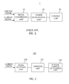
- FIG. 1 is a diagram schematically illustrating a conventional electronic watt-hour meter for detecting N-phase current.
- a conventional electronic watt-hour meter 1 for detecting N-phase current includes a signal conversion unit 10, a power measurement unit 20, and a control unit 30.
- the signal conversion unit 10 detects input three-phase analog voltage and current signals. Furthermore, the signal conversion unit 10 converts the detected analog voltage and current signals into digital signals by sequentially sampling and amplifying them, and transfers the amplified signals to the power measurement unit 20.
- the power measurement unit 20 calculates power using the voltage and current signals converted into the digital signals, and transfers the calculated power and the voltage and current signals to the control unit 30.
- the control unit 30 determines and stores transmission/reception active power, leading/lagging reactive power, a root-mean-square value during a specific period, a power factor value, or an event, such as an event regarding whether electric conduction is possible, using the voltage and current signals and the power. Furthermore, the control unit 30 calculates phases based on the calculated values of active and reactive power obtained in the same period, and calculates N-phase current using the phases.
- N-phase current should be calculated using the root-mean-square value of respective phase currents and an average phase during a specific period, a problem arises in that error range is increased and thus it is difficult to utilize a resulting value as data.
- FIG. 2 is a diagram schematically illustrating an electronic watt-hour meter for detecting N-phase current according to an embodiment of the present invention.
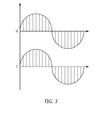
- FIG. 3 is a diagram illustrating an example of setting sampling time according to an embodiment of the present invention.
- FIG. 4 is a diagram illustrating an example of calculating an N-phase sampling current value according to an embodiment of the present invention.
- the electronic watt-hour meter 100 for detecting N-phase current may be a smart meter, and includes a signal reception unit 110, a sampling unit 120, an N-phase current calculation unit 130, and a fault detection unit 140.
- the signal reception unit 110 receives three-phase (A-phase, B-phase, and B-phase) input analog current, and transfers it to the sampling unit 120.
- the sampling unit 120 includes an A/D converter (not illustrated), and sets sampling time (hereinafter interchangeable with the "sampling interval") in order to convert the respective phase analog current into digital signals, an example of which is illustrated in FIG. 3 .
- the sampling time is set such that sampling intervals are appropriately set by considering the operation of the electronic watt-hour meter because the accuracy of the calculation of a resulting value increases in proportion to the number of sampling intervals during a unit time period but this influences operating performance, thereby consuming a large amount of power.
- the sampling unit 120 converts the respective phase analog current into digital signals based on the set sampling time.
- the N-phase current calculation unit 130 receives the respective phase sampling current values Ia, Ib and Ic (hereafter also referred to as the "sampling current value") from the sampling unit 120. Furthermore, the N-phase current calculation unit 130 adds the values at each same sampling time point among the respective phase sampling current values during a unit time period, for example, during a single period T.
- the N-phase current calculation unit 130 calculates a first N-phase sampling current value In 1 by adding a first A-phase sampling current value Ia 1 , a first B-phase sampling current value Ib 1 , and a first C-phase sampling current value Ic 1 in a superposed manner during a single period T, as illustrated in FIG. 4 .
- the number of respective-phase samplings is k during a single period T.
- the N-phase current calculation unit 130 calculates a second N-phase sampling current value In 2 by adding a second A-phase sampling current value Ia 2 , a second B-phase sampling current value Ib 2 , and a second C-phase sampling current value Ic 2 in a superposed manner.
- the N-phase current calculation unit 130 calculates a k-th N-phase sampling current value In k by adding a k-th A-phase sampling current value Ia k , a k-th B-phase sampling current value Ib k , and a k-th C-phase sampling current value Ic k in a superposed manner during a last sampling interval.
- this embodiment of the present invention is configured to calculate the N-phase current by calculating the root-mean-square value of the results obtained by adding a number of respective phase sampling current values equal to the predetermined number of samplings during a predetermined unit time period, rather than calculating phases, as in conventional art.
- N-phase current can be more simply calculated.
- the error range of the current measurement current transformer of the electronic watt-hour meter is increased twice. If, in order to mitigate the error range, a case where the load current is lower than 10% and a case where the error range is equal to or higher than 10% are identified and then N-phase current values are calculated in connection with these cases, the reliability of N-phase current data can be further improved.
- FIG. 5 is a flowchart illustrating a method of detecting N-phase current in an electronic watt-hour meter according to an embodiment of the present invention.
- the signal reception unit 110 of the electronic watt-hour meter 100 receives three-phase (A-phase, B-phase and C-phase) input analog voltage and current and transfers them to the sampling unit 120 at step S 100.
- the sampling unit 120 converts the respective phase analog voltage and current into digital signals based on set sampling time at step S110.
- the N-phase current calculation unit 130 receives respective phase sampling current values from the sampling unit 120 at step S120. Furthermore, the N-phase current calculation unit 130 calculates N-phase sampling current values In 1 , In 2 , In 3 , ..., and In k by adding the values at each same sampling time point among the respective phase sampling current values during a unit time period, for example, during a single period T, at step S 130.
- the N-phase current calculation unit 130 calculates an N-phase current value In by calculating an N-phase current root-mean-square value using the obtained N-phase sampling current values In 1 , In 2 , In 3 , ..., and In k , as described in Equation 1, at step S140.
- N-phase current is calculated by sampling input three-phase current and then calculating the root-mean-square value of results obtained by adding sampling current values at each same sampling time point during a unit time period in a superposed manner, so that zero-crossing used to calculate phases and additional processing used to correct the results of a root-mean-square value and phases can be omitted, unlike in conventional art, with the result that implementation can be made using an inexpensive metering chip and N-phase current can be faster and more accurately calculated and applied .
Landscapes
- Physics & Mathematics (AREA)
- General Physics & Mathematics (AREA)
- Engineering & Computer Science (AREA)
- Power Engineering (AREA)
- Measurement Of Current Or Voltage (AREA)
Abstract
Description
- The present invention relates to an electronic watt-hour meter for detecting N-phase current through the waveform superposition of input three-phase current and a method for detecting N-phase current using the electronic watt-hour meter and, more particularly, to an electronic watt-hour meter that samples input three-phase current and superposes the values at each same sampling time point among three-phase sampling current values during a unit time period, thereby detecting N-phase current, and a method that detects N-phase current using the electronic watt-hour meter.
- This application claims the benefit of the filing date of Korean Patent Application No.
10-2011-0097158 filed on September 26, 2011 - Conventionally, when an N-phase current value is required to detect the fault and short circuit of a three-phase electric system, N-phase current is calculated by detecting voltage and current analog signals input to a watt-hour meter, measuring power through the sequential sampling of the analog signals, calculating the root-mean-square value of respective phase currents, and obtaining phases from the calculated reactive and active power values of voltage and current during a specific period calculated using the root-mean-square value.
- However, when N-phase current is calculated as described above, N-phase current should be calculated using the root-mean-square value of respective phase currents and an average phase during a specific period (for example, 60 cycles), so that a problem arises in that error range is increased and thus it is difficult to utilize a resulting value as data.
- Meanwhile, in another method of calculating an N-phase current value, N-phase current may be calculated by calculating the root-mean-square value of respective phase currents and calculating the differences among the respective phases by using zero-crossing.
- However, these methods of calculating N-phase current are problematic in that it is difficult to use them for general purposes because they are chiefly used to calculate respective phases, rather than calculating N-phase current, and are mainly used in expensive and precise measuring instruments guaranteeing high precision.
- An object of the present invention is to provide an electronic watt-hour meter that samples input three-phase current and superposes the values at each same sampling time point among three-phase sampling current values during a unit time period, thereby detecting N-phase current, and a method that detects N-phase current using the electronic watt-hour meter.
- In order to accomplish the above object, in accordance with an embodiment of the present invention, there is provided an electronic watt-hour meter for detecting N-phase current, the electronic watt-hour meter including a sampling unit configured to calculate respective phase sampling current values by sampling input three-phase analog current; and an N-phase current calculation unit configured to receive the respective phase sampling current values, and to calculate N-phase current using results obtained by superposing the values at each same sampling time point among the respective phase sampling current values during a unit time period.
- The N-phase current calculation unit may calculate N-phase sampling current values using results obtained by adding, in a superposed manner, the values of the respective phase sampling current values at the same sampling time point during the unit time period, and may calculate the N-phase current using a result obtained by calculating the root-mean-square value of the N-phase sampling current values.
- The sampling unit may set sampling time in order to convert the input three-phase analog current into digital signals, and may calculate the respective phase sampling current values based on the set sampling time.
- In order to accomplish the above object, in accordance with an embodiment of the present invention, there is provided a method of detecting N-phase current in an electronic watt-hour meter, the method including calculating respective phase sampling current values by sampling input three-phase analog current; and calculating N-phase current by superposing the values at each same sampling time point among the respective phase sampling current values during a unit time period.
- Calculating the N-phase current may include calculating N-phase sampling current values using results obtained by adding, in a superposed manner, the values of the respective phase sampling current values at the same sampling time point during the unit time period; and calculating the N-phase current using a result obtained by calculating a root-mean-square value of the N-phase sampling current values.
- Calculating the respective phase sampling current values may include receiving the input three-phase analog current; setting sampling time in order to sample the input three-phase analog current; and calculating the respective phase sampling current values based on the set sampling time.
- In an embodiment of the present invention, N-phase current is calculated by sampling input three-phase current and then calculating the root-mean-square value of results obtained by adding sampling current values at each same sampling time point during a unit time period in a superposed manner, so that zero-crossing used to calculate phases and additional processing used to correct the results of a root-mean-square value and phases can be omitted, unlike in conventional art, with the result that implementation can be made using an inexpensive metering chip and N-phase current can be faster and more accurately calculated and applied .
-
-
FIG. 1 is a diagram schematically illustrating a conventional electronic watt-hour meter for detecting N-phase current; -
FIG. 2 is a diagram schematically illustrating an electronic watt-hour meter for detecting N-phase current according to an embodiment of the present invention; -
FIG. 3 is a diagram illustrating an example of setting sampling time according to an embodiment of the present invention; -
FIG. 4 is a diagram illustrating an example of calculating an N-phase sampling current value according to an embodiment of the present invention; and -
FIG. 5 is a flowchart illustrating a method of detecting N-phase current in an electronic watt-hour meter according to an embodiment of the present invention. - The present invention will be described in detail below with reference to the accompanying drawings. Repeated descriptions and descriptions of known functions and configurations which have been deemed to make the gist of the present invention unnecessarily obscure will be omitted below. The embodiments of the present invention are intended to fully describe the present invention to a person having ordinary knowledge in the art to which the present invention pertains. Accordingly, the shapes, sizes, etc. of components in the drawings may be exaggerated to make the description clearer.
-
FIG. 1 is a diagram schematically illustrating a conventional electronic watt-hour meter for detecting N-phase current. - As illustrated in
FIG. 1 , a conventional electronic watt-hour meter 1 for detecting N-phase current includes asignal conversion unit 10, apower measurement unit 20, and acontrol unit 30. - The
signal conversion unit 10 detects input three-phase analog voltage and current signals. Furthermore, thesignal conversion unit 10 converts the detected analog voltage and current signals into digital signals by sequentially sampling and amplifying them, and transfers the amplified signals to thepower measurement unit 20. - Then the
power measurement unit 20 calculates power using the voltage and current signals converted into the digital signals, and transfers the calculated power and the voltage and current signals to thecontrol unit 30. - The
control unit 30 determines and stores transmission/reception active power, leading/lagging reactive power, a root-mean-square value during a specific period, a power factor value, or an event, such as an event regarding whether electric conduction is possible, using the voltage and current signals and the power. Furthermore, thecontrol unit 30 calculates phases based on the calculated values of active and reactive power obtained in the same period, and calculates N-phase current using the phases. - However, since N-phase current should be calculated using the root-mean-square value of respective phase currents and an average phase during a specific period, a problem arises in that error range is increased and thus it is difficult to utilize a resulting value as data.
- An electronic watt-hour meter for detecting N-phase current according to an embodiment of the present invention, which is provided to the above problem, will be described in greater detail below with reference to
FIGS. 2 to 5 . -
FIG. 2 is a diagram schematically illustrating an electronic watt-hour meter for detecting N-phase current according to an embodiment of the present invention.FIG. 3 is a diagram illustrating an example of setting sampling time according to an embodiment of the present invention.FIG. 4 is a diagram illustrating an example of calculating an N-phase sampling current value according to an embodiment of the present invention. - As illustrated in
FIG. 2 , the electronic watt-hour meter 100 for detecting N-phase current according to this embodiment of the present invention may be a smart meter, and includes asignal reception unit 110, asampling unit 120, an N-phasecurrent calculation unit 130, and a fault detection unit 140. - The
signal reception unit 110 receives three-phase (A-phase, B-phase, and B-phase) input analog current, and transfers it to thesampling unit 120. - The
sampling unit 120 includes an A/D converter (not illustrated), and sets sampling time (hereinafter interchangeable with the "sampling interval") in order to convert the respective phase analog current into digital signals, an example of which is illustrated inFIG. 3 . In this case, the sampling time is set such that sampling intervals are appropriately set by considering the operation of the electronic watt-hour meter because the accuracy of the calculation of a resulting value increases in proportion to the number of sampling intervals during a unit time period but this influences operating performance, thereby consuming a large amount of power. Thesampling unit 120 converts the respective phase analog current into digital signals based on the set sampling time. - The N-phase
current calculation unit 130 receives the respective phase sampling current values Ia, Ib and Ic (hereafter also referred to as the "sampling current value") from thesampling unit 120. Furthermore, the N-phasecurrent calculation unit 130 adds the values at each same sampling time point among the respective phase sampling current values during a unit time period, for example, during a single period T. - More specifically, the N-phase
current calculation unit 130 calculates a first N-phase sampling current value In1 by adding a first A-phase sampling current value Ia1, a first B-phase sampling current value Ib1, and a first C-phase sampling current value Ic1 in a superposed manner during a single period T, as illustrated inFIG. 4 . In this case, it is assumed that the number of respective-phase samplings is k during a single period T. - Furthermore, the N-phase
current calculation unit 130 calculates a second N-phase sampling current value In2 by adding a second A-phase sampling current value Ia2, a second B-phase sampling current value Ib2, and a second C-phase sampling current value Ic2 in a superposed manner. - Likewise, the N-phase
current calculation unit 130 calculates a k-th N-phase sampling current value Ink by adding a k-th A-phase sampling current value Iak, a k-th B-phase sampling current value Ibk, and a k-th C-phase sampling current value Ick in a superposed manner during a last sampling interval. - Once the N-phase sampling current values In1, In2, In3, ..., and Ink have been obtained by adding the respective-phase (A-phase, B-phase and C-phase) sampling current values at each same sampling time point as described above, the N-phase
current calculation unit 130 calculates an N-phase current value In by calculating an N-phase current root-mean-square value using the obtained N-phase sampling current values In1, In2, In3, ..., and Ink, as described in Equation 1:
where In1 (Ia1+Ib1+Ic1) is the first N-phase sampling current value, In2 (Ia2+Ib2+Ic2) is the second N-phase sampling current value, ..., and Ink (Iak+Ibk+Ick) is a k-th N-phase sampling current value. - In other words, to calculate N-phase current, this embodiment of the present invention is configured to calculate the N-phase current by calculating the root-mean-square value of the results obtained by adding a number of respective phase sampling current values equal to the predetermined number of samplings during a predetermined unit time period, rather than calculating phases, as in conventional art.
- If an A/D converter for performing respective phase sampling in order to calculate N-phase current in the above-described manner can perform only sampling at the same sampling time point, N-phase current can be more simply calculated.
- Furthermore, when the load current is lower than 10% of a rated current, the error range of the current measurement current transformer of the electronic watt-hour meter is increased twice. If, in order to mitigate the error range, a case where the load current is lower than 10% and a case where the error range is equal to or higher than 10% are identified and then N-phase current values are calculated in connection with these cases, the reliability of N-phase current data can be further improved.
-
FIG. 5 is a flowchart illustrating a method of detecting N-phase current in an electronic watt-hour meter according to an embodiment of the present invention. - As illustrated in
FIG. 5 , thesignal reception unit 110 of the electronic watt-hour meter 100 according to the embodiment of the present invention receives three-phase (A-phase, B-phase and C-phase) input analog voltage and current and transfers them to thesampling unit 120 atstep S 100. - The
sampling unit 120 converts the respective phase analog voltage and current into digital signals based on set sampling time at step S110. - Then the N-phase
current calculation unit 130 receives respective phase sampling current values from thesampling unit 120 at step S120. Furthermore, the N-phasecurrent calculation unit 130 calculates N-phase sampling current values In1, In2, In3, ..., and Ink by adding the values at each same sampling time point among the respective phase sampling current values during a unit time period, for example, during a single period T, atstep S 130. - The N-phase
current calculation unit 130 calculates an N-phase current value In by calculating an N-phase current root-mean-square value using the obtained N-phase sampling current values In1, In2, In3, ..., and Ink, as described inEquation 1, at step S140. - As described above, in an embodiment of the present invention, N-phase current is calculated by sampling input three-phase current and then calculating the root-mean-square value of results obtained by adding sampling current values at each same sampling time point during a unit time period in a superposed manner, so that zero-crossing used to calculate phases and additional processing used to correct the results of a root-mean-square value and phases can be omitted, unlike in conventional art, with the result that implementation can be made using an inexpensive metering chip and N-phase current can be faster and more accurately calculated and applied .
- As described above, the optimum embodiments have been disclosed in the drawings and the specification. Although the specific terms have been used herein, they have been used merely for the purpose of describing the present invention, and have not been used to limit the meanings thereof and the scope of the present invention set forth in the claims. Therefore, it will be understood by those having ordinary knowledge in the art that various modifications and other equivalent embodiments can be made. As a result, the technical range of the protections of the present invention should be defined by the technical spirit of the attached claims.
Claims (6)
- An electronic watt-hour meter for detecting N-phase current, the electronic watt-hour meter comprising:a sampling unit configured to calculate respective phase sampling current values by sampling input three-phase analog current; andan N-phase current calculation unit configured to receive the respective phase sampling current values, and to calculate N-phase current using results obtained by superposing values at each same sampling time point among the respective phase sampling current values during a unit time period.
- The electronic watt-hour meter of claim 1, wherein the N-phase current calculation unit calculates N-phase sampling current values using results obtained by adding, in a superposed manner, the values of the respective phase sampling current values at the same sampling time point during the unit time period, and calculates the N-phase current using a result obtained by calculating a root-mean-square value of the N-phase sampling current values.
- The electronic watt-hour meter of claim 1, wherein the sampling unit sets sampling time in order to convert the input three-phase analog current into digital signals, and calculates the respective phase sampling current values based on the set sampling time.
- A method of detecting N-phase current in an electronic watt-hour meter, the method comprising:calculating respective phase sampling current values by sampling input three-phase analog current; andcalculating N-phase current by superposing values at each same sampling time point among the respective phase sampling current values during a unit time period.
- The method of claim 4, wherein calculating the N-phase current comprises:calculating N-phase sampling current values using results obtained by adding, in a superposed manner, the values of the respective phase sampling current values at the same sampling time point during the unit time period; andcalculating the N-phase current using a result obtained by calculating a root-mean-square value of the N-phase sampling current values.
- The method of claim 4, wherein calculating the respective phase sampling current values comprises:receiving the input three-phase analog current;setting sampling time in order to sample the input three-phase analog current; andcalculating the respective phase sampling current values based on the set sampling time.
Applications Claiming Priority (2)
| Application Number | Priority Date | Filing Date | Title |
|---|---|---|---|
| KR20110097158A KR20130033212A (en) | 2011-09-26 | 2011-09-26 | Electronic watt-hour meter for detecting n phase current by waveform superposition of 3 phase input current and method for detecting using thereof |
| PCT/KR2011/007739 WO2013047940A1 (en) | 2011-09-26 | 2011-10-18 | Electronic power meter for detecting an n phase current based on waveform superposition of a three phase input current, and n phase current detecting method using same |
Publications (2)
| Publication Number | Publication Date |
|---|---|
| EP2762904A1 true EP2762904A1 (en) | 2014-08-06 |
| EP2762904A4 EP2762904A4 (en) | 2015-10-28 |
Family
ID=47995947
Family Applications (1)
| Application Number | Title | Priority Date | Filing Date |
|---|---|---|---|
| EP11873445.8A Withdrawn EP2762904A4 (en) | 2011-09-26 | 2011-10-18 | ELECTRONIC WATTMETER FOR N-PHASE CURRENT DETECTION BASED ON SUPERPOSITION OF THREE-PHASE INPUT CURRENT WAVEFORMS AND METHOD OF DETECTING N-PHASE CURRENT USING THE SAME |
Country Status (3)
| Country | Link |
|---|---|
| EP (1) | EP2762904A4 (en) |
| KR (1) | KR20130033212A (en) |
| WO (1) | WO2013047940A1 (en) |
Family Cites Families (9)
| Publication number | Priority date | Publication date | Assignee | Title |
|---|---|---|---|---|
| US4217545A (en) * | 1975-06-20 | 1980-08-12 | Nihon Denki Keiki Kenteisho | Electronic type polyphase electric energy meter |
| US5245275A (en) * | 1989-09-25 | 1993-09-14 | General Electric Company | Electronic watthour meter |
| US5406495A (en) * | 1993-02-01 | 1995-04-11 | Systems Analysis And Integration, Inc. | Substation load distribution monitor system |
| US5627718A (en) * | 1994-11-18 | 1997-05-06 | Eaton Corporation | Apparatus providing protection and metering in an ac electrical system utilizing a multi-function sampling technique |
| US5673196A (en) * | 1995-11-30 | 1997-09-30 | General Electric Company | Vector electricity meters and associated vector electricity metering methods |
| JP3491676B2 (en) * | 1999-05-21 | 2004-01-26 | 横河電機株式会社 | Measuring instrument for three-phase AC |
| KR100666504B1 (en) * | 2004-07-16 | 2007-01-09 | 엘에스산전 주식회사 | Apparatus and method for fault identification and error compensation of current sensor in vector inverter system |
| KR200397632Y1 (en) * | 2005-06-22 | 2005-10-06 | 임택재 | n-phase power harmonics detection shape watt hour meter |
| KR101133234B1 (en) * | 2010-01-22 | 2012-04-05 | 한전케이피에스 주식회사 | Resolution increase method of device defect signal by synthesizing of electric motor 3 phase current signal |
-
2011
- 2011-09-26 KR KR20110097158A patent/KR20130033212A/en not_active Ceased
- 2011-10-18 EP EP11873445.8A patent/EP2762904A4/en not_active Withdrawn
- 2011-10-18 WO PCT/KR2011/007739 patent/WO2013047940A1/en not_active Ceased
Also Published As
| Publication number | Publication date |
|---|---|
| WO2013047940A1 (en) | 2013-04-04 |
| KR20130033212A (en) | 2013-04-03 |
| EP2762904A4 (en) | 2015-10-28 |
Similar Documents
| Publication | Publication Date | Title |
|---|---|---|
| US8655608B2 (en) | Symmetrical component amplitude and phase comparators for line protection using time stamped data | |
| US8108165B2 (en) | Acquiring phasors outside the frequency tracking range for power protective relays | |
| US20140062457A1 (en) | Three-phase ac phase sequence detecting method and apparatus | |
| US8145443B2 (en) | Fourier transform-based phasor estimation method and apparatus capable of eliminating influence of exponentially decaying DC offsets | |
| US9128140B2 (en) | Detection of a fault in an ungrounded electric power distribution system | |
| CN104122439B (en) | Electric energy meter capable of improving phase correction precision | |
| WO2013181809A1 (en) | Method for identifying fault by current differential protection and device thereof | |
| CN104155517B (en) | A kind of non-integer-period sampled error compensating method of digitalized electrical energy meter and system | |
| EP2397864A1 (en) | Electricity meter and method for determining a quantity | |
| Petrovic | New digital multimeter for accurate measurement of synchronously sampled AC signals | |
| CN106842097A (en) | A kind of anti-DC performance detection means of current transformer and method | |
| EP3312621A1 (en) | Leak current detecting device | |
| US20020033694A1 (en) | Method to determine fundamental and harmonic oscillations of a measured electrical quantity | |
| US9194897B2 (en) | Electronic watt-hour meter and electronic watt-hour measuring method | |
| EP2490031A1 (en) | Method and system for measuring an electrical quantity in an electrical network | |
| EP3093624B1 (en) | Self-calibrating lvdt transformer demodulator | |
| JP2008003055A (en) | Energy meter adjustment device and energy meter | |
| CN114167135B (en) | Voltage-current phase angle distinguishing method for power meter | |
| EP2762904A1 (en) | Electronic power meter for detecting an n phase current based on waveform superposition of a three phase input current, and n phase current detecting method using same | |
| US9863986B2 (en) | Electric power measuring system | |
| WO2008016274A1 (en) | Measuring instrument for an electric current leakage | |
| KR100824515B1 (en) | Digital power system measuring device and method | |
| JP2008032633A (en) | Insulation monitoring apparatus and method for electrical equipment | |
| CN103176030A (en) | Method for detecting inter-harmonics of power distribution system | |
| JP2008154362A (en) | Power system state estimation apparatus and method |
Legal Events
| Date | Code | Title | Description |
|---|---|---|---|
| PUAI | Public reference made under article 153(3) epc to a published international application that has entered the european phase |
Free format text: ORIGINAL CODE: 0009012 |
|
| 17P | Request for examination filed |
Effective date: 20140326 |
|
| AK | Designated contracting states |
Kind code of ref document: A1 Designated state(s): AL AT BE BG CH CY CZ DE DK EE ES FI FR GB GR HR HU IE IS IT LI LT LU LV MC MK MT NL NO PL PT RO RS SE SI SK SM TR |
|
| DAX | Request for extension of the european patent (deleted) | ||
| RA4 | Supplementary search report drawn up and despatched (corrected) |
Effective date: 20150925 |
|
| RIC1 | Information provided on ipc code assigned before grant |
Ipc: G01R 22/06 20060101AFI20150921BHEP |
|
| 17Q | First examination report despatched |
Effective date: 20180417 |
|
| STAA | Information on the status of an ep patent application or granted ep patent |
Free format text: STATUS: THE APPLICATION IS DEEMED TO BE WITHDRAWN |
|
| 18D | Application deemed to be withdrawn |
Effective date: 20180828 |