EP2762834A1 - An integrated global navigation satellite system and inertial navigation system - Google Patents
An integrated global navigation satellite system and inertial navigation system Download PDFInfo
- Publication number
- EP2762834A1 EP2762834A1 EP13153646.8A EP13153646A EP2762834A1 EP 2762834 A1 EP2762834 A1 EP 2762834A1 EP 13153646 A EP13153646 A EP 13153646A EP 2762834 A1 EP2762834 A1 EP 2762834A1
- Authority
- EP
- European Patent Office
- Prior art keywords
- spectrum density
- power spectrum
- frequency band
- low frequency
- navigation
- Prior art date
- Legal status (The legal status is an assumption and is not a legal conclusion. Google has not performed a legal analysis and makes no representation as to the accuracy of the status listed.)
- Granted
Links
Images



Classifications
-
- G—PHYSICS
- G01—MEASURING; TESTING
- G01P—MEASURING LINEAR OR ANGULAR SPEED, ACCELERATION, DECELERATION, OR SHOCK; INDICATING PRESENCE, ABSENCE, OR DIRECTION, OF MOVEMENT
- G01P15/00—Measuring acceleration; Measuring deceleration; Measuring shock, i.e. sudden change of acceleration
- G01P15/14—Measuring acceleration; Measuring deceleration; Measuring shock, i.e. sudden change of acceleration by making use of gyroscopes
-
- G—PHYSICS
- G01—MEASURING; TESTING
- G01C—MEASURING DISTANCES, LEVELS OR BEARINGS; SURVEYING; NAVIGATION; GYROSCOPIC INSTRUMENTS; PHOTOGRAMMETRY OR VIDEOGRAMMETRY
- G01C21/00—Navigation; Navigational instruments not provided for in groups G01C1/00 - G01C19/00
- G01C21/20—Instruments for performing navigational calculations
-
- G—PHYSICS
- G01—MEASURING; TESTING
- G01C—MEASURING DISTANCES, LEVELS OR BEARINGS; SURVEYING; NAVIGATION; GYROSCOPIC INSTRUMENTS; PHOTOGRAMMETRY OR VIDEOGRAMMETRY
- G01C21/00—Navigation; Navigational instruments not provided for in groups G01C1/00 - G01C19/00
- G01C21/20—Instruments for performing navigational calculations
- G01C21/206—Instruments for performing navigational calculations specially adapted for indoor navigation
-
- G—PHYSICS
- G01—MEASURING; TESTING
- G01C—MEASURING DISTANCES, LEVELS OR BEARINGS; SURVEYING; NAVIGATION; GYROSCOPIC INSTRUMENTS; PHOTOGRAMMETRY OR VIDEOGRAMMETRY
- G01C22/00—Measuring distance traversed on the ground by vehicles, persons, animals or other moving solid bodies, e.g. using odometers, using pedometers
- G01C22/006—Pedometers
-
- G—PHYSICS
- G01—MEASURING; TESTING
- G01P—MEASURING LINEAR OR ANGULAR SPEED, ACCELERATION, DECELERATION, OR SHOCK; INDICATING PRESENCE, ABSENCE, OR DIRECTION, OF MOVEMENT
- G01P15/00—Measuring acceleration; Measuring deceleration; Measuring shock, i.e. sudden change of acceleration
Definitions
- the present invention concerns the implementation of an integrated global navigation satellite system and inertial navigation systems in a portable mobile device having at least a pedestrian navigation mode and a road vehicle navigation mode.
- the system addresses a problem of navigation mode selection at pedestrian speeds.
- GNSS Global navigation satellite systems
- the modes of travel are (1) pedestrian or (2) road.
- pedestrian mode means travel on foot or vehicle (such as a wheel chair) in an essentially pedestrian area such as a footpath (sidewalk).
- Road mode is via a vehicle such as an automobile, truck, motorcycle or push bike on a road intended for vehicular traffic. It is important for a navigation device to distinguish between the modes in order to select appropriate guidance to a user. While many devices already provide means for the user to make a selection, it is not unusual for the user to forget to make the mode switch.
- GNSS devices rely on a receiver which receives a signal from each of at least four GPS satellites to locate the instantaneous position of the device.
- Each satellite signal carries a time signal which allows the receiver device to calculate the transit time from the signal transmission to reception assuming that each signal travels in a straight line. From this, the device can calculate its position with an accuracy of the order of tens of meters and often much better. Accuracy depends on a number of factors including the quality of the device but is generally very dependent on the number of satellites which are simultaneously visible to the device.
- GNSS devices commonly correlate the position with coordinates on a map contained within a memory and use this information to provide guidance information to the user in the form of audible and/or visible instructions to follow a path to a destination.
- GNSS cannot directly determine the orientation and speed of the device and hence the user. Speed and orientation are only determined by inference from changes in position over time. It is essential that the device infer the correct orientation and speed in order for the device to provide accurate appropriately timed instructions.
- GNSS Global System for Mobile Communications
- WO2008/148794 provides an example of the use of an accelerometer inertial sensor to correct for multipath error in a GNSS. This system senses events where reception of a multi-path signal indicates that the GNSS device has moved between two points which are incompatible with the signal from the inertial sensor in the same time period.
- a GNSS system switches between pedestrian mode and road mode in response to the speed of the device.
- traffic congestion results in vehicle road speeds similar to pedestrian speeds which can result in an incorrect mode selection by the device.
- US2011/202754 distinguishes between a pedestrian mode and road mode by reference to signals from an inertial sensor such as an accelerometer.
- the system of US2011/202754 correlates the fluctuations of an accelerometer signal with the expected fluctuations in acceleration arising from a walking or running person and indicates a pedestrian mode if the correlation is high and other factors such as a speed threshold are not exceeded.
- Road mode is determined by the speed of the vehicle exceeding a threshold and the GNSS device being positioned on the road. It will be appreciated that this system remains susceptible to incorrect mode selection where low road speeds and incorrect map snapping to a pedestrian area occur due to multi-path signal reception.
- a GNSS device especially one embedded in a cell-phone may be handled by a user in a manner which generates signals indicative of abrupt changes of direction compatible with a pedestrian mode.
- the GNSS device may switch to pedestrian mode and calculate the route to destination accordingly although the device is travelling in a vehicle.
- the present invention aims to alleviate at least some of the technical limitations of the prior art by the provision of a portable mobile device having a navigation system comprising:
- the present invention comprises a navigation process implemented in a portable mobile device comprising the steps of:
- code adapted for communication via large area network, WiFi, cell phone network or recorded on physical media for execution in a processor in a portable device to implement the process according to the second aspect of the present invention recited above.
- the present invention relies on the discovery that the frequency of excitations of an inertial sensor carried by a pedestrian, including stationary manipulations of the device, occur typically at a frequency of less than ten hertz, and usually well below ten hertz.
- An inertial sensor conveyed in a device travelling in a vehicle in road mode senses excitations at a frequency typically below twenty five hertz.
- Such road mode inertial excitations are typically induced by vehicle engine motion, road condition, air-conditioning activity, windscreen wiper activity.
- a predominance of excitations in a low frequency band, corresponding to the pedestrian mode will indicate pedestrian mode navigation.
- a predominance of excitations in a high frequency band is indicative of road mode navigation.
- the comparator outputs a signal indicative of pedestrian mode navigation when the low frequency band power spectrum density exceeds the high frequency band power spectrum density. Conversely the comparator outputs a signal indicative of road mode navigation when the high frequency band power spectrum density exceeds the low frequency band power spectrum density.
- dominance may be determined by more complex criteria, to address a condition where each band signal strength is low or there is not much difference. In this condition the dominant frequency band power spectrum density may not be the highest frequency band power spectrum density.
- the low frequency band is between two and ten hertz and the high frequency band is between ten and twenty five hertz.
- the invention also contemplates the possibility of a condition where the power spectrum densities of each of the low and high frequency bands are both strongly present.
- This condition may occur where a vehicle passenger or driver is manipulating the device in a slow, or erratically moving vehicle or a vehicle stationary in traffic.
- the difference between the low frequency power spectrum density and the high frequency power spectrum density may be small.
- the dominant power spectrum density may change frequently. Consequently, the mode signal output from the comparator may change frequently over a short time leading to frequent and confusing changes in navigation mode.
- the system and process is set so that the comparison of the power spectrum densities may only occur if the low band power spectrum density exceeds a predetermined threshold value.
- the step of comparing may conveniently comprise the calculation of a power spectrum density ratio of the low band power spectrum density and the high band power spectrum density.
- the system will preferably determine pedestrian mode where:
- the higher power spectrum density threshold ratio is between 1 and 2, and more preferably 1.5.
- the second low band power spectrum density threshold is at least 1.5 times the size of the first low band power spectrum density threshold and more preferably twice the size of the first low band power spectrum density threshold.
- the lower power spectrum density threshold ratio is between 0.5 and 1 and more preferably 0.75.
- Conditions (a) and (b) indicate that the pedestrian is walking.
- Conditions (c) and (d) indicate that the pedestrian is running.
- a delay timer may be provided to delay cancellation of the pedestrian mode, and consequent switching to the road mode.
- the delay timer may be implemented when the low frequency band power spectrum density falls briefly below a large fraction of the first low frequency band power spectrum density threshold, but continues to exceed the high frequency band power spectrum density. The large fraction may be 80% of the threshold at (a).
- the timer may be provided by a countdown timer which may count down from a preset timer value which may be 512.
- the counter may be decremented by one for each sequential cycle of the process that the low band power spectrum density remains at less than 80% of the threshold value.
- the timer may be reset, preferably by resetting the countdown timer to its initial value, for example 512.
- the present invention provides a means of distinguishing between pedestrian and road navigation modes where simple speed or position and map snapping are unreliable.
- the device and process may distinguish between the user manipulating a device while walking and the user manipulating the device while in a car.
- the device and process may distinguish between distinguish between a pedestrian carrying and manipulating the device while walking at low speed and a device fixed in a road vehicle travelling at low speed or stationary in congested traffic.
- the load on the device processor imposed by the execution of the process is constant.
- Figure 1 shows a device in the form of a cell phone 1 while executing a global navigation satellite application resulting in the display of a relevant map 2 on a touch screen 3.
- the cell phone incorporates a processor 3A arranged to process data supplied from the touch screen 3 or received from an antenna 4 in accordance with instructions executing from machine readable code recorded in a memory 3B.
- the cell phone 1 may interface with the user via the touch screen to receive instructions and to display the instant location of the cell phone and a route to a destination to which the user wishes to navigate.
- the route may include roads from which pedestrians are excluded and footpaths from which vehicular traffic is excluded. To optimise the route it is therefore important that the cell phone 1 selects the route for navigation in accordance with the mode of travel, in this case the modes are pedestrian or road modes.
- the cell phone 1 includes a global positioning system (GPS) antenna 4 able to receive global positioning system radio GPS signals from satellites in known fashion.
- GPS global positioning system
- GNSS global navigation satellite subsystem
- An inertial sensor in the form of an accelerometer 6 is included in cell phone 1 which is sensitive to accelerations of the cell phone 1.
- signals from the inertial sensor are processed by an inertial navigation subsystem 7 and used to calculate the speed and heading of the cell phone at step S2. If the speed calculated from the inertial sensor is incompatible with a pedestrian speed for example a speed in excess of 21 km/h, the cell phone implements a road navigation mode in GNSS 5. However, if the speed calculated at step S2 is a possible pedestrian speed the process implements a navigation mode discrimination routine at step S3.
- the mode discrimination routine samples the frequency of excitations of the inertial sensor 6 at sampler 8 and step S4 and filters sample through low band pass filter 9 and high band pass filter 10 at steps S5 and S6 respectively.
- the low band pass filter filters signals between 2Hz and 10Hz while the high band pass filter filters between 10 Hz and 25 Hz.
- the low band signal is supplied to a low frequency band calculator 11 which calculates the low frequency band power spectrum density (PSD1) at step S7.
- the high frequency band signal is used by calculator 12 at step S8 to calculate a high frequency band power spectrum density (PSD2).
- a calculator calculates the ratio of the low frequency power spectrum density (PSD1) to the high frequency power spectrum density (PSD2) to generate the power spectrum density ratio (PSDR).
- the calculator may generate a navigation mode selection signal based solely on whether or not the PSDR is greater than or less than one. If the PSDR is greater than one, the low frequency excitations are dominant and the pedestrian mode should be selected. If the PSDR is less than one, the high frequency excitations are dominant and the road navigation mode is selected.
- this simple variant does not deal well with situations where each signal is weak or the power spectrum densities are close in value.
- step S10 the low frequency band power spectrum density is compared with a first threshold. If the low frequency power spectrum density is less than the first threshold value, the process generates a navigation mode selection signal causing selection of the road mode for navigation.
- step S10 the low frequency band power spectrum density exceeds the first threshold
- step S11 the low frequency band power spectrum density is compared to a second threshold, which in this case is the double threshold at step S11.
- the term "double threshold” is used to indicate the value of the first threshold multiplied by a factor 2.
- the power spectrum density ratio is compared to a high spectrum density ratio threshold in step S12.
- the high spectrum density ratio threshold is 1.5 times the value of the first threshold to determine if the low frequency excitations are dominant.
- the system and process determines that the device is being carried by a pedestrian.
- the pedestrian mode selection signal is generated accordingly and the GNSS subsystem responds to implement a pedestrian navigation mode at step S13.
- step 14 compares the power spectrum density ratio to a lower power spectrum density threshold ratio.
- the lower power spectrum density ratio threshold is 0.75. If the lower power spectrum density ratio threshold is not exceeded the process goes to step S14 where a road mode selection signal is generated and the GNSS responds to implement road navigation. If the lower power spectrum density ratio threshold is exceeded the process causes the system to generate a pedestrian mode selection signal which causes the GNSS subsystem to implement the pedestrian navigation mode at step S13.
- Figure 4 is a chart of an inertial sensor excitation sample taken during a combined pedestrian and road navigation with time plotted on the X axis increasing from left to right and the excitations in low and high frequency bands plotted on the Y axis.
- the blue line is the low frequency band sample while the red line indicates the high frequency band sample.
- Figure 5 shows the power spectrum density plotted on the Y axis with time on the X axis. The scaling is slightly different for each graph however the correlation between the transport modes is readily apparent.
- the cell phone In the first period P1 the cell phone is lying on a desk and is immobile. Little or no excitation of either low or high frequency band is detected.
- the cell phone 1 is carried to the car by a walking user.
- the power spectrum density of the low frequency band greatly exceeds the high frequency band power spectrum density indicative of pedestrian travel, if GNSS navigation was activated, pedestrian mode would readily be identified and selected by the process.
- the user fixes the cell phone into a dashboard mounting.
- the recording shows each of low and high frequency excitations in relatively similar amounts as the cell phone is manipulated.
- the criteria at step S10 requiring the low frequency power spectrum density to exceed a minimum threshold to stop pedestrian mode selection results in road mode selection although the high frequency power spectrum density is lower than the low frequency power spectrum density in the third period.
- the vehicle engine is started and the vehicle driven away.
- the high frequency power spectrum density rises quickly to greatly exceed the low frequency power spectrum density ensuring that at any speed, road mode navigation is selected.
- road mode navigation frequent rapid changes of heading are blocked in the GNSS.
- the cell phone is handled by the user picking up a cell phone call.
- this results in considerable excitation in the high frequency band which can include rapid changes of direction unconnected with the overall motion of the vehicle.
- the high frequency power spectrum density remains dominant in figure 5 and no change of navigation mode will occur.
- maintenance of the road navigation mode blocks rapid changes in heading in the GNSS.
- the sixth period P6 is substantially similar to the fourth period of driving.
- the vehicle comes to a halt at a fuel station and the user exits the vehicle during eighth period P8 and undertakes pedestrian activities.
- the low frequency power spectrum density is clearly dominant over the high frequency power spectrum density and the cell phone would switch to pedestrian mode navigation.
- the ninth period P9 activity is essentially similar to the third period P3 as the user returns to the vehicle, remounts the cell phone and drives away at period P10.
- the driver stops the vehicle removes the cell phone from the mount and walks away.
- the low frequency power spectrum density rises to dominate the high frequency power spectrum density and the cell phone switches to pedestrian navigation mode.
- cell phones, personal digital assistants and dedicated man portable global navigation satellite system devices commonly incorporate an inertial sensor and can therefore be adapted to implement the components and process described above by loading and/or updating code to execute in a processor of the device.
- the code to implement the process may be loaded onto device memory via a USB port, bluetooth, WiFi, GSM or other compatible technologies for recordal in a device memory and execution on the device processor.
Landscapes
- Engineering & Computer Science (AREA)
- Radar, Positioning & Navigation (AREA)
- Remote Sensing (AREA)
- Physics & Mathematics (AREA)
- General Physics & Mathematics (AREA)
- Automation & Control Theory (AREA)
- Navigation (AREA)
- Electric Propulsion And Braking For Vehicles (AREA)
- Control Of Driving Devices And Active Controlling Of Vehicle (AREA)
- Traffic Control Systems (AREA)
Abstract
Description
- The present invention concerns the implementation of an integrated global navigation satellite system and inertial navigation systems in a portable mobile device having at least a pedestrian navigation mode and a road vehicle navigation mode. In particular the system addresses a problem of navigation mode selection at pedestrian speeds.
- Global navigation satellite systems (GNSS) are used in numerous devices to calculate an instantaneous global position of the device, on or above the Earth's surface or at sea. GNSS uses the position to direct the user or a robot vehicle toward a programmed destination via a route appropriate to a mode of travel. For the purpose of the present invention the modes of travel are (1) pedestrian or (2) road. For these purposes pedestrian mode means travel on foot or vehicle (such as a wheel chair) in an essentially pedestrian area such as a footpath (sidewalk). Road mode is via a vehicle such as an automobile, truck, motorcycle or push bike on a road intended for vehicular traffic. It is important for a navigation device to distinguish between the modes in order to select appropriate guidance to a user. While many devices already provide means for the user to make a selection, it is not unusual for the user to forget to make the mode switch.
- GNSS devices rely on a receiver which receives a signal from each of at least four GPS satellites to locate the instantaneous position of the device. Each satellite signal carries a time signal which allows the receiver device to calculate the transit time from the signal transmission to reception assuming that each signal travels in a straight line. From this, the device can calculate its position with an accuracy of the order of tens of meters and often much better. Accuracy depends on a number of factors including the quality of the device but is generally very dependent on the number of satellites which are simultaneously visible to the device.
- GNSS devices commonly correlate the position with coordinates on a map contained within a memory and use this information to provide guidance information to the user in the form of audible and/or visible instructions to follow a path to a destination. GNSS cannot directly determine the orientation and speed of the device and hence the user. Speed and orientation are only determined by inference from changes in position over time. It is essential that the device infer the correct orientation and speed in order for the device to provide accurate appropriately timed instructions.
- One factor which leads to errors of position in GNSS is a situation which leads to one or more satellite signals travelling over a non-linear path to the GNSS device receiver. This can occur in canyon-like environments where a satellite signal is reflected from nearby structures, such as buildings, before reaching the device receiver. Because this leads to errors of position, multi-pathing also leads to errors of heading and speed. When the GNSS incorrectly positions the GNSS device on the map (map snapping) it will provide false guidance, potentially by setting a false navigation mode.
-
WO2008/148794 provides an example of the use of an accelerometer inertial sensor to correct for multipath error in a GNSS. This system senses events where reception of a multi-path signal indicates that the GNSS device has moved between two points which are incompatible with the signal from the inertial sensor in the same time period. - In some cases such as
US2010/114477 a GNSS system switches between pedestrian mode and road mode in response to the speed of the device. However, especially in urban environments, traffic congestion results in vehicle road speeds similar to pedestrian speeds which can result in an incorrect mode selection by the device. - When the GNSS device is carried by a pedestrian in a pedestrian mode the pedestrian can and often does change direction rapidly and frequently, for example to avoid other pedestrians and obstacles along the path of navigation. In the road mode the device will move with the vehicle. The vehicle cannot change direction with the abruptness of a pedestrian and will be constrained to navigate the road.
US2011/202754 distinguishes between a pedestrian mode and road mode by reference to signals from an inertial sensor such as an accelerometer. The system ofUS2011/202754 correlates the fluctuations of an accelerometer signal with the expected fluctuations in acceleration arising from a walking or running person and indicates a pedestrian mode if the correlation is high and other factors such as a speed threshold are not exceeded. Road mode is determined by the speed of the vehicle exceeding a threshold and the GNSS device being positioned on the road. It will be appreciated that this system remains susceptible to incorrect mode selection where low road speeds and incorrect map snapping to a pedestrian area occur due to multi-path signal reception. - In the road mode a GNSS device, especially one embedded in a cell-phone may be handled by a user in a manner which generates signals indicative of abrupt changes of direction compatible with a pedestrian mode. In such situations the GNSS device may switch to pedestrian mode and calculate the route to destination accordingly although the device is travelling in a vehicle.
- Accordingly, the present invention aims to alleviate at least some of the technical limitations of the prior art by the provision of a portable mobile device having a navigation system comprising:
- a global navigation satellite subsystem, an inertial navigation subsystem, an inertial sensor and a processor;
- the processor being responsive to signals output by said global navigation satellite subsystem and the inertial navigation subsystem to implement a navigation mode discrimination routine for selecting one of a pedestrian navigation mode or a road navigation mode;
- characterized in that said mode discrimination comprises a sampler to sample the frequency of excitations of the inertial sensor, a low band filter and a high band filter to filter the frequency sample to a low frequency band sample and a high frequency band sample,
- a calculator module responsive to each of said low frequency band sample and said high frequency band sample to calculate a low band power spectrum density and a high band power spectrum density,
- a comparator able to compare the low band power spectrum density and the high band power spectrum density and to generate a mode selection signal; and
- the global navigation satellite subsystem adapted to respond to the mode selection signal to select one of the navigation modes. By the term "portable" it is meant a man portable device and by the term "communication device" we refer to any device comprising an antenna.
- In a second aspect, the present invention comprises a navigation process implemented in a portable mobile device comprising the steps of:
- executing a global navigation satellite routine and an inertial navigation routine, said inertial navigation routine being responsive to signals output from an inertial sensor,
- sampling the frequency of excitations of the inertial sensor,
- filtering the frequency sample to a low frequency band and a high frequency band:
- calculating the power spectrum density of the low frequency band and the high frequency band;
- comparing the power spectrum density of the low frequency band and the high frequency band and;
- selecting a navigation mode according to the comparison of the power spectrum density of the low frequency band and the high frequency band.
- According to a third aspect of the present invention there is provided code adapted for communication via large area network, WiFi, cell phone network or recorded on physical media for execution in a processor in a portable device to implement the process according to the second aspect of the present invention recited above.
- The present invention relies on the discovery that the frequency of excitations of an inertial sensor carried by a pedestrian, including stationary manipulations of the device, occur typically at a frequency of less than ten hertz, and usually well below ten hertz. An inertial sensor conveyed in a device travelling in a vehicle in road mode senses excitations at a frequency typically below twenty five hertz. Such road mode inertial excitations are typically induced by vehicle engine motion, road condition, air-conditioning activity, windscreen wiper activity. Evidently from this, a predominance of excitations in a low frequency band, corresponding to the pedestrian mode, will indicate pedestrian mode navigation. Conversely a predominance of excitations in a high frequency band is indicative of road mode navigation. In general, the comparator outputs a signal indicative of pedestrian mode navigation when the low frequency band power spectrum density exceeds the high frequency band power spectrum density. Conversely the comparator outputs a signal indicative of road mode navigation when the high frequency band power spectrum density exceeds the low frequency band power spectrum density. However, as explained more detailed later, dominance may be determined by more complex criteria, to address a condition where each band signal strength is low or there is not much difference. In this condition the dominant frequency band power spectrum density may not be the highest frequency band power spectrum density.
- Preferably the low frequency band is between two and ten hertz and the high frequency band is between ten and twenty five hertz.
- The invention also contemplates the possibility of a condition where the power spectrum densities of each of the low and high frequency bands are both strongly present. This condition may occur where a vehicle passenger or driver is manipulating the device in a slow, or erratically moving vehicle or a vehicle stationary in traffic. In this condition the difference between the low frequency power spectrum density and the high frequency power spectrum density may be small. The dominant power spectrum density may change frequently. Consequently, the mode signal output from the comparator may change frequently over a short time leading to frequent and confusing changes in navigation mode. To avoid this problem the system and process is set so that the comparison of the power spectrum densities may only occur if the low band power spectrum density exceeds a predetermined threshold value.
- The step of comparing may conveniently comprise the calculation of a power spectrum density ratio of the low band power spectrum density and the high band power spectrum density. The system will preferably determine pedestrian mode where:
- a. the low band power density spectrum exceeds a first low band power density spectrum threshold and
- b. if the power spectrum density ratio exceeds a higher power spectrum density threshold ratio; or
- c. the low band power density spectrum exceeds a second low band power spectrum density threshold, higher than the first low band power spectrum density threshold and
- d. the power spectrum density ratio exceeds a lower power spectrum density threshold ratio.
- Preferably the higher power spectrum density threshold ratio is between 1 and 2, and more preferably 1.5. Preferably the second low band power spectrum density threshold is at least 1.5 times the size of the first low band power spectrum density threshold and more preferably twice the size of the first low band power spectrum density threshold. Preferably the lower power spectrum density threshold ratio is between 0.5 and 1 and more preferably 0.75.
- Conditions (a) and (b) indicate that the pedestrian is walking. Conditions (c) and (d) indicate that the pedestrian is running.
- Under the conditions expressed in the immediately preceding paragraph the navigation mode may be instantly switched. However, a delay timer may be provided to delay cancellation of the pedestrian mode, and consequent switching to the road mode. The delay timer may be implemented when the low frequency band power spectrum density falls briefly below a large fraction of the first low frequency band power spectrum density threshold, but continues to exceed the high frequency band power spectrum density. The large fraction may be 80% of the threshold at (a). The timer may be provided by a countdown timer which may count down from a preset timer value which may be 512. The counter may be decremented by one for each sequential cycle of the process that the low band power spectrum density remains at less than 80% of the threshold value. When the threshold power density spectrum value is exceeded the timer may be reset, preferably by resetting the countdown timer to its initial value, for example 512.
- The present invention provides a means of distinguishing between pedestrian and road navigation modes where simple speed or position and map snapping are unreliable. The device and process may distinguish between the user manipulating a device while walking and the user manipulating the device while in a car. The device and process may distinguish between distinguish between a pedestrian carrying and manipulating the device while walking at low speed and a device fixed in a road vehicle travelling at low speed or stationary in congested traffic. The load on the device processor imposed by the execution of the process is constant.
- A device and process embodying the present invention will now be described, by way of example only, with reference to the accompanying illustrative drawings,
wherein: -
figure 1 illustrates a device in the form of a cellphone; -
figure 1A is a simplified diagram of the main cell phone components; -
figure 2 is a diagrammatic view of the components of the device; -
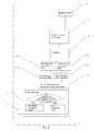
figure 3 is a flow chart of the process implemented by the device; -
figure 4 is a chart characteristic of the low and high frequency band excitation of the inertial sensor for a journey comprising a mixed sequence of pedestrian and road travel; and -
figure 5 is a chart of the low and high frequency band power spectrum densities of the journey sample infigure 4 . -
Figure 1 shows a device in the form of acell phone 1 while executing a global navigation satellite application resulting in the display of arelevant map 2 on atouch screen 3. As is diagrammatically illustrated infigure 1A the cell phone incorporates aprocessor 3A arranged to process data supplied from thetouch screen 3 or received from anantenna 4 in accordance with instructions executing from machine readable code recorded in amemory 3B. As is well known, thecell phone 1 may interface with the user via the touch screen to receive instructions and to display the instant location of the cell phone and a route to a destination to which the user wishes to navigate. The route may include roads from which pedestrians are excluded and footpaths from which vehicular traffic is excluded. To optimise the route it is therefore important that thecell phone 1 selects the route for navigation in accordance with the mode of travel, in this case the modes are pedestrian or road modes. - As shown diagrammatically in
figure 2 thecell phone 1 includes a global positioning system (GPS)antenna 4 able to receive global positioning system radio GPS signals from satellites in known fashion. The GPS signals are delivered to a global navigation satellite subsystem (GNSS) 5. - An inertial sensor in the form of an
accelerometer 6 is included incell phone 1 which is sensitive to accelerations of thecell phone 1. When the GNSS is initiated as at step S1, signals from the inertial sensor are processed by aninertial navigation subsystem 7 and used to calculate the speed and heading of the cell phone at step S2. If the speed calculated from the inertial sensor is incompatible with a pedestrian speed for example a speed in excess of 21 km/h, the cell phone implements a road navigation mode inGNSS 5. However, if the speed calculated at step S2 is a possible pedestrian speed the process implements a navigation mode discrimination routine at step S3. - The mode discrimination routine samples the frequency of excitations of the
inertial sensor 6 at sampler 8 and step S4 and filters sample through lowband pass filter 9 and highband pass filter 10 at steps S5 and S6 respectively. The low band pass filter filters signals between 2Hz and 10Hz while the high band pass filter filters between 10 Hz and 25 Hz. The low band signal is supplied to a lowfrequency band calculator 11 which calculates the low frequency band power spectrum density (PSD1) at step S7. - The high frequency band signal is used by
calculator 12 at step S8 to calculate a high frequency band power spectrum density (PSD2). At step S9 a calculator calculates the ratio of the low frequency power spectrum density (PSD1) to the high frequency power spectrum density (PSD2) to generate the power spectrum density ratio (PSDR). In the simplest variant of the invention the calculator may generate a navigation mode selection signal based solely on whether or not the PSDR is greater than or less than one. If the PSDR is greater than one, the low frequency excitations are dominant and the pedestrian mode should be selected. If the PSDR is less than one, the high frequency excitations are dominant and the road navigation mode is selected. However, this simple variant does not deal well with situations where each signal is weak or the power spectrum densities are close in value. - To address the aforementioned problem the process goes to step S10 where the low frequency band power spectrum density is compared with a first threshold. If the low frequency power spectrum density is less than the first threshold value, the process generates a navigation mode selection signal causing selection of the road mode for navigation.
- If at step S10 the low frequency band power spectrum density exceeds the first threshold, then at step S11 the low frequency band power spectrum density is compared to a second threshold, which in this case is the double threshold at step S11. The term "double threshold" is used to indicate the value of the first threshold multiplied by a
factor 2. - If the second threshold is not exceeded, the power spectrum density ratio is compared to a high spectrum density ratio threshold in step S12. In this case the high spectrum density ratio threshold is 1.5 times the value of the first threshold to determine if the low frequency excitations are dominant. Thus if the low frequency band spectrum density is one and one half times the high frequency band spectrum density the system and process determines that the device is being carried by a pedestrian. The pedestrian mode selection signal is generated accordingly and the GNSS subsystem responds to implement a pedestrian navigation mode at step S13.
- If the second threshold is exceeded at step S11 step 14 compares the power spectrum density ratio to a lower power spectrum density threshold ratio. In this case the lower power spectrum density ratio threshold is 0.75. If the lower power spectrum density ratio threshold is not exceeded the process goes to step S14 where a road mode selection signal is generated and the GNSS responds to implement road navigation. If the lower power spectrum density ratio threshold is exceeded the process causes the system to generate a pedestrian mode selection signal which causes the GNSS subsystem to implement the pedestrian navigation mode at step S13.
-
Figure 4 is a chart of an inertial sensor excitation sample taken during a combined pedestrian and road navigation with time plotted on the X axis increasing from left to right and the excitations in low and high frequency bands plotted on the Y axis. The blue line is the low frequency band sample while the red line indicates the high frequency band sample.Figure 5 shows the power spectrum density plotted on the Y axis with time on the X axis. The scaling is slightly different for each graph however the correlation between the transport modes is readily apparent. In the first period P1 the cell phone is lying on a desk and is immobile. Little or no excitation of either low or high frequency band is detected. In the subsequent period P2, thecell phone 1 is carried to the car by a walking user. Infigure 5 the power spectrum density of the low frequency band greatly exceeds the high frequency band power spectrum density indicative of pedestrian travel, if GNSS navigation was activated, pedestrian mode would readily be identified and selected by the process. In thesubsequent period 3, the user fixes the cell phone into a dashboard mounting. The recording shows each of low and high frequency excitations in relatively similar amounts as the cell phone is manipulated. However, the criteria at step S10 requiring the low frequency power spectrum density to exceed a minimum threshold to stop pedestrian mode selection, results in road mode selection although the high frequency power spectrum density is lower than the low frequency power spectrum density in the third period. - During the fourth period P4 the vehicle engine is started and the vehicle driven away. The high frequency power spectrum density rises quickly to greatly exceed the low frequency power spectrum density ensuring that at any speed, road mode navigation is selected. During road mode navigation, frequent rapid changes of heading are blocked in the GNSS.
- During the fifth period P5, the cell phone is handled by the user picking up a cell phone call. As shown in
figure 4 , this results in considerable excitation in the high frequency band which can include rapid changes of direction unconnected with the overall motion of the vehicle. However, the high frequency power spectrum density remains dominant infigure 5 and no change of navigation mode will occur. As before, maintenance of the road navigation mode blocks rapid changes in heading in the GNSS. - The sixth period P6 is substantially similar to the fourth period of driving. During the seventh period P7 the vehicle comes to a halt at a fuel station and the user exits the vehicle during eighth period P8 and undertakes pedestrian activities. The low frequency power spectrum density is clearly dominant over the high frequency power spectrum density and the cell phone would switch to pedestrian mode navigation.
- The ninth period P9 activity is essentially similar to the third period P3 as the user returns to the vehicle, remounts the cell phone and drives away at period P10. At the 11th period P11 the driver stops the vehicle, removes the cell phone from the mount and walks away. The low frequency power spectrum density rises to dominate the high frequency power spectrum density and the cell phone switches to pedestrian navigation mode.
- It will be appreciated by the skilled person that cell phones, personal digital assistants and dedicated man portable global navigation satellite system devices commonly incorporate an inertial sensor and can therefore be adapted to implement the components and process described above by loading and/or updating code to execute in a processor of the device. The code to implement the process may be loaded onto device memory via a USB port, bluetooth, WiFi, GSM or other compatible technologies for recordal in a device memory and execution on the device processor.
Claims (18)
- A portable device (1) including a navigation system comprising:a global navigation satellite subsystem (5), an inertial navigation subsystem (7),an inertial sensor (6) and a processor (3A);the processor (3A) being responsive to signals output by said global navigation satellite subsystem (5) and said inertial navigation subsystem (7) to implement a navigation mode discrimination system for selecting one of a pedestrian navigation mode or a road navigation mode;characterized in that said navigation mode discrimination system is arranged to sample the frequency of excitations of the inertial sensor (6) and determine one of the navigation modes based on the frequency of excitations of said inertial sensor (6).
- A device according to claim 1 comprising:a sampler to sample the frequency of excitations of the inertial sensor;a low band filter (9) and a high band filter (10) for filtering the inertial frequency sample to a low frequency band sample and a high frequency band sample,a calculator module (13) responsive to each of said low frequency band sample and said high frequency band sample for calculating a low frequency band power spectrum density and a high frequency band power spectrum density,a comparator configured to compare the low frequency band power spectrum density and the high frequency band power spectrum density to generate a mode selection signal; andthe global navigation satellite subsystem being responsive to the mode selection signal to select one of the navigation modes.
- A device according to claim 1 or 2 wherein the low frequency band filter (9) is adapted to filter a low frequency band selected to isolate excitations arising when the device is carried by a pedestrian and the high frequency band filter (10) is adapted to filter a high frequency band to isolate excitations experienced by the device carried in a motor vehicle.
- A device according to claim 3 wherein the low frequency band filter (9) is adapted to filter a frequency band between 2Hz and 10Hz and the high frequency band filter (10) is adapted to filter a frequency band between10Hz and 25Hz.
- A device according to any one of claims 2 to 4 wherein a comparator is arranged to compare the low frequency power spectrum density with a first predetermined threshold and where the device is configured to select the road navigation mode when the low frequency power spectrum density is smaller than said first threshold.
- A device according to claim 5 wherein a comparator is arranged to compare the low frequency spectrum density with a second predetermined threshold larger than the first threshold,
a calculator to calculate a ratio of the low frequency band power spectrum density and the high frequency band power spectrum density to generate a power spectrum density ratio; and
a comparator arranged to compare the power spectrum density ratio with a high power spectrum density ratio threshold;
whereby the system is arranged generate the mode selection signal to select
the pedestrian navigation mode when the low frequency spectrum density is between the first threshold and the second threshold and the power spectrum density ratio exceeds the high spectrum density ratio threshold; and
the road navigation mode when the power spectrum density ratio is less than the high power spectrum density ratio. - A device according to claim 6 wherein the system is arranged so that when:the low frequency spectrum density exceeds the second threshold, andthe power spectrum density ratio is greater than a lower spectrum density ratio threshold,the mode selection signal is generated to select the pedestrian navigation mode; andthe low frequency spectrum density exceeds the second threshold, andthe power spectrum density ratio is less than the lower spectrum density ratio threshold the mode selection signal is generated to select the road navigation mode.
- A device according to any one of the preceding claims wherein a timer is set to delay a switch from the pedestrian navigation mode to the road navigation mode when the mode discrimination routine responds to the inertial frequency sample to implement a change from the pedestrian navigation mode to the road navigation mode.
- A device according to any one of the preceding claims wherein the device is a communication device.
- A navigation process implemented in a portable device having an inertial sensor (6) comprising the steps of:executing a global navigation satellite routine and an inertial navigation routine,said inertial navigation routine responsive to signals output from the inertial sensor (6), and including:a navigation mode discrimination routine characterized by the step of sampling the frequency of excitations of the inertial sensor (6), and processing the inertial frequency sample to determine a pedestrian navigation mode or a road navigation mode.
- A navigation process according to claim 10 comprising the steps of:filtering the frequency sample to isolate a low frequency band and a high frequency band:calculating the power spectrum density of the low frequency band and the high frequency band;comparing the power spectrum density of the low frequency band and the high frequency band and;selecting the navigation mode according to the comparison of the power spectrum density of the low frequency band and the high frequency band.
- A navigation process according to claim 10 or 11 wherein the low frequency band isolates excitations arising when the device is carried by a pedestrian, and the high frequency band isolates excitations experienced as a consequence of the device being carried in a motor vehicle.
- A process according to claim 11 or 12 wherein the low frequency band is in the range 2Hz to 10Hz and the high frequency band is in the range from 10 Hz to 25 Hz.
- A process according to any one of claims 11 to 13 comprising selecting the road navigation mode when the low frequency spectrum density is lower than a predetermined first threshold.
- A process according to any one of claims 11 to 13 comprising the steps of:calculating a ratio of the low frequency band power spectrum density to the high frequency band power spectrum density to generate a power spectrum density ratio;selecting the pedestrian navigation mode when the low frequency band power spectrum density is between the first and second thresholds and the power spectrum density ratio is greater than a high spectrum density ratio threshold,andselecting a road navigation mode when the low frequency power spectrum density is between the first and second thresholds and the power spectrum density ratio is less than the high power spectrum density ratio threshold.
- A process according to claim 15 of selecting pedestrian navigation mode when the low frequency spectrum density exceeds the second threshold, and
the power spectrum density ratio is greater than a lower power spectrum density ratio threshold; and
selecting road navigation mode when the low frequency spectrum density exceeds the second threshold, and the power spectrum density ratio is less than the lower power spectrum density ratio threshold. - A process according to any one of the preceding claims 10 to 16 wherein when the discrimination routine selects the road navigation mode from the pedestrian navigation mode the implementation of said road navigation mode is delayed by a timer.
- A process according to any one of claims 10 to 17 implemented in a communication device.
Priority Applications (3)
| Application Number | Priority Date | Filing Date | Title |
|---|---|---|---|
| EP13153646.8A EP2762834B1 (en) | 2013-02-01 | 2013-02-01 | An integrated global navigation satellite system and inertial navigation system |
| US14/169,222 US20140222333A1 (en) | 2013-02-01 | 2014-01-31 | Travel mode determination devices and methods for controlling a travel mode determination device |
| EP14153449.5A EP2762835A3 (en) | 2013-02-01 | 2014-01-31 | Travel mode determination devices and methods for controlling a travel mode determination device |
Applications Claiming Priority (1)
| Application Number | Priority Date | Filing Date | Title |
|---|---|---|---|
| EP13153646.8A EP2762834B1 (en) | 2013-02-01 | 2013-02-01 | An integrated global navigation satellite system and inertial navigation system |
Publications (2)
| Publication Number | Publication Date |
|---|---|
| EP2762834A1 true EP2762834A1 (en) | 2014-08-06 |
| EP2762834B1 EP2762834B1 (en) | 2017-03-22 |
Family
ID=47632898
Family Applications (2)
| Application Number | Title | Priority Date | Filing Date |
|---|---|---|---|
| EP13153646.8A Active EP2762834B1 (en) | 2013-02-01 | 2013-02-01 | An integrated global navigation satellite system and inertial navigation system |
| EP14153449.5A Withdrawn EP2762835A3 (en) | 2013-02-01 | 2014-01-31 | Travel mode determination devices and methods for controlling a travel mode determination device |
Family Applications After (1)
| Application Number | Title | Priority Date | Filing Date |
|---|---|---|---|
| EP14153449.5A Withdrawn EP2762835A3 (en) | 2013-02-01 | 2014-01-31 | Travel mode determination devices and methods for controlling a travel mode determination device |
Country Status (2)
| Country | Link |
|---|---|
| US (1) | US20140222333A1 (en) |
| EP (2) | EP2762834B1 (en) |
Cited By (3)
| Publication number | Priority date | Publication date | Assignee | Title |
|---|---|---|---|---|
| EP2762835A3 (en) * | 2013-02-01 | 2015-04-01 | Intel IP Corporation | Travel mode determination devices and methods for controlling a travel mode determination device |
| CN105043388A (en) * | 2015-06-29 | 2015-11-11 | 中国船舶重工集团公司第七0七研究所 | Vector search iterative matching method based on inertia/gravity matching integrated navigation |
| CN109151186A (en) * | 2018-08-01 | 2019-01-04 | Oppo广东移动通信有限公司 | Method for switching theme and device, electronic equipment, computer readable storage medium |
Families Citing this family (6)
| Publication number | Priority date | Publication date | Assignee | Title |
|---|---|---|---|---|
| WO2015066348A2 (en) * | 2013-10-30 | 2015-05-07 | Invensense, Inc. | Method and system for estimating multiple modes of motion |
| US10146317B2 (en) * | 2014-12-12 | 2018-12-04 | Ford Global Technologies, Llc | Vehicle accessory operation based on motion tracking |
| JP6408141B2 (en) * | 2015-04-28 | 2018-10-17 | シャープ株式会社 | Electronic device, control method of electronic device, control program |
| DE102015215852B4 (en) * | 2015-08-19 | 2025-05-28 | Continental Automotive Technologies GmbH | Method and device for detecting a non-automated vehicle |
| SG11201907383QA (en) * | 2017-02-10 | 2019-09-27 | Jiangsu hongbao hardware co ltd | Systems and methods for vehicle sharing service |
| US11463962B2 (en) | 2017-09-18 | 2022-10-04 | Intel Corporation | Transmission power control based on relative durations of transmission sections |
Citations (8)
| Publication number | Priority date | Publication date | Assignee | Title |
|---|---|---|---|---|
| JP2002048589A (en) * | 2000-08-03 | 2002-02-15 | Tohoku Denshi Sangyo Kk | Moving path estimation device for moving objects |
| WO2008148794A2 (en) | 2007-06-08 | 2008-12-11 | Qualcomm Incorporated | Gnss positioning using pressure sensors |
| US20100114477A1 (en) | 2008-11-06 | 2010-05-06 | Hui-Hua Yeh | Method for displaying a navigation mode of a navigation device |
| US20110172909A1 (en) * | 2010-01-08 | 2011-07-14 | Philippe Kahn | Method and Apparatus for an Integrated Personal Navigation System |
| US20110202754A1 (en) | 2010-02-15 | 2011-08-18 | Texas Instruments Incorporated | Usage mode determination of navigation system |
| US20110282620A1 (en) * | 2010-05-14 | 2011-11-17 | Casio Computer Co., Ltd. | Traveling state determining device, method for determining traveling state and recording medium |
| US20120035881A1 (en) * | 2007-11-09 | 2012-02-09 | Google Inc. | Activating Applications Based on Accelerometer Data |
| US20120290252A1 (en) * | 2011-05-11 | 2012-11-15 | Broadcom Corporation | Determining GPS Mode of Operation Based Upon Accelerometer Input |
Family Cites Families (10)
| Publication number | Priority date | Publication date | Assignee | Title |
|---|---|---|---|---|
| JP3167987B2 (en) * | 1999-08-06 | 2001-05-21 | 富士重工業株式会社 | Curve approach control device |
| GB0116310D0 (en) * | 2001-07-04 | 2001-08-29 | New Transducers Ltd | Contact sensitive device |
| CN100365430C (en) * | 2002-07-15 | 2008-01-30 | 汽车系统实验室公司 | Road Curvature Estimation and Vehicle Object State Estimation System |
| US6718259B1 (en) * | 2002-10-02 | 2004-04-06 | Hrl Laboratories, Llc | Adaptive Kalman filter method for accurate estimation of forward path geometry of an automobile |
| JP3975922B2 (en) * | 2003-01-17 | 2007-09-12 | トヨタ自動車株式会社 | Curve radius estimation device |
| US7493220B2 (en) * | 2007-03-22 | 2009-02-17 | Commtest Instruments Limited | Method and system for vibration signal processing |
| US8042623B2 (en) * | 2008-03-17 | 2011-10-25 | Baker Hughes Incorporated | Distributed sensors-controller for active vibration damping from surface |
| US8380458B2 (en) * | 2009-11-20 | 2013-02-19 | Qualcomm Incorporated | In flight detection |
| AU2014207265B2 (en) * | 2013-01-21 | 2017-04-20 | Cala Health, Inc. | Devices and methods for controlling tremor |
| EP2762834B1 (en) * | 2013-02-01 | 2017-03-22 | Intel Corporation | An integrated global navigation satellite system and inertial navigation system |
-
2013
- 2013-02-01 EP EP13153646.8A patent/EP2762834B1/en active Active
-
2014
- 2014-01-31 US US14/169,222 patent/US20140222333A1/en not_active Abandoned
- 2014-01-31 EP EP14153449.5A patent/EP2762835A3/en not_active Withdrawn
Patent Citations (8)
| Publication number | Priority date | Publication date | Assignee | Title |
|---|---|---|---|---|
| JP2002048589A (en) * | 2000-08-03 | 2002-02-15 | Tohoku Denshi Sangyo Kk | Moving path estimation device for moving objects |
| WO2008148794A2 (en) | 2007-06-08 | 2008-12-11 | Qualcomm Incorporated | Gnss positioning using pressure sensors |
| US20120035881A1 (en) * | 2007-11-09 | 2012-02-09 | Google Inc. | Activating Applications Based on Accelerometer Data |
| US20100114477A1 (en) | 2008-11-06 | 2010-05-06 | Hui-Hua Yeh | Method for displaying a navigation mode of a navigation device |
| US20110172909A1 (en) * | 2010-01-08 | 2011-07-14 | Philippe Kahn | Method and Apparatus for an Integrated Personal Navigation System |
| US20110202754A1 (en) | 2010-02-15 | 2011-08-18 | Texas Instruments Incorporated | Usage mode determination of navigation system |
| US20110282620A1 (en) * | 2010-05-14 | 2011-11-17 | Casio Computer Co., Ltd. | Traveling state determining device, method for determining traveling state and recording medium |
| US20120290252A1 (en) * | 2011-05-11 | 2012-11-15 | Broadcom Corporation | Determining GPS Mode of Operation Based Upon Accelerometer Input |
Cited By (4)
| Publication number | Priority date | Publication date | Assignee | Title |
|---|---|---|---|---|
| EP2762835A3 (en) * | 2013-02-01 | 2015-04-01 | Intel IP Corporation | Travel mode determination devices and methods for controlling a travel mode determination device |
| CN105043388A (en) * | 2015-06-29 | 2015-11-11 | 中国船舶重工集团公司第七0七研究所 | Vector search iterative matching method based on inertia/gravity matching integrated navigation |
| CN105043388B (en) * | 2015-06-29 | 2018-01-05 | 中国船舶重工集团公司第七0七研究所 | Vector search Iterative matching method based on INS/Gravity matching integrated navigation |
| CN109151186A (en) * | 2018-08-01 | 2019-01-04 | Oppo广东移动通信有限公司 | Method for switching theme and device, electronic equipment, computer readable storage medium |
Also Published As
| Publication number | Publication date |
|---|---|
| EP2762834B1 (en) | 2017-03-22 |
| EP2762835A3 (en) | 2015-04-01 |
| US20140222333A1 (en) | 2014-08-07 |
| EP2762835A2 (en) | 2014-08-06 |
Similar Documents
| Publication | Publication Date | Title |
|---|---|---|
| EP2762834B1 (en) | An integrated global navigation satellite system and inertial navigation system | |
| JP5482320B2 (en) | Vehicle driving support device | |
| EP3338105B1 (en) | Method for accelerometer-assisted navigation | |
| US7853404B2 (en) | Vehicle docking station for portable handheld computing device | |
| US20160343249A1 (en) | Methods and devices for processing traffic data | |
| US20150294563A1 (en) | Traffic information processing system, server device, traffic information processing method, and program | |
| JP2014228546A (en) | System and method for storing and recalling location data | |
| CA2627858A1 (en) | Method for storing the position of a parked vehicle and navigation device arranged for that | |
| CN105043402A (en) | Traveling route optimizing method, vehicle and electronic device | |
| JP6055185B2 (en) | Determining the position of the navigation device | |
| CN105047001A (en) | Method, vehicle and mobile terminal for realizing vehicle parking management and control reminding | |
| CN110579619B (en) | Vehicle speed measuring and positioning method and device and electronic equipment | |
| JP5597307B2 (en) | Guidance device, portable terminal device, guidance method, and guidance program | |
| CN106441320A (en) | Positioning operation control method, vehicle and electronic device | |
| CA2472508C (en) | Vehicle navigation system | |
| JP2014153222A (en) | Information providing system | |
| JP4135536B2 (en) | Vehicle navigation device | |
| JP2008267878A (en) | Navigation device | |
| JP2014089047A (en) | Positioning device, positioning method, and positioning program | |
| WO2011047697A1 (en) | Mode switching technique for a navigation device | |
| JP2019185122A (en) | Device, system, method, and program for information processing | |
| CN112327817B (en) | Portable terminal and route guidance control method for portable terminal | |
| JP2006317287A (en) | Vehicle current position determination device | |
| EP2444777B1 (en) | Mode switching technique for a navigation device | |
| JP3587904B2 (en) | Current position calculation device |
Legal Events
| Date | Code | Title | Description |
|---|---|---|---|
| PUAI | Public reference made under article 153(3) epc to a published international application that has entered the european phase |
Free format text: ORIGINAL CODE: 0009012 |
|
| 17P | Request for examination filed |
Effective date: 20130201 |
|
| AK | Designated contracting states |
Kind code of ref document: A1 Designated state(s): AL AT BE BG CH CY CZ DE DK EE ES FI FR GB GR HR HU IE IS IT LI LT LU LV MC MK MT NL NO PL PT RO RS SE SI SK SM TR |
|
| AX | Request for extension of the european patent |
Extension state: BA ME |
|
| R17P | Request for examination filed (corrected) |
Effective date: 20141223 |
|
| RBV | Designated contracting states (corrected) |
Designated state(s): AL AT BE BG CH CY CZ DE DK EE ES FI FR GB GR HR HU IE IS IT LI LT LU LV MC MK MT NL NO PL PT RO RS SE SI SK SM TR |
|
| 17Q | First examination report despatched |
Effective date: 20150302 |
|
| GRAP | Despatch of communication of intention to grant a patent |
Free format text: ORIGINAL CODE: EPIDOSNIGR1 |
|
| INTG | Intention to grant announced |
Effective date: 20161109 |
|
| GRAS | Grant fee paid |
Free format text: ORIGINAL CODE: EPIDOSNIGR3 |
|
| GRAA | (expected) grant |
Free format text: ORIGINAL CODE: 0009210 |
|
| AK | Designated contracting states |
Kind code of ref document: B1 Designated state(s): AL AT BE BG CH CY CZ DE DK EE ES FI FR GB GR HR HU IE IS IT LI LT LU LV MC MK MT NL NO PL PT RO RS SE SI SK SM TR |
|
| REG | Reference to a national code |
Ref country code: GB Ref legal event code: FG4D |
|
| REG | Reference to a national code |
Ref country code: CH Ref legal event code: EP |
|
| REG | Reference to a national code |
Ref country code: AT Ref legal event code: REF Ref document number: 878234 Country of ref document: AT Kind code of ref document: T Effective date: 20170415 |
|
| REG | Reference to a national code |
Ref country code: IE Ref legal event code: FG4D |
|
| REG | Reference to a national code |
Ref country code: DE Ref legal event code: R096 Ref document number: 602013018775 Country of ref document: DE |
|
| REG | Reference to a national code |
Ref country code: NL Ref legal event code: FP |
|
| PG25 | Lapsed in a contracting state [announced via postgrant information from national office to epo] |
Ref country code: FI Free format text: LAPSE BECAUSE OF FAILURE TO SUBMIT A TRANSLATION OF THE DESCRIPTION OR TO PAY THE FEE WITHIN THE PRESCRIBED TIME-LIMIT Effective date: 20170322 Ref country code: LT Free format text: LAPSE BECAUSE OF FAILURE TO SUBMIT A TRANSLATION OF THE DESCRIPTION OR TO PAY THE FEE WITHIN THE PRESCRIBED TIME-LIMIT Effective date: 20170322 Ref country code: NO Free format text: LAPSE BECAUSE OF FAILURE TO SUBMIT A TRANSLATION OF THE DESCRIPTION OR TO PAY THE FEE WITHIN THE PRESCRIBED TIME-LIMIT Effective date: 20170622 Ref country code: HR Free format text: LAPSE BECAUSE OF FAILURE TO SUBMIT A TRANSLATION OF THE DESCRIPTION OR TO PAY THE FEE WITHIN THE PRESCRIBED TIME-LIMIT Effective date: 20170322 Ref country code: GR Free format text: LAPSE BECAUSE OF FAILURE TO SUBMIT A TRANSLATION OF THE DESCRIPTION OR TO PAY THE FEE WITHIN THE PRESCRIBED TIME-LIMIT Effective date: 20170623 |
|
| REG | Reference to a national code |
Ref country code: LT Ref legal event code: MG4D |
|
| REG | Reference to a national code |
Ref country code: AT Ref legal event code: MK05 Ref document number: 878234 Country of ref document: AT Kind code of ref document: T Effective date: 20170322 |
|
| PG25 | Lapsed in a contracting state [announced via postgrant information from national office to epo] |
Ref country code: LV Free format text: LAPSE BECAUSE OF FAILURE TO SUBMIT A TRANSLATION OF THE DESCRIPTION OR TO PAY THE FEE WITHIN THE PRESCRIBED TIME-LIMIT Effective date: 20170322 Ref country code: SE Free format text: LAPSE BECAUSE OF FAILURE TO SUBMIT A TRANSLATION OF THE DESCRIPTION OR TO PAY THE FEE WITHIN THE PRESCRIBED TIME-LIMIT Effective date: 20170322 Ref country code: BG Free format text: LAPSE BECAUSE OF FAILURE TO SUBMIT A TRANSLATION OF THE DESCRIPTION OR TO PAY THE FEE WITHIN THE PRESCRIBED TIME-LIMIT Effective date: 20170622 Ref country code: RS Free format text: LAPSE BECAUSE OF FAILURE TO SUBMIT A TRANSLATION OF THE DESCRIPTION OR TO PAY THE FEE WITHIN THE PRESCRIBED TIME-LIMIT Effective date: 20170322 |
|
| PG25 | Lapsed in a contracting state [announced via postgrant information from national office to epo] |
Ref country code: AT Free format text: LAPSE BECAUSE OF FAILURE TO SUBMIT A TRANSLATION OF THE DESCRIPTION OR TO PAY THE FEE WITHIN THE PRESCRIBED TIME-LIMIT Effective date: 20170322 Ref country code: RO Free format text: LAPSE BECAUSE OF FAILURE TO SUBMIT A TRANSLATION OF THE DESCRIPTION OR TO PAY THE FEE WITHIN THE PRESCRIBED TIME-LIMIT Effective date: 20170322 Ref country code: SK Free format text: LAPSE BECAUSE OF FAILURE TO SUBMIT A TRANSLATION OF THE DESCRIPTION OR TO PAY THE FEE WITHIN THE PRESCRIBED TIME-LIMIT Effective date: 20170322 Ref country code: EE Free format text: LAPSE BECAUSE OF FAILURE TO SUBMIT A TRANSLATION OF THE DESCRIPTION OR TO PAY THE FEE WITHIN THE PRESCRIBED TIME-LIMIT Effective date: 20170322 Ref country code: CZ Free format text: LAPSE BECAUSE OF FAILURE TO SUBMIT A TRANSLATION OF THE DESCRIPTION OR TO PAY THE FEE WITHIN THE PRESCRIBED TIME-LIMIT Effective date: 20170322 Ref country code: ES Free format text: LAPSE BECAUSE OF FAILURE TO SUBMIT A TRANSLATION OF THE DESCRIPTION OR TO PAY THE FEE WITHIN THE PRESCRIBED TIME-LIMIT Effective date: 20170322 |
|
| PG25 | Lapsed in a contracting state [announced via postgrant information from national office to epo] |
Ref country code: PT Free format text: LAPSE BECAUSE OF FAILURE TO SUBMIT A TRANSLATION OF THE DESCRIPTION OR TO PAY THE FEE WITHIN THE PRESCRIBED TIME-LIMIT Effective date: 20170724 Ref country code: PL Free format text: LAPSE BECAUSE OF FAILURE TO SUBMIT A TRANSLATION OF THE DESCRIPTION OR TO PAY THE FEE WITHIN THE PRESCRIBED TIME-LIMIT Effective date: 20170322 Ref country code: SM Free format text: LAPSE BECAUSE OF FAILURE TO SUBMIT A TRANSLATION OF THE DESCRIPTION OR TO PAY THE FEE WITHIN THE PRESCRIBED TIME-LIMIT Effective date: 20170322 Ref country code: IS Free format text: LAPSE BECAUSE OF FAILURE TO SUBMIT A TRANSLATION OF THE DESCRIPTION OR TO PAY THE FEE WITHIN THE PRESCRIBED TIME-LIMIT Effective date: 20170722 |
|
| REG | Reference to a national code |
Ref country code: DE Ref legal event code: R097 Ref document number: 602013018775 Country of ref document: DE |
|
| PLBE | No opposition filed within time limit |
Free format text: ORIGINAL CODE: 0009261 |
|
| REG | Reference to a national code |
Ref country code: FR Ref legal event code: PLFP Year of fee payment: 6 |
|
| STAA | Information on the status of an ep patent application or granted ep patent |
Free format text: STATUS: NO OPPOSITION FILED WITHIN TIME LIMIT |
|
| PG25 | Lapsed in a contracting state [announced via postgrant information from national office to epo] |
Ref country code: DK Free format text: LAPSE BECAUSE OF FAILURE TO SUBMIT A TRANSLATION OF THE DESCRIPTION OR TO PAY THE FEE WITHIN THE PRESCRIBED TIME-LIMIT Effective date: 20170322 |
|
| 26N | No opposition filed |
Effective date: 20180102 |
|
| PG25 | Lapsed in a contracting state [announced via postgrant information from national office to epo] |
Ref country code: IT Free format text: LAPSE BECAUSE OF FAILURE TO SUBMIT A TRANSLATION OF THE DESCRIPTION OR TO PAY THE FEE WITHIN THE PRESCRIBED TIME-LIMIT Effective date: 20170322 Ref country code: SI Free format text: LAPSE BECAUSE OF FAILURE TO SUBMIT A TRANSLATION OF THE DESCRIPTION OR TO PAY THE FEE WITHIN THE PRESCRIBED TIME-LIMIT Effective date: 20170322 |
|
| PGFP | Annual fee paid to national office [announced via postgrant information from national office to epo] |
Ref country code: NL Payment date: 20180202 Year of fee payment: 6 |
|
| PGFP | Annual fee paid to national office [announced via postgrant information from national office to epo] |
Ref country code: DE Payment date: 20180117 Year of fee payment: 6 |
|
| REG | Reference to a national code |
Ref country code: CH Ref legal event code: PL |
|
| PG25 | Lapsed in a contracting state [announced via postgrant information from national office to epo] |
Ref country code: MC Free format text: LAPSE BECAUSE OF FAILURE TO SUBMIT A TRANSLATION OF THE DESCRIPTION OR TO PAY THE FEE WITHIN THE PRESCRIBED TIME-LIMIT Effective date: 20170322 |
|
| REG | Reference to a national code |
Ref country code: IE Ref legal event code: MM4A |
|
| REG | Reference to a national code |
Ref country code: BE Ref legal event code: MM Effective date: 20180228 |
|
| PG25 | Lapsed in a contracting state [announced via postgrant information from national office to epo] |
Ref country code: LU Free format text: LAPSE BECAUSE OF NON-PAYMENT OF DUE FEES Effective date: 20180201 Ref country code: LI Free format text: LAPSE BECAUSE OF NON-PAYMENT OF DUE FEES Effective date: 20180228 Ref country code: CH Free format text: LAPSE BECAUSE OF NON-PAYMENT OF DUE FEES Effective date: 20180228 |
|
| PG25 | Lapsed in a contracting state [announced via postgrant information from national office to epo] |
Ref country code: IE Free format text: LAPSE BECAUSE OF NON-PAYMENT OF DUE FEES Effective date: 20180201 |
|
| PG25 | Lapsed in a contracting state [announced via postgrant information from national office to epo] |
Ref country code: BE Free format text: LAPSE BECAUSE OF NON-PAYMENT OF DUE FEES Effective date: 20180228 |
|
| REG | Reference to a national code |
Ref country code: DE Ref legal event code: R119 Ref document number: 602013018775 Country of ref document: DE |
|
| REG | Reference to a national code |
Ref country code: NL Ref legal event code: MM Effective date: 20190301 |
|
| PG25 | Lapsed in a contracting state [announced via postgrant information from national office to epo] |
Ref country code: DE Free format text: LAPSE BECAUSE OF NON-PAYMENT OF DUE FEES Effective date: 20190903 Ref country code: MT Free format text: LAPSE BECAUSE OF NON-PAYMENT OF DUE FEES Effective date: 20180201 Ref country code: NL Free format text: LAPSE BECAUSE OF NON-PAYMENT OF DUE FEES Effective date: 20190301 |
|
| PG25 | Lapsed in a contracting state [announced via postgrant information from national office to epo] |
Ref country code: TR Free format text: LAPSE BECAUSE OF FAILURE TO SUBMIT A TRANSLATION OF THE DESCRIPTION OR TO PAY THE FEE WITHIN THE PRESCRIBED TIME-LIMIT Effective date: 20170322 |
|
| PG25 | Lapsed in a contracting state [announced via postgrant information from national office to epo] |
Ref country code: HU Free format text: LAPSE BECAUSE OF FAILURE TO SUBMIT A TRANSLATION OF THE DESCRIPTION OR TO PAY THE FEE WITHIN THE PRESCRIBED TIME-LIMIT; INVALID AB INITIO Effective date: 20130201 |
|
| PG25 | Lapsed in a contracting state [announced via postgrant information from national office to epo] |
Ref country code: MK Free format text: LAPSE BECAUSE OF NON-PAYMENT OF DUE FEES Effective date: 20170322 Ref country code: CY Free format text: LAPSE BECAUSE OF FAILURE TO SUBMIT A TRANSLATION OF THE DESCRIPTION OR TO PAY THE FEE WITHIN THE PRESCRIBED TIME-LIMIT Effective date: 20170322 |
|
| PG25 | Lapsed in a contracting state [announced via postgrant information from national office to epo] |
Ref country code: AL Free format text: LAPSE BECAUSE OF FAILURE TO SUBMIT A TRANSLATION OF THE DESCRIPTION OR TO PAY THE FEE WITHIN THE PRESCRIBED TIME-LIMIT Effective date: 20170322 |
|
| P01 | Opt-out of the competence of the unified patent court (upc) registered |
Effective date: 20230518 |
|
| PGFP | Annual fee paid to national office [announced via postgrant information from national office to epo] |
Ref country code: GB Payment date: 20260128 Year of fee payment: 14 |
|
| PGFP | Annual fee paid to national office [announced via postgrant information from national office to epo] |
Ref country code: FR Payment date: 20260121 Year of fee payment: 14 |