EP2762770A1 - Vehicle lighting unit - Google Patents
Vehicle lighting unit Download PDFInfo
- Publication number
- EP2762770A1 EP2762770A1 EP14020011.4A EP14020011A EP2762770A1 EP 2762770 A1 EP2762770 A1 EP 2762770A1 EP 14020011 A EP14020011 A EP 14020011A EP 2762770 A1 EP2762770 A1 EP 2762770A1
- Authority
- EP
- European Patent Office
- Prior art keywords
- light
- section
- lighting unit
- bending section
- vehicle lighting
- Prior art date
- Legal status (The legal status is an assumption and is not a legal conclusion. Google has not performed a legal analysis and makes no representation as to the accuracy of the status listed.)
- Granted
Links
Images



Classifications
-
- F—MECHANICAL ENGINEERING; LIGHTING; HEATING; WEAPONS; BLASTING
- F21—LIGHTING
- F21S—NON-PORTABLE LIGHTING DEVICES; SYSTEMS THEREOF; VEHICLE LIGHTING DEVICES SPECIALLY ADAPTED FOR VEHICLE EXTERIORS
- F21S43/00—Signalling devices specially adapted for vehicle exteriors, e.g. brake lamps, direction indicator lights or reversing lights
- F21S43/20—Signalling devices specially adapted for vehicle exteriors, e.g. brake lamps, direction indicator lights or reversing lights characterised by refractors, transparent cover plates, light guides or filters
- F21S43/235—Light guides
- F21S43/236—Light guides characterised by the shape of the light guide
- F21S43/237—Light guides characterised by the shape of the light guide rod-shaped
-
- F—MECHANICAL ENGINEERING; LIGHTING; HEATING; WEAPONS; BLASTING
- F21—LIGHTING
- F21S—NON-PORTABLE LIGHTING DEVICES; SYSTEMS THEREOF; VEHICLE LIGHTING DEVICES SPECIALLY ADAPTED FOR VEHICLE EXTERIORS
- F21S43/00—Signalling devices specially adapted for vehicle exteriors, e.g. brake lamps, direction indicator lights or reversing lights
- F21S43/10—Signalling devices specially adapted for vehicle exteriors, e.g. brake lamps, direction indicator lights or reversing lights characterised by the light source
- F21S43/13—Signalling devices specially adapted for vehicle exteriors, e.g. brake lamps, direction indicator lights or reversing lights characterised by the light source characterised by the type of light source
- F21S43/14—Light emitting diodes [LED]
-
- F—MECHANICAL ENGINEERING; LIGHTING; HEATING; WEAPONS; BLASTING
- F21—LIGHTING
- F21S—NON-PORTABLE LIGHTING DEVICES; SYSTEMS THEREOF; VEHICLE LIGHTING DEVICES SPECIALLY ADAPTED FOR VEHICLE EXTERIORS
- F21S43/00—Signalling devices specially adapted for vehicle exteriors, e.g. brake lamps, direction indicator lights or reversing lights
- F21S43/20—Signalling devices specially adapted for vehicle exteriors, e.g. brake lamps, direction indicator lights or reversing lights characterised by refractors, transparent cover plates, light guides or filters
- F21S43/235—Light guides
- F21S43/236—Light guides characterised by the shape of the light guide
- F21S43/241—Light guides characterised by the shape of the light guide of complex shape
-
- F—MECHANICAL ENGINEERING; LIGHTING; HEATING; WEAPONS; BLASTING
- F21—LIGHTING
- F21S—NON-PORTABLE LIGHTING DEVICES; SYSTEMS THEREOF; VEHICLE LIGHTING DEVICES SPECIALLY ADAPTED FOR VEHICLE EXTERIORS
- F21S43/00—Signalling devices specially adapted for vehicle exteriors, e.g. brake lamps, direction indicator lights or reversing lights
- F21S43/20—Signalling devices specially adapted for vehicle exteriors, e.g. brake lamps, direction indicator lights or reversing lights characterised by refractors, transparent cover plates, light guides or filters
- F21S43/235—Light guides
- F21S43/242—Light guides characterised by the emission area
- F21S43/245—Light guides characterised by the emission area emitting light from one or more of its major surfaces
-
- F—MECHANICAL ENGINEERING; LIGHTING; HEATING; WEAPONS; BLASTING
- F21—LIGHTING
- F21S—NON-PORTABLE LIGHTING DEVICES; SYSTEMS THEREOF; VEHICLE LIGHTING DEVICES SPECIALLY ADAPTED FOR VEHICLE EXTERIORS
- F21S43/00—Signalling devices specially adapted for vehicle exteriors, e.g. brake lamps, direction indicator lights or reversing lights
- F21S43/20—Signalling devices specially adapted for vehicle exteriors, e.g. brake lamps, direction indicator lights or reversing lights characterised by refractors, transparent cover plates, light guides or filters
- F21S43/235—Light guides
- F21S43/249—Light guides with two or more light sources being coupled into the light guide
-
- F—MECHANICAL ENGINEERING; LIGHTING; HEATING; WEAPONS; BLASTING
- F21—LIGHTING
- F21S—NON-PORTABLE LIGHTING DEVICES; SYSTEMS THEREOF; VEHICLE LIGHTING DEVICES SPECIALLY ADAPTED FOR VEHICLE EXTERIORS
- F21S43/00—Signalling devices specially adapted for vehicle exteriors, e.g. brake lamps, direction indicator lights or reversing lights
- F21S43/20—Signalling devices specially adapted for vehicle exteriors, e.g. brake lamps, direction indicator lights or reversing lights characterised by refractors, transparent cover plates, light guides or filters
- F21S43/26—Refractors, transparent cover plates, light guides or filters not provided in groups F21S43/235 - F21S43/255
-
- F—MECHANICAL ENGINEERING; LIGHTING; HEATING; WEAPONS; BLASTING
- F21—LIGHTING
- F21S—NON-PORTABLE LIGHTING DEVICES; SYSTEMS THEREOF; VEHICLE LIGHTING DEVICES SPECIALLY ADAPTED FOR VEHICLE EXTERIORS
- F21S43/00—Signalling devices specially adapted for vehicle exteriors, e.g. brake lamps, direction indicator lights or reversing lights
- F21S43/30—Signalling devices specially adapted for vehicle exteriors, e.g. brake lamps, direction indicator lights or reversing lights characterised by reflectors
- F21S43/31—Optical layout thereof
- F21S43/315—Optical layout thereof using total internal reflection
-
- F—MECHANICAL ENGINEERING; LIGHTING; HEATING; WEAPONS; BLASTING
- F21—LIGHTING
- F21S—NON-PORTABLE LIGHTING DEVICES; SYSTEMS THEREOF; VEHICLE LIGHTING DEVICES SPECIALLY ADAPTED FOR VEHICLE EXTERIORS
- F21S43/00—Signalling devices specially adapted for vehicle exteriors, e.g. brake lamps, direction indicator lights or reversing lights
- F21S43/40—Signalling devices specially adapted for vehicle exteriors, e.g. brake lamps, direction indicator lights or reversing lights characterised by the combination of reflectors and refractors
-
- F—MECHANICAL ENGINEERING; LIGHTING; HEATING; WEAPONS; BLASTING
- F21—LIGHTING
- F21V—FUNCTIONAL FEATURES OR DETAILS OF LIGHTING DEVICES OR SYSTEMS THEREOF; STRUCTURAL COMBINATIONS OF LIGHTING DEVICES WITH OTHER ARTICLES, NOT OTHERWISE PROVIDED FOR
- F21V7/00—Reflectors for light sources
- F21V7/0025—Combination of two or more reflectors for a single light source
-
- G—PHYSICS
- G02—OPTICS
- G02B—OPTICAL ELEMENTS, SYSTEMS OR APPARATUS
- G02B6/00—Light guides; Structural details of arrangements comprising light guides and other optical elements, e.g. couplings
- G02B6/0001—Light guides; Structural details of arrangements comprising light guides and other optical elements, e.g. couplings specially adapted for lighting devices or systems
Definitions
- the present invention relates to a vehicle lighting unit
- this type of vehicle lighting unit should include light sources at two locations separated away from each other. This means two separate substrates for mounting the respective light sources are required, resulting in increasing parts number as compared with the case where only one light source is provided.
- the light sources are disposed to face the respective ends of the elongated light guide, they must be concealed by some means (concealing members) such as extensions so that the light sources at two separate locations cannot be directly observed in front of them. This also causes the increased part number by the concealing members. This may also inhibit the provision of the vehicle lighting unit to a desired location in a vehicle body.
- the end of the light guide cannot be located at the end of a lighting chamber due to the provision of the light source at the end of the light guide, meaning that the end of the lighting unit cannot be illuminated.
- a vehicle lighting unit can be configured to be capable of disposing a bent elongated light guide to be aligned to the end of a lighting chamber of the lighting unit while the uniformity of light emission state across the entire length of the bent elongated light guide can be ensured with less part number as compared with the conventional lighting unit.
- a vehicle lighting unit for emitting light in a front direction can include a light source mounted on a substrate, and an elongated light guide configured to receive light emitted from the light source and guide the light along its lengthwise direction so as to emit light from its front surface, the light guide having a first light guiding section and a second light guiding section, and a bending section between the first and second light guiding sections that extend in a first direction and a second direction, respectively, the first direction and the second direction crossing each other when viewed from its front side so that the light guide can bend at the bending section.
- the bending section can include a first reflection surface and a second reflection surface.
- the first reflection surface can internally reflect light from the rear side toward the first light guiding section substantially in the first direction.
- the second reflection surface can internally reflect the light from the rear side toward the second light guiding section substantially in the second direction.
- the light source can include a first light source and a second light source.
- the first light source can be disposed in the rear of the first reflection surface of the bending section while facing forward.
- the second light source can be disposed in the rear of the second reflection surface of the bending section while facing forward.
- the substrate can extend to be orthogonal to the front-to-rear direction of the vehicle lighting unit and have a front surface, and the first and second light sources can be mounted on the front surface of the substrate.
- the first reflection surface can be formed in the bending section at one of ends on a side opposite to the first light guiding section
- the second reflection surface can be formed in the bending section at one of ends on a side opposite to the second light guiding section.
- the bending section can include a light incident section at its rear portion so that the light incident section faces the light source, the light incident section receiving light emitted from the light source so that the light can enter the bending section.
- the light guide can have a rear surface including a plurality of prism cuts having a saw-tooth shaped cross section formed over substantially the entire rear surface so as to direct the guided light forward.
- the rear surface can include a recessed section along the entire length of the light guide except for a rim portion with a predetermined width and the plurality of prism cuts can be formed in the bottom face of the recessed section.
- part the plurality of prism cuts can be formed in parallel to each other and side by side along the first direction in the area of the rear surface corresponding to the first light guiding section and the bending section while part of the plurality of prism cuts can be formed in parallel to each other and side by side along the extending direction of the second light guiding section in the area of the rear surface corresponding to the second light guiding section so that the plurality of prism cuts can reflect the light entering the light guide forward.
- the light emitted forward from the first light source can enter the light guide through the rear portion of the bending section and be reflected by the first reflection surface in the first direction, thereby being guided through the first guiding section to exit through the front surface of the first light guiding section.
- the light emitted forward from the second light source can enter the light guide through the rear portion of the bending section and be reflected by the second reflection surface in the second direction, thereby being guided through the second guiding section to exit through the front surface of the second light guiding section.
- the first light guiding section and the second light guiding section of the light guide can independently become luminous by the respective first and second light sources. Accordingly, the resulting light guide can become luminous more uniformly when compared with the case where a light source is arranged only at one end of a light guide in a conventional configuration.
- both the first and second light sources can be disposed in the rear of the bending section of the light guide.
- the first and second light sources can be collectively mounted on a single substrate.
- a concealing member for concealing a light source can be eliminated, and in turn, the parts number can be decreased.
- the above-mentioned vehicle lighting unit can achieve the provision of the respective ends of the first and second light guiding sections opposite to the bending section at the respective end portions of the lighting chamber.
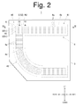
- Fig. 2 is a front view of a vehicle lighting unit 1 made in accordance with the principles of the present invention.
- Fig. 3 is a perspective view of essential parts of the vehicle lighting unit 1.
- Figs. 4 and 5 are cross-sectional views of the vehicle lighting unit taken along line III-III and line IV-IV of Fig. 2 , respectively.
- front means the respective directions when viewed from the vehicle lighting unit 1 mounted in place, unless otherwise specified.
- the vehicle lighting unit 1 can include a housing 2 opened forward and a plain outer lens 3 configured to cover the front opening of the housing 2.
- the housing 2 and the outer lens 3 can define a lighting chamber.
- an inner lens 4 and a plurality of (four in the present embodiment) light emitting diodes (LEDs) 5 can be accommodated.
- the inner lens 4 can be an elongated light guide bent in a letter U shape lying on its side to open leftward when viewed from the front side.
- the inner lens 4 being the elongated bent light guide can include a bending section 40 positioned at an upper right end of the inner lens 4, and also include a first light guiding section 41 configured to extend leftward along the left-to-right direction (horizontal direction) from the left end of the bending section 40, and a second light guiding section 41 configured to extend downward from the lower end of the bending section 40 and then be bent to extend leftward to be in a letter L shape.
- the inner lens 4 can be disposed at a certain position so that the respective left ends of the first and second light guiding sections are located to be aligned at the left end of the lighting chamber.
- a portion except for a rim portion with a predetermined width can be formed as a recessed section along the entire length of the inner lens 4, and a plurality of prism cuts 4a having a saw-tooth shaped cross section can be formed over the entire surface of the bottom face of the recessed section.
- the plurality of prism cuts 4a can be formed in parallel to each other and side by side along the extending direction of the first light guiding section 41 in the area corresponding to the first light guiding section 41 and the bending section 40 while the plurality of prism cuts 4a can be formed in parallel to each other and side by side along the extending direction of the second light guiding section 42 in the area corresponding to the second light guiding section 42.
- the plurality of prism cuts 4a can be configured to reflect light that has been emitted from the respective LEDs 5 and incident on the inner lens 4 to the front side while being guided along the respective extending directions within the areas of the first and second light guiding sections 41 and 42.
- the four incident sections 400 can be divided into two sets of two incident sections, one disposed at the right end portion and the other disposed on the upper end portion of the bending section 40.
- the two incident sections 400 provided at the right end portion of the bending section 40 can be arranged side by side in the vertical direction on the right side of the first light guiding section 41.
- the two incident sections 400 provided at the upper end portion of the bending section 40 can be arranged side by side in the left-to-right direction on the upper side of the first light guiding section 41. Further, the four incident sections 400 can be arranged to correspond to the four LEDs 5 described later so that the respective LEDs 5 are disposed in the rear of the corresponding incident sections 400 to face the corresponding incident sections 400.
- Each of the incident sections 400 can be formed to be a truncated conical shape projected rearward, and to have a concave portion 400a opened rearward at its rear end.
- each of the two incident sections 400 can be arranged side by side in the vertical direction at the right end portion of the bending section 40 to be elongated in the vertical direction while each of the two incident sections 400 can be arranged side by side in the left-to-right direction at the upper end portion of the bending section 40 to be elongated in the left-to-right direction.
- each of the concave portion 400a can be formed to be opened at both sides in the direction perpendicular to the lengthwise direction of the incident section 400.
- a first incident surface 401 of a convex surface (aspherical convex surface) bulged rearward can be formed.
- the first incident surface 401 can have a focus positioned at the position of the corresponding LED 5, so that the first incident surface 401 receives the light emitted from the LED 5 while collimates the same in the front-to-rear direction.
- a second incident surface 402 can be formed in the inner peripheral surface of the concave portion 400a.
- the second incident surface 402 can be formed to erect from the peripheral edge of the first incident surface 401 rearward and be a partial truncated conical shape, so that part of light emitted from the LED 5 directed sideward outside the first incident surface 401 can be allowed to enter the inner lens 4 (bending section 40).
- the outer peripheral surface of the incident section 400 can be formed to be an incident reflection surface 403.
- the incident reflection surface 403 can be shaped to be a partial truncated conical shape. The shape can be inclined to be spread outward and forward from the tip end (rear end) of the second incident surface 402 so that part of light emitted from the LED 5 incident on the second incident surface 402 and entering the inner lens 4 can be allowed to be internally reflected in the front-to-rear direction.
- a chamfered inclined surface 4b with an inclined angle of 45 degrees As shown in Figs. 1 to 3 , in the peripheral edge of the front surface and the peripheral surface of the inner lens 4 except for the inner side of the U-shape and the left end thereof, formed is a chamfered inclined surface 4b with an inclined angle of 45 degrees.
- a first reflection surface R1 can be formed in part of the inclined surface 4b at the right end portion of the bending section 40.
- the first reflection surface R1 can be positioned forward of the two incident sections 400 arranged at the right end portion of the rear portion of the bending section 40 and on the right side of the first light guiding section 41.
- the first reflection surface R1 can be inclined at 45 degrees both in the left-to-right and front-to-rear directions.
- the first reflection surface R1 can be configured to internally reflect the light from the two incident sections 400 to the first light guiding section 41 leftward in the left-to-right direction.
- a second reflection surface R2 can be formed in part of the inclined surface 4b at the upper end portion of the bending section 40.
- the second reflection surface R2 can be positioned forward of the two incident sections 400 arranged at the upper end portion of the rear portion of the bending section 40 and on the upper side of the right side portion (extending in the vertical direction) of the second light guiding section 42.
- the second reflection surface R2 can be inclined at 45 degrees both in the horizontal and vertical directions.
- the second reflection surface R2 can be configured to internally reflect the light from the two incident sections 400 downward toward the right side portion of the second light guiding section 42 in the vertical direction.
- the four LEDs 5 can be mounted on the front surface of the same substrate 6 extending in a direction perpendicular to the front-to-rear direction and located in the rear of the bending section 40 of the inner lens 4 so that their light emission surfaces are directed forward.
- the four LEDs 5 can include two first LEDs 51 and two second LEDs 52.
- the first LEDs 51 can be arranged side by side in the vertical direction in the rear of the right end portion of the bending section 40.
- the second LEDs 52 can be arranged side by side in the left-to-right direction in the rear of the upper end portion of the bending section 40.
- the first LEDs 51 can be configured to correspond to the two incident sections 400 disposed at the right end portion of the rear portion of the bending section 40 so as to face the two incident sections 400, i.e., in the rear of the first reflection surface R1.
- the second LEDs 52 can be configured to correspond to the two incident sections 400 disposed at the upper end portion of the rear portion of the bending section 40 so as to face the two incident sections 400, i.e., in the rear of the second reflection surface R2.
- the entire front surface of the inner lens 4 can become luminous uniformly.
- the two first LEDs 51 of the four LEDs 5 can emit light forward, and the two incident sections 400 arranged at the right end portion of the rear portion of the bending section 40 of the inner lens 4 can receive the light to collimate the same in the front-to-rear direction. Then, the light entering the inner lens 4 (bending section 40) can be reflected leftward by the first reflection surface R1. The reflected light can be guided within bending section 40 and the first light guiding section 41 leftward in the left-to-right direction so that the guided light can be reflected forward by the plurality of prism cuts 4a provided to the rear surface of the bending section 40 and the first light guiding section 41. Accordingly, the light can be projected through the front surface of the inner lens 4, whereby the surface of the bending section 40 and the first light guiding section 41 of the inner lens 4 can become luminance.
- the two second LEDs 52 of the four LEDs 5 can emit light forward, and the two incident sections 400 arranged at the upper end portion of the rear portion of the bending section 40 of the inner lens 4 can receive the light to collimate the same in the front-to-rear direction. Then, the light entering the inner lens 4 (bending section 40) can be reflected downward by the second reflection surface R2. The reflected light can be guided within the bending section 40 and the second light guiding section 42 downward as well as guided along the leftwardly bended second light guiding section 42 so that the guided light can be reflected forward by the plurality of prism cuts 4a provided to the rear surface of the second light guiding section 42. Accordingly, the light can be projected through the front surface of the inner lens 4, whereby the surface of the second light guiding section 42 of the inner lens 4 can become luminance.
- the light emitted forward from the first LEDs 51 can be incident on the inner lens 4 of the rear portion of the bending section 40 and then reflected by the first reflection surface R1 leftward in the left-to-right direction. Then the reflected light can be guided through the first light guiding section 41 and projected through the front surface of the first light guiding section 41. Further, the light emitted forward from the second LEDs 52 can be incident on the inner lens 4 of the rear portion of the bending section 40 and then reflected by the second reflection surface R2 downward in the vertical direction. Then the reflected light can be guided through the second light guiding section 42 and projected through the front surface of the second light guiding section 42.
- the inner lens 4 can become luminous more uniformly when compared with the case where a light source is arranged only at one end of a light guide in a conventional configuration.
- both the first and second LEDs 51 and 52 can be disposed in the rear of the bending section 40 of the inner lens 4.
- the first and second LEDs 51 and 52 can be collectively mounted on the single substrate 6.
- any concealing member for concealing a light source can be eliminated, and in turn, the parts number can be decreased.
- the above-mentioned vehicle lighting unit 1 can achieve the provision of the respective left ends of the first and second light guiding sections 41 and 42 opposite to the bending section 40 at the end portion of the lighting chamber.
- the LEDs 5 are described as light sources for the vehicle lighting unit 1 in the above-described embodiment, any light sources such as a laser diode (LD) or the like can be used as long as they can be mounted on a substrate.
- LD laser diode
- first and second light guiding sections 41 and 42 extend from the bending section 40 should not be limited to the left-to-right direction and vertical direction, but can be directions crossing each other when viewed from its front side (namely, in the illumination direction of the lighting unit).
Landscapes
- Engineering & Computer Science (AREA)
- General Engineering & Computer Science (AREA)
- Physics & Mathematics (AREA)
- Optics & Photonics (AREA)
- General Physics & Mathematics (AREA)
- Microelectronics & Electronic Packaging (AREA)
- Non-Portable Lighting Devices Or Systems Thereof (AREA)
- Planar Illumination Modules (AREA)
Abstract
Description
- The present invention relates to a vehicle lighting unit
- As one conventional example of various vehicle lighting units to be mounted in a vehicle body, those including an elongated light guide which is to be illuminated have been known. When a bent light guide such as those in the form of a letter U shape or the like is illuminated in this type of vehicle lighting unit, if a light source such as a light emitting diode (LED) is disposed only at one of ends of the elongated light guide, the light entering the light guide may be attenuated as it is guided therethrough. As a result, the uniformity of the light emission state in the lengthwise direction of the light guide may deteriorate. To cope with this problem, in general, both the ends of the light guide are configured to face respective light sources as shown in
Fig. 1 . (See, for example, Japanese Patent Application Laid-Open No.2012-243539 - However, this type of vehicle lighting unit should include light sources at two locations separated away from each other. This means two separate substrates for mounting the respective light sources are required, resulting in increasing parts number as compared with the case where only one light source is provided.
- In addition, since the light sources are disposed to face the respective ends of the elongated light guide, they must be concealed by some means (concealing members) such as extensions so that the light sources at two separate locations cannot be directly observed in front of them. This also causes the increased part number by the concealing members. This may also inhibit the provision of the vehicle lighting unit to a desired location in a vehicle body. Specifically, the end of the light guide cannot be located at the end of a lighting chamber due to the provision of the light source at the end of the light guide, meaning that the end of the lighting unit cannot be illuminated.
- The present invention was devised in view of these and other problems and features in association with the conventional art. According to an aspect of the present invention, a vehicle lighting unit can be configured to be capable of disposing a bent elongated light guide to be aligned to the end of a lighting chamber of the lighting unit while the uniformity of light emission state across the entire length of the bent elongated light guide can be ensured with less part number as compared with the conventional lighting unit.
- According to another aspect of the present invention, a vehicle lighting unit for emitting light in a front direction can include a light source mounted on a substrate, and an elongated light guide configured to receive light emitted from the light source and guide the light along its lengthwise direction so as to emit light from its front surface, the light guide having a first light guiding section and a second light guiding section, and a bending section between the first and second light guiding sections that extend in a first direction and a second direction, respectively, the first direction and the second direction crossing each other when viewed from its front side so that the light guide can bend at the bending section. In this configuration, the bending section can include a first reflection surface and a second reflection surface. The first reflection surface can internally reflect light from the rear side toward the first light guiding section substantially in the first direction. The second reflection surface can internally reflect the light from the rear side toward the second light guiding section substantially in the second direction. The light source can include a first light source and a second light source. The first light source can be disposed in the rear of the first reflection surface of the bending section while facing forward. The second light source can be disposed in the rear of the second reflection surface of the bending section while facing forward.
- In the above-described vehicle lighting unit, the substrate can extend to be orthogonal to the front-to-rear direction of the vehicle lighting unit and have a front surface, and the first and second light sources can be mounted on the front surface of the substrate.
- In the above-described vehicle lighting unit, the first reflection surface can be formed in the bending section at one of ends on a side opposite to the first light guiding section, and the second reflection surface can be formed in the bending section at one of ends on a side opposite to the second light guiding section.
- In the above-described vehicle lighting unit, the bending section can include a light incident section at its rear portion so that the light incident section faces the light source, the light incident section receiving light emitted from the light source so that the light can enter the bending section.
- In the above-described vehicle lighting unit, the light guide can have a rear surface including a plurality of prism cuts having a saw-tooth shaped cross section formed over substantially the entire rear surface so as to direct the guided light forward. Specifically, the rear surface can include a recessed section along the entire length of the light guide except for a rim portion with a predetermined width and the plurality of prism cuts can be formed in the bottom face of the recessed section. Furthermore, part the plurality of prism cuts can be formed in parallel to each other and side by side along the first direction in the area of the rear surface corresponding to the first light guiding section and the bending section while part of the plurality of prism cuts can be formed in parallel to each other and side by side along the extending direction of the second light guiding section in the area of the rear surface corresponding to the second light guiding section so that the plurality of prism cuts can reflect the light entering the light guide forward.
- In the vehicle lighting unit with the above-described configuration, the light emitted forward from the first light source can enter the light guide through the rear portion of the bending section and be reflected by the first reflection surface in the first direction, thereby being guided through the first guiding section to exit through the front surface of the first light guiding section. Further, the light emitted forward from the second light source can enter the light guide through the rear portion of the bending section and be reflected by the second reflection surface in the second direction, thereby being guided through the second guiding section to exit through the front surface of the second light guiding section.
- With this configuration, the first light guiding section and the second light guiding section of the light guide can independently become luminous by the respective first and second light sources. Accordingly, the resulting light guide can become luminous more uniformly when compared with the case where a light source is arranged only at one end of a light guide in a conventional configuration.
- In the vehicle lighting unit with the above-mentioned configuration, both the first and second light sources can be disposed in the rear of the bending section of the light guide. Thus, when compared with the conventional case where light sources are disposed to face respective ends of an elongated light guide, the first and second light sources can be collectively mounted on a single substrate. In addition to this, a concealing member for concealing a light source can be eliminated, and in turn, the parts number can be decreased. Even with this configuration, the above-mentioned vehicle lighting unit can achieve the provision of the respective ends of the first and second light guiding sections opposite to the bending section at the respective end portions of the lighting chamber.
- Therefore, with parts number less than the conventional lighting unit, it is possible to dispose an elongated bent light guide at respective end portions of the lighting chamber while the light guide can become luminous uniformly.
- These and other characteristics, features, and advantages of the present invention will become clear from the following description with reference to the accompanying drawings, wherein:
-
Fig. 1 is a front view of essential parts of a conventional vehicle lighting unit; -
Fig. 2 is a front view of a vehicle lighting unit made in accordance with principles of the present invention; -
Fig. 3 is a perspective view of essential parts of the vehicle lighting unit ofFig. 2 ; -
Fig. 4 is a cross-sectional view of the vehicle lighting unit taken along line III-III ofFig. 2 ; and -
Fig. 5 is a cross-sectional view of the vehicle lighting unit taken along line IV-IV ofFig. 2 . - A description will now be made below to vehicle lighting units of the present invention with reference to the accompanying drawings in accordance with exemplary embodiments.
-
Fig. 2 is a front view of avehicle lighting unit 1 made in accordance with the principles of the present invention.Fig. 3 is a perspective view of essential parts of thevehicle lighting unit 1.Figs. 4 and5 are cross-sectional views of the vehicle lighting unit taken along line III-III and line IV-IV ofFig. 2 , respectively. - In the present specification, the term "front," "rear (back)," "left," "right," "up (upper)," and "down (lower)" mean the respective directions when viewed from the
vehicle lighting unit 1 mounted in place, unless otherwise specified. - As shown in the drawings, the
vehicle lighting unit 1 can include ahousing 2 opened forward and a plainouter lens 3 configured to cover the front opening of thehousing 2. Thehousing 2 and theouter lens 3 can define a lighting chamber. Inside the lighting chamber, aninner lens 4 and a plurality of (four in the present embodiment) light emitting diodes (LEDs) 5 can be accommodated. - The
inner lens 4 can be an elongated light guide bent in a letter U shape lying on its side to open leftward when viewed from the front side. Specifically, theinner lens 4 being the elongated bent light guide can include abending section 40 positioned at an upper right end of theinner lens 4, and also include a firstlight guiding section 41 configured to extend leftward along the left-to-right direction (horizontal direction) from the left end of thebending section 40, and a secondlight guiding section 41 configured to extend downward from the lower end of thebending section 40 and then be bent to extend leftward to be in a letter L shape. Theinner lens 4 can be disposed at a certain position so that the respective left ends of the first and second light guiding sections are located to be aligned at the left end of the lighting chamber. - In the rear surface of the
inner lens 4, a portion except for a rim portion with a predetermined width can be formed as a recessed section along the entire length of theinner lens 4, and a plurality ofprism cuts 4a having a saw-tooth shaped cross section can be formed over the entire surface of the bottom face of the recessed section. Specifically, the plurality ofprism cuts 4a can be formed in parallel to each other and side by side along the extending direction of the firstlight guiding section 41 in the area corresponding to the firstlight guiding section 41 and thebending section 40 while the plurality ofprism cuts 4a can be formed in parallel to each other and side by side along the extending direction of the secondlight guiding section 42 in the area corresponding to the secondlight guiding section 42. The plurality ofprism cuts 4a can be configured to reflect light that has been emitted from therespective LEDs 5 and incident on theinner lens 4 to the front side while being guided along the respective extending directions within the areas of the first and secondlight guiding sections - At the rear portion of the
bending section 40 of theinner lens 4, there are formed a plurality of (four in the present embodiment)incident sections 400 on which light emitted from theLEDs 5 can be incident. - The four
incident sections 400 can be divided into two sets of two incident sections, one disposed at the right end portion and the other disposed on the upper end portion of thebending section 40. The twoincident sections 400 provided at the right end portion of thebending section 40 can be arranged side by side in the vertical direction on the right side of the firstlight guiding section 41. - The two
incident sections 400 provided at the upper end portion of thebending section 40 can be arranged side by side in the left-to-right direction on the upper side of the firstlight guiding section 41. Further, the fourincident sections 400 can be arranged to correspond to the fourLEDs 5 described later so that therespective LEDs 5 are disposed in the rear of thecorresponding incident sections 400 to face thecorresponding incident sections 400. - Each of the
incident sections 400 can be formed to be a truncated conical shape projected rearward, and to have aconcave portion 400a opened rearward at its rear end. Specifically, each of the twoincident sections 400 can be arranged side by side in the vertical direction at the right end portion of thebending section 40 to be elongated in the vertical direction while each of the twoincident sections 400 can be arranged side by side in the left-to-right direction at the upper end portion of thebending section 40 to be elongated in the left-to-right direction. Further, each of theconcave portion 400a can be formed to be opened at both sides in the direction perpendicular to the lengthwise direction of theincident section 400. - As shown in
Fig. 5 , in the bottom portion of the recessedsection 400a, afirst incident surface 401 of a convex surface (aspherical convex surface) bulged rearward can be formed. Thefirst incident surface 401 can have a focus positioned at the position of thecorresponding LED 5, so that thefirst incident surface 401 receives the light emitted from theLED 5 while collimates the same in the front-to-rear direction. - A
second incident surface 402 can be formed in the inner peripheral surface of theconcave portion 400a. Thesecond incident surface 402 can be formed to erect from the peripheral edge of thefirst incident surface 401 rearward and be a partial truncated conical shape, so that part of light emitted from theLED 5 directed sideward outside thefirst incident surface 401 can be allowed to enter the inner lens 4 (bending section 40). - The outer peripheral surface of the
incident section 400 can be formed to be anincident reflection surface 403. Theincident reflection surface 403 can be shaped to be a partial truncated conical shape. The shape can be inclined to be spread outward and forward from the tip end (rear end) of thesecond incident surface 402 so that part of light emitted from theLED 5 incident on thesecond incident surface 402 and entering theinner lens 4 can be allowed to be internally reflected in the front-to-rear direction. - As shown in
Figs. 1 to 3 , in the peripheral edge of the front surface and the peripheral surface of theinner lens 4 except for the inner side of the U-shape and the left end thereof, formed is a chamferedinclined surface 4b with an inclined angle of 45 degrees. - In this configuration, a first reflection surface R1 can be formed in part of the
inclined surface 4b at the right end portion of thebending section 40. The first reflection surface R1 can be positioned forward of the twoincident sections 400 arranged at the right end portion of the rear portion of thebending section 40 and on the right side of the firstlight guiding section 41. The first reflection surface R1 can be inclined at 45 degrees both in the left-to-right and front-to-rear directions. The first reflection surface R1 can be configured to internally reflect the light from the twoincident sections 400 to the firstlight guiding section 41 leftward in the left-to-right direction. - A second reflection surface R2 can be formed in part of the
inclined surface 4b at the upper end portion of thebending section 40. The second reflection surface R2 can be positioned forward of the twoincident sections 400 arranged at the upper end portion of the rear portion of thebending section 40 and on the upper side of the right side portion (extending in the vertical direction) of the secondlight guiding section 42. The second reflection surface R2 can be inclined at 45 degrees both in the horizontal and vertical directions. The second reflection surface R2 can be configured to internally reflect the light from the twoincident sections 400 downward toward the right side portion of the secondlight guiding section 42 in the vertical direction. - The four
LEDs 5 can be mounted on the front surface of thesame substrate 6 extending in a direction perpendicular to the front-to-rear direction and located in the rear of thebending section 40 of theinner lens 4 so that their light emission surfaces are directed forward. Specifically, the fourLEDs 5 can include twofirst LEDs 51 and twosecond LEDs 52. Thefirst LEDs 51 can be arranged side by side in the vertical direction in the rear of the right end portion of thebending section 40. Thesecond LEDs 52 can be arranged side by side in the left-to-right direction in the rear of the upper end portion of thebending section 40. - The
first LEDs 51 can be configured to correspond to the twoincident sections 400 disposed at the right end portion of the rear portion of thebending section 40 so as to face the twoincident sections 400, i.e., in the rear of the first reflection surface R1. - The
second LEDs 52 can be configured to correspond to the twoincident sections 400 disposed at the upper end portion of the rear portion of thebending section 40 so as to face the twoincident sections 400, i.e., in the rear of the second reflection surface R2. - In the
vehicle lighting unit 1 with the above-mentioned configuration, when the fourLEDs 5 are turned on, the entire front surface of theinner lens 4 can become luminous uniformly. - Specifically, the two
first LEDs 51 of the fourLEDs 5 can emit light forward, and the twoincident sections 400 arranged at the right end portion of the rear portion of thebending section 40 of theinner lens 4 can receive the light to collimate the same in the front-to-rear direction. Then, the light entering the inner lens 4 (bending section 40) can be reflected leftward by the first reflection surface R1. The reflected light can be guided within bendingsection 40 and the firstlight guiding section 41 leftward in the left-to-right direction so that the guided light can be reflected forward by the plurality ofprism cuts 4a provided to the rear surface of thebending section 40 and the firstlight guiding section 41. Accordingly, the light can be projected through the front surface of theinner lens 4, whereby the surface of thebending section 40 and the firstlight guiding section 41 of theinner lens 4 can become luminance. - The two
second LEDs 52 of the fourLEDs 5 can emit light forward, and the twoincident sections 400 arranged at the upper end portion of the rear portion of thebending section 40 of theinner lens 4 can receive the light to collimate the same in the front-to-rear direction. Then, the light entering the inner lens 4 (bending section 40) can be reflected downward by the second reflection surface R2. The reflected light can be guided within thebending section 40 and the secondlight guiding section 42 downward as well as guided along the leftwardly bended secondlight guiding section 42 so that the guided light can be reflected forward by the plurality ofprism cuts 4a provided to the rear surface of the secondlight guiding section 42. Accordingly, the light can be projected through the front surface of theinner lens 4, whereby the surface of the secondlight guiding section 42 of theinner lens 4 can become luminance. - As described, according to the
vehicle lighting unit 1 of the present embodiment, the light emitted forward from thefirst LEDs 51 can be incident on theinner lens 4 of the rear portion of thebending section 40 and then reflected by the first reflection surface R1 leftward in the left-to-right direction. Then the reflected light can be guided through the firstlight guiding section 41 and projected through the front surface of the firstlight guiding section 41. Further, the light emitted forward from thesecond LEDs 52 can be incident on theinner lens 4 of the rear portion of thebending section 40 and then reflected by the second reflection surface R2 downward in the vertical direction. Then the reflected light can be guided through the secondlight guiding section 42 and projected through the front surface of the secondlight guiding section 42. - Since the first and second
light guiding sections inner lens 4 can independently become luminous by the first andsecond LEDs inner lens 4 can become luminous more uniformly when compared with the case where a light source is arranged only at one end of a light guide in a conventional configuration. - In the
vehicle lighting unit 1 with the above-mentioned configuration, both the first andsecond LEDs bending section 40 of theinner lens 4. Thus, when compared with the conventional case where light sources are disposed to face respective ends of an elongated light guide, the first andsecond LEDs single substrate 6. In addition to this, any concealing member for concealing a light source can be eliminated, and in turn, the parts number can be decreased. Even with this configuration, the above-mentionedvehicle lighting unit 1 can achieve the provision of the respective left ends of the first and secondlight guiding sections bending section 40 at the end portion of the lighting chamber. - Therefore, with parts number less than the conventional lighting unit, it is possible to dispose the elongated bent
inner lens 4 at the end portion of the lighting chamber while theinner lens 4 can become luminous uniformly. - Note that the embodiments to which the present invention can be applied should not be limited to the described embodiments, but may be appropriately modified within the scope departing from the sprit or scope of the present invention.
- For example, although the
LEDs 5 are described as light sources for thevehicle lighting unit 1 in the above-described embodiment, any light sources such as a laser diode (LD) or the like can be used as long as they can be mounted on a substrate. - Further, the respective directions in which the first and second
light guiding sections section 40 should not be limited to the left-to-right direction and vertical direction, but can be directions crossing each other when viewed from its front side (namely, in the illumination direction of the lighting unit).
Claims (7)
- A vehicle lighting unit (1) for emitting light in a front direction, the vehicle lighting unit (1) comprising:a light source (5) mounted on a substrate (6); andan elongated light guide (4) configured to receive light emitted from the light source (5) and guide the light along its lengthwise direction so as to emit light from its front surface,the light guide (4) having a first light guiding section (41) and a second light guiding section (42), and a bending section (40) between the first and second light guiding sections (41, 42) that extend in a first direction and a second direction, respectively, the first direction and the second direction crossing each other when viewed from a front side of the vehicle lighting unit (1) so that the light guide (4) bends at the bending section (40), whereinthe bending section (40) includes a first reflection surface (R1) and a second reflection surface (R2), the first reflection surface (R1) internally reflecting light from the rear side toward the first light guiding section (41) substantially in the first direction, the second reflection surface (R2) internally reflecting the light from the rear side toward the second light guiding section (42) substantially in the second direction,the light source (5) includes a first light source (51) and a second light source (52), the first light source (51) being disposed in the rear of the first reflection surface (R1) of the bending section (40) while facing forward, and the second light source (52) being disposed in the rear of the second reflection surface (R2) of the bending section (40) while facing forward.
- The vehicle lighting unit (1) according to claim 1,
wherein the substrate (6) extends to be orthogonal to a front-to-rear direction of the vehicle lighting unit (1) and have a front surface, and the first and second light sources (51, 52) are mounted on the front surface of the substrate (6). - The vehicle lighting unit (1) according to claim 1 or 2, wherein the first reflection surface (R1) is formed in the bending section (40) at one of ends on a side opposite to the first light guiding section (41), and
the second reflection surface (R2) is formed in the bending section (40) at one of ends on a side opposite to the second light guiding section (42). - The vehicle lighting unit (1) according to any one of claims 1 to 3, wherein the bending section (40) includes a light incident section (400) at a rear portion of the bending section (40) so that the light incident section (400) faces the light source (5), the light incident section (400) receiving light emitted from the light source (5) so that the light can enter the bending section (40).
- The vehicle lighting unit (1) according to any one of claims 1 to 4, wherein the light guide (4) has a rear surface including a plurality of prism cuts (4a) having a saw-tooth shaped cross section formed over substantially the entire rear surface so as to direct the guided light forward.
- The vehicle lighting unit (1) according to claim 5,
wherein the rear surface includes a recessed section along the entire length of the light guide (4) except for a rim portion with a predetermined width and the plurality of prism cuts (4a) are formed in a bottom face of the recessed section. - The vehicle lighting unit (1) according to claim 5 or 6, wherein part of the plurality of prism cuts (4a) are formed in parallel to each other and side by side along the first direction in an area of the rear surface corresponding to the first light guiding section (41) and the bending section (40), and part of the plurality of prism cuts (4a) are formed in parallel to each other and side by side along an extending direction of the second light guiding section (42) in an area of the rear surface corresponding to the second light guiding section (42) so that the plurality of prism cuts (4a) can reflect the light entering the light guide (4) forward.
Applications Claiming Priority (1)
| Application Number | Priority Date | Filing Date | Title |
|---|---|---|---|
| JP2013014908A JP6166541B2 (en) | 2013-01-30 | 2013-01-30 | Vehicle lighting |
Publications (2)
| Publication Number | Publication Date |
|---|---|
| EP2762770A1 true EP2762770A1 (en) | 2014-08-06 |
| EP2762770B1 EP2762770B1 (en) | 2021-08-25 |
Family
ID=50033328
Family Applications (1)
| Application Number | Title | Priority Date | Filing Date |
|---|---|---|---|
| EP14020011.4A Active EP2762770B1 (en) | 2013-01-30 | 2014-01-30 | Vehicle lighting unit |
Country Status (3)
| Country | Link |
|---|---|
| US (1) | US9328885B2 (en) |
| EP (1) | EP2762770B1 (en) |
| JP (1) | JP6166541B2 (en) |
Cited By (2)
| Publication number | Priority date | Publication date | Assignee | Title |
|---|---|---|---|---|
| EP3599418A1 (en) * | 2018-07-23 | 2020-01-29 | Stanley Electric Co., Ltd. | Vehicular lamp comprising a light guide |
| EP3657069A1 (en) * | 2018-11-22 | 2020-05-27 | Mazda Motor Corporation | Vehicle light |
Families Citing this family (19)
| Publication number | Priority date | Publication date | Assignee | Title |
|---|---|---|---|---|
| ITTV20110098A1 (en) * | 2011-07-11 | 2013-01-12 | Automotive Lighting Italia Spa | AUTOMOTIVE HEADLIGHT |
| JP6235948B2 (en) * | 2014-03-27 | 2017-11-22 | 株式会社小糸製作所 | Vehicle lighting |
| JP6530928B2 (en) * | 2015-02-24 | 2019-06-12 | スタンレー電気株式会社 | Lighting device |
| KR102288453B1 (en) * | 2015-02-25 | 2021-08-10 | 현대모비스 주식회사 | Lamp apparatus for an automobile |
| FR3036774B1 (en) * | 2015-05-27 | 2019-04-05 | Valeo Vision Belgique | LUMINOUS DEVICE, IN PARTICULAR FOR A MOTOR VEHICLE, AND LIGHTING BOX COMPRISING SUCH A DEVICE |
| KR101755866B1 (en) | 2015-10-23 | 2017-07-10 | 현대자동차주식회사 | Light source module of lamp for vehicle |
| US10088118B2 (en) * | 2016-08-30 | 2018-10-02 | HELLA GmbH & Co. KGaA | Light emitting area extender |
| CN207262329U (en) * | 2017-04-27 | 2018-04-20 | 法雷奥照明湖北技术中心有限公司 | Beam steering devices and vehicle lamp assembly |
| JP6967460B2 (en) * | 2018-01-09 | 2021-11-17 | サカエ理研工業株式会社 | Vehicle lighting |
| JP6970627B2 (en) * | 2018-02-23 | 2021-11-24 | サカエ理研工業株式会社 | Vehicle lighting |
| CN115264452B (en) * | 2018-03-14 | 2025-05-30 | 株式会社小糸制作所 | Vehicle lighting |
| JP7020259B2 (en) * | 2018-04-09 | 2022-02-16 | トヨタ自動車株式会社 | Vehicle lighting |
| JP7309341B2 (en) * | 2018-10-24 | 2023-07-18 | スタンレー電気株式会社 | vehicle lamp |
| JP7292074B2 (en) * | 2019-03-22 | 2023-06-16 | スタンレー電気株式会社 | vehicle lamp |
| TWI745984B (en) | 2020-05-27 | 2021-11-11 | 敏翔股份有限公司 | Car lights |
| US11512828B2 (en) * | 2020-12-01 | 2022-11-29 | Valeo Vision | Automotive lamp optical system with light diffusive projection lens |
| US11220210B1 (en) * | 2021-07-13 | 2022-01-11 | Ford Global Technologies, Llc | Light pipe |
| CN117693711A (en) * | 2022-06-29 | 2024-03-12 | 京东方科技集团股份有限公司 | Curved optical plate and manufacturing method thereof, backlight module and display device |
| DE102023208414A1 (en) * | 2022-09-08 | 2024-03-14 | Hyundai Mobis Co., Ltd. | LIGHTING DEVICE |
Citations (7)
| Publication number | Priority date | Publication date | Assignee | Title |
|---|---|---|---|---|
| WO2001028815A2 (en) * | 1999-10-21 | 2001-04-26 | Federal-Mogul Corporation | Vehicle side mirror assembly with integral illumination and signal lighting |
| EP2048430A2 (en) * | 2007-10-10 | 2009-04-15 | Hella KGaA Hueck & Co. | Illumination device for vehicles |
| JP2012004004A (en) * | 2010-06-18 | 2012-01-05 | Koito Mfg Co Ltd | Lighting fixture for vehicle |
| US20120069592A1 (en) * | 2010-09-17 | 2012-03-22 | Koito Manufacturing Co., Ltd. | Vehicular lamp |
| US20120099310A1 (en) * | 2010-01-11 | 2012-04-26 | Visteon Global Technologies, Inc. | Light guide module with adjustable contour surface illumination |
| DE102010027648A1 (en) * | 2009-07-20 | 2012-05-10 | Magna Mirrors Holding Gmbh | Signal light unit for vehicle exterior mirror, has multiple longitudinal optical fiber bodies and multiple light units for illuminating coupling section of assigned optical-fiber body |
| JP2012243539A (en) | 2011-05-19 | 2012-12-10 | Stanley Electric Co Ltd | Light guide lens and vehicular lamp |
Family Cites Families (6)
| Publication number | Priority date | Publication date | Assignee | Title |
|---|---|---|---|---|
| BR9811170A (en) * | 1997-08-12 | 2000-07-25 | Decoma Int Inc | Bi-reflective lens kit and light emitting kit for use in a vehicle |
| ES2168071B1 (en) * | 2000-07-12 | 2003-07-16 | Barros Alejandro Rodriguez | MODULAR REAR VIEW MIRROR WITH INTERCHANGEABLE MULTIPLE SIGNALS FOR VEHICLES OF 2, 3, 4 OR MORE WHEELS. |
| FR2853392B1 (en) * | 2003-04-04 | 2006-06-16 | Sli Miniature Lighting Sa | REAR LIGHT, ESPECIALLY STOP LIGHT FOR MOTOR VEHICLE |
| JP2005158362A (en) * | 2003-11-21 | 2005-06-16 | Stanley Electric Co Ltd | Vehicle lighting |
| US20100246200A1 (en) * | 2009-03-30 | 2010-09-30 | Osram Sylvania Inc. | Automotive taillight light guide |
| JP2012169116A (en) * | 2011-02-14 | 2012-09-06 | Stanley Electric Co Ltd | Lamp for vehicle |
-
2013
- 2013-01-30 JP JP2013014908A patent/JP6166541B2/en not_active Expired - Fee Related
-
2014
- 2014-01-30 EP EP14020011.4A patent/EP2762770B1/en active Active
- 2014-01-30 US US14/168,942 patent/US9328885B2/en active Active
Patent Citations (7)
| Publication number | Priority date | Publication date | Assignee | Title |
|---|---|---|---|---|
| WO2001028815A2 (en) * | 1999-10-21 | 2001-04-26 | Federal-Mogul Corporation | Vehicle side mirror assembly with integral illumination and signal lighting |
| EP2048430A2 (en) * | 2007-10-10 | 2009-04-15 | Hella KGaA Hueck & Co. | Illumination device for vehicles |
| DE102010027648A1 (en) * | 2009-07-20 | 2012-05-10 | Magna Mirrors Holding Gmbh | Signal light unit for vehicle exterior mirror, has multiple longitudinal optical fiber bodies and multiple light units for illuminating coupling section of assigned optical-fiber body |
| US20120099310A1 (en) * | 2010-01-11 | 2012-04-26 | Visteon Global Technologies, Inc. | Light guide module with adjustable contour surface illumination |
| JP2012004004A (en) * | 2010-06-18 | 2012-01-05 | Koito Mfg Co Ltd | Lighting fixture for vehicle |
| US20120069592A1 (en) * | 2010-09-17 | 2012-03-22 | Koito Manufacturing Co., Ltd. | Vehicular lamp |
| JP2012243539A (en) | 2011-05-19 | 2012-12-10 | Stanley Electric Co Ltd | Light guide lens and vehicular lamp |
Cited By (4)
| Publication number | Priority date | Publication date | Assignee | Title |
|---|---|---|---|---|
| EP3599418A1 (en) * | 2018-07-23 | 2020-01-29 | Stanley Electric Co., Ltd. | Vehicular lamp comprising a light guide |
| US10823900B2 (en) | 2018-07-23 | 2020-11-03 | Stanley Electric Co., Ltd. | Vehicular lamp with elongated light guide portions |
| EP3657069A1 (en) * | 2018-11-22 | 2020-05-27 | Mazda Motor Corporation | Vehicle light |
| US10995930B2 (en) | 2018-11-22 | 2021-05-04 | Mazda Motor Corporation | Vehicle light |
Also Published As
| Publication number | Publication date |
|---|---|
| US9328885B2 (en) | 2016-05-03 |
| JP6166541B2 (en) | 2017-07-19 |
| US20140211493A1 (en) | 2014-07-31 |
| JP2014146521A (en) | 2014-08-14 |
| EP2762770B1 (en) | 2021-08-25 |
Similar Documents
| Publication | Publication Date | Title |
|---|---|---|
| US9328885B2 (en) | Vehicle lighting unit | |
| US10036526B2 (en) | Light guiding lens and vehicle lighting unit | |
| US10036522B2 (en) | Vehicular lamp | |
| US10371341B2 (en) | Vehicle lamp | |
| US9701240B2 (en) | Vehicle lighting unit having light guiding lens | |
| JP7278920B2 (en) | Light guide lens, lens assembly and vehicle lamp | |
| JP6560514B2 (en) | Vehicle lighting | |
| CN106338032B (en) | Light guide lens and lamp | |
| US10436406B2 (en) | Vehicle lamp fitting | |
| US10816159B2 (en) | Vehicle lamp | |
| EP2489550A2 (en) | Vehicle lamp | |
| US10823900B2 (en) | Vehicular lamp with elongated light guide portions | |
| JP2017062963A (en) | Vehicle lighting | |
| US9797568B2 (en) | Vehicle lighting unit | |
| CN111473296B (en) | Lamp unit for vehicle | |
| JP6438686B2 (en) | Vehicle lamp | |
| US10234615B2 (en) | Illumination device | |
| JP2016212988A (en) | Vehicular lamp | |
| JP2016212949A (en) | Vehicular lamp | |
| US10837618B2 (en) | Vehicular lamp | |
| JP6476048B2 (en) | Vehicle lighting | |
| JP6619584B2 (en) | Light guide | |
| CN113002417B (en) | Vehicle lighting | |
| JP2024089797A (en) | Vehicle Lighting | |
| JP2016100230A (en) | Vehicle lighting |
Legal Events
| Date | Code | Title | Description |
|---|---|---|---|
| PUAI | Public reference made under article 153(3) epc to a published international application that has entered the european phase |
Free format text: ORIGINAL CODE: 0009012 |
|
| 17P | Request for examination filed |
Effective date: 20140130 |
|
| AK | Designated contracting states |
Kind code of ref document: A1 Designated state(s): AL AT BE BG CH CY CZ DE DK EE ES FI FR GB GR HR HU IE IS IT LI LT LU LV MC MK MT NL NO PL PT RO RS SE SI SK SM TR |
|
| AX | Request for extension of the european patent |
Extension state: BA ME |
|
| R17P | Request for examination filed (corrected) |
Effective date: 20150206 |
|
| RBV | Designated contracting states (corrected) |
Designated state(s): AL AT BE BG CH CY CZ DE DK EE ES FI FR GB GR HR HU IE IS IT LI LT LU LV MC MK MT NL NO PL PT RO RS SE SI SK SM TR |
|
| STAA | Information on the status of an ep patent application or granted ep patent |
Free format text: STATUS: EXAMINATION IS IN PROGRESS |
|
| 17Q | First examination report despatched |
Effective date: 20191024 |
|
| REG | Reference to a national code |
Ref country code: DE Ref legal event code: R079 Ref document number: 602014079624 Country of ref document: DE Free format text: PREVIOUS MAIN CLASS: F21S0008100000 Ipc: F21S0043140000 |
|
| GRAP | Despatch of communication of intention to grant a patent |
Free format text: ORIGINAL CODE: EPIDOSNIGR1 |
|
| STAA | Information on the status of an ep patent application or granted ep patent |
Free format text: STATUS: GRANT OF PATENT IS INTENDED |
|
| RIC1 | Information provided on ipc code assigned before grant |
Ipc: F21S 43/241 20180101ALI20210225BHEP Ipc: F21S 43/14 20180101AFI20210225BHEP Ipc: F21S 43/245 20180101ALI20210225BHEP Ipc: F21S 43/237 20180101ALI20210225BHEP Ipc: F21S 43/249 20180101ALI20210225BHEP |
|
| INTG | Intention to grant announced |
Effective date: 20210324 |
|
| RAP3 | Party data changed (applicant data changed or rights of an application transferred) |
Owner name: STANLEY ELECTRIC CO., LTD. |
|
| GRAS | Grant fee paid |
Free format text: ORIGINAL CODE: EPIDOSNIGR3 |
|
| GRAA | (expected) grant |
Free format text: ORIGINAL CODE: 0009210 |
|
| STAA | Information on the status of an ep patent application or granted ep patent |
Free format text: STATUS: THE PATENT HAS BEEN GRANTED |
|
| AK | Designated contracting states |
Kind code of ref document: B1 Designated state(s): AL AT BE BG CH CY CZ DE DK EE ES FI FR GB GR HR HU IE IS IT LI LT LU LV MC MK MT NL NO PL PT RO RS SE SI SK SM TR |
|
| REG | Reference to a national code |
Ref country code: GB Ref legal event code: FG4D |
|
| REG | Reference to a national code |
Ref country code: CH Ref legal event code: EP |
|
| REG | Reference to a national code |
Ref country code: IE Ref legal event code: FG4D Ref country code: AT Ref legal event code: REF Ref document number: 1424158 Country of ref document: AT Kind code of ref document: T Effective date: 20210915 |
|
| REG | Reference to a national code |
Ref country code: DE Ref legal event code: R096 Ref document number: 602014079624 Country of ref document: DE |
|
| REG | Reference to a national code |
Ref country code: LT Ref legal event code: MG9D |
|
| REG | Reference to a national code |
Ref country code: NL Ref legal event code: MP Effective date: 20210825 |
|
| REG | Reference to a national code |
Ref country code: AT Ref legal event code: MK05 Ref document number: 1424158 Country of ref document: AT Kind code of ref document: T Effective date: 20210825 |
|
| PG25 | Lapsed in a contracting state [announced via postgrant information from national office to epo] |
Ref country code: HR Free format text: LAPSE BECAUSE OF FAILURE TO SUBMIT A TRANSLATION OF THE DESCRIPTION OR TO PAY THE FEE WITHIN THE PRESCRIBED TIME-LIMIT Effective date: 20210825 Ref country code: SE Free format text: LAPSE BECAUSE OF FAILURE TO SUBMIT A TRANSLATION OF THE DESCRIPTION OR TO PAY THE FEE WITHIN THE PRESCRIBED TIME-LIMIT Effective date: 20210825 Ref country code: RS Free format text: LAPSE BECAUSE OF FAILURE TO SUBMIT A TRANSLATION OF THE DESCRIPTION OR TO PAY THE FEE WITHIN THE PRESCRIBED TIME-LIMIT Effective date: 20210825 Ref country code: PT Free format text: LAPSE BECAUSE OF FAILURE TO SUBMIT A TRANSLATION OF THE DESCRIPTION OR TO PAY THE FEE WITHIN THE PRESCRIBED TIME-LIMIT Effective date: 20211227 Ref country code: NO Free format text: LAPSE BECAUSE OF FAILURE TO SUBMIT A TRANSLATION OF THE DESCRIPTION OR TO PAY THE FEE WITHIN THE PRESCRIBED TIME-LIMIT Effective date: 20211125 Ref country code: FI Free format text: LAPSE BECAUSE OF FAILURE TO SUBMIT A TRANSLATION OF THE DESCRIPTION OR TO PAY THE FEE WITHIN THE PRESCRIBED TIME-LIMIT Effective date: 20210825 Ref country code: ES Free format text: LAPSE BECAUSE OF FAILURE TO SUBMIT A TRANSLATION OF THE DESCRIPTION OR TO PAY THE FEE WITHIN THE PRESCRIBED TIME-LIMIT Effective date: 20210825 Ref country code: AT Free format text: LAPSE BECAUSE OF FAILURE TO SUBMIT A TRANSLATION OF THE DESCRIPTION OR TO PAY THE FEE WITHIN THE PRESCRIBED TIME-LIMIT Effective date: 20210825 Ref country code: BG Free format text: LAPSE BECAUSE OF FAILURE TO SUBMIT A TRANSLATION OF THE DESCRIPTION OR TO PAY THE FEE WITHIN THE PRESCRIBED TIME-LIMIT Effective date: 20211125 Ref country code: LT Free format text: LAPSE BECAUSE OF FAILURE TO SUBMIT A TRANSLATION OF THE DESCRIPTION OR TO PAY THE FEE WITHIN THE PRESCRIBED TIME-LIMIT Effective date: 20210825 |
|
| PG25 | Lapsed in a contracting state [announced via postgrant information from national office to epo] |
Ref country code: PL Free format text: LAPSE BECAUSE OF FAILURE TO SUBMIT A TRANSLATION OF THE DESCRIPTION OR TO PAY THE FEE WITHIN THE PRESCRIBED TIME-LIMIT Effective date: 20210825 Ref country code: LV Free format text: LAPSE BECAUSE OF FAILURE TO SUBMIT A TRANSLATION OF THE DESCRIPTION OR TO PAY THE FEE WITHIN THE PRESCRIBED TIME-LIMIT Effective date: 20210825 Ref country code: GR Free format text: LAPSE BECAUSE OF FAILURE TO SUBMIT A TRANSLATION OF THE DESCRIPTION OR TO PAY THE FEE WITHIN THE PRESCRIBED TIME-LIMIT Effective date: 20211126 |
|
| PG25 | Lapsed in a contracting state [announced via postgrant information from national office to epo] |
Ref country code: NL Free format text: LAPSE BECAUSE OF FAILURE TO SUBMIT A TRANSLATION OF THE DESCRIPTION OR TO PAY THE FEE WITHIN THE PRESCRIBED TIME-LIMIT Effective date: 20210825 |
|
| PG25 | Lapsed in a contracting state [announced via postgrant information from national office to epo] |
Ref country code: DK Free format text: LAPSE BECAUSE OF FAILURE TO SUBMIT A TRANSLATION OF THE DESCRIPTION OR TO PAY THE FEE WITHIN THE PRESCRIBED TIME-LIMIT Effective date: 20210825 |
|
| REG | Reference to a national code |
Ref country code: DE Ref legal event code: R097 Ref document number: 602014079624 Country of ref document: DE |
|
| PG25 | Lapsed in a contracting state [announced via postgrant information from national office to epo] |
Ref country code: SM Free format text: LAPSE BECAUSE OF FAILURE TO SUBMIT A TRANSLATION OF THE DESCRIPTION OR TO PAY THE FEE WITHIN THE PRESCRIBED TIME-LIMIT Effective date: 20210825 Ref country code: SK Free format text: LAPSE BECAUSE OF FAILURE TO SUBMIT A TRANSLATION OF THE DESCRIPTION OR TO PAY THE FEE WITHIN THE PRESCRIBED TIME-LIMIT Effective date: 20210825 Ref country code: RO Free format text: LAPSE BECAUSE OF FAILURE TO SUBMIT A TRANSLATION OF THE DESCRIPTION OR TO PAY THE FEE WITHIN THE PRESCRIBED TIME-LIMIT Effective date: 20210825 Ref country code: EE Free format text: LAPSE BECAUSE OF FAILURE TO SUBMIT A TRANSLATION OF THE DESCRIPTION OR TO PAY THE FEE WITHIN THE PRESCRIBED TIME-LIMIT Effective date: 20210825 Ref country code: CZ Free format text: LAPSE BECAUSE OF FAILURE TO SUBMIT A TRANSLATION OF THE DESCRIPTION OR TO PAY THE FEE WITHIN THE PRESCRIBED TIME-LIMIT Effective date: 20210825 Ref country code: AL Free format text: LAPSE BECAUSE OF FAILURE TO SUBMIT A TRANSLATION OF THE DESCRIPTION OR TO PAY THE FEE WITHIN THE PRESCRIBED TIME-LIMIT Effective date: 20210825 |
|
| PLBE | No opposition filed within time limit |
Free format text: ORIGINAL CODE: 0009261 |
|
| STAA | Information on the status of an ep patent application or granted ep patent |
Free format text: STATUS: NO OPPOSITION FILED WITHIN TIME LIMIT |
|
| PG25 | Lapsed in a contracting state [announced via postgrant information from national office to epo] |
Ref country code: IT Free format text: LAPSE BECAUSE OF FAILURE TO SUBMIT A TRANSLATION OF THE DESCRIPTION OR TO PAY THE FEE WITHIN THE PRESCRIBED TIME-LIMIT Effective date: 20210825 |
|
| 26N | No opposition filed |
Effective date: 20220527 |
|
| PG25 | Lapsed in a contracting state [announced via postgrant information from national office to epo] |
Ref country code: SI Free format text: LAPSE BECAUSE OF FAILURE TO SUBMIT A TRANSLATION OF THE DESCRIPTION OR TO PAY THE FEE WITHIN THE PRESCRIBED TIME-LIMIT Effective date: 20210825 Ref country code: MC Free format text: LAPSE BECAUSE OF FAILURE TO SUBMIT A TRANSLATION OF THE DESCRIPTION OR TO PAY THE FEE WITHIN THE PRESCRIBED TIME-LIMIT Effective date: 20210825 |
|
| REG | Reference to a national code |
Ref country code: CH Ref legal event code: PL |
|
| REG | Reference to a national code |
Ref country code: BE Ref legal event code: MM Effective date: 20220131 |
|
| PG25 | Lapsed in a contracting state [announced via postgrant information from national office to epo] |
Ref country code: LU Free format text: LAPSE BECAUSE OF NON-PAYMENT OF DUE FEES Effective date: 20220130 |
|
| PG25 | Lapsed in a contracting state [announced via postgrant information from national office to epo] |
Ref country code: BE Free format text: LAPSE BECAUSE OF NON-PAYMENT OF DUE FEES Effective date: 20220131 |
|
| PG25 | Lapsed in a contracting state [announced via postgrant information from national office to epo] |
Ref country code: LI Free format text: LAPSE BECAUSE OF NON-PAYMENT OF DUE FEES Effective date: 20220131 Ref country code: CH Free format text: LAPSE BECAUSE OF NON-PAYMENT OF DUE FEES Effective date: 20220131 |
|
| PG25 | Lapsed in a contracting state [announced via postgrant information from national office to epo] |
Ref country code: IE Free format text: LAPSE BECAUSE OF NON-PAYMENT OF DUE FEES Effective date: 20220130 |
|
| PGFP | Annual fee paid to national office [announced via postgrant information from national office to epo] |
Ref country code: GB Payment date: 20231207 Year of fee payment: 11 |
|
| PGFP | Annual fee paid to national office [announced via postgrant information from national office to epo] |
Ref country code: FR Payment date: 20231212 Year of fee payment: 11 |
|
| PG25 | Lapsed in a contracting state [announced via postgrant information from national office to epo] |
Ref country code: HU Free format text: LAPSE BECAUSE OF FAILURE TO SUBMIT A TRANSLATION OF THE DESCRIPTION OR TO PAY THE FEE WITHIN THE PRESCRIBED TIME-LIMIT; INVALID AB INITIO Effective date: 20140130 |
|
| PG25 | Lapsed in a contracting state [announced via postgrant information from national office to epo] |
Ref country code: MK Free format text: LAPSE BECAUSE OF FAILURE TO SUBMIT A TRANSLATION OF THE DESCRIPTION OR TO PAY THE FEE WITHIN THE PRESCRIBED TIME-LIMIT Effective date: 20210825 Ref country code: CY Free format text: LAPSE BECAUSE OF FAILURE TO SUBMIT A TRANSLATION OF THE DESCRIPTION OR TO PAY THE FEE WITHIN THE PRESCRIBED TIME-LIMIT Effective date: 20210825 |
|
| PGFP | Annual fee paid to national office [announced via postgrant information from national office to epo] |
Ref country code: DE Payment date: 20231205 Year of fee payment: 11 |
|
| PG25 | Lapsed in a contracting state [announced via postgrant information from national office to epo] |
Ref country code: TR Free format text: LAPSE BECAUSE OF FAILURE TO SUBMIT A TRANSLATION OF THE DESCRIPTION OR TO PAY THE FEE WITHIN THE PRESCRIBED TIME-LIMIT Effective date: 20210825 |
|
| PG25 | Lapsed in a contracting state [announced via postgrant information from national office to epo] |
Ref country code: MT Free format text: LAPSE BECAUSE OF FAILURE TO SUBMIT A TRANSLATION OF THE DESCRIPTION OR TO PAY THE FEE WITHIN THE PRESCRIBED TIME-LIMIT Effective date: 20210825 |
|
| REG | Reference to a national code |
Ref country code: DE Ref legal event code: R119 Ref document number: 602014079624 Country of ref document: DE |
|
| GBPC | Gb: european patent ceased through non-payment of renewal fee |
Effective date: 20250130 |
|
| PG25 | Lapsed in a contracting state [announced via postgrant information from national office to epo] |
Ref country code: DE Free format text: LAPSE BECAUSE OF NON-PAYMENT OF DUE FEES Effective date: 20250801 |
|
| PG25 | Lapsed in a contracting state [announced via postgrant information from national office to epo] |
Ref country code: GB Free format text: LAPSE BECAUSE OF NON-PAYMENT OF DUE FEES Effective date: 20250130 |
|
| PG25 | Lapsed in a contracting state [announced via postgrant information from national office to epo] |
Ref country code: FR Free format text: LAPSE BECAUSE OF NON-PAYMENT OF DUE FEES Effective date: 20250131 |