EP2762735A1 - Direct lubrication-type tilting pad journal bearing - Google Patents
Direct lubrication-type tilting pad journal bearing Download PDFInfo
- Publication number
- EP2762735A1 EP2762735A1 EP11873327.8A EP11873327A EP2762735A1 EP 2762735 A1 EP2762735 A1 EP 2762735A1 EP 11873327 A EP11873327 A EP 11873327A EP 2762735 A1 EP2762735 A1 EP 2762735A1
- Authority
- EP
- European Patent Office
- Prior art keywords
- rotation shaft
- oil
- pad
- circumferential surface
- collection path
- Prior art date
- Legal status (The legal status is an assumption and is not a legal conclusion. Google has not performed a legal analysis and makes no representation as to the accuracy of the status listed.)
- Withdrawn
Links
Images




Classifications
-
- F—MECHANICAL ENGINEERING; LIGHTING; HEATING; WEAPONS; BLASTING
- F16—ENGINEERING ELEMENTS AND UNITS; GENERAL MEASURES FOR PRODUCING AND MAINTAINING EFFECTIVE FUNCTIONING OF MACHINES OR INSTALLATIONS; THERMAL INSULATION IN GENERAL
- F16C—SHAFTS; FLEXIBLE SHAFTS; ELEMENTS OR CRANKSHAFT MECHANISMS; ROTARY BODIES OTHER THAN GEARING ELEMENTS; BEARINGS
- F16C17/00—Sliding-contact bearings for exclusively rotary movement
- F16C17/02—Sliding-contact bearings for exclusively rotary movement for radial load only
- F16C17/03—Sliding-contact bearings for exclusively rotary movement for radial load only with tiltably-supported segments, e.g. Michell bearings
-
- F—MECHANICAL ENGINEERING; LIGHTING; HEATING; WEAPONS; BLASTING
- F16—ENGINEERING ELEMENTS AND UNITS; GENERAL MEASURES FOR PRODUCING AND MAINTAINING EFFECTIVE FUNCTIONING OF MACHINES OR INSTALLATIONS; THERMAL INSULATION IN GENERAL
- F16C—SHAFTS; FLEXIBLE SHAFTS; ELEMENTS OR CRANKSHAFT MECHANISMS; ROTARY BODIES OTHER THAN GEARING ELEMENTS; BEARINGS
- F16C33/00—Parts of bearings; Special methods for making bearings or parts thereof
- F16C33/02—Parts of sliding-contact bearings
- F16C33/04—Brasses; Bushes; Linings
- F16C33/06—Sliding surface mainly made of metal
- F16C33/10—Construction relative to lubrication
- F16C33/1025—Construction relative to lubrication with liquid, e.g. oil, as lubricant
- F16C33/1045—Details of supply of the liquid to the bearing
-
- F—MECHANICAL ENGINEERING; LIGHTING; HEATING; WEAPONS; BLASTING
- F16—ENGINEERING ELEMENTS AND UNITS; GENERAL MEASURES FOR PRODUCING AND MAINTAINING EFFECTIVE FUNCTIONING OF MACHINES OR INSTALLATIONS; THERMAL INSULATION IN GENERAL
- F16C—SHAFTS; FLEXIBLE SHAFTS; ELEMENTS OR CRANKSHAFT MECHANISMS; ROTARY BODIES OTHER THAN GEARING ELEMENTS; BEARINGS
- F16C33/00—Parts of bearings; Special methods for making bearings or parts thereof
- F16C33/02—Parts of sliding-contact bearings
- F16C33/04—Brasses; Bushes; Linings
- F16C33/06—Sliding surface mainly made of metal
- F16C33/10—Construction relative to lubrication
- F16C33/1025—Construction relative to lubrication with liquid, e.g. oil, as lubricant
- F16C33/106—Details of distribution or circulation inside the bearings, e.g. details of the bearing surfaces to affect flow or pressure of the liquid
- F16C33/1065—Grooves on a bearing surface for distributing or collecting the liquid
Definitions
- This invention relates to a tilting pad journal bearing used for high-speed rotating machines such as turbines, and specifically to a direct lubrication tilting pad journal bearing.
- a tilting pad journal bearing as shown in NPL 1 is used.
- the tilting pad journal bearing has a plurality of pads placed at the outer circumferential side of a rotation shaft and swingably provided. Further, oil films are formed between the outer circumferential surface of the rotation shaft and the inner circumferential surfaces of the pads (hereinafter, referred to as "sliding parts"), and thereby, bear the radial load of the rotation shaft while preventing contact between the rotation shaft and the pads.
- the tilting pad journal bearing is roughly divided into two depending on oil feeding systems.
- One system is called an oil bath system of filling pad holding spaces of a housing with lubricating oil to immersing the sliding parts.
- the other system is called a direct lubrication system of directly feeding lubricating oil to the sliding parts with a plurality of nozzles placed between the plurality of pads, not filling the pad holding spaces of the housing with lubricating oil (for example, see PTL 1).
- the direct lubrication system has advantages, compared to the oil bath system, that oil at a relatively low temperature may be fed to the sliding parts, the temperature of the sliding parts is easily reduced, and the quantity of oil feed may be made relatively small.
- NPL 1 Edited by Japanese Society of Tribologists, Tribology Handbook, Yokendo (2001), pp. 53-57
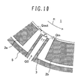
- Fig. 10 is a partially enlarged sectional view of a bearing for explanation of oil flow in a structure of related art
- Fig. 10 is a partially enlarged sectional view of a bearing for explanation of oil flow in a structure of related art
- a rotation shaft 1 is rotating in the rotation direction shown by an arrow R in the drawing.
- the oil flowing out from the upstream sliding part joins oil fed from a nozzle 3, and is fed to the downstream sliding part (in detail, between the outer circumferential surface of the rotation shaft 1 and the inner circumferential surface of a downstream pad 2b).
- the upstream pad 2a does not vibrate, the quantity Q out of oil outflow from the upstream sliding part is constant and the quantity (Q out + Q0) of oil feed to the downstream sliding part is also constant.
- the necessary oil inflow quantity Q in ' may not be secured (i.e., the actual oil inflow quantity Q in ⁇ Q in '), and the oil film is insufficient in the downstream sliding part. Accordingly, the oil film in the downstream sliding part unstably changes and vibration is generated in the pad 2b, and then, vibration of the rotation shaft 1 is caused.
- An object of the invention is to provide a direct lubrication tilting pad journal bearing that can suppress vibration without increase in a quantity of oil feed from nozzles.
- vibration may be suppressed without increase in the quantity of oil feed from the nozzle.
- Fig. 1 is a sectional view showing a structure of a direct lubrication tilting pad journal bearing in the embodiment.
- Fig. 2 is a perspective view showing a structure of a pad in the embodiment with a nozzle.
- the direct lubrication tilting pad journal bearing includes, for example, five pads 2a to 2e (hereinafter, appropriately and representatively referred to as "pad 2”) placed at the outer circumferential side of a rotation shaft and swingably supported via pivots 4, five nozzle 3a to 3e provided between the pads 2a to 2e (hereinafter, appropriately and representatively referred to as "nozzle 3"), and a casing 5 housing the pads 2a to 2e and the nozzles 3a to 3e etc.
- the rotation shaft 1 extends in the horizontal direction and the pads 2a, 2e are located upside of the rotation shaft 1. Further, the rotation shaft 1 is rotating in the rotation direction shown by an arrow R in Fig. 1 .
- Pad holding spaces of the housing 5 are not filled with lubricating oil and the lubricating oil is fed to the nozzles 3a to 3e via an annular oil feed path (not shown) formed at the outer circumferential side of the housing 5.
- the oil from an oil feed port at the end of the nozzle 3a is directly fed between the outer circumferential surface of the rotation shaft 1 and the inner circumferential surface of the pad 2a
- the oil from an oil feed port at the end of the nozzle 3b is directly fed between the outer circumferential surface of the rotation shaft 1 and the inner circumferential surface of the pad 2b
- the oil from an oil feed port at the end of the nozzle 3c is directly fed between the outer circumferential surface of the rotation shaft 1 and the inner circumferential surface of the pad 2c
- the oil from an oil feed port at the end of the nozzle 3d is directly fed between the outer circumferential surface of the rotation shaft 1 and the inner circumferential surface of the pad 2d
- a groove-shaped oil collection path (in other words, oil feed groove) 6 is formed by cutting work or molding.
- the oil collection path 6 is formed by cutting out one side of the pad 2 so that an inlet 7 may open in the opposite end surface (the left surface in Fig. 2 ) to the rotation direction of the rotation shaft 1 in the pad 2, an outlet 8 may open in the inner circumferential surface of the pad 2 (the upper surface in Fig. 2 ), and the inlet 7 and the outlet 8 may continuously open.
- a width dimension w2 of the oil collection path 6 in the axial direction of the rotation shaft 1 is smaller than a width dimension w1 of the pad.
- the width dimension w2 of the oil collection path 6 is constant toward the rotation direction of the rotation shaft 1.
- a depth dimension h from the outer circumferential surface of the rotation shaft 1 to the bottom surface of the oil collection path 6 of the pad 2 in the radial direction of the rotation shaft 1 is larger than a distance d1 from the outer circumferential surface of the rotation shaft 1 to the end of the nozzle 3 in the radial direction of the rotation shaft 1, for example, about twice.
- the distance d1 from the outer circumferential surface of the rotation shaft 1 to the end of the nozzle 3 is about five times to ten times a gap dimension d0 between the outer circumferential surface of the rotation shaft 1 and the inner circumferential surface of the pad 2, and thus, the depth dimension h from the outer circumferential surface of the rotation shaft 1 to the bottom surface of the oil collection path 6 of the pad 2 is larger than five times the above described gap dimension d0, for example, about ten times to twenty times. Further, in the embodiment, the depth dimension h from the outer circumferential surface of the rotation shaft 1 to the bottom surface of the oil collection path 6 of the pad 2 is constant toward the rotation direction of the rotation shaft 1.
- Fig. 3 is a partially enlarged sectional view of the bearing for explanation of oil flow in the embodiment.
- Fig. 4 shows temporal change of quantity Q out of oil outflow from an upstream sliding part, quantity Q0 of oil feed from the nozzle 3, temporal change of quantity (Q out + Q0) of oil feed to a downstream sliding part, quantity Q in ' of oil inflow necessary for the downstream sliding part, and temporal change of quantity Q in of actual oil inflow in the downstream sliding part in the embodiment.
- the oil flowing out from the upstream sliding part joins the oil fed from the nozzle 3b and fed to the downstream sliding part (in detail, between the outer circumferential surface of the rotation shaft 1 and the inner circumferential surface of the downstream pad 2b).
- the upstream pad 2a does not vibrate, the quantity Q out of oil outflow from the upstream sliding part is constant and the quantity (Q out + Q0) of oil feed to the downstream sliding part is also constant.
- the oil from the upstream sliding part and the nozzle 3b may be temporarily accumulated in the oil collection path 6 of the downstream pad 2b.
- the depth dimension h from the outer circumferential surface of the rotation shaft 1 to the bottom surface of the oil collection path 6 of the pad 2 is larger than the distance d from the outer circumferential surface of the rotation shaft 1 to the end of the nozzle 3, and thus, the oil from the upper sliding part and the nozzle 3 easily flows into the oil collection path 6 of the downstream pad 2b, and the quantity of oil temporarily accumulated in the oil collection path 6 may be secured.
- the quantity Q in of oil inflow in the downstream sliding part may be stabilized, and the oil film in the downstream sliding part may be stabilized. Therefore, vibration may be suppressed without increase in the quantity Q0 of oil feed from the nozzle 3.
- the configuration including the five pads 2a to 2e and the five nozzles 3a to 3e has been explained as an example, but not limited to that. Obviously, it is only necessary that a plurality of pads 2 and a plurality of nozzles 3 are provided.
- Fig. 5 is a perspective view showing a structure of a pad 2 in the embodiment with a nozzle 3.
- the oil collection path 6 of the pad 2 has bottom surfaces 9a, 9b. Further, the depth dimension h from the outer circumferential surface of the rotation shaft 1 to the bottom surface 9a of the oil collection path 6 of the pad 2 is larger than the distance d from the outer circumferential surface of the rotation shaft 1 to the end of the nozzle 3 and constant toward the rotation direction of the rotation shaft 1. On the other hand, a depth dimension from the outer circumferential surface of the rotation shaft 1 to the bottom surface 9b of the oil collection path 6 of the pad 2 is gradually smaller toward the rotation direction of the rotation shaft 1. That is, the bottom surface 9b of the oil collection path 6 of the pad 2 is formed to incline in the rotation direction of the rotation shaft 1.
- vibration may be suppressed without increase in the quantity Q0 of oil feed from the nozzle 3.
- the depth dimension from the outer circumferential surface of the rotation shaft 1 to the bottom surface of the oil collection path 6 of the pad 2 is gradually smaller toward the rotation direction of the rotation shaft 1, and thus, the oil easily flows from the oil collection path 6 of the pad 2 into the inner circumferential surface of the pad 2, and the oil film may be stabilized. Thereby, the vibration may be further suppressed.
- the bottom surface of the oil collection path 6 of the pad 2 is formed to partially incline has been explained as an example, but not limited to that.
- a whole bottom surface 9 of the oil collection path 6 of the pad 2 may be formed to incline.
- the depth dimension h in the inlet of the oil collection path 6 of the pad 2 is larger than the distance d from the outer circumferential surface of the rotation shaft 1 to the end of the nozzle 3.
- the same advantages as those of the second embodiment may be obtained.
- a third embodiment of the invention will be explained with reference to Fig. 7 . Note that, in the embodiment, the equal parts to those of the second embodiment have the same signs and their explanation will be appropriately omitted.
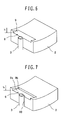
- Fig. 7 is a perspective view showing a structure of a pad 2 in the embodiment with a nozzle 3.
- the nozzle 3 is provided so that at least part of the end (a half of the section in the embodiment) may be located nearer the rotation direction side of the rotation shaft 1 than the inlet 7 of the oil collection path 6 of the pad 2. That is, a cutout 10 for placement of the nozzle 3 is formed on the opposite end surface to the rotation direction of the rotation shaft 1 in the pad 2, and the nozzle 3 is placed not to interfere with the pad 2.
- vibration may be suppressed without increase in the quantity of oil feed from the nozzle 3.
- at least part of the end of the nozzle 3 is located nearer the rotation direction side of the rotation shaft 1 than an inlet 6a of the oil collection path 6 of the pad 2, and thus, the oil from the nozzle 3 flows into the oil collection path 6 of the pad 2 without spattering in the axial direction of the rotation shaft 1. Thereby, the quantity of oil feed from the nozzle 3 may be suppressed.
- Fig. 8 is a perspective view showing a structure of a pad 2 in the embodiment with a nozzle 3.
- the oil collection path 6 of the pad 2 has bottom surfaces 9c, 9d, 9e, 9f. Further, the bottom surfaces 9d, 9e, 9f of the oil collection path 6 of the pad 2 are formed to incline in the rotation direction of the rotation shaft 1. Thereby, the depth dimension from the outer circumferential surface of the rotation shaft 1 to the bottom surface of the oil collection path 6 of the pad 2 is gradually smaller toward the rotation direction of the rotation shaft 1. Further, the bottom surfaces 9d, 9f of the oil collection path 6 of the pad 2 are formed to incline in the width direction of the pad 2. Thereby, the width dimension of the oil collection path 6 is gradually smaller toward the rotation direction of the rotation shaft.
- vibration may be suppressed without increase in the quantity of oil feed from the nozzle 3.
- the depth dimension from the outer circumferential surface of the rotation shaft 1 to the bottom surface of the oil collection path 6 of the pad 2 is gradually smaller toward the rotation direction of the rotation shaft 1 and the width dimension of the oil collection path 6 is gradually smaller toward the rotation direction of the rotation shaft 1, and thus, the oil easily flows from the oil collection path 6 of the pad 2 into the inner circumferential surface of the pad 2, and the oil film may be stabilized. Thereby, the vibration may be further suppressed.
Landscapes
- Engineering & Computer Science (AREA)
- General Engineering & Computer Science (AREA)
- Mechanical Engineering (AREA)
- Chemical & Material Sciences (AREA)
- Oil, Petroleum & Natural Gas (AREA)
- Physics & Mathematics (AREA)
- Fluid Mechanics (AREA)
- Sliding-Contact Bearings (AREA)
Abstract
A direct lubrication tilting pad journal bearing that may suppress vibration without increasing a quantity of oil feed from nozzles is provided.
In the direct lubrication tilting pad journal bearing, a pad 2 has an oil collection path 6 in a groove shape. The oil collection path 6 is formed so that an inlet 7 may open in an opposite end surface to a rotation direction of a rotation shaft 1 in the pad 2, an outlet 8 may open in an inner circumferential surface of the pad 2, and the inlet 7 and the outlet 8 may continuously open. Further, a width dimension w2 of the oil collection path 6 is smaller than a width dimension w1 of the pad 2. Furthermore, a depth dimension h from an outer circumferential surface of the rotation shaft 1 to a bottom surface of the oil collection path 6 is larger than a distance d from the outer circumferential surface of the rotation shaft 1 to an end of a nozzle 3.
Description
- This invention relates to a tilting pad journal bearing used for high-speed rotating machines such as turbines, and specifically to a direct lubrication tilting pad journal bearing.
- In high-speed rotating machines such as turbines, for example, a tilting pad journal bearing as shown in
NPL 1 is used. The tilting pad journal bearing has a plurality of pads placed at the outer circumferential side of a rotation shaft and swingably provided. Further, oil films are formed between the outer circumferential surface of the rotation shaft and the inner circumferential surfaces of the pads (hereinafter, referred to as "sliding parts"), and thereby, bear the radial load of the rotation shaft while preventing contact between the rotation shaft and the pads. - The tilting pad journal bearing is roughly divided into two depending on oil feeding systems. One system is called an oil bath system of filling pad holding spaces of a housing with lubricating oil to immersing the sliding parts. The other system is called a direct lubrication system of directly feeding lubricating oil to the sliding parts with a plurality of nozzles placed between the plurality of pads, not filling the pad holding spaces of the housing with lubricating oil (for example, see PTL 1). The direct lubrication system has advantages, compared to the oil bath system, that oil at a relatively low temperature may be fed to the sliding parts, the temperature of the sliding parts is easily reduced, and the quantity of oil feed may be made relatively small.
- PTL 1:
JP-A-11-182535 - NPL 1: Edited by Japanese Society of Tribologists, Tribology Handbook, Yokendo (2001), pp. 53-57
- The tilting pad journal bearing is regarded as being unlikely to produce vibration such as oil whip and oil whirl generated at high-speed rotation exceeding the critical speed. However, in the direct lubrication tilting pad journal bearing, the quantity of oil feed may be insufficient and vibration may occur depending on the operation condition. The vibration phenomenon will be explained using
Figs. 10 and11 .Fig. 10 is a partially enlarged sectional view of a bearing for explanation of oil flow in a structure of related art, andFig. 11 shows temporal change of quantity Qout of oil outflow from the upstream sliding part, quantity Q0 of oil feed from a nozzle, temporal change of quantity (Qout + Q0) of oil feed to the downstream sliding part, quantity Qin' of oil inflow necessary for the downstream sliding part, and temporal change of quantity Qin of actual oil inflow in the downstream sliding part in the structure of related art. - In
Fig. 10 , arotation shaft 1 is rotating in the rotation direction shown by an arrow R in the drawing. Further, the oil flowing out from the upstream sliding part (in detail, between the outer circumferential surface of therotation shaft 1 and the inner circumferential surface of anupstream pad 2a) joins oil fed from anozzle 3, and is fed to the downstream sliding part (in detail, between the outer circumferential surface of therotation shaft 1 and the inner circumferential surface of adownstream pad 2b). In this regard, if theupstream pad 2a does not vibrate, the quantity Qout of oil outflow from the upstream sliding part is constant and the quantity (Qout + Q0) of oil feed to the downstream sliding part is also constant. Accordingly, for example, the oil feed quantity Q0 is determined so that the relationship of (Qout + Q0) = Qin' may be satisfied (or the quantity (Qout + Q0) of oil feed to the downstream sliding part may be slightly larger than the necessary oil inflow quantity Qin'). - However, depending on the operation condition, load may become smaller in the
pad 2a (in detail, for example, the pad located upside of the rotation shaft extending in the horizontal direction or the like), pressure generated on the oil film may become lower, and vibration may be generated in thepad 2a as an initial phenomenon of the shaft vibration. In this case, as shown inFig. 11 , the quantity Qout of oil outflow from the upstream sliding part varies. Accordingly, the quantity (Qout + Q0) of oil feed to the downstream sliding part also varies above and below the necessary oil inflow quantity Qin'. Further, when the quantity (Qout + Q0) of oil feed to the downstream sliding part is larger than the necessary oil inflow quantity Qin' (see time A inFig. 11 ), the excess (shaded parts in the drawing) flows down between thepad 2a and thepad 2b, but the necessary oil inflow quantity Qin' is secured (i.e., the actual oil inflow quantity Qin = Qin'), and thus, the oil film is sufficiently formed in the downstream sliding part. On the other hand, when the quantity (Qout + Q0) of oil feed to the downstream sliding part is smaller than the necessary oil inflow quantity Qin' (see time B inFig. 11 ), the necessary oil inflow quantity Qin' may not be secured (i.e., the actual oil inflow quantity Qin < Qin'), and the oil film is insufficient in the downstream sliding part. Accordingly, the oil film in the downstream sliding part unstably changes and vibration is generated in thepad 2b, and then, vibration of therotation shaft 1 is caused. - As one of methods for suppressing the vibration, there is a conceivable method of increasing the quantity Q0 of oil feed from the
nozzle 3 to maintain the relationship of (Qout + Q0) ≥ Qin' even when the quantity Qout of oil outflow from the upstream sliding part varies. However, in this case, the advantages of employment of the direct lubrication system are lost. - An object of the invention is to provide a direct lubrication tilting pad journal bearing that can suppress vibration without increase in a quantity of oil feed from nozzles.
-
- (1) To achieve the object, the invention is that, in a direct lubrication tilting pad journal bearing including a plurality of pads placed at an outer circumferential side of a rotation shaft and swingably provided, and a plurality of nozzles that are provided between the plurality of pads and directly feed oil between an outer circumferential surface of the rotation shaft and inner circumferential surfaces of the pads, the pad has an oil collection path in a groove shape formed so that an inlet may open to an opposite lateral side to a rotation direction of the rotation shaft in the pad, an outlet may open to an inner circumferential side of the pad, and the inlet and the outlet may continuously open, a width dimension of the oil collection path in an axial direction of the rotation shaft is smaller than a width dimension of the pad, and a depth dimension from the outer circumferential surface of the rotation shaft to a bottom surface of the oil collection path in a radial direction of the rotation shaft is larger than a distance from the outer circumferential surface of the rotation shaft to an end of the nozzle in the radial direction of the rotation shaft.
In the invention, the oil flowing out from between the outer circumferential surface of the rotation shaft and the inner circumferential surface of the upstream pad (in other words, the upper sliding part) and the oil fed from the nozzle may be temporarily accumulated in the oil collection path of the downstream pad. Particularly, the depth dimension from the outer circumferential surface of the rotation shaft to the bottom surface of the oil collection path of the pad is larger than the distance from the outer circumferential surface of the rotation shaft to the end of the nozzle, and the oil from the upstream sliding part and the nozzle easily flows into the oil collection path of the downstream pad and the quantity of oil temporarily accumulated in the oil collection path may be secured. Thereby, if the upstream pad vibrates and the quantity of oil outflow from the upstream sliding part varies as the initial phenomenon of shaft vibration, the excess is accumulated in the oil collection path when the quantity of oil outflow from the upstream sliding part is larger and then the oil is supplied from the oil accumulated in the oil collection path when the quantity of oil outflow from the upstream sliding part is smaller, and thus, the quantity of oil inflow in the downstream sliding part may be stabilized. Therefore, the oil film in the downstream sliding part may be stabilized and vibration may be suppressed.
As described above, in the invention, vibration may be suppressed without increase in the quantity of oil feed from the nozzle. - (2) In the (1), preferably, the depth dimension from the outer circumferential surface of the rotation shaft to the bottom surface of the oil collection path in the radial direction of the rotation shaft is larger than five times a gap dimension between the outer circumferential surface of the rotation shaft and the inner circumferential surface of the pad.
- (3) In the (1) or (2), preferably, the depth dimension from the outer circumferential surface of the rotation shaft to the bottom surface of the oil collection path in the radial direction of the rotation shaft is gradually smaller toward the rotation direction of the rotation shaft.
- (4) In any one of the (1) to (3), preferably, the nozzle is provided so that at least part of the end may be located nearer the rotation direction side of the rotation shaft than the inlet of the oil collection path.
- (5) In any one of the (1) to (4), preferably, the width dimension of the oil collection path in the axial direction of the rotation shaft is gradually smaller toward the rotation direction of the rotation shaft.
- According to the invention, vibration may be suppressed without increase in the quantity of oil feed from the nozzle.
-
- [
Fig. 1] Fig. 1 is a sectional view showing a structure of a direct lubrication tilting pad journal bearing in a first embodiment of the invention. - [
Fig. 2] Fig. 2 is a perspective view showing a structure of a pad in the first embodiment of the invention with a nozzle. - [
Fig. 3] Fig. 3 is a partially enlarged sectional view of the bearing for explanation of oil flow in the first embodiment of the invention. - [
Fig. 4] Fig. 4 shows temporal change of quantity Qout of oil outflow from an upstream sliding part, quantity Q0 of oil feed from anozzle 3, temporal change of quantity (Qout + Q0) of oil feed to a downstream sliding part, quantity Qin' of oil inflow necessary for the downstream sliding part, and temporal change of quantity Qin of actual oil inflow in the downstream sliding part in the first embodiment of the invention. - [
Fig. 5] Fig. 5 is a perspective view showing a structure of a pad in a second embodiment of the invention with a nozzle. - [
Fig. 6] Fig. 6 is a perspective view showing a structure of a pad in one modified example of the invention with a nozzle. - [
Fig. 7] Fig. 7 is a perspective view showing a structure of a pad in a third embodiment of the invention with a nozzle. - [
Fig. 8] Fig. 8 is a perspective view showing a structure of a pad in a fourth embodiment of the invention with a nozzle. - [
Fig. 9] Fig. 9 is a perspective view showing a structure of a pad in another modified example of the invention with a nozzle. - [
Fig. 10] Fig. 10 is a partially enlarged sectional view of a bearing for explanation of oil flow in a structure of related art. - [
Fig. 11] Fig. 11 shows temporal change of quantity Qout of oil outflow from an upstream sliding part, quantity Q0 of oil feed from anozzle 3, temporal change of quantity (Qout + Q0) of oil feed to a downstream sliding part, quantity Qin' of oil inflow necessary for the downstream sliding part, and temporal change of quantity Qin of actual oil inflow in the downstream sliding part in the structure of related art. - A first embodiment of the invention will be explained with reference to
Figs. 1 to 4 . -
Fig. 1 is a sectional view showing a structure of a direct lubrication tilting pad journal bearing in the embodiment.Fig. 2 is a perspective view showing a structure of a pad in the embodiment with a nozzle. - In
Figs. 1 and 2 , the direct lubrication tilting pad journal bearing includes, for example, fivepads 2a to 2e (hereinafter, appropriately and representatively referred to as "pad 2") placed at the outer circumferential side of a rotation shaft and swingably supported viapivots 4, fivenozzle 3a to 3e provided between thepads 2a to 2e (hereinafter, appropriately and representatively referred to as "nozzle 3"), and acasing 5 housing thepads 2a to 2e and thenozzles 3a to 3e etc. Note that, in the embodiment, therotation shaft 1 extends in the horizontal direction and thepads rotation shaft 1. Further, therotation shaft 1 is rotating in the rotation direction shown by an arrow R inFig. 1 . - Pad holding spaces of the
housing 5 are not filled with lubricating oil and the lubricating oil is fed to thenozzles 3a to 3e via an annular oil feed path (not shown) formed at the outer circumferential side of thehousing 5. Further, the oil from an oil feed port at the end of thenozzle 3a is directly fed between the outer circumferential surface of therotation shaft 1 and the inner circumferential surface of thepad 2a, the oil from an oil feed port at the end of thenozzle 3b is directly fed between the outer circumferential surface of therotation shaft 1 and the inner circumferential surface of thepad 2b, the oil from an oil feed port at the end of thenozzle 3c is directly fed between the outer circumferential surface of therotation shaft 1 and the inner circumferential surface of thepad 2c, the oil from an oil feed port at the end of thenozzle 3d is directly fed between the outer circumferential surface of therotation shaft 1 and the inner circumferential surface of thepad 2d, and the oil from an oil feed port at the end of thenozzle 3e is directly fed between the outer circumferential surface of therotation shaft 1 and the inner circumferential surface of thepad 2e. Thereby, the oil at a relatively low temperature may be fed between the outer circumferential surface of therotation shaft 1 and the inner circumferential surface of thepad 2, and the quantity of oil feed may be made smaller. - Further, when the
rotation shaft 1 rotates, the oil is caught between the outer circumferential surface of therotation shaft 1 and the inner circumferential surface of thepad 2, and an oil film is formed. Therotation shaft 1 is lifted by the pressure generated in the oil films and supported without direct contact with thepads 2a to 2e. - Here, as a great feature of the embodiment, in each
pad 2, for example, a groove-shaped oil collection path (in other words, oil feed groove) 6 is formed by cutting work or molding. Theoil collection path 6 is formed by cutting out one side of thepad 2 so that aninlet 7 may open in the opposite end surface (the left surface inFig. 2 ) to the rotation direction of therotation shaft 1 in thepad 2, anoutlet 8 may open in the inner circumferential surface of the pad 2 (the upper surface inFig. 2 ), and theinlet 7 and theoutlet 8 may continuously open. Further, a width dimension w2 of theoil collection path 6 in the axial direction of therotation shaft 1 is smaller than a width dimension w1 of the pad. Furthermore, in the embodiment, the width dimension w2 of theoil collection path 6 is constant toward the rotation direction of therotation shaft 1. - In addition, as will be shown in
Fig. 3 later, a depth dimension h from the outer circumferential surface of therotation shaft 1 to the bottom surface of theoil collection path 6 of thepad 2 in the radial direction of therotation shaft 1 is larger than a distance d1 from the outer circumferential surface of therotation shaft 1 to the end of thenozzle 3 in the radial direction of therotation shaft 1, for example, about twice. Note that the distance d1 from the outer circumferential surface of therotation shaft 1 to the end of thenozzle 3 is about five times to ten times a gap dimension d0 between the outer circumferential surface of therotation shaft 1 and the inner circumferential surface of thepad 2, and thus, the depth dimension h from the outer circumferential surface of therotation shaft 1 to the bottom surface of theoil collection path 6 of thepad 2 is larger than five times the above described gap dimension d0, for example, about ten times to twenty times. Further, in the embodiment, the depth dimension h from the outer circumferential surface of therotation shaft 1 to the bottom surface of theoil collection path 6 of thepad 2 is constant toward the rotation direction of therotation shaft 1. - Next, the advantageous effects of the invention will be explained using
Figs. 3 and4 .Fig. 3 is a partially enlarged sectional view of the bearing for explanation of oil flow in the embodiment.Fig. 4 shows temporal change of quantity Qout of oil outflow from an upstream sliding part, quantity Q0 of oil feed from thenozzle 3, temporal change of quantity (Qout + Q0) of oil feed to a downstream sliding part, quantity Qin' of oil inflow necessary for the downstream sliding part, and temporal change of quantity Qin of actual oil inflow in the downstream sliding part in the embodiment. - As shown in
Fig. 3 , the oil flowing out from the upstream sliding part (in detail, between the outer circumferential surface of therotation shaft 1 and the inner circumferential surface of theupstream pad 2a) joins the oil fed from thenozzle 3b and fed to the downstream sliding part (in detail, between the outer circumferential surface of therotation shaft 1 and the inner circumferential surface of thedownstream pad 2b). In this regard, if theupstream pad 2a does not vibrate, the quantity Qout of oil outflow from the upstream sliding part is constant and the quantity (Qout + Q0) of oil feed to the downstream sliding part is also constant. Accordingly, the quantity Q0 of oil feed is determined so that the relationship of (Qout + Q0) = Qin' may be satisfied (or the quantity (Qout + Q) of oil feed to the downstream sliding part may be slightly larger than the necessary oil inflow quantity Qin'). - However, depending on the operation condition, load may become smaller in the
pad 2a, pressure generated on the oil film may become lower, and vibration may be generated in thepad 2a as an initial phenomenon of shaft vibration. In this case, as shown inFig. 4 , the quantity Qout of oil outflow from the upstream sliding part varies. Accordingly, the quantity (Qout + Q0) of oil feed to the downstream sliding part also varies above and below the necessary oil inflow quantity Qin'. - Here, in the embodiment, the oil from the upstream sliding part and the
nozzle 3b may be temporarily accumulated in theoil collection path 6 of thedownstream pad 2b. Particularly, the depth dimension h from the outer circumferential surface of therotation shaft 1 to the bottom surface of theoil collection path 6 of thepad 2 is larger than the distance d from the outer circumferential surface of therotation shaft 1 to the end of thenozzle 3, and thus, the oil from the upper sliding part and thenozzle 3 easily flows into theoil collection path 6 of thedownstream pad 2b, and the quantity of oil temporarily accumulated in theoil collection path 6 may be secured. - Further, if the quantity (Qout + Q0) of oil feed to the downstream sliding part is larger than the necessary oil inflow quantity Qin' (see time domain A in
Fig. 4 ), the necessary oil inflow quantity Qin' may be secured (i.e., the actual oil inflow quantity Qin = Qin') and the excess (shaded parts in the drawing) flows into theoil collection path 6 of thedownstream pad 2b and may be temporarily accumulated. Then, if the quantity (Qout + Q0) of oil feed to the downstream sliding part is smaller than the necessary oil inflow quantity Qin' (see time domain B inFig. 11 ), the oil is supplied from the oil accumulated in theoil collection path 6 of thedownstream pad 2b, and thus, the necessary oil inflow quantity Qin' may be secured (i.e., the actual oil inflow quantity Qin = Qin'). Thereby, the quantity Qin of oil inflow in the downstream sliding part may be stabilized, and the oil film in the downstream sliding part may be stabilized. Therefore, vibration may be suppressed without increase in the quantity Q0 of oil feed from thenozzle 3. - Note that, in the first embodiment, the configuration including the five
pads 2a to 2e and the fivenozzles 3a to 3e has been explained as an example, but not limited to that. Obviously, it is only necessary that a plurality ofpads 2 and a plurality ofnozzles 3 are provided. - A second embodiment of the invention will be explained with reference to
Fig. 5 . Note that, in the embodiment, the equal parts to those of the first embodiment have the same signs and their explanation will be appropriately omitted. -
Fig. 5 is a perspective view showing a structure of apad 2 in the embodiment with anozzle 3. - In the embodiment, the
oil collection path 6 of thepad 2 hasbottom surfaces rotation shaft 1 to thebottom surface 9a of theoil collection path 6 of thepad 2 is larger than the distance d from the outer circumferential surface of therotation shaft 1 to the end of thenozzle 3 and constant toward the rotation direction of therotation shaft 1. On the other hand, a depth dimension from the outer circumferential surface of therotation shaft 1 to thebottom surface 9b of theoil collection path 6 of thepad 2 is gradually smaller toward the rotation direction of therotation shaft 1. That is, thebottom surface 9b of theoil collection path 6 of thepad 2 is formed to incline in the rotation direction of therotation shaft 1. - Also, in the embodiment, like the first embodiment, vibration may be suppressed without increase in the quantity Q0 of oil feed from the
nozzle 3. Further, in the embodiment, the depth dimension from the outer circumferential surface of therotation shaft 1 to the bottom surface of theoil collection path 6 of thepad 2 is gradually smaller toward the rotation direction of therotation shaft 1, and thus, the oil easily flows from theoil collection path 6 of thepad 2 into the inner circumferential surface of thepad 2, and the oil film may be stabilized. Thereby, the vibration may be further suppressed. - Note that, in the second embodiment, the case where the bottom surface of the
oil collection path 6 of thepad 2 is formed to partially incline has been explained as an example, but not limited to that. For example, as shown inFig. 6 , a wholebottom surface 9 of theoil collection path 6 of thepad 2 may be formed to incline. In this regard, it is only necessary that the depth dimension h in the inlet of theoil collection path 6 of thepad 2 is larger than the distance d from the outer circumferential surface of therotation shaft 1 to the end of thenozzle 3. In the modified example, the same advantages as those of the second embodiment may be obtained. - A third embodiment of the invention will be explained with reference to
Fig. 7 . Note that, in the embodiment, the equal parts to those of the second embodiment have the same signs and their explanation will be appropriately omitted. -
Fig. 7 is a perspective view showing a structure of apad 2 in the embodiment with anozzle 3. - In the embodiment, the
nozzle 3 is provided so that at least part of the end (a half of the section in the embodiment) may be located nearer the rotation direction side of therotation shaft 1 than theinlet 7 of theoil collection path 6 of thepad 2. That is, acutout 10 for placement of thenozzle 3 is formed on the opposite end surface to the rotation direction of therotation shaft 1 in thepad 2, and thenozzle 3 is placed not to interfere with thepad 2. - In the embodiment, like the first and second embodiments, vibration may be suppressed without increase in the quantity of oil feed from the
nozzle 3. Further, in the embodiment, at least part of the end of thenozzle 3 is located nearer the rotation direction side of therotation shaft 1 than an inlet 6a of theoil collection path 6 of thepad 2, and thus, the oil from thenozzle 3 flows into theoil collection path 6 of thepad 2 without spattering in the axial direction of therotation shaft 1. Thereby, the quantity of oil feed from thenozzle 3 may be suppressed. - A fourth embodiment of the invention will be explained with reference to
Fig. 8 . Note that, in the embodiment, the equal parts to those of the third embodiment have the same signs and their explanation will be appropriately omitted. -
Fig. 8 is a perspective view showing a structure of apad 2 in the embodiment with anozzle 3. - In the embodiment, the
oil collection path 6 of thepad 2 has bottom surfaces 9c, 9d, 9e, 9f. Further, the bottom surfaces 9d, 9e, 9f of theoil collection path 6 of thepad 2 are formed to incline in the rotation direction of therotation shaft 1. Thereby, the depth dimension from the outer circumferential surface of therotation shaft 1 to the bottom surface of theoil collection path 6 of thepad 2 is gradually smaller toward the rotation direction of therotation shaft 1. Further, the bottom surfaces 9d, 9f of theoil collection path 6 of thepad 2 are formed to incline in the width direction of thepad 2. Thereby, the width dimension of theoil collection path 6 is gradually smaller toward the rotation direction of the rotation shaft. - In the embodiment, like the first to third embodiments, vibration may be suppressed without increase in the quantity of oil feed from the
nozzle 3. Further, in the embodiment, the depth dimension from the outer circumferential surface of therotation shaft 1 to the bottom surface of theoil collection path 6 of thepad 2 is gradually smaller toward the rotation direction of therotation shaft 1 and the width dimension of theoil collection path 6 is gradually smaller toward the rotation direction of therotation shaft 1, and thus, the oil easily flows from theoil collection path 6 of thepad 2 into the inner circumferential surface of thepad 2, and the oil film may be stabilized. Thereby, the vibration may be further suppressed. - Note that, in the first to fourth embodiments and the modified example, the case where the
oil collection path 6 is formed by cutting work or molding of thepad 2 has been explained as an example, but not limited to that. That is, for example, as shown inFig. 9 , amember 11 with theoil collection path 6 formed therein may be joined to the opposite end surface to the rotation direction of therotation shaft 1 in thepad 2. In the modified example, the same advantages may be obtained. -
- 1
- rotation shaft
- 2, 2a to 2e
- pad
- 3, 3a to 3e
- nozzle
- 6
- oil collection path
Claims (5)
- A direct lubrication tilting pad journal bearing, comprising:a plurality of pads placed at an outer circumferential side of a rotation shaft and swingably provided; anda plurality of nozzles that are provided between the plurality of pads and directly feed oil between an outer circumferential surface of the rotation shaft and inner circumferential surfaces of the pads,wherein the pad has an oil collection path in a groove shape formed so that an inlet may open to an opposite lateral side to a rotation direction of the rotation shaft in the pad, an outlet may open to an inner circumferential side of the pad, and the inlet and the outlet may continuously open,a width dimension of the oil collection path in an axial direction of the rotation shaft is smaller than a width dimension of the pad, anda depth dimension from the outer circumferential surface of the rotation shaft to a bottom surface of the oil collection path in a radial direction of the rotation shaft is larger than a distance from the outer circumferential surface of the rotation shaft to an end of the nozzle in the radial direction of the rotation shaft.
- The direct lubrication tilting pad journal bearing according to claim 1, wherein the depth dimension from the outer circumferential surface of the rotation shaft to the bottom surface of the oil collection path in the radial direction of the rotation shaft is larger than five times a gap dimension between the outer circumferential surface of the rotation shaft and the inner circumferential surface of the pad.
- The direct lubrication tilting pad journal bearing according to claim 1 or 2, wherein the depth dimension from the outer circumferential surface of the rotation shaft to the bottom surface of the oil collection path in the radial direction of the rotation shaft is gradually smaller toward the rotation direction of the rotation shaft.
- The direct lubrication tilting pad journal bearing according to any one of claims 1 to 3, wherein the nozzle is provided so that at least part of the end may be located nearer the rotation direction side of the rotation shaft than the inlet of the oil collection path.
- The direct lubrication tilting pad journal bearing according to any one of claims 1 to 4, wherein the width dimension of the oil collection path in the axial direction of the rotation shaft is gradually smaller toward the rotation direction of the rotation shaft.
Applications Claiming Priority (1)
| Application Number | Priority Date | Filing Date | Title |
|---|---|---|---|
| PCT/JP2011/072448 WO2013046404A1 (en) | 2011-09-29 | 2011-09-29 | Direct lubrication-type tilting pad journal bearing |
Publications (1)
| Publication Number | Publication Date |
|---|---|
| EP2762735A1 true EP2762735A1 (en) | 2014-08-06 |
Family
ID=47994511
Family Applications (1)
| Application Number | Title | Priority Date | Filing Date |
|---|---|---|---|
| EP11873327.8A Withdrawn EP2762735A1 (en) | 2011-09-29 | 2011-09-29 | Direct lubrication-type tilting pad journal bearing |
Country Status (3)
| Country | Link |
|---|---|
| US (1) | US20140205224A1 (en) |
| EP (1) | EP2762735A1 (en) |
| WO (1) | WO2013046404A1 (en) |
Cited By (9)
| Publication number | Priority date | Publication date | Assignee | Title |
|---|---|---|---|---|
| EP3032123A1 (en) * | 2014-12-10 | 2016-06-15 | Mitsubishi Hitachi Power Systems, Ltd. | Tilting pad type journal bearing |
| WO2016122579A1 (en) * | 2015-01-30 | 2016-08-04 | Siemens Aktiengesellschaft | Bearing shoe for supporting a rotor journal in a turbine engine |
| CN106640974A (en) * | 2017-02-16 | 2017-05-10 | 重庆鑫泉机械有限公司 | Wear-resisting bearing bush |
| CN110242672A (en) * | 2018-03-09 | 2019-09-17 | 三菱重工业株式会社 | Split sleeve bearing, rotating machinery |
| WO2022109649A1 (en) * | 2020-11-30 | 2022-06-02 | Miba Gleitlager Austria Gmbh | Plain bearing pad and plain bearing arrangement, and nacelle equipped with a plain bearing arrangement for a wind turbine |
| CN114585820A (en) * | 2019-11-05 | 2022-06-03 | 三菱电机株式会社 | Journal Bearings and Rotating Machinery |
| WO2023046974A1 (en) | 2021-09-27 | 2023-03-30 | Voith Patent Gmbh | Tilting pad bearing, in particular radial tilting pad bearing |
| DE102024106235A1 (en) * | 2024-03-05 | 2025-09-11 | Schaeffler Technologies AG & Co. KG | Segmented plain bearing and method for operating a plain bearing |
| DE102024112440A1 (en) * | 2024-05-03 | 2025-11-06 | Schaeffler Technologies AG & Co. KG | Plain bearing arrangement and method for assembling segments of a plain bearing |
Families Citing this family (5)
| Publication number | Priority date | Publication date | Assignee | Title |
|---|---|---|---|---|
| KR101676987B1 (en) * | 2013-01-31 | 2016-11-16 | 미츠비시 히타치 파워 시스템즈 가부시키가이샤 | Tilting pad bearing device |
| KR102659631B1 (en) * | 2016-08-26 | 2024-04-22 | 한화파워시스템 주식회사 | Tilting pad bearing |
| KR101945277B1 (en) | 2017-04-07 | 2019-04-17 | 임종호 | journing bearing having double tilting pads and shaft supporting apparatus |
| CN115427695B (en) | 2020-04-07 | 2025-09-02 | 三菱发电机株式会社 | Journal bearing and rotating equipment using the same |
| WO2022249627A1 (en) * | 2021-05-25 | 2022-12-01 | 三菱パワー株式会社 | Bearing device |
Family Cites Families (25)
| Publication number | Priority date | Publication date | Assignee | Title |
|---|---|---|---|---|
| US3339990A (en) * | 1964-07-13 | 1967-09-05 | Worthington Corp | Lubricated bearing shoe |
| US3604767A (en) * | 1969-10-06 | 1971-09-14 | Cincinnati Milacron Inc | Adjustable pivoted shoe bearing and method of adjusting |
| US3687510A (en) * | 1970-11-12 | 1972-08-29 | Westinghouse Electric Corp | Pivoted pad journal bearing |
| GB1397551A (en) * | 1971-06-24 | 1975-06-11 | Glacier Metal Co Ltd | Journal bearings |
| DE2211414A1 (en) * | 1972-03-06 | 1973-09-13 | Siemens Ag | HYDRODYNAMIC TRACK BEARING WITH CENTRALLY SUPPORTED TILTING SEGMENTS FOR A SHAFT ROTATING IN TWO DIRECTIONS |
| JPS4970039A (en) * | 1972-11-10 | 1974-07-06 | ||
| US3891281A (en) * | 1974-04-08 | 1975-06-24 | Allis Chalmers | Pivoted pad bearing apparatus and method for bidirectional rotation |
| JPS5544134A (en) * | 1978-09-22 | 1980-03-28 | Hitachi Ltd | Guide bearing |
| DE3617289A1 (en) * | 1986-05-23 | 1987-11-26 | Braunschweiger Huettenwerk | HYDRODYNAMIC RADIAL SLIDING BEARING |
| US5007745A (en) * | 1989-09-26 | 1991-04-16 | Delaware Capital Formation, Inc. | Low flow tilting pad thrust bearing |
| JPH07293554A (en) * | 1994-04-21 | 1995-11-07 | Mitsubishi Heavy Ind Ltd | Tilting pad type bearing device |
| GB2292192B (en) * | 1994-08-06 | 1997-12-10 | Glacier Metal Co Ltd | Journal bearings |
| US5879085A (en) * | 1995-10-13 | 1999-03-09 | Orion Corporation | Tilt pad hydrodynamic bearing for rotating machinery |
| US5720558A (en) * | 1995-10-16 | 1998-02-24 | Dresser-Rand Company | Tilting bearing pad with an axial feed groove having an exit side profiled area |
| US5702186A (en) * | 1996-08-02 | 1997-12-30 | Westinghouse Electric Corporation | Journal bearing with leading edge groove vent |
| US5772335A (en) * | 1997-03-31 | 1998-06-30 | Whm Holding Company | Self-stabilizing, true-tilting pad with abruptly-stepped pocket for journal bearing |
| US6200034B1 (en) * | 1997-03-31 | 2001-03-13 | Whm Holding Corporation | Self-stabilizing, true-tilting pad with generally tapered pocket for journal bearing |
| US6499883B2 (en) * | 1997-03-31 | 2002-12-31 | Whm Holding Corporation | Tilting pad for bearings |
| US6089754A (en) * | 1998-12-10 | 2000-07-18 | Kingsbury, Inc. | Thrust bearing |
| JP2000274432A (en) * | 1999-03-19 | 2000-10-03 | Toshiba Corp | Pad type journal bearing |
| US6361215B1 (en) * | 2000-03-03 | 2002-03-26 | Kingsbury, Inc. | Journal bearing |
| US6739756B2 (en) * | 2001-03-12 | 2004-05-25 | Whm Holding Corporation | Combination thrust bearing and journal bearing, and method for distributing fluid to same |
| US7237957B2 (en) * | 2005-02-28 | 2007-07-03 | Kingsbury, Inc. | Journal bearing having self-retaining shoes and method of using the same to support a rotating shaft |
| US7758247B2 (en) * | 2005-02-28 | 2010-07-20 | Kingsbury, Inc. | Journal bearing having surface-contact retained shoes |
| WO2012114445A1 (en) * | 2011-02-21 | 2012-08-30 | 株式会社日立製作所 | Tilting pad journal bearing and rotary machine equipped with same |
-
2011
- 2011-09-29 US US14/239,672 patent/US20140205224A1/en not_active Abandoned
- 2011-09-29 WO PCT/JP2011/072448 patent/WO2013046404A1/en not_active Ceased
- 2011-09-29 EP EP11873327.8A patent/EP2762735A1/en not_active Withdrawn
Non-Patent Citations (1)
| Title |
|---|
| See references of WO2013046404A1 * |
Cited By (18)
| Publication number | Priority date | Publication date | Assignee | Title |
|---|---|---|---|---|
| EP3032123A1 (en) * | 2014-12-10 | 2016-06-15 | Mitsubishi Hitachi Power Systems, Ltd. | Tilting pad type journal bearing |
| CN105697537A (en) * | 2014-12-10 | 2016-06-22 | 三菱日立电力系统株式会社 | Tilting pad type journal bearing |
| US9746024B2 (en) | 2014-12-10 | 2017-08-29 | Mitsubishi Hitachi Power Systems, Ltd. | Tilting pad type journal bearing |
| CN105697537B (en) * | 2014-12-10 | 2018-03-27 | 三菱日立电力系统株式会社 | Tilt gasket type journal bearing |
| WO2016122579A1 (en) * | 2015-01-30 | 2016-08-04 | Siemens Aktiengesellschaft | Bearing shoe for supporting a rotor journal in a turbine engine |
| US10161443B2 (en) | 2015-01-30 | 2018-12-25 | Siemens Aktiengesellschaft | Bearing shoe for supporting a rotor journal in a turbine engine |
| CN106640974A (en) * | 2017-02-16 | 2017-05-10 | 重庆鑫泉机械有限公司 | Wear-resisting bearing bush |
| CN110242672A (en) * | 2018-03-09 | 2019-09-17 | 三菱重工业株式会社 | Split sleeve bearing, rotating machinery |
| US11795995B2 (en) | 2019-11-05 | 2023-10-24 | Mitsubishi Electric Corporation | Journal bearing and rotating machine |
| CN114585820A (en) * | 2019-11-05 | 2022-06-03 | 三菱电机株式会社 | Journal Bearings and Rotating Machinery |
| WO2022109649A1 (en) * | 2020-11-30 | 2022-06-02 | Miba Gleitlager Austria Gmbh | Plain bearing pad and plain bearing arrangement, and nacelle equipped with a plain bearing arrangement for a wind turbine |
| US12331782B2 (en) | 2020-11-30 | 2025-06-17 | Miba Gleitlager Austria Gmbh | Plain bearing pad and plain bearing arrangement, and nacelle equipped with a plain bearing arrangement for a wind turbine |
| WO2023046974A1 (en) | 2021-09-27 | 2023-03-30 | Voith Patent Gmbh | Tilting pad bearing, in particular radial tilting pad bearing |
| DE102021124857A1 (en) | 2021-09-27 | 2023-03-30 | Voith Patent Gmbh | Tilting pad bearings, in particular radial tilting pad plain bearings |
| DE102024106235A1 (en) * | 2024-03-05 | 2025-09-11 | Schaeffler Technologies AG & Co. KG | Segmented plain bearing and method for operating a plain bearing |
| WO2025185785A1 (en) | 2024-03-05 | 2025-09-12 | Schaeffler Technologies AG & Co. KG | Segmented plain bearing and method for operating a plain bearing |
| DE102024112440A1 (en) * | 2024-05-03 | 2025-11-06 | Schaeffler Technologies AG & Co. KG | Plain bearing arrangement and method for assembling segments of a plain bearing |
| WO2025228479A1 (en) | 2024-05-03 | 2025-11-06 | Schaeffler Technologies AG & Co. KG | Plain bearing assembly and method for installing segments of a plain bearing |
Also Published As
| Publication number | Publication date |
|---|---|
| WO2013046404A1 (en) | 2013-04-04 |
| US20140205224A1 (en) | 2014-07-24 |
Similar Documents
| Publication | Publication Date | Title |
|---|---|---|
| EP2762735A1 (en) | Direct lubrication-type tilting pad journal bearing | |
| KR101901081B1 (en) | Journal bearing and rotary machine | |
| JP6804578B2 (en) | Half-thrust bearing for crankshaft of internal combustion engine | |
| EP2302240B1 (en) | Bearing pad, bearing device and oil distribution method | |
| JP2014095431A (en) | Half thrust bearing | |
| JP6107004B2 (en) | Turbocharger | |
| JP2018501431A (en) | Vacuum pump lubricant supply system | |
| EP2813717B1 (en) | Bearing device | |
| JP6804577B2 (en) | Half-thrust bearing for crankshaft of internal combustion engine | |
| JP6200722B2 (en) | Tilting pad bearing device | |
| CN108700116A (en) | Radial bearings and rotating machinery | |
| WO2017150499A1 (en) | Journal bearing and rotary machine | |
| JP6765581B1 (en) | Journal bearings and rotating equipment | |
| JP5510965B2 (en) | Lubrication structure of differential gear unit in final reduction gear | |
| EP2813718A1 (en) | Bearing device | |
| JP2019138367A (en) | Main bearing for crank shaft of internal combustion engine | |
| JP2008202785A (en) | Tapered roller bearing | |
| JP4956681B2 (en) | Pad type journal bearing device | |
| JP6517067B2 (en) | Oil ring type slide bearing | |
| JP5410562B2 (en) | Lubricator for power transmission mechanism | |
| US8746407B2 (en) | Centrifugal lubrication apparatus | |
| JP2017026089A (en) | Tilting pad journal bearing | |
| CN203230740U (en) | Rolling bearing device provided with lubricating agent supply mechanism | |
| KR100908168B1 (en) | Bearing Lubricant Supply Device of Transmission for Hybrid Vehicle | |
| JP5427799B2 (en) | Tilting pad journal bearing device and turbomachine using the same |
Legal Events
| Date | Code | Title | Description |
|---|---|---|---|
| PUAI | Public reference made under article 153(3) epc to a published international application that has entered the european phase |
Free format text: ORIGINAL CODE: 0009012 |
|
| 17P | Request for examination filed |
Effective date: 20140307 |
|
| AK | Designated contracting states |
Kind code of ref document: A1 Designated state(s): AL AT BE BG CH CY CZ DE DK EE ES FI FR GB GR HR HU IE IS IT LI LT LU LV MC MK MT NL NO PL PT RO RS SE SI SK SM TR |
|
| DAX | Request for extension of the european patent (deleted) | ||
| STAA | Information on the status of an ep patent application or granted ep patent |
Free format text: STATUS: THE APPLICATION HAS BEEN WITHDRAWN |
|
| 18W | Application withdrawn |
Effective date: 20150915 |