EP2762420A2 - Pumping-type tube container - Google Patents
Pumping-type tube container Download PDFInfo
- Publication number
- EP2762420A2 EP2762420A2 EP12835919.7A EP12835919A EP2762420A2 EP 2762420 A2 EP2762420 A2 EP 2762420A2 EP 12835919 A EP12835919 A EP 12835919A EP 2762420 A2 EP2762420 A2 EP 2762420A2
- Authority
- EP
- European Patent Office
- Prior art keywords
- pumping
- contents
- tube
- suction pipe
- tube body
- Prior art date
- Legal status (The legal status is an assumption and is not a legal conclusion. Google has not performed a legal analysis and makes no representation as to the accuracy of the status listed.)
- Withdrawn
Links
- 238000005086 pumping Methods 0.000 claims abstract description 61
- 238000010276 construction Methods 0.000 description 7
- 238000007789 sealing Methods 0.000 description 7
- 238000004519 manufacturing process Methods 0.000 description 2
- 238000007599 discharging Methods 0.000 description 1
- 230000000694 effects Effects 0.000 description 1
- 238000012986 modification Methods 0.000 description 1
- 230000004048 modification Effects 0.000 description 1
Images



Classifications
-
- B—PERFORMING OPERATIONS; TRANSPORTING
- B65—CONVEYING; PACKING; STORING; HANDLING THIN OR FILAMENTARY MATERIAL
- B65D—CONTAINERS FOR STORAGE OR TRANSPORT OF ARTICLES OR MATERIALS, e.g. BAGS, BARRELS, BOTTLES, BOXES, CANS, CARTONS, CRATES, DRUMS, JARS, TANKS, HOPPERS, FORWARDING CONTAINERS; ACCESSORIES, CLOSURES, OR FITTINGS THEREFOR; PACKAGING ELEMENTS; PACKAGES
- B65D35/00—Pliable tubular containers adapted to be permanently or temporarily deformed to expel contents, e.g. collapsible tubes for toothpaste or other plastic or semi-liquid material; Holders therefor
- B65D35/24—Pliable tubular containers adapted to be permanently or temporarily deformed to expel contents, e.g. collapsible tubes for toothpaste or other plastic or semi-liquid material; Holders therefor with auxiliary devices
- B65D35/28—Pliable tubular containers adapted to be permanently or temporarily deformed to expel contents, e.g. collapsible tubes for toothpaste or other plastic or semi-liquid material; Holders therefor with auxiliary devices for expelling contents
- B65D35/30—Pistons
-
- B—PERFORMING OPERATIONS; TRANSPORTING
- B05—SPRAYING OR ATOMISING IN GENERAL; APPLYING FLUENT MATERIALS TO SURFACES, IN GENERAL
- B05B—SPRAYING APPARATUS; ATOMISING APPARATUS; NOZZLES
- B05B15/00—Details of spraying plant or spraying apparatus not otherwise provided for; Accessories
- B05B15/30—Dip tubes
-
- B—PERFORMING OPERATIONS; TRANSPORTING
- B05—SPRAYING OR ATOMISING IN GENERAL; APPLYING FLUENT MATERIALS TO SURFACES, IN GENERAL
- B05B—SPRAYING APPARATUS; ATOMISING APPARATUS; NOZZLES
- B05B11/00—Single-unit hand-held apparatus in which flow of contents is produced by the muscular force of the operator at the moment of use
- B05B11/0005—Components or details
- B05B11/0059—Components or details allowing operation in any orientation, e.g. for discharge in inverted position
-
- B—PERFORMING OPERATIONS; TRANSPORTING
- B65—CONVEYING; PACKING; STORING; HANDLING THIN OR FILAMENTARY MATERIAL
- B65D—CONTAINERS FOR STORAGE OR TRANSPORT OF ARTICLES OR MATERIALS, e.g. BAGS, BARRELS, BOTTLES, BOXES, CANS, CARTONS, CRATES, DRUMS, JARS, TANKS, HOPPERS, FORWARDING CONTAINERS; ACCESSORIES, CLOSURES, OR FITTINGS THEREFOR; PACKAGING ELEMENTS; PACKAGES
- B65D35/00—Pliable tubular containers adapted to be permanently or temporarily deformed to expel contents, e.g. collapsible tubes for toothpaste or other plastic or semi-liquid material; Holders therefor
- B65D35/44—Closures
-
- B—PERFORMING OPERATIONS; TRANSPORTING
- B65—CONVEYING; PACKING; STORING; HANDLING THIN OR FILAMENTARY MATERIAL
- B65D—CONTAINERS FOR STORAGE OR TRANSPORT OF ARTICLES OR MATERIALS, e.g. BAGS, BARRELS, BOTTLES, BOXES, CANS, CARTONS, CRATES, DRUMS, JARS, TANKS, HOPPERS, FORWARDING CONTAINERS; ACCESSORIES, CLOSURES, OR FITTINGS THEREFOR; PACKAGING ELEMENTS; PACKAGES
- B65D47/00—Closures with filling and discharging, or with discharging, devices
-
- B—PERFORMING OPERATIONS; TRANSPORTING
- B65—CONVEYING; PACKING; STORING; HANDLING THIN OR FILAMENTARY MATERIAL
- B65D—CONTAINERS FOR STORAGE OR TRANSPORT OF ARTICLES OR MATERIALS, e.g. BAGS, BARRELS, BOTTLES, BOXES, CANS, CARTONS, CRATES, DRUMS, JARS, TANKS, HOPPERS, FORWARDING CONTAINERS; ACCESSORIES, CLOSURES, OR FITTINGS THEREFOR; PACKAGING ELEMENTS; PACKAGES
- B65D83/00—Containers or packages with special means for dispensing contents
-
- B—PERFORMING OPERATIONS; TRANSPORTING
- B05—SPRAYING OR ATOMISING IN GENERAL; APPLYING FLUENT MATERIALS TO SURFACES, IN GENERAL
- B05B—SPRAYING APPARATUS; ATOMISING APPARATUS; NOZZLES
- B05B11/00—Single-unit hand-held apparatus in which flow of contents is produced by the muscular force of the operator at the moment of use
- B05B11/0005—Components or details
- B05B11/0037—Containers
-
- B—PERFORMING OPERATIONS; TRANSPORTING
- B05—SPRAYING OR ATOMISING IN GENERAL; APPLYING FLUENT MATERIALS TO SURFACES, IN GENERAL
- B05B—SPRAYING APPARATUS; ATOMISING APPARATUS; NOZZLES
- B05B11/00—Single-unit hand-held apparatus in which flow of contents is produced by the muscular force of the operator at the moment of use
- B05B11/0005—Components or details
- B05B11/0037—Containers
- B05B11/0056—Containers with an additional opening for filling or refilling
-
- B—PERFORMING OPERATIONS; TRANSPORTING
- B05—SPRAYING OR ATOMISING IN GENERAL; APPLYING FLUENT MATERIALS TO SURFACES, IN GENERAL
- B05B—SPRAYING APPARATUS; ATOMISING APPARATUS; NOZZLES
- B05B11/00—Single-unit hand-held apparatus in which flow of contents is produced by the muscular force of the operator at the moment of use
- B05B11/01—Single-unit hand-held apparatus in which flow of contents is produced by the muscular force of the operator at the moment of use characterised by the means producing the flow
- B05B11/10—Pump arrangements for transferring the contents from the container to a pump chamber by a sucking effect and forcing the contents out through the dispensing nozzle
- B05B11/1001—Piston pumps
- B05B11/1023—Piston pumps having an outlet valve opened by deformation or displacement of the piston relative to its actuating stem
-
- B—PERFORMING OPERATIONS; TRANSPORTING
- B05—SPRAYING OR ATOMISING IN GENERAL; APPLYING FLUENT MATERIALS TO SURFACES, IN GENERAL
- B05B—SPRAYING APPARATUS; ATOMISING APPARATUS; NOZZLES
- B05B11/00—Single-unit hand-held apparatus in which flow of contents is produced by the muscular force of the operator at the moment of use
- B05B11/01—Single-unit hand-held apparatus in which flow of contents is produced by the muscular force of the operator at the moment of use characterised by the means producing the flow
- B05B11/10—Pump arrangements for transferring the contents from the container to a pump chamber by a sucking effect and forcing the contents out through the dispensing nozzle
- B05B11/1042—Components or details
- B05B11/1043—Sealing or attachment arrangements between pump and container
- B05B11/1046—Sealing or attachment arrangements between pump and container the pump chamber being arranged substantially coaxially to the neck of the container
- B05B11/1047—Sealing or attachment arrangements between pump and container the pump chamber being arranged substantially coaxially to the neck of the container the pump being preassembled as an independent unit before being mounted on the container
Definitions
- a pumping-type tube container is configured in such a way that a pumping member is disposed at the top of a tube body which contains contents, and the contents can be discharged to the outside through a pumping operation of a pumping member.
- the above mentioned pumping-type tube container comprises a tube body 10 made in a tube type and storing contents, a tube neck 20 which is engaged to the top of the tube body 10 and supports the tube body 10 and is equipped with a discharge part through which to discharge contents, a support body 30 which is engaged to the tube neck 20 while supporting the pumping member 40, and an over cap 60 which covers the pumping member 40 and is detachably engaged to the support body 30.
- the conventional pumping type tube container has features in that the contents are filled in the tube body 10 in a state that the tube body 10 is made upside down, and the end portion 11 is sealed, and the manufacture is finished. If the sealing work is performed after the contents are filled up to its top, the tube body 10 may overflow, and the overflowing contents may spoil the sealing surface, which makes hard to seal the end portions during the sealing work.
- the contents are filled to the extent that a certain volume can be obtained for the sake of easier sealing work.
- the present invention is made so as to improve the above mentioned problems. It is an object of the present invention to provide a pumping-type tube container which makes it possible to greatly reduce an idle operation during a pumping wok of a pumping member by providing a suction pipe which extends in a downward direction of a pumping member with its end portion dipped in contents, so a user can more comfortably use the product.
- a pumping-type tube container formed of a tube body which is formed in a tube shape and stores contents, a tube neck which is engaged to the top of the tube body and supports the tube body, a support body which is engaged to the tube neck and supports the pumping member, and a pumping member which is supported by the support body and performs a pumping operation so that the contents communicating with the tube body and stored in the tube body can be discharged to the outside, comprising:
- a pumping-type tube container formed of a tube body which is formed in a tube shape and stores contents, a tube neck which is engaged to the top of the tube body and supports the tube body, a support body which is engaged to the tube neck and supports the pumping member, and a pumping member which is supported by the support body and performs a pumping operation so that the contents communicating with the tube body and stored in the tube body can be discharged to the outside, comprising:
- the suction pipe has a length long enough for the lower end portion of the suction pipe to dip in the contents in a state that the tube body is obliquely sloped, and the length "L1" of the lower end portion of the suction pipe dipped in the contents is shorter than the length "L2" of the suction pipe which is not dipped in the contents.
- an idle operation can be minimized during a pumping operation of a pumping member by providing a suction pipe which extends in a downward direction of a pumping member with its end portion dipped in contents, so a user can more comfortably use the product.
- the suction pipe dipped in the contents has an optimized length, it is possible to smoothly discharge contents even in a state that the tube body is sloped at a certain angle while saving manufacture materials.
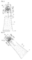
- Figure 3 is a perspective view illustrating a construction of a pumping-type tube container according to a preferred embodiment of the present invention.
- Figure 4 is a view illustrating a use state of a pumping-type tube container according to a preferred embodiment of the present invention.
- the pumping-type tube container comprises a tube body 100, a tube neck 200, a support body 300, a pumping member 400, button part 500, an over cap 600 and a suction pipe 700.
- the tube body 100 is made in a tube shape for containing a content "a” and is equipped with a space in which to store the content "a” and a sealing part 110 the bottom of which is sealed in a state that the content "a” is filled.
- the tube neck 200 is engaged to the top of the tube body 100 and supports the tube body 100 and is preferably hollow in its inner center for the engagement of the pumping member 400.
- the support body 300 is engaged to the tube neck 200 and supports the pumping member 400, an over cap 600 being engaged to its outer side so as to prevent errors in the operation of the button part 500.
- the pumping member 400 is supported by the support body 300 and communicates with the tube body 100 and performs a pumping operation so that the contents held in the tube body 100 can be discharged to the outside.
- the pumping member 400 comprises a pump housing 410 engaged to the hollow portion of the tube neck 200 and equipped with a check valve 411 at its inner lower side, a stem 420 one side of which is engaged to the inner side of the button part 500 and the other side of which is positioned at the inner side of the pump housing 410, the stem 420 moving along with the up and down movements of the button part 500, a piston rod 430 engaged to the bottom of the stem 420, a seal cap 440 which is engaged covering the outer circumferential surface of the piston rod 430 at the bottom of the piston rod 430 and moves along the inner wall of the pump housing 410, and a spring 450 which is engaged covering the surroundings of the stem 420 and provides an upward elastic force for the sake of repeated pumping of the button part 500.
- the button part 500 is engaged to the top of the stem 420 of the pumping member 400 and ascends and descends based on the press of the user and allows the pumping member 400 to perform a pumping operation.
- the over cap 600 covers the support body 300 and the button part 500 and is detachably engaged to the support body 300.
- the over cap 600 is engaged to the support body 300 when in not use, while preventing the errors of the button part 500, and when in use, it separates from the support body 300 and allows the pumping operation to be performed based on the pressurization of the button part 500.
- the suction pipe 700 extends in a downward direction of the pumping member 400 at the bottom of the pumping member 400 for thereby sucking in the contents.
- the suction pipe 700 extends downward from the bottom of the pump housing 410 so that the bottom of the suction pipe 700 is dipped in the contents.
- the suction pipe 700 is configured in such a way that its lower end is dipped in the contents stored in the tube body 100, so the contents "a" can be directly sucked into the interior of the suction pipe 700 during the initial pumping of the pumping member 400, thus minimizing idle operations.
- the suction pipe 700 is formed short and is not dipped in the contents "a", idle operations occur a lot when sucking the contents into the suction pipe 700 during the pumping of the pumping member 400. When it is formed longer, the idle operation also occurs as often as the length of the suction pipe 700 during the pumping of the pumping member 400, so it is most preferred to provide an optimized length of the suction pipe 700.
- the suction pipe 700 is formed with a length long enough to keep the lower end of the suction pipe 700 dipped in the contents so that the contents "a" can be smoothly discharged when using the product in a state that the user slopes the tube body 100 at a certain angle.
- the length "L1" of the lower end of the suction pipe 700 dipped in the contents is shorter than the length "L2" of the suction pipe 700 which is not dipped in the contents, more specifically, the suction pipe 700 has an optimized length, not too long, not too short.
- Figure 5 is a perspective view illustrating a construction of a pumping-type tube container according to another embodiment of the present invention.
- Figure 6 is a view illustrating a use state of a pumping-type tube container according to another embodiment of the present invention.
- the pumping-type tube container comprises an engaging part 412 which supports a suction pipe 700' extending downward from the bottom of the pumping member 400 and sucking the contents .
- the engaging part 412 extends downward from the bottom of the pump housing 410 while covering and supporting the top of the suction pipe 700', so the suction pipe 700' is prevented from moving into the interior of the tube body 100 in the middle of engaging the suction pipe 700'.
Landscapes
- Engineering & Computer Science (AREA)
- Mechanical Engineering (AREA)
- Containers And Packaging Bodies Having A Special Means To Remove Contents (AREA)
- Closures For Containers (AREA)
Abstract
Description
- The present invention relates to a pumping-type tube container, and in particular to a pumping-type tube container which makes it possible to greatly reduce an idle operation during a pumping wok of a pumping member by providing a suction pipe which extends in a downward direction of a pumping member with its end portion dipped in contents, so a user can more comfortably use the products.
- A pumping-type tube container is configured in such a way that a pumping member is disposed at the top of a tube body which contains contents, and the contents can be discharged to the outside through a pumping operation of a pumping member. As shown in
Figures 1 and2 , the above mentioned pumping-type tube container comprises atube body 10 made in a tube type and storing contents, atube neck 20 which is engaged to the top of thetube body 10 and supports thetube body 10 and is equipped with a discharge part through which to discharge contents, asupport body 30 which is engaged to thetube neck 20 while supporting thepumping member 40, and an overcap 60 which covers thepumping member 40 and is detachably engaged to thesupport body 30. - As shown in
Figure 1 , the conventional pumping type tube container has features in that the contents are filled in thetube body 10 in a state that thetube body 10 is made upside down, and theend portion 11 is sealed, and the manufacture is finished. If the sealing work is performed after the contents are filled up to its top, thetube body 10 may overflow, and the overflowing contents may spoil the sealing surface, which makes hard to seal the end portions during the sealing work. - For the above mentioned problems, the contents are filled to the extent that a certain volume can be obtained for the sake of easier sealing work.
- When the container stands upright after the contents are filled, and the sealing work is finished, as shown in
Figure 2 , a space in which the contents are no more filled for the sake of sealing work is formed in thetube body 10. For this configuration, an idle operation occurs during the operation of thepumping member 40 when discharging the contents, so the contents cannot be well discharged. For better discharge of the contents, the user needs to perform more pumping operations, which causes much inconveniences. - Accordingly, the present invention is made so as to improve the above mentioned problems. It is an object of the present invention to provide a pumping-type tube container which makes it possible to greatly reduce an idle operation during a pumping wok of a pumping member by providing a suction pipe which extends in a downward direction of a pumping member with its end portion dipped in contents, so a user can more comfortably use the product.
- To achieve the above object, there is provided a pumping-type tube container formed of a tube body which is formed in a tube shape and stores contents, a tube neck which is engaged to the top of the tube body and supports the tube body, a support body which is engaged to the tube neck and supports the pumping member, and a pumping member which is supported by the support body and performs a pumping operation so that the contents communicating with the tube body and stored in the tube body can be discharged to the outside, comprising:
- a suction pipe which is provided at the bottom of the pumping member and extends in a downward direction of the pumping member and sucks in contents, the lower end portion of the suction pipe being dipped in the contents.
- In addition, to achieve the above object, there is provided a pumping-type tube container formed of a tube body which is formed in a tube shape and stores contents, a tube neck which is engaged to the top of the tube body and supports the tube body, a support body which is engaged to the tube neck and supports the pumping member, and a pumping member which is supported by the support body and performs a pumping operation so that the contents communicating with the tube body and stored in the tube body can be discharged to the outside, comprising:
- an engaging part which is provided at the bottom of the pumping member and extends in a downward direction of the pumping member; and a suction pipe which is engaged to the engaging part and sucks in contents, the lower end portion of the suction pipe being dipped in the contents.
- In addition, the suction pipe has a length long enough for the lower end portion of the suction pipe to dip in the contents in a state that the tube body is obliquely sloped, and the length "L1" of the lower end portion of the suction pipe dipped in the contents is shorter than the length "L2" of the suction pipe which is not dipped in the contents.
- According to the present invention, an idle operation can be minimized during a pumping operation of a pumping member by providing a suction pipe which extends in a downward direction of a pumping member with its end portion dipped in contents, so a user can more comfortably use the product.
- Since the suction pipe dipped in the contents has an optimized length, it is possible to smoothly discharge contents even in a state that the tube body is sloped at a certain angle while saving manufacture materials.
-
-
Figures 1 and2 are cross sectional views illustrating a construction of a conventional pumping type tube container. -
Figure 3 is a perspective view illustrating a construction of a pumping-type tube container according to a preferred embodiment of the present invention. -
Figure 4 is a view illustrating a use state of a pumping-type tube container according to a preferred embodiment of the present invention. -
Figure 5 is a perspective view illustrating a construction of a pumping-type tube container according to another embodiment of the present invention. -
Figure 6 is a view illustrating a use state of a pumping-type tube container according to another embodiment of the present invention. - The present invention will be described with reference to the accompanying drawings. The same reference numerals in each drawing mean the same elements.
-
Figure 3 is a perspective view illustrating a construction of a pumping-type tube container according to a preferred embodiment of the present invention.Figure 4 is a view illustrating a use state of a pumping-type tube container according to a preferred embodiment of the present invention. - As shown in
Figures 3 and 4 , the pumping-type tube container according to a preferred embodiment of the present invention comprises atube body 100, atube neck 200, asupport body 300, apumping member 400,button part 500, an overcap 600 and asuction pipe 700. - The
tube body 100 is made in a tube shape for containing a content "a" and is equipped with a space in which to store the content "a" and asealing part 110 the bottom of which is sealed in a state that the content "a" is filled. - The
tube neck 200 is engaged to the top of thetube body 100 and supports thetube body 100 and is preferably hollow in its inner center for the engagement of thepumping member 400. - The
support body 300 is engaged to thetube neck 200 and supports thepumping member 400, an overcap 600 being engaged to its outer side so as to prevent errors in the operation of thebutton part 500. - The
pumping member 400 is supported by thesupport body 300 and communicates with thetube body 100 and performs a pumping operation so that the contents held in thetube body 100 can be discharged to the outside. Thepumping member 400 comprises apump housing 410 engaged to the hollow portion of thetube neck 200 and equipped with acheck valve 411 at its inner lower side, astem 420 one side of which is engaged to the inner side of thebutton part 500 and the other side of which is positioned at the inner side of thepump housing 410, thestem 420 moving along with the up and down movements of thebutton part 500, apiston rod 430 engaged to the bottom of thestem 420, aseal cap 440 which is engaged covering the outer circumferential surface of thepiston rod 430 at the bottom of thepiston rod 430 and moves along the inner wall of thepump housing 410, and aspring 450 which is engaged covering the surroundings of thestem 420 and provides an upward elastic force for the sake of repeated pumping of thebutton part 500. - The
button part 500 is engaged to the top of thestem 420 of the pumpingmember 400 and ascends and descends based on the press of the user and allows the pumpingmember 400 to perform a pumping operation. - The over
cap 600 covers thesupport body 300 and thebutton part 500 and is detachably engaged to thesupport body 300. The overcap 600 is engaged to thesupport body 300 when in not use, while preventing the errors of thebutton part 500, and when in use, it separates from thesupport body 300 and allows the pumping operation to be performed based on the pressurization of thebutton part 500. - The
suction pipe 700 extends in a downward direction of thepumping member 400 at the bottom of thepumping member 400 for thereby sucking in the contents. In the present invention, thesuction pipe 700 extends downward from the bottom of thepump housing 410 so that the bottom of thesuction pipe 700 is dipped in the contents. - The
suction pipe 700 is configured in such a way that its lower end is dipped in the contents stored in thetube body 100, so the contents "a" can be directly sucked into the interior of thesuction pipe 700 during the initial pumping of thepumping member 400, thus minimizing idle operations. - The
suction pipe 700 is formed short and is not dipped in the contents "a", idle operations occur a lot when sucking the contents into thesuction pipe 700 during the pumping of thepumping member 400. When it is formed longer, the idle operation also occurs as often as the length of thesuction pipe 700 during the pumping of thepumping member 400, so it is most preferred to provide an optimized length of thesuction pipe 700. - As shown in
Figure 4 , thesuction pipe 700 is formed with a length long enough to keep the lower end of thesuction pipe 700 dipped in the contents so that the contents "a" can be smoothly discharged when using the product in a state that the user slopes thetube body 100 at a certain angle. - As shown in
Figure 3 , it is preferred that the length "L1" of the lower end of thesuction pipe 700 dipped in the contents is shorter than the length "L2" of thesuction pipe 700 which is not dipped in the contents, more specifically, thesuction pipe 700 has an optimized length, not too long, not too short. - The pumping-type tube container according to another embodiment of the present invention will be described with reference to
Figures 5 and 6 . -
Figure 5 is a perspective view illustrating a construction of a pumping-type tube container according to another embodiment of the present invention.Figure 6 is a view illustrating a use state of a pumping-type tube container according to another embodiment of the present invention. - As shown in
Figures 5 and 6 , the pumping-type tube container according to another embodiment of the present invention comprises anengaging part 412 which supports asuction pipe 700' extending downward from the bottom of thepumping member 400 and sucking the contents . Theengaging part 412 extends downward from the bottom of thepump housing 410 while covering and supporting the top of thesuction pipe 700', so thesuction pipe 700' is prevented from moving into the interior of thetube body 100 in the middle of engaging thesuction pipe 700'. - Since the remaining constructions are same as the earlier described constructions of the embodiments of the present invention, the detailed descriptions will be omitted.
- As the present invention may be embodied in several forms without departing from the spirit or essential characteristics thereof, it should also be understood that the above-described examples are not limited by any of the details of the foregoing description, unless otherwise specified, but rather should be construed broadly within its spirit and scope as defined in the appended claims, and therefore all changes and modifications that fall within the meets and bounds of the claims, or equivalences of such meets and bounds are therefore intended to be embraced by the appended claims.
Claims (3)
- A pumping-type tube container formed of a tube body which is formed in a tube shape and stores contents, a tube neck which is engaged to the top of the tube body and supports the tube body, a support body which is engaged to the tube neck and supports the pumping member, and a pumping member which is supported by the support body and performs a pumping operation so that the contents communicating with the tube body and stored in the tube body can be discharged to the outside, comprising:a suction pipe which is provided at the bottom of the pumping member and extends in a downward direction of the pumping member and sucks in contents, the lower end portion of the suction pipe being dipped in the contents.
- A pumping-type tube container formed of a tube body which is formed in a tube shape and stores contents, a tube neck which is engaged to the top of the tube body and supports the tube body, a support body which is engaged to the tube neck and supports the pumping member, and a pumping member which is supported by the support body and performs a pumping operation so that the contents communicating with the tube body and stored in the tube body can be discharged to the outside, comprising:an engaging part which is provided at the bottom of the pumping member and extends in a downward direction of the pumping member; anda suction pipe which is engaged to the engaging part and sucks in contents, the lower end portion of the suction pipe being dipped in the contents.
- The container of either claim 1 or claim 2, wherein the suction pipe has a length long enough for the lower end portion of the suction pipe to dip in the contents in a state that the tube body is obliquely sloped, and the length "L1" of the lower end portion of the suction pipe dipped in the contents is shorter than the length "L2" of the suction pipe which is not dipped in the contents.
Applications Claiming Priority (2)
| Application Number | Priority Date | Filing Date | Title |
|---|---|---|---|
| KR1020110098868A KR101367635B1 (en) | 2011-09-29 | 2011-09-29 | Tube vessel of pumping type |
| PCT/KR2012/007429 WO2013048044A2 (en) | 2011-09-29 | 2012-09-18 | Pumping-type tube container |
Publications (2)
| Publication Number | Publication Date |
|---|---|
| EP2762420A2 true EP2762420A2 (en) | 2014-08-06 |
| EP2762420A4 EP2762420A4 (en) | 2015-07-29 |
Family
ID=47996580
Family Applications (1)
| Application Number | Title | Priority Date | Filing Date |
|---|---|---|---|
| EP12835919.7A Withdrawn EP2762420A4 (en) | 2011-09-29 | 2012-09-18 | Pumping-type tube container |
Country Status (6)
| Country | Link |
|---|---|
| US (1) | US20140231465A1 (en) |
| EP (1) | EP2762420A4 (en) |
| JP (1) | JP6156704B2 (en) |
| KR (1) | KR101367635B1 (en) |
| CN (1) | CN103813966B (en) |
| WO (1) | WO2013048044A2 (en) |
Cited By (1)
| Publication number | Priority date | Publication date | Assignee | Title |
|---|---|---|---|---|
| CN106742626A (en) * | 2016-11-11 | 2017-05-31 | 陈海军 | A kind of toothpaste tube |
Families Citing this family (1)
| Publication number | Priority date | Publication date | Assignee | Title |
|---|---|---|---|---|
| KR102496967B1 (en) * | 2021-10-13 | 2023-02-07 | (주)연우 | Container |
Family Cites Families (11)
| Publication number | Priority date | Publication date | Assignee | Title |
|---|---|---|---|---|
| US4018364A (en) * | 1975-04-03 | 1977-04-19 | Hershel Earl Wright | Foam dispensing device |
| FR2646408B1 (en) * | 1989-04-28 | 1991-08-30 | Sofab | PACKAGING WITH INTEGRATED DISPENSER |
| FR2658793B1 (en) | 1990-02-28 | 1992-06-19 | Oreal | DISPENSING ASSEMBLY OF A PRODUCT IN WHICH THE PRODUCT TO BE DISPENSED IS CONTAINED IN A FLEXIBLE POCKET. |
| CN2066015U (en) * | 1990-03-23 | 1990-11-21 | 苏正原 | Nozzle valve body |
| US5183185A (en) * | 1991-02-14 | 1993-02-02 | Ecopac, L. P. | Mechanically pressurized dispenser system |
| JP2575622Y2 (en) * | 1991-09-09 | 1998-07-02 | 釜屋化学工業株式会社 | Tube container |
| EP1873076B1 (en) * | 1994-11-17 | 2012-01-25 | Yoshino Kogyosho Co., Ltd. | Container with pump for discharging bubbles |
| US5697530A (en) * | 1996-01-29 | 1997-12-16 | Monturas, S.A. | Precompression pump sprayer |
| KR100481617B1 (en) * | 2001-12-20 | 2005-04-08 | 우륭유 | Atomizer With a Bellows-Shaped Container Body |
| KR20060128600A (en) * | 2005-06-09 | 2006-12-14 | 고재덕 | How to Store Liquid Toothpaste in a Container |
| FR2930178B1 (en) * | 2008-04-22 | 2010-06-11 | Rexam Dispensing Sys | BOTTLE COMPRISING A DISTRIBUTION BELLOW. |
-
2011
- 2011-09-29 KR KR1020110098868A patent/KR101367635B1/en active Active
-
2012
- 2012-09-18 US US14/342,640 patent/US20140231465A1/en not_active Abandoned
- 2012-09-18 EP EP12835919.7A patent/EP2762420A4/en not_active Withdrawn
- 2012-09-18 JP JP2014533188A patent/JP6156704B2/en active Active
- 2012-09-18 CN CN201280044158.8A patent/CN103813966B/en active Active
- 2012-09-18 WO PCT/KR2012/007429 patent/WO2013048044A2/en not_active Ceased
Cited By (2)
| Publication number | Priority date | Publication date | Assignee | Title |
|---|---|---|---|---|
| CN106742626A (en) * | 2016-11-11 | 2017-05-31 | 陈海军 | A kind of toothpaste tube |
| CN106742626B (en) * | 2016-11-11 | 2018-08-07 | 陈海军 | A kind of toothpaste tube |
Also Published As
| Publication number | Publication date |
|---|---|
| WO2013048044A2 (en) | 2013-04-04 |
| CN103813966A (en) | 2014-05-21 |
| CN103813966B (en) | 2015-10-14 |
| JP2014531370A (en) | 2014-11-27 |
| JP6156704B2 (en) | 2017-07-05 |
| KR101367635B1 (en) | 2014-02-27 |
| US20140231465A1 (en) | 2014-08-21 |
| KR20130034797A (en) | 2013-04-08 |
| EP2762420A4 (en) | 2015-07-29 |
| WO2013048044A3 (en) | 2013-05-23 |
Similar Documents
| Publication | Publication Date | Title |
|---|---|---|
| US20150108171A1 (en) | Cap-integrated pumping type cosmetic container | |
| US9434526B2 (en) | Mixing container for different contents | |
| US9427064B2 (en) | Liquid dropper allowing quantitative withdrawal, and a cosmetic container equipped with the same | |
| US8627987B2 (en) | Container with elevating inner wall | |
| US9375740B2 (en) | Dispenser pump button | |
| CN102333708B (en) | Synthetic resin container with reversed and folded bottom wall | |
| US20170238675A1 (en) | Cream type cosmetic container | |
| US20170181523A1 (en) | Liquid Lipstick Container | |
| US20140231465A1 (en) | Pumping-type tube container | |
| CN104781015B (en) | Fluid product tank | |
| EP2859957B1 (en) | Cap-integrated pumping type cosmetic container | |
| US20160022096A1 (en) | Saver bottle | |
| EP3025613A1 (en) | Piston structure of pumping-type cosmetic container | |
| JP2018510817A5 (en) | ||
| JP2020152406A5 (en) | ||
| KR20160029434A (en) | Pump type container with caean and empty structure for toothpaste | |
| KR102473311B1 (en) | cosmetic container | |
| KR101467217B1 (en) | Dispenser vessel with a structure of preventing liquid leakage | |
| JP6859021B2 (en) | Container with cap | |
| JP5883666B2 (en) | Cup type container | |
| JP3973896B2 (en) | Container with pump discharger | |
| KR101713048B1 (en) | The container controlling the quantity of its content | |
| JP5071936B2 (en) | Discharge container | |
| JP5115977B2 (en) | Pill container | |
| JP3111572U (en) | Container for goods |
Legal Events
| Date | Code | Title | Description |
|---|---|---|---|
| PUAI | Public reference made under article 153(3) epc to a published international application that has entered the european phase |
Free format text: ORIGINAL CODE: 0009012 |
|
| 17P | Request for examination filed |
Effective date: 20140326 |
|
| AK | Designated contracting states |
Kind code of ref document: A2 Designated state(s): AL AT BE BG CH CY CZ DE DK EE ES FI FR GB GR HR HU IE IS IT LI LT LU LV MC MK MT NL NO PL PT RO RS SE SI SK SM TR |
|
| DAX | Request for extension of the european patent (deleted) | ||
| A4 | Supplementary search report drawn up and despatched |
Effective date: 20150629 |
|
| RIC1 | Information provided on ipc code assigned before grant |
Ipc: B05B 15/00 20060101AFI20150622BHEP Ipc: B05B 11/00 20060101ALI20150622BHEP |
|
| STAA | Information on the status of an ep patent application or granted ep patent |
Free format text: STATUS: THE APPLICATION IS DEEMED TO BE WITHDRAWN |
|
| 18D | Application deemed to be withdrawn |
Effective date: 20170401 |