EP2762406A1 - Pneumatically augmented elastomeric damper for improved spring rate tuning - Google Patents
Pneumatically augmented elastomeric damper for improved spring rate tuning Download PDFInfo
- Publication number
- EP2762406A1 EP2762406A1 EP20130163188 EP13163188A EP2762406A1 EP 2762406 A1 EP2762406 A1 EP 2762406A1 EP 20130163188 EP20130163188 EP 20130163188 EP 13163188 A EP13163188 A EP 13163188A EP 2762406 A1 EP2762406 A1 EP 2762406A1
- Authority
- EP
- European Patent Office
- Prior art keywords
- chamber
- damper
- elastomeric material
- aircraft
- gas
- Prior art date
- Legal status (The legal status is an assumption and is not a legal conclusion. Google has not performed a legal analysis and makes no representation as to the accuracy of the status listed.)
- Granted
Links
Images



Classifications
-
- F—MECHANICAL ENGINEERING; LIGHTING; HEATING; WEAPONS; BLASTING
- F16—ENGINEERING ELEMENTS AND UNITS; GENERAL MEASURES FOR PRODUCING AND MAINTAINING EFFECTIVE FUNCTIONING OF MACHINES OR INSTALLATIONS; THERMAL INSULATION IN GENERAL
- F16F—SPRINGS; SHOCK-ABSORBERS; MEANS FOR DAMPING VIBRATION
- F16F13/00—Units comprising springs of the non-fluid type as well as vibration-dampers, shock-absorbers, or fluid springs
- F16F13/04—Units comprising springs of the non-fluid type as well as vibration-dampers, shock-absorbers, or fluid springs comprising both a plastics spring and a damper, e.g. a friction damper
- F16F13/26—Units comprising springs of the non-fluid type as well as vibration-dampers, shock-absorbers, or fluid springs comprising both a plastics spring and a damper, e.g. a friction damper characterised by adjusting or regulating devices responsive to exterior conditions
-
- B—PERFORMING OPERATIONS; TRANSPORTING
- B64—AIRCRAFT; AVIATION; COSMONAUTICS
- B64C—AEROPLANES; HELICOPTERS
- B64C27/00—Rotorcraft; Rotors peculiar thereto
- B64C27/001—Vibration damping devices
-
- F—MECHANICAL ENGINEERING; LIGHTING; HEATING; WEAPONS; BLASTING
- F16—ENGINEERING ELEMENTS AND UNITS; GENERAL MEASURES FOR PRODUCING AND MAINTAINING EFFECTIVE FUNCTIONING OF MACHINES OR INSTALLATIONS; THERMAL INSULATION IN GENERAL
- F16F—SPRINGS; SHOCK-ABSORBERS; MEANS FOR DAMPING VIBRATION
- F16F13/00—Units comprising springs of the non-fluid type as well as vibration-dampers, shock-absorbers, or fluid springs
- F16F13/04—Units comprising springs of the non-fluid type as well as vibration-dampers, shock-absorbers, or fluid springs comprising both a plastics spring and a damper, e.g. a friction damper
- F16F13/06—Units comprising springs of the non-fluid type as well as vibration-dampers, shock-absorbers, or fluid springs comprising both a plastics spring and a damper, e.g. a friction damper the damper being a fluid damper, e.g. the plastics spring not forming a part of the wall of the fluid chamber of the damper
-
- B—PERFORMING OPERATIONS; TRANSPORTING
- B64—AIRCRAFT; AVIATION; COSMONAUTICS
- B64C—AEROPLANES; HELICOPTERS
- B64C27/00—Rotorcraft; Rotors peculiar thereto
- B64C27/001—Vibration damping devices
- B64C2027/003—Vibration damping devices mounted on rotor hub, e.g. a rotary force generator
Definitions
- the present application relates generally to dampers, and more specifically, to adjustable aircraft dampers.
- Dampers are well known in the aircraft industry for effectively compensating for undesired forces during flight.
- an aircraft utilizes a plurality of dampers for a rotor system, wherein undesired forces created by the rotor blades are dampened, resulting in optimal flight conditions.
- a common problem associated with conventional dampers is the inability to selectively change the damper spring rate during flight.
- an aircraft damper is subject to temperature changes as the aircraft increases elevation, which in turn affects the elastic properties of the elastomeric material disposed within the damper, resulting in different spring rates during flight.
- the damper system and method of the present application overcome the above-listed problems commonly associated with conventional dampers.
- the damper system is provided with an adjustable damper, wherein depending on desired flight conditions, the damper system adjusts the damper spring rate such that optimal flight conditions are achieved.
- the damper system is capable of achieving such results by regulating, either via gas or fluid, at least one chamber disposed within the damper and operably associated with the elastomeric material therein. Further detailed description of these features is provided below and illustrated in the accompanying drawings.
- FIG. 1 depicts an aircraft 101 in accordance with a preferred embodiment of the present application.
- aircraft 101 is a helicopter having a fuselage 103 and a rotor system 105 carried thereon.
- a plurality of rotor blades 107 is operably associated with rotor system 105 for creating flight.
- damper systems 109 are operably associated with rotor system 105, for example a rotor swashplate 111 or other devices of the rotor system.
- damper system 109 is configured to dampen forces created by the rotor system 105 during flight; however, it will be appreciated that damper system 109 could also be utilized with different devices of the aircraft or vehicles that utilize dampers in accordance with the present application.
- FIG. 2 depicts a partial cross-sectional perspective view of a damper 201 of damper system 109.
- Damper 201 comprises a housing 203 having a cavity 204 with an elastomeric material 205 disposed therein.
- elastomeric material 205 fixedly attaches to an inner surface 207 of housing 203, thus preventing sliding movement of the elastomeric material relative to the inner surface during use.
- Elastomeric material 205 receives a rod 209 that in turn attaches to a rod connector 211.
- a second rod connector 213 is shown rigidly attached to the opposing end of housing 203.
- the rod connectors couple to one or more devices operably associated with rotor system 105, for example, the swashplate and/or yoke.
- forces "F" are exerted on damper 201, which in turn are dampened via the elastomeric material 205 disposed within housing 203.
- damper 201 is utilizing at least one chamber associated with elastomeric material 205 for adjusting the spring rate.
- two chambers are utilized: a first chamber 215 formed by inner surface 207 and a first end 217 of elastomeric material 205; and, a second opposing chamber 219 formed by inner surface 207 and a second end 221 of elastomeric material 205.
- the exemplary embodiment utilizes two chambers; however, it will be appreciated that alternative embodiments could use more or less chambers for regulating the spring rate in accordance with the features discussed herein.
- the ports pass through the thickness of housing 203 and provide attachment means for conduits in gas/fluid communication with a reservoir.
- gas or fluid is channeled from the reservoir and passes through the ports and thereafter to the chambers.
- the quantity of gas/fluid entering the chamber changes the pressure therein, which in turn is exerted against the elastomeric material, thereby restricting movement of the movement elastomeric material. This process allows for real time adjustment of the damper spring rate.
- gas is utilized to operate the damper system; however, alternative embodiments could utilize incompressible fluids and the reservoirs would not reach full capacity else hydraulic lock could occur.
- One or more optional shims 227 are disposed with elastomeric material 205 and are utilized to increasing rigidity of the elastomeric material along with other desired features.
- FIGS. 3 and 4 depict side views of two different embodiments of damper system 109, which are substantially similar in form and function to each other, and share one or more of the features discussed herein.
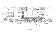
- FIG. 3 depicts a side view of damper system 301 operably associated with damper 201.
- System 301 includes two gas/fluid reservoirs: a first reservoir 303 in communication with chamber 215 via a conduit 305; and, a second reservoir 307 in communication with chamber 219 via a conduit 309.
- two reservoirs are utilized to provide the same or different gas/fluid pressures within the chambers. It will also be appreciated that the system is adapted to create both negative and positive pressures in either chamber, all depending on the desired use.
- valves 311 and 313 configured to regulate the flow of gas/fluid channeled to the chambers.
- a first driver 315 is operably associated with first reservoir 303, and likewise, a second driver 317 is operably associated with second reservoir 307. Both drivers 315 and 317 are configured to drive the gas/fluid carried within the reservoir to the chambers.
- the drivers are pneumatic systems; however, other driver systems such as a gear system are also contemplated in the alternative embodiments.
- System 301 further comprises a control system 319 operably associated with the gas/fluid reservoirs and valves, as depicted with dashed lines.
- Control system 319 monitors the spring rate of damper 201 via a sensor 321 and thereafter regulates the spring rate by adjusting the drivers and/or valves such that a desired spring rate is achieved.
- system 301 is capable of obtaining a desired spring rate in real time as flight conditions or aircraft performance change.
- control system 319 is autonomously controlled; however, alternative embodiments could include a control system that is manually controlled by the operator.
- FIG. 4 is a cross-sectional side view of damper system 401.
- Damper system 401 is substantially similar in form and function to system 301.
- a single gas/fluid reservoir is in communication with both chambers, and it is contemplated having the same pressure in both chambers.
- the exemplary embodiment also allows for both chambers to be in gas/fluid communication with each other.
- System 401 includes a gas/fluid reservoir 403 in communication with both chambers 215 and 219 via a conduit 405.
- a valve 407 configured to regulate the flow of gas/fluid from the reservoir to the chambers.
- a driver 409 is operably associated with reservoir 403 for driving the gas/fluid carried within the reservoir to the chambers.
- the drivers are pneumatic systems; however, other driver systems such as a gear system are also contemplated in the alternative embodiments.
- System 401 further comprises a control system 411 operably associated with the gas/fluid reservoir and valve, as depicted with dashed lines.
- control system 411 monitors the spring rate of damper 201 via a sensor 413 and thereafter adjusts the drivers and valves such that a desired pressure within the chambers is achieved to adjust the spring rate.
- system 401 is capable of obtaining a desired spring rate in real time as flight conditions change.
- Alternative embodiments could also include a single gas/fluid reservoir in communication with both chambers, but configured such that different pressures are created in each chamber.
Landscapes
- Engineering & Computer Science (AREA)
- General Engineering & Computer Science (AREA)
- Mechanical Engineering (AREA)
- Aviation & Aerospace Engineering (AREA)
- Vibration Prevention Devices (AREA)
- Fluid-Damping Devices (AREA)
Abstract
Description
- The present application relates generally to dampers, and more specifically, to adjustable aircraft dampers.
- Dampers are well known in the aircraft industry for effectively compensating for undesired forces during flight. In some embodiments, an aircraft utilizes a plurality of dampers for a rotor system, wherein undesired forces created by the rotor blades are dampened, resulting in optimal flight conditions.
- A common problem associated with conventional dampers is the inability to selectively change the damper spring rate during flight. For example, an aircraft damper is subject to temperature changes as the aircraft increases elevation, which in turn affects the elastic properties of the elastomeric material disposed within the damper, resulting in different spring rates during flight. These undesired features greatly reduce the damper efficiency, thus potentially harming the flight characteristics of the aircraft during flight.
- Although significant developments in dampers have been made, many shortcomings remain.
- The novel features believed characteristic of the embodiments of the present application are set forth in the appended claims. However, the embodiments themselves, as well as a preferred mode of use, and further objectives and advantages thereof, will best be understood by reference to the following detailed description when read in conjunction with the accompanying drawings, wherein:
-
FIG. 1 is a side view of an aircraft according to the preferred embodiment of the present application; -
FIG. 2 is a perspective view of a damper ofFIG. 1 ; -
FIG. 3 is a cross-sectional side view a damper system ofFIG. 1 ; and -
FIG. 4 is an alternative embodiment of the damper system ofFIG. 3 . - While the system and method of the present application is susceptible to various modifications and alternative forms, specific embodiments thereof have been shown by way of example in the drawings and are herein described in detail. It should be understood, however, that the description herein of specific embodiments is not intended to limit the invention to the particular embodiment disclosed, but on the contrary, the intention is to cover all modifications, equivalents, and alternatives falling within the spirit and scope of the process of the present application as defined by the appended claims.
- Illustrative embodiments of the system and method are provided below. It will of course be appreciated that in the development of any actual embodiment, numerous implementation-specific decisions will be made to achieve the developer's specific goals, such as compliance with system-related and business-related constraints, which will vary from one implementation to another. Moreover, it will be appreciated that such a development effort might be complex and time-consuming, but would nevertheless be a routine undertaking for those of ordinary skill in the art having the benefit of this disclosure.
- The damper system and method of the present application overcome the above-listed problems commonly associated with conventional dampers. Specifically, the damper system is provided with an adjustable damper, wherein depending on desired flight conditions, the damper system adjusts the damper spring rate such that optimal flight conditions are achieved. The damper system is capable of achieving such results by regulating, either via gas or fluid, at least one chamber disposed within the damper and operably associated with the elastomeric material therein. Further detailed description of these features is provided below and illustrated in the accompanying drawings.
- The system and method of the present application will be understood, both as to its structure and operation, from the accompanying drawings, taken in conjunction with the accompanying description. Several embodiments of the system are presented herein. It should be understood that various components, parts, and features of the different embodiments may be combined together and/or interchanged with one another, all of which are within the scope of the present application, even though not all variations and particular embodiments are shown in the drawings. It should also be understood that the mixing and matching of features, elements, and/or functions between various embodiments is expressly contemplated herein so that one of ordinary skill in the art would appreciate from this disclosure that the features, elements, and/or functions of one embodiment may be incorporated into another embodiment as appropriate, unless described otherwise.
- Referring now to the drawings wherein like reference characters identify corresponding or similar elements throughout the several views,
FIG. 1 depicts anaircraft 101 in accordance with a preferred embodiment of the present application. In the exemplary embodiment,aircraft 101 is a helicopter having afuselage 103 and arotor system 105 carried thereon. A plurality ofrotor blades 107 is operably associated withrotor system 105 for creating flight. - As depicted, one or
more damper systems 109 are operably associated withrotor system 105, for example arotor swashplate 111 or other devices of the rotor system. In the contemplated embodiment,damper system 109 is configured to dampen forces created by therotor system 105 during flight; however, it will be appreciated thatdamper system 109 could also be utilized with different devices of the aircraft or vehicles that utilize dampers in accordance with the present application. -
FIG. 2 depicts a partial cross-sectional perspective view of adamper 201 ofdamper system 109. Damper 201 comprises ahousing 203 having acavity 204 with anelastomeric material 205 disposed therein. In the contemplated embodiment,elastomeric material 205 fixedly attaches to aninner surface 207 ofhousing 203, thus preventing sliding movement of the elastomeric material relative to the inner surface during use. -
Elastomeric material 205 receives arod 209 that in turn attaches to arod connector 211. Asecond rod connector 213 is shown rigidly attached to the opposing end ofhousing 203. In the contemplated embodiment, the rod connectors couple to one or more devices operably associated withrotor system 105, for example, the swashplate and/or yoke. During operation, forces "F", as depicted with an arrow, are exerted ondamper 201, which in turn are dampened via theelastomeric material 205 disposed withinhousing 203. - One of the unique features believed characteristic of
damper 201 is utilizing at least one chamber associated withelastomeric material 205 for adjusting the spring rate. In the exemplary embodiment, two chambers are utilized: afirst chamber 215 formed byinner surface 207 and afirst end 217 ofelastomeric material 205; and, a secondopposing chamber 219 formed byinner surface 207 and asecond end 221 ofelastomeric material 205. The exemplary embodiment utilizes two chambers; however, it will be appreciated that alternative embodiments could use more or less chambers for regulating the spring rate in accordance with the features discussed herein. - In gas/fluid communication with
first chamber 215 is afirst port 223, and asecond port 225 in gas/fluid communication withsecond chamber 219. The ports pass through the thickness ofhousing 203 and provide attachment means for conduits in gas/fluid communication with a reservoir. During operation, either gas or fluid is channeled from the reservoir and passes through the ports and thereafter to the chambers. The quantity of gas/fluid entering the chamber changes the pressure therein, which in turn is exerted against the elastomeric material, thereby restricting movement of the movement elastomeric material. This process allows for real time adjustment of the damper spring rate. - In the contemplated embodiment, gas is utilized to operate the damper system; however, alternative embodiments could utilize incompressible fluids and the reservoirs would not reach full capacity else hydraulic lock could occur.
- One or more
optional shims 227, preferably composed of a metallic material, are disposed withelastomeric material 205 and are utilized to increasing rigidity of the elastomeric material along with other desired features. -
FIGS. 3 and4 depict side views of two different embodiments ofdamper system 109, which are substantially similar in form and function to each other, and share one or more of the features discussed herein. -
FIG. 3 depicts a side view ofdamper system 301 operably associated withdamper 201.System 301 includes two gas/fluid reservoirs: afirst reservoir 303 in communication withchamber 215 via aconduit 305; and, asecond reservoir 307 in communication withchamber 219 via aconduit 309. In the exemplary embodiment, two reservoirs are utilized to provide the same or different gas/fluid pressures within the chambers. It will also be appreciated that the system is adapted to create both negative and positive pressures in either chamber, all depending on the desired use. - In gas/fluid communication with
conduits respective valves - A
first driver 315 is operably associated withfirst reservoir 303, and likewise, asecond driver 317 is operably associated withsecond reservoir 307. Bothdrivers -
System 301 further comprises acontrol system 319 operably associated with the gas/fluid reservoirs and valves, as depicted with dashed lines.Control system 319 monitors the spring rate ofdamper 201 via asensor 321 and thereafter regulates the spring rate by adjusting the drivers and/or valves such that a desired spring rate is achieved. Thus,system 301 is capable of obtaining a desired spring rate in real time as flight conditions or aircraft performance change. - In the contemplated embodiment,
control system 319 is autonomously controlled; however, alternative embodiments could include a control system that is manually controlled by the operator. - It will be appreciated that alternative embodiments could also solely utilize the drivers to regulate the gas/fluid pressure within the chambers. These embodiments would eliminate the need for valves. It is also contemplated utilizing a single driver to regulate both reservoirs, thereby eliminating redundancy.
-
FIG. 4 is a cross-sectional side view ofdamper system 401.Damper system 401 is substantially similar in form and function tosystem 301. In this embodiment, a single gas/fluid reservoir is in communication with both chambers, and it is contemplated having the same pressure in both chambers. The exemplary embodiment also allows for both chambers to be in gas/fluid communication with each other. -
System 401 includes a gas/fluid reservoir 403 in communication with bothchambers conduit 405. In gas/fluid communication withconduit 405 is avalve 407 configured to regulate the flow of gas/fluid from the reservoir to the chambers. Adriver 409 is operably associated withreservoir 403 for driving the gas/fluid carried within the reservoir to the chambers. In the preferred embodiment, the drivers are pneumatic systems; however, other driver systems such as a gear system are also contemplated in the alternative embodiments. -
System 401 further comprises acontrol system 411 operably associated with the gas/fluid reservoir and valve, as depicted with dashed lines. In particular,control system 411 monitors the spring rate ofdamper 201 via asensor 413 and thereafter adjusts the drivers and valves such that a desired pressure within the chambers is achieved to adjust the spring rate. Thus,system 401 is capable of obtaining a desired spring rate in real time as flight conditions change. - Alternative embodiments could also include a single gas/fluid reservoir in communication with both chambers, but configured such that different pressures are created in each chamber.
- Although shown operably associated with two chambers, it will be appreciated that the features of
systems - Although particular step sequences of a method to change the spring rate are shown, described, and claimed, it should be understood that steps may be performed in any order, separated or combined unless otherwise indicated and will still benefit from the present disclosure.
- It is apparent that a system and method with significant advantages has been described and illustrated. The particular embodiments disclosed above are illustrative only, as the embodiments may be modified and practiced in different but equivalent manners apparent to those skilled in the art having the benefit of the teachings herein. It is therefore evident that the particular embodiments disclosed above may be altered or modified, and all such variations are considered within the scope and spirit of the application. Accordingly, the protection sought herein is as set forth in the description. Although the present embodiments are shown above, they are not limited to just these embodiments, but are amenable to various changes and modifications without departing from the spirit thereof.
Claims (18)
- A damper system, comprising:a damper, having:a housing having an inner surface that forms a cavity;an elastomeric material disposed within the cavity and fixedly attached to the inner surface of the housing, the elastomeric material being configured to receive an attachment rod end; anda first chamber formed by a first end of the elastomeric material and the inner surface of the housing, the first chamber being configured to restrict movement of the elastomeric material by regulating the pressure therein;wherein restricting movement of the elastomeric material changes a spring rate of the damper.
- An aircraft rotor system of an aircraft, comprising:a yoke having a plurality of rotor blades attached thereto; anda damper system operably associated with the rotor disk,wherein the rotor system comprises a damper system according to claim 1.
- An aircraft rotor system of an aircraft, comprising:a yoke having a plurality of rotor blades attached thereto; anda damper system operably associated with the rotor disk, the damper system having:a damper, having:a housing having an inner surface that forms a cavity;an elastomeric material disposed within the cavity and fixedly attached to the inner surface of the housing, the elastomeric material being configured to receive an attachment rod end; anda first chamber formed by a first end of the elastomeric material and the inner surface of the housing, the first chamber being configured to restrict movement of the elastomeric material by regulating the pressure therein.
- The damper system of claim 1 or the aircraft system of claim 2 or claim 3, further comprising:a port in communication with the first chamber; anda reservoir in communication with the port.
- The damper system or aircraft system of claim 4, wherein the reservoir is a gas reservoir in gaseous communication with the first chamber via the port; and
wherein pressure from the gas entering into the first chamber restricts movement of the elastomeric material that in turn changes the spring rate of the damp er. - The damper system or aircraft system of claim 5, further comprising:a valve; anda control system operably associated with the valve;wherein the control system regulates the amount of gas received within the first chamber via the valve.
- The damper system or aircraft system of claim 1 or claim 2 or claim 3, or of any preceding claim, the damper further comprising:a second chamber formed by a second opposing end of the elastomeric material and the inner surface of the housing, the second chamber being configured to restrict movement of the elastomeric material by regulating the pressure therein.
- The damper system or aircraft system of claim 7, wherein the first chamber is in communication with the second chamber.
- The damper system or aircraft system of claim 7 or of claim 8, wherein the first chamber creates a first pressure and the second chamber creates a second pressure; and
wherein the first pressure and the second pressure are not equal. - The damper system or aircraft system of claim 7 or of claim 8 or of claim 9, further comprising:a port in communication with the second chamber; anda reservoir in communication with the port.
- The damper system or aircraft system of claim 10, wherein the reservoir is a gas reservoir in gaseous communication with the first chamber via the port; and
wherein pressure from the gas entering into the second chamber restricts movement of the elastomeric material that in turn changes the spring rate of the damp er. - The damper system or aircraft system of claim 11, further comprising:a valve; anda control system operably associated with the valve;wherein the control system regulates the amount of gas received within the second chamber via the valve.
- The damper system or aircraft system of claim 7, or any claim dependent directly or indirectly from claim 7, further comprising:a gas reservoir in gaseous communication with both the first chamber and the second chamber; anda control system operably associated with the gas reservoir and configured to regulate the amount of gas in each of the first chamber and the second chamber; wherein regulating the amount of gas in each the first chamber and second chamber changes the spring rate of the damper.
- The damper system or aircraft system of claim 7, or any claim dependent directly or indirectly from claim 7, further comprising:a fluid reservoir in fluid communication with both the first chamber and the second chamber; anda control system operably associated with the fluid reservoir and configured to regulate the amount of fluid in each of the first chamber and the second chamber; wherein regulating the amount of fluid in each the first chamber and second chamber changes the spring rate of the damper; orthe damper system or aircraft system according to claim 7 or claim 9, or the aircraft or damper system of any preceding claim that depends from claim 7 or claim 9, the system further comprising:a gas reservoir in gaseous communication with both the first chamber and the second chamber; anda control system operably associated with the gas reservoir and configured to regulate the amount of gas in each of the first chamber and the second chamber;wherein regulating the amount of gas in each the first chamber and second chamber changes the spring rate of the damper.
- The damper system of claim 1 or aircraft system of claim 2 or claim 3, or the aircraft system or damper system of any preceding claim, further comprising:a plurality of longitudinal shims disposed within the elastomeric material.
- A method to change a spring rate of a damper in real time, comprising:forming a first chamber in communication with an elastomeric material disposed within a housing of the damper;restricting movement of the elastomeric material by regulating the pressure within the first chamber;wherein regulating and restricting movement to the elastomeric material via the first chamber changes the spring rate of the damper in real time.
- The method of claim 16, further comprising:forming a second chamber in communication with the elastomeric material disposed within the housing of the damper; andrestricting movement of the elastomeric material by regulating the pressure within the second chamber;wherein the second chamber is positioned at an opposing end of the elastomeric material.
- The method of claim 16 or of claim 17, further comprising:monitoring pressure of the first chamber with a control system; andregulating pressure of the first chamber via the control system.
Applications Claiming Priority (1)
| Application Number | Priority Date | Filing Date | Title |
|---|---|---|---|
| US13/758,488 US9004466B2 (en) | 2013-02-04 | 2013-02-04 | Pneumatically augmented elastomeric damper for improved spring rate tuning |
Publications (2)
| Publication Number | Publication Date |
|---|---|
| EP2762406A1 true EP2762406A1 (en) | 2014-08-06 |
| EP2762406B1 EP2762406B1 (en) | 2015-04-08 |
Family
ID=48049894
Family Applications (1)
| Application Number | Title | Priority Date | Filing Date |
|---|---|---|---|
| EP20130163188 Active EP2762406B1 (en) | 2013-02-04 | 2013-04-10 | Pneumatically augmented elastomeric damper for improved spring rate tuning |
Country Status (4)
| Country | Link |
|---|---|
| US (1) | US9004466B2 (en) |
| EP (1) | EP2762406B1 (en) |
| CN (1) | CN103967996B (en) |
| CA (1) | CA2841413C (en) |
Families Citing this family (8)
| Publication number | Priority date | Publication date | Assignee | Title |
|---|---|---|---|---|
| CN105508488B (en) * | 2015-12-18 | 2017-12-08 | 南京航空航天大学 | A kind of compound Helicopter Main subtracts cycle strut |
| EP3336485B1 (en) | 2016-12-15 | 2020-09-23 | Safran Landing Systems UK Limited | Aircraft assembly including deflection sensor |
| WO2019143764A1 (en) | 2018-01-17 | 2019-07-25 | Adams Rite Aerospace Inc. | Shock absorber configured with a deformable energy absorbing member |
| MY194967A (en) * | 2018-06-06 | 2022-12-28 | Univ Putra Malaysia | A viscoelastic bracing damper |
| CN109675876B (en) * | 2018-12-25 | 2023-11-10 | 贵州民族大学 | Shell vegetable cleaning device for water supply pipeline of power plant and use method |
| US11505312B2 (en) * | 2019-04-22 | 2022-11-22 | Lockheed Martin Corporation | Main rotor damper elastomeric rod end |
| CN110296171B (en) * | 2019-05-24 | 2020-11-20 | 南京航空航天大学 | A helicopter main reduction period strut with helical structure |
| US11697492B2 (en) | 2020-04-09 | 2023-07-11 | Roller Bearing Company Of America, Inc. | Rotor blade lead-lag hydraulic damper with centrifugal force compensating damping characteristics |
Citations (6)
| Publication number | Priority date | Publication date | Assignee | Title |
|---|---|---|---|---|
| GB581797A (en) * | 1944-09-26 | 1946-10-24 | United Aircraft Corp | Improvements in or relating to helicopter rotors |
| US5501434A (en) * | 1994-05-10 | 1996-03-26 | Lord Corporation | Hybrid fluid and elastomer damper |
| US6082968A (en) * | 1998-11-30 | 2000-07-04 | The Boeing Company | Centrifugally activated variable damper assembly |
| US20030042661A1 (en) * | 2001-06-15 | 2003-03-06 | Popjoy Mark A. | Gas spring having a controllable output force |
| EP1659309A1 (en) * | 2004-11-18 | 2006-05-24 | Westland Helicopters Limited | Vibration damping apparatus |
| US20120256055A1 (en) * | 2011-04-07 | 2012-10-11 | Jolly Mark R | Aircraft rotary wing motion control and instrumented motion control fluid device |
Family Cites Families (12)
| Publication number | Priority date | Publication date | Assignee | Title |
|---|---|---|---|---|
| US4084668A (en) * | 1975-06-05 | 1978-04-18 | United Technologies Corporation | Redundant damper seals |
| US4895354A (en) * | 1985-05-13 | 1990-01-23 | United Technologies Corporation | Equalizing stress distribution in each laminate of an asymmetrically loaded elastomeric bearing |
| DE4300906A1 (en) * | 1993-01-15 | 1994-07-21 | Karlheinz Menkhoff | Pneumatic spring shock absorber |
| IT1271171B (en) * | 1993-04-08 | 1997-05-27 | Fichtel & Sachs Ag | SHOCK ABSORBER OPERATING SELECTIVELY IN THE FREQUENCY |
| US6092795A (en) * | 1997-08-04 | 2000-07-25 | Lord Corporation | Fluid and elastomer damper |
| DE19801055C1 (en) * | 1998-01-14 | 1999-04-08 | Mannesmann Sachs Ag | Hydro-pneumatic strut for motor vehicle suspension |
| DE19940198C1 (en) * | 1999-08-25 | 2001-02-01 | Continental Ag | Regulation method for suspension system for road vehicle involves adjustment of throttle between pneumatic spring and parallel shock absorber before independent adjustment of shock absorber |
| US20050173849A1 (en) * | 2004-02-10 | 2005-08-11 | Bart Vandewal | Electronically controlled frequency dependent damping |
| DE07794847T1 (en) * | 2006-05-12 | 2009-07-30 | Bell Helicopter Textron, Inc., Fort Worth | FORK WITH PICKED ARM ROOTS |
| CN201506402U (en) * | 2009-10-16 | 2010-06-16 | 山东大学 | Rigidity-adjustable airbag type robot leg buffering mechanism |
| DE102010012035B4 (en) * | 2010-03-19 | 2019-04-25 | Bayerische Motoren Werke Aktiengesellschaft | strut |
| CN202301723U (en) * | 2011-10-17 | 2012-07-04 | 江苏大学 | Oil gas spring for vehicle with adjustable rigidity and damping |
-
2013
- 2013-02-04 US US13/758,488 patent/US9004466B2/en active Active
- 2013-04-10 EP EP20130163188 patent/EP2762406B1/en active Active
-
2014
- 2014-01-20 CN CN201410025170.5A patent/CN103967996B/en not_active Expired - Fee Related
- 2014-01-29 CA CA2841413A patent/CA2841413C/en active Active
Patent Citations (6)
| Publication number | Priority date | Publication date | Assignee | Title |
|---|---|---|---|---|
| GB581797A (en) * | 1944-09-26 | 1946-10-24 | United Aircraft Corp | Improvements in or relating to helicopter rotors |
| US5501434A (en) * | 1994-05-10 | 1996-03-26 | Lord Corporation | Hybrid fluid and elastomer damper |
| US6082968A (en) * | 1998-11-30 | 2000-07-04 | The Boeing Company | Centrifugally activated variable damper assembly |
| US20030042661A1 (en) * | 2001-06-15 | 2003-03-06 | Popjoy Mark A. | Gas spring having a controllable output force |
| EP1659309A1 (en) * | 2004-11-18 | 2006-05-24 | Westland Helicopters Limited | Vibration damping apparatus |
| US20120256055A1 (en) * | 2011-04-07 | 2012-10-11 | Jolly Mark R | Aircraft rotary wing motion control and instrumented motion control fluid device |
Also Published As
| Publication number | Publication date |
|---|---|
| CA2841413A1 (en) | 2014-08-04 |
| CN103967996A (en) | 2014-08-06 |
| EP2762406B1 (en) | 2015-04-08 |
| US9004466B2 (en) | 2015-04-14 |
| CN103967996B (en) | 2017-05-24 |
| CA2841413C (en) | 2016-01-19 |
| US20140217659A1 (en) | 2014-08-07 |
Similar Documents
| Publication | Publication Date | Title |
|---|---|---|
| CA2841413C (en) | Pneumatically augmented elastomeric damper for improved spring rate tuning | |
| EP3027941B1 (en) | A flow control system and control valve having closure assistance | |
| CA2844214C (en) | Hybrid fluid elastomeric damper | |
| EP2905223B1 (en) | Variable hub-to-hub phasing rotor system | |
| EP3129247B1 (en) | Suspension for wheeled vehicle | |
| RU2527612C1 (en) | Hydraulic shimmy damper for aircraft landing gear | |
| US10759530B2 (en) | Vibration control with active lag damper | |
| US20120061594A1 (en) | Volume Booster with Stabilized Trim | |
| US9803637B2 (en) | Variable displacement hydraulic pump control | |
| EP3073162A1 (en) | Valve with damper | |
| US9745055B2 (en) | Active vibration isolation with direct fluid actuation | |
| CN111102313B (en) | Electronic damper control | |
| US11091001B2 (en) | Base valve assembly for damper | |
| US9353820B2 (en) | Elastomeric damper with heater | |
| US9669922B2 (en) | Flow restriction system for regulating dynamic pressure loss | |
| EP3094514B1 (en) | Vehicle shock absorber system and accessory thereof | |
| DE102011109030A1 (en) | Hydraulic control device for actuating working chamber of internal combustion engine mounted in motor vehicle, has division unit to divide medium stream to partial medium streams in fixed predetermined ratio for working chambers | |
| HK40025293A (en) | Electronic damper control | |
| KR101272721B1 (en) | Hydraulic device for clutch |
Legal Events
| Date | Code | Title | Description |
|---|---|---|---|
| PUAI | Public reference made under article 153(3) epc to a published international application that has entered the european phase |
Free format text: ORIGINAL CODE: 0009012 |
|
| 17P | Request for examination filed |
Effective date: 20130410 |
|
| AK | Designated contracting states |
Kind code of ref document: A1 Designated state(s): AL AT BE BG CH CY CZ DE DK EE ES FI FR GB GR HR HU IE IS IT LI LT LU LV MC MK MT NL NO PL PT RO RS SE SI SK SM TR |
|
| AX | Request for extension of the european patent |
Extension state: BA ME |
|
| GRAP | Despatch of communication of intention to grant a patent |
Free format text: ORIGINAL CODE: EPIDOSNIGR1 |
|
| RIC1 | Information provided on ipc code assigned before grant |
Ipc: F16F 13/06 20060101ALI20141126BHEP Ipc: B64C 27/00 20060101AFI20141126BHEP Ipc: F16F 13/26 20060101ALI20141126BHEP |
|
| INTG | Intention to grant announced |
Effective date: 20141219 |
|
| RIN1 | Information on inventor provided before grant (corrected) |
Inventor name: BARNES, BRIAN E. Inventor name: STAMPS, FRANK B. |
|
| GRAS | Grant fee paid |
Free format text: ORIGINAL CODE: EPIDOSNIGR3 |
|
| GRAA | (expected) grant |
Free format text: ORIGINAL CODE: 0009210 |
|
| AK | Designated contracting states |
Kind code of ref document: B1 Designated state(s): AL AT BE BG CH CY CZ DE DK EE ES FI FR GB GR HR HU IE IS IT LI LT LU LV MC MK MT NL NO PL PT RO RS SE SI SK SM TR |
|
| REG | Reference to a national code |
Ref country code: GB Ref legal event code: FG4D |
|
| REG | Reference to a national code |
Ref country code: CH Ref legal event code: EP |
|
| REG | Reference to a national code |
Ref country code: IE Ref legal event code: FG4D |
|
| REG | Reference to a national code |
Ref country code: AT Ref legal event code: REF Ref document number: 720348 Country of ref document: AT Kind code of ref document: T Effective date: 20150515 |
|
| REG | Reference to a national code |
Ref country code: DE Ref legal event code: R096 Ref document number: 602013001431 Country of ref document: DE Effective date: 20150521 |
|
| REG | Reference to a national code |
Ref country code: AT Ref legal event code: MK05 Ref document number: 720348 Country of ref document: AT Kind code of ref document: T Effective date: 20150408 |
|
| REG | Reference to a national code |
Ref country code: NL Ref legal event code: VDEP Effective date: 20150408 |
|
| REG | Reference to a national code |
Ref country code: LT Ref legal event code: MG4D |
|
| PG25 | Lapsed in a contracting state [announced via postgrant information from national office to epo] |
Ref country code: NL Free format text: LAPSE BECAUSE OF FAILURE TO SUBMIT A TRANSLATION OF THE DESCRIPTION OR TO PAY THE FEE WITHIN THE PRESCRIBED TIME-LIMIT Effective date: 20150408 |
|
| PG25 | Lapsed in a contracting state [announced via postgrant information from national office to epo] |
Ref country code: FI Free format text: LAPSE BECAUSE OF FAILURE TO SUBMIT A TRANSLATION OF THE DESCRIPTION OR TO PAY THE FEE WITHIN THE PRESCRIBED TIME-LIMIT Effective date: 20150408 Ref country code: HR Free format text: LAPSE BECAUSE OF FAILURE TO SUBMIT A TRANSLATION OF THE DESCRIPTION OR TO PAY THE FEE WITHIN THE PRESCRIBED TIME-LIMIT Effective date: 20150408 Ref country code: ES Free format text: LAPSE BECAUSE OF FAILURE TO SUBMIT A TRANSLATION OF THE DESCRIPTION OR TO PAY THE FEE WITHIN THE PRESCRIBED TIME-LIMIT Effective date: 20150408 Ref country code: NO Free format text: LAPSE BECAUSE OF FAILURE TO SUBMIT A TRANSLATION OF THE DESCRIPTION OR TO PAY THE FEE WITHIN THE PRESCRIBED TIME-LIMIT Effective date: 20150708 Ref country code: PT Free format text: LAPSE BECAUSE OF FAILURE TO SUBMIT A TRANSLATION OF THE DESCRIPTION OR TO PAY THE FEE WITHIN THE PRESCRIBED TIME-LIMIT Effective date: 20150810 Ref country code: LT Free format text: LAPSE BECAUSE OF FAILURE TO SUBMIT A TRANSLATION OF THE DESCRIPTION OR TO PAY THE FEE WITHIN THE PRESCRIBED TIME-LIMIT Effective date: 20150408 |
|
| PG25 | Lapsed in a contracting state [announced via postgrant information from national office to epo] |
Ref country code: RS Free format text: LAPSE BECAUSE OF FAILURE TO SUBMIT A TRANSLATION OF THE DESCRIPTION OR TO PAY THE FEE WITHIN THE PRESCRIBED TIME-LIMIT Effective date: 20150408 Ref country code: AT Free format text: LAPSE BECAUSE OF FAILURE TO SUBMIT A TRANSLATION OF THE DESCRIPTION OR TO PAY THE FEE WITHIN THE PRESCRIBED TIME-LIMIT Effective date: 20150408 Ref country code: LV Free format text: LAPSE BECAUSE OF FAILURE TO SUBMIT A TRANSLATION OF THE DESCRIPTION OR TO PAY THE FEE WITHIN THE PRESCRIBED TIME-LIMIT Effective date: 20150408 Ref country code: IS Free format text: LAPSE BECAUSE OF FAILURE TO SUBMIT A TRANSLATION OF THE DESCRIPTION OR TO PAY THE FEE WITHIN THE PRESCRIBED TIME-LIMIT Effective date: 20150808 Ref country code: GR Free format text: LAPSE BECAUSE OF FAILURE TO SUBMIT A TRANSLATION OF THE DESCRIPTION OR TO PAY THE FEE WITHIN THE PRESCRIBED TIME-LIMIT Effective date: 20150709 |
|
| REG | Reference to a national code |
Ref country code: DE Ref legal event code: R097 Ref document number: 602013001431 Country of ref document: DE |
|
| REG | Reference to a national code |
Ref country code: IE Ref legal event code: MM4A |
|
| PG25 | Lapsed in a contracting state [announced via postgrant information from national office to epo] |
Ref country code: DK Free format text: LAPSE BECAUSE OF FAILURE TO SUBMIT A TRANSLATION OF THE DESCRIPTION OR TO PAY THE FEE WITHIN THE PRESCRIBED TIME-LIMIT Effective date: 20150408 Ref country code: EE Free format text: LAPSE BECAUSE OF FAILURE TO SUBMIT A TRANSLATION OF THE DESCRIPTION OR TO PAY THE FEE WITHIN THE PRESCRIBED TIME-LIMIT Effective date: 20150408 Ref country code: MC Free format text: LAPSE BECAUSE OF FAILURE TO SUBMIT A TRANSLATION OF THE DESCRIPTION OR TO PAY THE FEE WITHIN THE PRESCRIBED TIME-LIMIT Effective date: 20150408 |
|
| PLBE | No opposition filed within time limit |
Free format text: ORIGINAL CODE: 0009261 |
|
| STAA | Information on the status of an ep patent application or granted ep patent |
Free format text: STATUS: NO OPPOSITION FILED WITHIN TIME LIMIT |
|
| PG25 | Lapsed in a contracting state [announced via postgrant information from national office to epo] |
Ref country code: RO Free format text: LAPSE BECAUSE OF NON-PAYMENT OF DUE FEES Effective date: 20150408 Ref country code: CZ Free format text: LAPSE BECAUSE OF FAILURE TO SUBMIT A TRANSLATION OF THE DESCRIPTION OR TO PAY THE FEE WITHIN THE PRESCRIBED TIME-LIMIT Effective date: 20150408 Ref country code: SK Free format text: LAPSE BECAUSE OF FAILURE TO SUBMIT A TRANSLATION OF THE DESCRIPTION OR TO PAY THE FEE WITHIN THE PRESCRIBED TIME-LIMIT Effective date: 20150408 Ref country code: PL Free format text: LAPSE BECAUSE OF FAILURE TO SUBMIT A TRANSLATION OF THE DESCRIPTION OR TO PAY THE FEE WITHIN THE PRESCRIBED TIME-LIMIT Effective date: 20150408 |
|
| 26N | No opposition filed |
Effective date: 20160111 |
|
| REG | Reference to a national code |
Ref country code: FR Ref legal event code: PLFP Year of fee payment: 4 |
|
| PG25 | Lapsed in a contracting state [announced via postgrant information from national office to epo] |
Ref country code: IE Free format text: LAPSE BECAUSE OF NON-PAYMENT OF DUE FEES Effective date: 20150410 |
|
| PG25 | Lapsed in a contracting state [announced via postgrant information from national office to epo] |
Ref country code: SI Free format text: LAPSE BECAUSE OF FAILURE TO SUBMIT A TRANSLATION OF THE DESCRIPTION OR TO PAY THE FEE WITHIN THE PRESCRIBED TIME-LIMIT Effective date: 20150408 |
|
| PG25 | Lapsed in a contracting state [announced via postgrant information from national office to epo] |
Ref country code: BE Free format text: LAPSE BECAUSE OF FAILURE TO SUBMIT A TRANSLATION OF THE DESCRIPTION OR TO PAY THE FEE WITHIN THE PRESCRIBED TIME-LIMIT Effective date: 20150408 |
|
| REG | Reference to a national code |
Ref country code: CH Ref legal event code: PL |
|
| PG25 | Lapsed in a contracting state [announced via postgrant information from national office to epo] |
Ref country code: MT Free format text: LAPSE BECAUSE OF FAILURE TO SUBMIT A TRANSLATION OF THE DESCRIPTION OR TO PAY THE FEE WITHIN THE PRESCRIBED TIME-LIMIT Effective date: 20150408 |
|
| PG25 | Lapsed in a contracting state [announced via postgrant information from national office to epo] |
Ref country code: CH Free format text: LAPSE BECAUSE OF NON-PAYMENT OF DUE FEES Effective date: 20160430 Ref country code: LI Free format text: LAPSE BECAUSE OF NON-PAYMENT OF DUE FEES Effective date: 20160430 |
|
| REG | Reference to a national code |
Ref country code: FR Ref legal event code: PLFP Year of fee payment: 5 |
|
| PG25 | Lapsed in a contracting state [announced via postgrant information from national office to epo] |
Ref country code: HU Free format text: LAPSE BECAUSE OF FAILURE TO SUBMIT A TRANSLATION OF THE DESCRIPTION OR TO PAY THE FEE WITHIN THE PRESCRIBED TIME-LIMIT; INVALID AB INITIO Effective date: 20130410 Ref country code: BG Free format text: LAPSE BECAUSE OF FAILURE TO SUBMIT A TRANSLATION OF THE DESCRIPTION OR TO PAY THE FEE WITHIN THE PRESCRIBED TIME-LIMIT Effective date: 20150408 |
|
| PG25 | Lapsed in a contracting state [announced via postgrant information from national office to epo] |
Ref country code: CY Free format text: LAPSE BECAUSE OF FAILURE TO SUBMIT A TRANSLATION OF THE DESCRIPTION OR TO PAY THE FEE WITHIN THE PRESCRIBED TIME-LIMIT Effective date: 20150408 Ref country code: SE Free format text: LAPSE BECAUSE OF FAILURE TO SUBMIT A TRANSLATION OF THE DESCRIPTION OR TO PAY THE FEE WITHIN THE PRESCRIBED TIME-LIMIT Effective date: 20150408 |
|
| PG25 | Lapsed in a contracting state [announced via postgrant information from national office to epo] |
Ref country code: TR Free format text: LAPSE BECAUSE OF FAILURE TO SUBMIT A TRANSLATION OF THE DESCRIPTION OR TO PAY THE FEE WITHIN THE PRESCRIBED TIME-LIMIT Effective date: 20150408 |
|
| PG25 | Lapsed in a contracting state [announced via postgrant information from national office to epo] |
Ref country code: LU Free format text: LAPSE BECAUSE OF NON-PAYMENT OF DUE FEES Effective date: 20150410 |
|
| REG | Reference to a national code |
Ref country code: FR Ref legal event code: PLFP Year of fee payment: 6 |
|
| PG25 | Lapsed in a contracting state [announced via postgrant information from national office to epo] |
Ref country code: SM Free format text: LAPSE BECAUSE OF FAILURE TO SUBMIT A TRANSLATION OF THE DESCRIPTION OR TO PAY THE FEE WITHIN THE PRESCRIBED TIME-LIMIT Effective date: 20150408 |
|
| PG25 | Lapsed in a contracting state [announced via postgrant information from national office to epo] |
Ref country code: MK Free format text: LAPSE BECAUSE OF FAILURE TO SUBMIT A TRANSLATION OF THE DESCRIPTION OR TO PAY THE FEE WITHIN THE PRESCRIBED TIME-LIMIT Effective date: 20150408 |
|
| PG25 | Lapsed in a contracting state [announced via postgrant information from national office to epo] |
Ref country code: AL Free format text: LAPSE BECAUSE OF FAILURE TO SUBMIT A TRANSLATION OF THE DESCRIPTION OR TO PAY THE FEE WITHIN THE PRESCRIBED TIME-LIMIT Effective date: 20150408 |
|
| P01 | Opt-out of the competence of the unified patent court (upc) registered |
Effective date: 20230602 |
|
| PGFP | Annual fee paid to national office [announced via postgrant information from national office to epo] |
Ref country code: GB Payment date: 20260427 Year of fee payment: 14 |
|
| PGFP | Annual fee paid to national office [announced via postgrant information from national office to epo] |
Ref country code: IT Payment date: 20260421 Year of fee payment: 14 |
|
| PGFP | Annual fee paid to national office [announced via postgrant information from national office to epo] |
Ref country code: DE Payment date: 20260429 Year of fee payment: 14 |
|
| PGFP | Annual fee paid to national office [announced via postgrant information from national office to epo] |
Ref country code: FR Payment date: 20260427 Year of fee payment: 14 |