EP2762357A2 - Tie-down device - Google Patents
Tie-down device Download PDFInfo
- Publication number
- EP2762357A2 EP2762357A2 EP13182644.8A EP13182644A EP2762357A2 EP 2762357 A2 EP2762357 A2 EP 2762357A2 EP 13182644 A EP13182644 A EP 13182644A EP 2762357 A2 EP2762357 A2 EP 2762357A2
- Authority
- EP
- European Patent Office
- Prior art keywords
- tie
- down device
- axle
- gear
- gearbox
- Prior art date
- Legal status (The legal status is an assumption and is not a legal conclusion. Google has not performed a legal analysis and makes no representation as to the accuracy of the status listed.)
- Granted
Links
Images


Classifications
-
- B—PERFORMING OPERATIONS; TRANSPORTING
- B60—VEHICLES IN GENERAL
- B60P—VEHICLES ADAPTED FOR LOAD TRANSPORTATION OR TO TRANSPORT, TO CARRY, OR TO COMPRISE SPECIAL LOADS OR OBJECTS
- B60P7/00—Securing or covering of load on vehicles
- B60P7/06—Securing of load
- B60P7/08—Securing to the vehicle floor or sides
- B60P7/0823—Straps; Tighteners
- B60P7/0846—Straps; Tighteners winding up or storing of straps
-
- B—PERFORMING OPERATIONS; TRANSPORTING
- B65—CONVEYING; PACKING; STORING; HANDLING THIN OR FILAMENTARY MATERIAL
- B65H—HANDLING THIN OR FILAMENTARY MATERIAL, e.g. SHEETS, WEBS, CABLES
- B65H54/00—Winding, coiling, or depositing filamentary material
- B65H54/56—Winding of hanks or skeins
- B65H54/58—Swifts or reels adapted solely for the formation of hanks or skeins
- B65H54/585—Reels for rolling tape-like material, e.g. flat hose or strap, into flat spiral form; Means for retaining the roll after removal of the reel
Definitions
- the present invention relates to a tie-down device and, more particularly, to a tie-down device equipped with a speed-increasing gearbox.
- a tie-down device includes a frame, two axles and a knob.
- the frame includes two separate walls extending from a base.
- the axles are supported on the walls.
- the knob is connected to an end of one of the axles that extends beyond one of the walls.
- the knob is operable to wind a strap onto the axle that is connected thereto.
- the winding of the strap onto the axle is troublesome and slow.
- a tie-down device includes a frame, an axle, a reel and a coil spring.
- the axle is non-rotationally supported on the frame.
- the reel is rotationally provided around the axle.
- the coil spring includes an end connected to the axle and another end connected to the reel.
- the coil spring is loaded as a strap is unwound from the reel.
- the strap can be wound onto the reel by the coil spring.
- the wind of the strap onto the reel is automatic.
- the diameter of the coil spring is large as the strap is long. That is, a large coil spring requires a lot of steel which is heavy and expensive.
- the present invention is intended to obviate or at least alleviate the problems encountered in prior art.
- the tie-down device includes a frame, a strap, a reeling unit, a driving unit and a gear box.
- the frame includes two walls extending from a base.
- the reeling unit includes a reel rotationally supported on the walls for reeling the strap.
- the driving unit is supported on the first wall.
- the gearbox connects the driving unit to the reeling unit.
- the tie-down device 10 includes a frame 20, an axle 14, a handle 12, a reeling unit 40, a driving unit and a speed-increasing gearbox 60.
- the frame 20 includes a base 22, two separate walls 24 and a bar 26.
- the walls 24 are formed on the base 22.
- One of the walls 24 is formed with an outwardly protrusive portion 28.
- the bar 26 is connected to both of the walls 24 for reinforcing the frame 20.
- a short strap 30 includes an end connected to the bar 26 and another end connected to a hook 32.
- the handle 12 is connected to the axle 14.
- the axle 14 is supported on the walls 24 rotationally.
- a long strap 34 includes a first end tied to the reeling unit 40 and a second end connected to a hook 32.
- the long strap 34 is inserted via a slot defined in the axle 14.
- the long strap 34 can be wound onto the axle 14 by operating the handle 12.
- the reeling unit 40 includes an axle 42 for rotationally supporting a reel 44 on the walls 24.
- the reel 44 includes a tube 46 placed between and connected to two wheels 48 by welding or soldering.
- the tube 46 includes a slit 47 longitudinally made therein.
- Each of the wheels 48 includes an aperture 49 centrally made therein.
- the axle 42 is axially inserted in the tube 46 through the apertures 49 of the wheels 48.
- the first end of the long trap 34 is tied to the axle 42 after it is inserted in the tube 46 through the slit 47.
- the long strap 34 can be wound on the tube 46.
- the wheels 48 position and prevent the long strap 34 from rubbing against the walls 24.
- the speed-increasing gearbox 60 includes a shell 62, a large gear 70, a small gear 72 and an axle 80.
- the axle 80 is rotationally supported on the walls 24.
- the axle 80 includes a butt (not shown) formed at an end and a slit 86 defined in an opposite end.
- a clip 84 is placed in a groove defined in the axle 80 near the butt. The butt is placed against an internal side of the outwardly protrusive portion 28 of the wall 24 while a clip 84 is placed against an external side of the same to keep the axle 80 on the outwardly protrusive portion 28 of the wall 24.
- the large gear 70 is secured to the axle 80 so that they are rotatable together.
- the small gear 72 is secured to the axle 42 so that they are rotatable together.
- the small gear 72 is meshed with the large gear 70.
- the large gear 70 includes teeth three times as many as the small gear 72 so that the small gear 72 rotates for three rounds as the large gear 70 rotates for one round.
- the large gear 70 and the small gear 72 are protectively covered by the shell 62.
- Screws 64 are used to connect the shell 62 to the wall 24 that is formed with the outwardly protrusive portion 28.
- the driving unit includes a coil spring 50 and a cover 52.
- the coil spring 50 includes an external end 54 hooking a tab extending from an internal side of the cover 52 and an internal end 56 extending through a slit 86 defined in the axle 80.
- the cover 52 is connected to the wall 24 that is formed with the outwardly protrusive portion 28.
- the coil spring 50 is loaded as the long strap 34 is unwound from the reel 44.
- the long strap 34 can be wound onto the reel 44 by the coil spring 50 via the speed-increasing gearbox 60.
- the coil spring 50 does not have to be long to wind a long strap 34 onto the reel 44 due to the use of the speed-increasing gearbox 60.
- the coil spring 50 can be small and light.
- the coil spring 50 requires only a small amount of steel and is hence inexpensive.
- FIGS. 6 and 7 there is shown a tie-down device according to a second embodiment of the present invention.
- the second embodiment is like the first embodiment except several things.
- a motor 51 instead of the coil spring 50.
- the motor 51 is connected to the cover 52.
- the large gear 70 is connected to a mandrel 53 of the motor 51.
- a medium gear 76 between the large gear 70 and the small gear 72.
- the large gear70 includes twenty-four teeth
- the medium gear 76 includes sixteen teeth
- the small gear 72 includes eight teeth so that the small gear 72 rotates for three rounds as the large gear 70 rotates for one round.
- the axle 80 is omitted.
- the cover 52 is omitted.
- speed-increasing gearbox 60 includes a planetary gear train instead of the large gear 70 and the small gear 72.
- the planetary gear train inherently includes an internal gear 90, several planetary gears 92, a sun gear 94 and a carrier 96.
- the planetary gears 92 and the sun gear 94 are rotationally supported on the carrier 96.
- Each of the planetary gears 92 is meshed with the internal gear 90 and the sun gear 94.
- the internal gear 90 is non-rotationally placed in the shell 62.
- the carrier 96 is connected to the axle 80 so that they are rotatable together.
- the sun gear 94 is connected to the axle 42 so that they are rotatable together.
- the coil spring 50 rotates the axle 80 as well as the carrier 96.
- the carrier 96 rotates the sun gear 94 as well as the axle 42 via the planetary gears 92.
- the axles 80 and 42 rotate in a same direction.
- the internal gear 90 includes forty-eight teeth
- each of the planetary gears 92 includes twelve gears
- the sun gear 94 includes twenty-four teeth.
- the sun gear 94 rotates for four rounds as the carrier 96 rotates one round.
Landscapes
- Engineering & Computer Science (AREA)
- Transportation (AREA)
- Mechanical Engineering (AREA)
- Basic Packing Technique (AREA)
- Storing, Repeated Paying-Out, And Re-Storing Of Elongated Articles (AREA)
- Electric Cable Installation (AREA)
- Gear-Shifting Mechanisms (AREA)
- Package Frames And Binding Bands (AREA)
- Auxiliary Devices For And Details Of Packaging Control (AREA)
- Automobile Manufacture Line, Endless Track Vehicle, Trailer (AREA)
Abstract
Description
- The present invention relates to a tie-down device and, more particularly, to a tie-down device equipped with a speed-increasing gearbox.
- As disclosed in
US Patent Nos. 5611520 ,7100902 and8172203 , a tie-down device includes a frame, two axles and a knob. The frame includes two separate walls extending from a base. The axles are supported on the walls. The knob is connected to an end of one of the axles that extends beyond one of the walls. The knob is operable to wind a strap onto the axle that is connected thereto. However, the winding of the strap onto the axle is troublesome and slow. - As disclosed in
US Patent No. 6609275 , a tie-down device includes a frame, an axle, a reel and a coil spring. The axle is non-rotationally supported on the frame. The reel is rotationally provided around the axle. The coil spring includes an end connected to the axle and another end connected to the reel. The coil spring is loaded as a strap is unwound from the reel. The strap can be wound onto the reel by the coil spring. The wind of the strap onto the reel is automatic. However, the diameter of the coil spring is large as the strap is long. That is, a large coil spring requires a lot of steel which is heavy and expensive. - Therefore, the present invention is intended to obviate or at least alleviate the problems encountered in prior art.
- It is the primary objective of the present invention to provide a light tie-down device that winds a strap fast.
- To achieve the foregoing objective, the tie-down device includes a frame, a strap, a reeling unit, a driving unit and a gear box. The frame includes two walls extending from a base. The reeling unit includes a reel rotationally supported on the walls for reeling the strap. The driving unit is supported on the first wall. The gearbox connects the driving unit to the reeling unit.
- Other objectives, advantages and features of the present invention will be apparent from the following description referring to the attached drawings.
- The present invention will be described via detailed illustration of three embodiments referring to the drawings wherein:
-
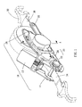
FIG. 1 is a perspective view of a tie-down device according to the first embodiment of the present invention; -
FIG. 2 is an exploded view of the tie-down device shown inFIG. 1 ; -
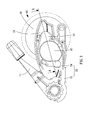
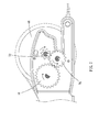
FIG. 3 is a side view of the tie-down device shown inFIG. 1 ; -
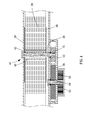
FIG. 4 is a cross-sectional view of the tie-down device taken along a line A-A inFIG. 3 ; -
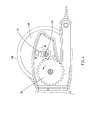
FIG. 5 is another cross-sectional view of the tie-down device shown inFIG. 1 ; -
FIG. 6 is a cross-sectional view of a tie-down device according to the second embodiment of the present invention; -
FIG. 7 is another cross-sectional view of the tie-down device shown inFIG. 6 ; -
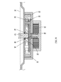
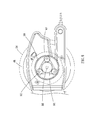
FIG. 8 is a cross-sectional view of a tie-down device according to the third embodiment of the present invention; and -
FIG. 9 is another cross-sectional view of the tie-down device shown inFIG. 8 . - Referring to
FIGS. 1 through 5 , there is shown a tie-down device 10 according to a first embodiment of the present invention. The tie-down device 10 includes aframe 20, anaxle 14, ahandle 12, areeling unit 40, a driving unit and a speed-increasinggearbox 60. Theframe 20 includes abase 22, twoseparate walls 24 and abar 26. Thewalls 24 are formed on thebase 22. One of thewalls 24 is formed with an outwardlyprotrusive portion 28. Thebar 26 is connected to both of thewalls 24 for reinforcing theframe 20. Ashort strap 30 includes an end connected to thebar 26 and another end connected to ahook 32. - The
handle 12 is connected to theaxle 14. Theaxle 14 is supported on thewalls 24 rotationally. Along strap 34 includes a first end tied to thereeling unit 40 and a second end connected to ahook 32. Thelong strap 34 is inserted via a slot defined in theaxle 14. Thelong strap 34 can be wound onto theaxle 14 by operating thehandle 12. - The
reeling unit 40 includes anaxle 42 for rotationally supporting areel 44 on thewalls 24. Thereel 44 includes atube 46 placed between and connected to twowheels 48 by welding or soldering. Thetube 46 includes aslit 47 longitudinally made therein. Each of thewheels 48 includes anaperture 49 centrally made therein. Theaxle 42 is axially inserted in thetube 46 through theapertures 49 of thewheels 48. - The first end of the
long trap 34 is tied to theaxle 42 after it is inserted in thetube 46 through theslit 47. Thelong strap 34 can be wound on thetube 46. Thewheels 48 position and prevent thelong strap 34 from rubbing against thewalls 24. - The speed-increasing
gearbox 60 includes ashell 62, alarge gear 70, asmall gear 72 and anaxle 80. Theaxle 80 is rotationally supported on thewalls 24. Theaxle 80 includes a butt (not shown) formed at an end and aslit 86 defined in an opposite end. Aclip 84 is placed in a groove defined in theaxle 80 near the butt. The butt is placed against an internal side of the outwardlyprotrusive portion 28 of thewall 24 while aclip 84 is placed against an external side of the same to keep theaxle 80 on the outwardlyprotrusive portion 28 of thewall 24. - The
large gear 70 is secured to theaxle 80 so that they are rotatable together. Thesmall gear 72 is secured to theaxle 42 so that they are rotatable together. Thesmall gear 72 is meshed with thelarge gear 70. Preferably, thelarge gear 70 includes teeth three times as many as thesmall gear 72 so that thesmall gear 72 rotates for three rounds as thelarge gear 70 rotates for one round. - The
large gear 70 and thesmall gear 72 are protectively covered by theshell 62.Screws 64 are used to connect theshell 62 to thewall 24 that is formed with the outwardlyprotrusive portion 28. - The driving unit includes a
coil spring 50 and acover 52. Thecoil spring 50 includes anexternal end 54 hooking a tab extending from an internal side of thecover 52 and aninternal end 56 extending through aslit 86 defined in theaxle 80. Thecover 52 is connected to thewall 24 that is formed with the outwardlyprotrusive portion 28. - The
coil spring 50 is loaded as thelong strap 34 is unwound from thereel 44. Thelong strap 34 can be wound onto thereel 44 by thecoil spring 50 via the speed-increasinggearbox 60. Thecoil spring 50 does not have to be long to wind along strap 34 onto thereel 44 due to the use of the speed-increasinggearbox 60. Thecoil spring 50 can be small and light. Thecoil spring 50 requires only a small amount of steel and is hence inexpensive. - Referring to
FIGS. 6 and7 , there is shown a tie-down device according to a second embodiment of the present invention. The second embodiment is like the first embodiment except several things. At first, there is used amotor 51 instead of thecoil spring 50. Themotor 51 is connected to thecover 52. Thelarge gear 70 is connected to amandrel 53 of themotor 51. Secondly, there is used amedium gear 76 between thelarge gear 70 and thesmall gear 72. Preferably, the large gear70 includes twenty-four teeth, themedium gear 76 includes sixteen teeth, and thesmall gear 72 includes eight teeth so that thesmall gear 72 rotates for three rounds as thelarge gear 70 rotates for one round. Thirdly, theaxle 80 is omitted. Fourthly, thecover 52 is omitted. - Referring to
FIGS. 8 and9 , there is shown a tie-down device according to a third embodiment of the present invention. The third embodiment is like the first embodiment except that speed-increasinggearbox 60 includes a planetary gear train instead of thelarge gear 70 and thesmall gear 72. The planetary gear train inherently includes aninternal gear 90, severalplanetary gears 92, asun gear 94 and acarrier 96. Preferably, there are threeplanetary gears 92. Theplanetary gears 92 and thesun gear 94 are rotationally supported on thecarrier 96. Each of theplanetary gears 92 is meshed with theinternal gear 90 and thesun gear 94. - The
internal gear 90 is non-rotationally placed in theshell 62. Thecarrier 96 is connected to theaxle 80 so that they are rotatable together. Thesun gear 94 is connected to theaxle 42 so that they are rotatable together. - The
coil spring 50 rotates theaxle 80 as well as thecarrier 96. Thecarrier 96 rotates thesun gear 94 as well as theaxle 42 via the planetary gears 92. Theaxles - Preferably, the
internal gear 90 includes forty-eight teeth, each of theplanetary gears 92 includes twelve gears, and thesun gear 94 includes twenty-four teeth. Thus, thesun gear 94 rotates for four rounds as thecarrier 96 rotates one round. - The present invention has been described via the detailed illustration of the embodiments. Those skilled in the art can derive variations from the embodiments without departing from the scope of the present invention. Therefore, the embodiments shall not limit the scope of the present invention defined in the claims.
Claims (15)
- A tie-down device including:a frame (20) including a base (22) and first and second walls (24) extending from the base (22);a strap (30);a reeling unit (40) including a reel (44) and an axle (42) for rotationally supporting the reel (44) on the first and second walls (24) for reeling the strap (30);a driving unit supported on the first wall (24); anda gearbox (60) for connecting the driving unit to the reeling unit (40).
- The tie-down device according to claim 1, wherein the driving unit includes a coil spring (50) connected to the first wall (24) at an end and connected to the axle (42) at another end.
- The tie-down device according to claim 2, wherein the driving unit further includes a cover (52) attached to the first wall (24) for covering the coil spring (50).
- The tie-down device according to claim 1, wherein the driving unit includes a motor (51) supported on the first wall (24) and operatively connected to the speed-increasing unit (60).
- The tie-down device according to claim 1, wherein the gearbox (60) is a speed-increasing gearbox (60).
- The tie-down device according to claim 5, wherein the gearbox (60) includes:a small gear (72) connected to the axle (42) so that they are rotatable together; anda large gear (70) engaged with the small gear (72) and connected to the driving unit.
- The tie-down device according to claim 6, wherein the gearbox (60) includes an axle (80) rotationally supported on the first wall (24) and connected to the large gear (70) so that they are rotatable together.
- The tie-down device according to claim 7, wherein the gearbox (60) further includes a clip (84) fit on the axle (80) and placed against an opposite side of the first wall (24).
- The tie-down device according to claim 6, wherein the gearbox (60) includes a shell (62) attached to the first wall (24) for shielding the small and large gears (72, 70).
- The tie-down device according to claim 6, wherein the gearbox (60) further includes a medium gear (76) provided between the small and large gears (72, 70).
- The tie-down device according to claim 5, wherein the gearbox (60) includes:an internal gear (90) non-rotationally supported on the first wall (24);a carrier (96) rotationally placed in the internal gear (90) and connected to the driving unit;planetary gears (92) rotationally supported on the carrier (96) and meshed with the internal gear (90); anda sun gear (94) connected to the axle (42) so that they are rotatable together and meshed with the planetary gears (92).
- The tie-down device according to claim 11, wherein the gearbox (60) further includes an axle (80) connected to the carrier (96) so that they are rotatable together and connected to the driving unit.
- The tie-down device according to claim 4, wherein the gearbox (60) is a speed-increasing gearbox (60).
- The tie-down device according to claim 13, wherein the gear box (60) includes:a small gear (72) connected to the axle (42) so that they are rotatable together; anda large gear (70) operatively connected to the motor (51).
- The tie-down device according to claim 13, wherein the motor (51) includes a mandrel (53) connected to the large gear (70).
Applications Claiming Priority (1)
| Application Number | Priority Date | Filing Date | Title |
|---|---|---|---|
| TW102104077A TWI527735B (en) | 2013-02-01 | 2013-02-01 | Improved hand puller |
Publications (3)
| Publication Number | Publication Date |
|---|---|
| EP2762357A2 true EP2762357A2 (en) | 2014-08-06 |
| EP2762357A3 EP2762357A3 (en) | 2015-07-08 |
| EP2762357B1 EP2762357B1 (en) | 2018-11-14 |
Family
ID=49150742
Family Applications (1)
| Application Number | Title | Priority Date | Filing Date |
|---|---|---|---|
| EP13182644.8A Active EP2762357B1 (en) | 2013-02-01 | 2013-09-02 | Tie-down device |
Country Status (4)
| Country | Link |
|---|---|
| EP (1) | EP2762357B1 (en) |
| JP (1) | JP6327661B2 (en) |
| AU (3) | AU2013224691B2 (en) |
| TW (1) | TWI527735B (en) |
Family Cites Families (13)
| Publication number | Priority date | Publication date | Assignee | Title |
|---|---|---|---|---|
| JPS6439367U (en) * | 1987-09-02 | 1989-03-09 | ||
| JP2602960B2 (en) * | 1989-09-22 | 1997-04-23 | 株式会社ヤマダコーポレーション | Reel device |
| JP2586880Y2 (en) * | 1993-07-09 | 1998-12-14 | 三菱重工業株式会社 | Belt fastening device with winding device |
| US5388609A (en) * | 1994-01-06 | 1995-02-14 | Ghio; Gary L. | Hose reel cart |
| JP3101165B2 (en) * | 1994-11-04 | 2000-10-23 | 三菱電機株式会社 | Vacuum pump with planetary gearbox |
| JP3067203U (en) * | 1999-09-03 | 2000-03-31 | 鯛勝産業株式会社 | Gear splicing recoil reel winding device |
| US6609275B1 (en) * | 2002-02-05 | 2003-08-26 | Chia-Sheng Lin | Strap tightener with an auto-pulling device |
| MXPA05008034A (en) * | 2003-01-27 | 2006-01-27 | Groupe 2T2 Inc | Winch, vehicle including the same and method of operating associated thereto. |
| DE602004028438D1 (en) * | 2003-01-27 | 2010-09-16 | Groupe 2T2 Inc | WINCH, THIS INCLUDING VEHICLE AND ASSOCIATED METHOD OF ACTIVITY |
| CA2507849C (en) * | 2003-01-27 | 2012-04-24 | Groupe 2T2 Inc. | Winch, vehicle including the same and method of operating associated thereto |
| US7350767B2 (en) * | 2005-03-03 | 2008-04-01 | Han-Ching Huang | Strapping apparatus |
| JP5102006B2 (en) * | 2007-12-14 | 2012-12-19 | 中発販売株式会社 | Reel device with tension adjustment mechanism |
| TW201132575A (en) * | 2010-03-26 | 2011-10-01 | Yeu Yueh Entpr Co Ltd | Hand puller |
-
2013
- 2013-02-01 TW TW102104077A patent/TWI527735B/en active
- 2013-09-02 EP EP13182644.8A patent/EP2762357B1/en active Active
- 2013-09-05 AU AU2013224691A patent/AU2013224691B2/en active Active
- 2013-09-10 JP JP2013187200A patent/JP6327661B2/en active Active
-
2016
- 2016-06-15 AU AU2016204040A patent/AU2016204040A1/en not_active Abandoned
- 2016-06-15 AU AU2016204001A patent/AU2016204001A1/en not_active Abandoned
Also Published As
| Publication number | Publication date |
|---|---|
| TWI527735B (en) | 2016-04-01 |
| EP2762357A3 (en) | 2015-07-08 |
| JP6327661B2 (en) | 2018-05-23 |
| AU2013224691B2 (en) | 2016-07-07 |
| EP2762357B1 (en) | 2018-11-14 |
| TW201431746A (en) | 2014-08-16 |
| AU2016204001A1 (en) | 2016-07-07 |
| JP2014149077A (en) | 2014-08-21 |
| AU2016204040A1 (en) | 2016-06-30 |
| AU2013224691A1 (en) | 2014-08-21 |
Similar Documents
| Publication | Publication Date | Title |
|---|---|---|
| US8905379B2 (en) | Tie-down device | |
| EP3601943B1 (en) | Tape measure with epicyclic gear drive for tape retraction | |
| US8684390B1 (en) | Retractable tow strap apparatus | |
| EP2605935B1 (en) | Method and device for winding up and storing a belt-like object, in particular a tightening strap | |
| DE102016207739A1 (en) | Linen storage device | |
| EP2762357B1 (en) | Tie-down device | |
| JP2018023321A (en) | Double bearing reel | |
| US2587308A (en) | Trolling reel | |
| JP6121293B2 (en) | Wreck belt recovery device | |
| WO2014014617A3 (en) | Reel system | |
| CN206915507U (en) | A kind of euphroe for circular rope | |
| US1051914A (en) | Strap-support for guns. | |
| ES1073381U (en) | Drum for the collection of replacement wheels of motor vehicles through a cable (Machine-translation by Google Translate, not legally binding) | |
| US4580741A (en) | Line guide holder for a double bearing reel | |
| CN223397236U (en) | Automatic cable storage device | |
| DE102016213670A1 (en) | Linen storage device | |
| AU2017200142B2 (en) | Winding device for coiling tensioning straps | |
| AU2017251819A1 (en) | Strap Winder | |
| AU2013221961A1 (en) | Tow strap apparatus | |
| JP2025018996A (en) | Plate body regulating mechanism for payout winding device | |
| GR2003229Y (en) | CABLES, ROPES AND FLEXIBLE PIPES ARRANGEMENT-WRAPPER | |
| EP2556994B1 (en) | Strap-Tensioning Apparatus | |
| JP3134520U (en) | Awning sheet drawer positioning device | |
| JP3033099U (en) | String winding storage equipment | |
| EP1719408A1 (en) | Fishing reel |
Legal Events
| Date | Code | Title | Description |
|---|---|---|---|
| PUAI | Public reference made under article 153(3) epc to a published international application that has entered the european phase |
Free format text: ORIGINAL CODE: 0009012 |
|
| 17P | Request for examination filed |
Effective date: 20130902 |
|
| AK | Designated contracting states |
Kind code of ref document: A2 Designated state(s): AL AT BE BG CH CY CZ DE DK EE ES FI FR GB GR HR HU IE IS IT LI LT LU LV MC MK MT NL NO PL PT RO RS SE SI SK SM TR |
|
| AX | Request for extension of the european patent |
Extension state: BA ME |
|
| R17P | Request for examination filed (corrected) |
Effective date: 20141215 |
|
| PUAL | Search report despatched |
Free format text: ORIGINAL CODE: 0009013 |
|
| AK | Designated contracting states |
Kind code of ref document: A3 Designated state(s): AL AT BE BG CH CY CZ DE DK EE ES FI FR GB GR HR HU IE IS IT LI LT LU LV MC MK MT NL NO PL PT RO RS SE SI SK SM TR |
|
| AX | Request for extension of the european patent |
Extension state: BA ME |
|
| RIC1 | Information provided on ipc code assigned before grant |
Ipc: B60P 7/08 20060101AFI20150601BHEP Ipc: B65H 54/58 20060101ALI20150601BHEP |
|
| RBV | Designated contracting states (corrected) |
Designated state(s): AL AT BE BG CH CY CZ DE DK EE ES FI FR GB GR HR HU IE IS IT LI LT LU LV MC MK MT NL NO PL PT RO RS SE SI SK SM TR |
|
| GRAP | Despatch of communication of intention to grant a patent |
Free format text: ORIGINAL CODE: EPIDOSNIGR1 |
|
| STAA | Information on the status of an ep patent application or granted ep patent |
Free format text: STATUS: GRANT OF PATENT IS INTENDED |
|
| INTG | Intention to grant announced |
Effective date: 20180524 |
|
| GRAS | Grant fee paid |
Free format text: ORIGINAL CODE: EPIDOSNIGR3 |
|
| GRAA | (expected) grant |
Free format text: ORIGINAL CODE: 0009210 |
|
| STAA | Information on the status of an ep patent application or granted ep patent |
Free format text: STATUS: THE PATENT HAS BEEN GRANTED |
|
| AK | Designated contracting states |
Kind code of ref document: B1 Designated state(s): AL AT BE BG CH CY CZ DE DK EE ES FI FR GB GR HR HU IE IS IT LI LT LU LV MC MK MT NL NO PL PT RO RS SE SI SK SM TR |
|
| REG | Reference to a national code |
Ref country code: CH Ref legal event code: EP Ref country code: AT Ref legal event code: REF Ref document number: 1064409 Country of ref document: AT Kind code of ref document: T Effective date: 20181115 |
|
| REG | Reference to a national code |
Ref country code: DE Ref legal event code: R096 Ref document number: 602013046579 Country of ref document: DE |
|
| REG | Reference to a national code |
Ref country code: IE Ref legal event code: FG4D |
|
| REG | Reference to a national code |
Ref country code: NL Ref legal event code: MP Effective date: 20181114 |
|
| REG | Reference to a national code |
Ref country code: LT Ref legal event code: MG4D |
|
| REG | Reference to a national code |
Ref country code: AT Ref legal event code: MK05 Ref document number: 1064409 Country of ref document: AT Kind code of ref document: T Effective date: 20181114 |
|
| PG25 | Lapsed in a contracting state [announced via postgrant information from national office to epo] |
Ref country code: NO Free format text: LAPSE BECAUSE OF FAILURE TO SUBMIT A TRANSLATION OF THE DESCRIPTION OR TO PAY THE FEE WITHIN THE PRESCRIBED TIME-LIMIT Effective date: 20190214 Ref country code: BG Free format text: LAPSE BECAUSE OF FAILURE TO SUBMIT A TRANSLATION OF THE DESCRIPTION OR TO PAY THE FEE WITHIN THE PRESCRIBED TIME-LIMIT Effective date: 20190214 Ref country code: IS Free format text: LAPSE BECAUSE OF FAILURE TO SUBMIT A TRANSLATION OF THE DESCRIPTION OR TO PAY THE FEE WITHIN THE PRESCRIBED TIME-LIMIT Effective date: 20190314 Ref country code: FI Free format text: LAPSE BECAUSE OF FAILURE TO SUBMIT A TRANSLATION OF THE DESCRIPTION OR TO PAY THE FEE WITHIN THE PRESCRIBED TIME-LIMIT Effective date: 20181114 Ref country code: LT Free format text: LAPSE BECAUSE OF FAILURE TO SUBMIT A TRANSLATION OF THE DESCRIPTION OR TO PAY THE FEE WITHIN THE PRESCRIBED TIME-LIMIT Effective date: 20181114 Ref country code: AT Free format text: LAPSE BECAUSE OF FAILURE TO SUBMIT A TRANSLATION OF THE DESCRIPTION OR TO PAY THE FEE WITHIN THE PRESCRIBED TIME-LIMIT Effective date: 20181114 Ref country code: ES Free format text: LAPSE BECAUSE OF FAILURE TO SUBMIT A TRANSLATION OF THE DESCRIPTION OR TO PAY THE FEE WITHIN THE PRESCRIBED TIME-LIMIT Effective date: 20181114 Ref country code: LV Free format text: LAPSE BECAUSE OF FAILURE TO SUBMIT A TRANSLATION OF THE DESCRIPTION OR TO PAY THE FEE WITHIN THE PRESCRIBED TIME-LIMIT Effective date: 20181114 Ref country code: HR Free format text: LAPSE BECAUSE OF FAILURE TO SUBMIT A TRANSLATION OF THE DESCRIPTION OR TO PAY THE FEE WITHIN THE PRESCRIBED TIME-LIMIT Effective date: 20181114 |
|
| PG25 | Lapsed in a contracting state [announced via postgrant information from national office to epo] |
Ref country code: AL Free format text: LAPSE BECAUSE OF FAILURE TO SUBMIT A TRANSLATION OF THE DESCRIPTION OR TO PAY THE FEE WITHIN THE PRESCRIBED TIME-LIMIT Effective date: 20181114 Ref country code: NL Free format text: LAPSE BECAUSE OF FAILURE TO SUBMIT A TRANSLATION OF THE DESCRIPTION OR TO PAY THE FEE WITHIN THE PRESCRIBED TIME-LIMIT Effective date: 20181114 Ref country code: SE Free format text: LAPSE BECAUSE OF FAILURE TO SUBMIT A TRANSLATION OF THE DESCRIPTION OR TO PAY THE FEE WITHIN THE PRESCRIBED TIME-LIMIT Effective date: 20181114 Ref country code: RS Free format text: LAPSE BECAUSE OF FAILURE TO SUBMIT A TRANSLATION OF THE DESCRIPTION OR TO PAY THE FEE WITHIN THE PRESCRIBED TIME-LIMIT Effective date: 20181114 Ref country code: PT Free format text: LAPSE BECAUSE OF FAILURE TO SUBMIT A TRANSLATION OF THE DESCRIPTION OR TO PAY THE FEE WITHIN THE PRESCRIBED TIME-LIMIT Effective date: 20190314 Ref country code: GR Free format text: LAPSE BECAUSE OF FAILURE TO SUBMIT A TRANSLATION OF THE DESCRIPTION OR TO PAY THE FEE WITHIN THE PRESCRIBED TIME-LIMIT Effective date: 20190215 |
|
| PG25 | Lapsed in a contracting state [announced via postgrant information from national office to epo] |
Ref country code: PL Free format text: LAPSE BECAUSE OF FAILURE TO SUBMIT A TRANSLATION OF THE DESCRIPTION OR TO PAY THE FEE WITHIN THE PRESCRIBED TIME-LIMIT Effective date: 20181114 Ref country code: DK Free format text: LAPSE BECAUSE OF FAILURE TO SUBMIT A TRANSLATION OF THE DESCRIPTION OR TO PAY THE FEE WITHIN THE PRESCRIBED TIME-LIMIT Effective date: 20181114 Ref country code: CZ Free format text: LAPSE BECAUSE OF FAILURE TO SUBMIT A TRANSLATION OF THE DESCRIPTION OR TO PAY THE FEE WITHIN THE PRESCRIBED TIME-LIMIT Effective date: 20181114 Ref country code: IT Free format text: LAPSE BECAUSE OF FAILURE TO SUBMIT A TRANSLATION OF THE DESCRIPTION OR TO PAY THE FEE WITHIN THE PRESCRIBED TIME-LIMIT Effective date: 20181114 |
|
| REG | Reference to a national code |
Ref country code: DE Ref legal event code: R097 Ref document number: 602013046579 Country of ref document: DE |
|
| PG25 | Lapsed in a contracting state [announced via postgrant information from national office to epo] |
Ref country code: EE Free format text: LAPSE BECAUSE OF FAILURE TO SUBMIT A TRANSLATION OF THE DESCRIPTION OR TO PAY THE FEE WITHIN THE PRESCRIBED TIME-LIMIT Effective date: 20181114 Ref country code: SM Free format text: LAPSE BECAUSE OF FAILURE TO SUBMIT A TRANSLATION OF THE DESCRIPTION OR TO PAY THE FEE WITHIN THE PRESCRIBED TIME-LIMIT Effective date: 20181114 Ref country code: SK Free format text: LAPSE BECAUSE OF FAILURE TO SUBMIT A TRANSLATION OF THE DESCRIPTION OR TO PAY THE FEE WITHIN THE PRESCRIBED TIME-LIMIT Effective date: 20181114 Ref country code: RO Free format text: LAPSE BECAUSE OF FAILURE TO SUBMIT A TRANSLATION OF THE DESCRIPTION OR TO PAY THE FEE WITHIN THE PRESCRIBED TIME-LIMIT Effective date: 20181114 |
|
| PLBE | No opposition filed within time limit |
Free format text: ORIGINAL CODE: 0009261 |
|
| STAA | Information on the status of an ep patent application or granted ep patent |
Free format text: STATUS: NO OPPOSITION FILED WITHIN TIME LIMIT |
|
| 26N | No opposition filed |
Effective date: 20190815 |
|
| PG25 | Lapsed in a contracting state [announced via postgrant information from national office to epo] |
Ref country code: SI Free format text: LAPSE BECAUSE OF FAILURE TO SUBMIT A TRANSLATION OF THE DESCRIPTION OR TO PAY THE FEE WITHIN THE PRESCRIBED TIME-LIMIT Effective date: 20181114 |
|
| PG25 | Lapsed in a contracting state [announced via postgrant information from national office to epo] |
Ref country code: TR Free format text: LAPSE BECAUSE OF FAILURE TO SUBMIT A TRANSLATION OF THE DESCRIPTION OR TO PAY THE FEE WITHIN THE PRESCRIBED TIME-LIMIT Effective date: 20181114 |
|
| PG25 | Lapsed in a contracting state [announced via postgrant information from national office to epo] |
Ref country code: MC Free format text: LAPSE BECAUSE OF FAILURE TO SUBMIT A TRANSLATION OF THE DESCRIPTION OR TO PAY THE FEE WITHIN THE PRESCRIBED TIME-LIMIT Effective date: 20181114 |
|
| REG | Reference to a national code |
Ref country code: CH Ref legal event code: PL |
|
| PG25 | Lapsed in a contracting state [announced via postgrant information from national office to epo] |
Ref country code: LU Free format text: LAPSE BECAUSE OF NON-PAYMENT OF DUE FEES Effective date: 20190902 Ref country code: IE Free format text: LAPSE BECAUSE OF NON-PAYMENT OF DUE FEES Effective date: 20190902 Ref country code: LI Free format text: LAPSE BECAUSE OF NON-PAYMENT OF DUE FEES Effective date: 20190930 Ref country code: CH Free format text: LAPSE BECAUSE OF NON-PAYMENT OF DUE FEES Effective date: 20190930 |
|
| REG | Reference to a national code |
Ref country code: BE Ref legal event code: MM Effective date: 20190930 |
|
| PG25 | Lapsed in a contracting state [announced via postgrant information from national office to epo] |
Ref country code: BE Free format text: LAPSE BECAUSE OF NON-PAYMENT OF DUE FEES Effective date: 20190930 |
|
| PG25 | Lapsed in a contracting state [announced via postgrant information from national office to epo] |
Ref country code: FR Free format text: LAPSE BECAUSE OF NON-PAYMENT OF DUE FEES Effective date: 20190930 |
|
| PG25 | Lapsed in a contracting state [announced via postgrant information from national office to epo] |
Ref country code: CY Free format text: LAPSE BECAUSE OF FAILURE TO SUBMIT A TRANSLATION OF THE DESCRIPTION OR TO PAY THE FEE WITHIN THE PRESCRIBED TIME-LIMIT Effective date: 20181114 |
|
| PG25 | Lapsed in a contracting state [announced via postgrant information from national office to epo] |
Ref country code: MT Free format text: LAPSE BECAUSE OF FAILURE TO SUBMIT A TRANSLATION OF THE DESCRIPTION OR TO PAY THE FEE WITHIN THE PRESCRIBED TIME-LIMIT Effective date: 20181114 Ref country code: HU Free format text: LAPSE BECAUSE OF FAILURE TO SUBMIT A TRANSLATION OF THE DESCRIPTION OR TO PAY THE FEE WITHIN THE PRESCRIBED TIME-LIMIT; INVALID AB INITIO Effective date: 20130902 |
|
| PG25 | Lapsed in a contracting state [announced via postgrant information from national office to epo] |
Ref country code: MK Free format text: LAPSE BECAUSE OF FAILURE TO SUBMIT A TRANSLATION OF THE DESCRIPTION OR TO PAY THE FEE WITHIN THE PRESCRIBED TIME-LIMIT Effective date: 20181114 |
|
| PGFP | Annual fee paid to national office [announced via postgrant information from national office to epo] |
Ref country code: DE Payment date: 20250924 Year of fee payment: 13 |
|
| PGFP | Annual fee paid to national office [announced via postgrant information from national office to epo] |
Ref country code: GB Payment date: 20250930 Year of fee payment: 13 |