EP2762189A1 - Slitted pipe and guide wire using the same - Google Patents
Slitted pipe and guide wire using the same Download PDFInfo
- Publication number
- EP2762189A1 EP2762189A1 EP14152817.4A EP14152817A EP2762189A1 EP 2762189 A1 EP2762189 A1 EP 2762189A1 EP 14152817 A EP14152817 A EP 14152817A EP 2762189 A1 EP2762189 A1 EP 2762189A1
- Authority
- EP
- European Patent Office
- Prior art keywords
- slitted pipe
- slit
- slit pattern
- guide wire
- slitted
- Prior art date
- Legal status (The legal status is an assumption and is not a legal conclusion. Google has not performed a legal analysis and makes no representation as to the accuracy of the status listed.)
- Withdrawn
Links
- 230000007423 decrease Effects 0.000 claims description 8
- 210000004204 blood vessel Anatomy 0.000 description 26
- 238000005219 brazing Methods 0.000 description 7
- 230000001684 chronic effect Effects 0.000 description 5
- 230000003902 lesion Effects 0.000 description 5
- 229920000642 polymer Polymers 0.000 description 4
- 230000002792 vascular Effects 0.000 description 3
- 229910045601 alloy Inorganic materials 0.000 description 2
- 239000000956 alloy Substances 0.000 description 2
- 239000011248 coating agent Substances 0.000 description 2
- 229920001577 copolymer Polymers 0.000 description 2
- 238000007689 inspection Methods 0.000 description 2
- WCDDVEOXEIYWFB-VXORFPGASA-N (2s,3s,4r,5r,6r)-3-[(2s,3r,5s,6r)-3-acetamido-5-hydroxy-6-(hydroxymethyl)oxan-2-yl]oxy-4,5,6-trihydroxyoxane-2-carboxylic acid Chemical compound CC(=O)N[C@@H]1C[C@H](O)[C@@H](CO)O[C@H]1O[C@@H]1[C@@H](C(O)=O)O[C@@H](O)[C@H](O)[C@H]1O WCDDVEOXEIYWFB-VXORFPGASA-N 0.000 description 1
- HRPVXLWXLXDGHG-UHFFFAOYSA-N Acrylamide Chemical compound NC(=O)C=C HRPVXLWXLXDGHG-UHFFFAOYSA-N 0.000 description 1
- 239000004677 Nylon Substances 0.000 description 1
- 229920003171 Poly (ethylene oxide) Polymers 0.000 description 1
- 239000004372 Polyvinyl alcohol Substances 0.000 description 1
- 230000001154 acute effect Effects 0.000 description 1
- 230000005540 biological transmission Effects 0.000 description 1
- 229920001400 block copolymer Polymers 0.000 description 1
- 230000008602 contraction Effects 0.000 description 1
- 238000005530 etching Methods 0.000 description 1
- 210000001035 gastrointestinal tract Anatomy 0.000 description 1
- 229940014041 hyaluronate Drugs 0.000 description 1
- KHYBPSFKEHXSLX-UHFFFAOYSA-N iminotitanium Chemical compound [Ti]=N KHYBPSFKEHXSLX-UHFFFAOYSA-N 0.000 description 1
- 238000003754 machining Methods 0.000 description 1
- FPYJFEHAWHCUMM-UHFFFAOYSA-N maleic anhydride Chemical compound O=C1OC(=O)C=C1 FPYJFEHAWHCUMM-UHFFFAOYSA-N 0.000 description 1
- 239000000463 material Substances 0.000 description 1
- 238000000034 method Methods 0.000 description 1
- 229910001000 nickel titanium Inorganic materials 0.000 description 1
- 229920001778 nylon Polymers 0.000 description 1
- 210000000056 organ Anatomy 0.000 description 1
- -1 poly(glycidyl methacrylate-dimethylacrylamide) Polymers 0.000 description 1
- 229920002401 polyacrylamide Polymers 0.000 description 1
- 229920002451 polyvinyl alcohol Polymers 0.000 description 1
- 229920000036 polyvinylpyrrolidone Polymers 0.000 description 1
- 239000001267 polyvinylpyrrolidone Substances 0.000 description 1
- 235000013855 polyvinylpyrrolidone Nutrition 0.000 description 1
- 239000010935 stainless steel Substances 0.000 description 1
- 229910001220 stainless steel Inorganic materials 0.000 description 1
- 210000000626 ureter Anatomy 0.000 description 1
Images



Classifications
-
- A—HUMAN NECESSITIES
- A61—MEDICAL OR VETERINARY SCIENCE; HYGIENE
- A61M—DEVICES FOR INTRODUCING MEDIA INTO, OR ONTO, THE BODY; DEVICES FOR TRANSDUCING BODY MEDIA OR FOR TAKING MEDIA FROM THE BODY; DEVICES FOR PRODUCING OR ENDING SLEEP OR STUPOR
- A61M25/00—Catheters; Hollow probes
- A61M25/01—Introducing, guiding, advancing, emplacing or holding catheters
- A61M25/09—Guide wires
-
- A—HUMAN NECESSITIES
- A61—MEDICAL OR VETERINARY SCIENCE; HYGIENE
- A61M—DEVICES FOR INTRODUCING MEDIA INTO, OR ONTO, THE BODY; DEVICES FOR TRANSDUCING BODY MEDIA OR FOR TAKING MEDIA FROM THE BODY; DEVICES FOR PRODUCING OR ENDING SLEEP OR STUPOR
- A61M25/00—Catheters; Hollow probes
- A61M25/0043—Catheters; Hollow probes characterised by structural features
- A61M25/0054—Catheters; Hollow probes characterised by structural features with regions for increasing flexibility
-
- A—HUMAN NECESSITIES
- A61—MEDICAL OR VETERINARY SCIENCE; HYGIENE
- A61M—DEVICES FOR INTRODUCING MEDIA INTO, OR ONTO, THE BODY; DEVICES FOR TRANSDUCING BODY MEDIA OR FOR TAKING MEDIA FROM THE BODY; DEVICES FOR PRODUCING OR ENDING SLEEP OR STUPOR
- A61M25/00—Catheters; Hollow probes
- A61M25/01—Introducing, guiding, advancing, emplacing or holding catheters
- A61M25/09—Guide wires
- A61M2025/09133—Guide wires having specific material compositions or coatings; Materials with specific mechanical behaviours, e.g. stiffness, strength to transmit torque
-
- A—HUMAN NECESSITIES
- A61—MEDICAL OR VETERINARY SCIENCE; HYGIENE
- A61M—DEVICES FOR INTRODUCING MEDIA INTO, OR ONTO, THE BODY; DEVICES FOR TRANSDUCING BODY MEDIA OR FOR TAKING MEDIA FROM THE BODY; DEVICES FOR PRODUCING OR ENDING SLEEP OR STUPOR
- A61M25/00—Catheters; Hollow probes
- A61M25/0009—Making of catheters or other medical or surgical tubes
- A61M25/0013—Weakening parts of a catheter tubing, e.g. by making cuts in the tube or reducing thickness of a layer at one point to adjust the flexibility
Definitions
- the present invention relates to a slitted pipe for use in a medical instrument to be inserted in a body cavity for medical treatment and inspection, and a guide wire using the slitted pipe.
- Patent Document 1 Japanese Unexamined Patent Application Publication (Translation of PCT Application) No. 2009-519103 (Patent Document 1) describes a medical instrument including a hypotube in which a plurality of cuts, such as grooves, are helically formed in a tubular member. Some of the grooves provided in the tubular member are each composed of a first part extending at an acute angle to an axis of the tubular member and a second part connected substantially orthogonally to the first part.
- a distal end of the guide wire does sometimes not sufficiently advance into the chronic total occlusion lesion. It is considered that this is because transmissibility of push-in torque for properly advancing the distal end of the guide wire deep is not sufficiently exerted when the guide wire is pushed in in an axial direction.
- the present invention has been made in view of these circumstances, and an object of the invention is to provide a slitted pipe that can easily ensure sufficient transmissibility of push-in torque in both clockwise and counterclockwise rotations, and a guide wire using the slitted pipe.
- a slitted pipe and a guide wire using the slitted pipe according to aspects of the present invention have the following characteristics.
- a slitted pipe includes at least one first slit pattern helically extending in a longitudinal direction of the slitted pipe and divided by girders at predetermined intervals, and at least one second slit pattern helically extending in the longitudinal direction and disposed at an angle to the first slit pattern to cross the girders.
- a slit pattern means a helical pattern comprising a plurality of slits ( Fig.1 to 3 ) divided by the girders and arranged on the same helical shape in a row.
- a slit pattern may also comprise a plurality of slit groups ( Fig.4 ) divided by the girders and arranged on the same helical shape in a row.
- a slit group comprises a plurality of slits disposed adjacent and parallel to one another ( Fig.4 ).
- the slitted pipe of the present invention comprises at least one first slit pattern and at least one second slit pattern
- the slitted pipe of the present invention may also comprise a plurality of parallel first slit patterns and a plurality of parallel second slit patterns ( Fig. 1 to 4 ).
- both a Z-helical (right-handed helical) slit pattern and an S-helical (left-handed helical) slit pattern are provided apart from each other.
- the slitted pipe when the slitted pipe is pushed into a blood vessel while being rotated in the clockwise direction, it is compressed to decrease the distances between adjacent slits of the right-handed helical slit pattern, and stress produced at this time acts in a push-in direction. Hence, transmissibility of push-in torque is enhanced, and this allows a distal end portion of the slitted pipe to properly advance deep into the blood vessel.
- the slitted pipe when the slitted pipe is pushed into the blood vessel while being rotated in the counterclockwise direction, it is similarly compressed to decrease the distances between adjacent slits of the left-handed helical slit pattern, and stress produced at this time acts in the push-in direction. Hence, transmissibility of push-in torque is enhanced, and this allows the distal end portion of the slitted pipe to properly advance deep into the blood vessel.
- the slitted pipe when the slitted pipe is pushed into the blood vessel while being rotated in both the clockwise and counterclockwise directions, transmissibility of the push-in torque that is equivalently high in both the clockwise and counterclockwise directions is obtained. Therefore, for example, the slitted pipe easily advances deep into a chronic total occlusion lesion, and operability is enhanced.
- a guide wire according to a second aspect of the present invention includes a core shaft, and the above slitted pipe covering a distal end portion of the core shaft.
- the guide wire of the second aspect it is possible to obtain a guide wire that easily ensures sufficient transmissibility of push-in torque and that can properly advance deep into a blood vessel.
- a guide wire includes a core shaft, a coil body covering a distal end portion of the core shaft, and the above slitted pipe disposed in the coil body to cover the distal end portion of the core shaft.
- the guide wire of the third aspect it is possible to obtain a guide wire that easily ensures sufficient transmissibility of push-in torque and that can properly advance deep into a blood vessel. Also, it is possible to ensure high flexibility of the guide wire by the slitted pipe disposed in the coil body while the outer diameter of the coil body is maintained.
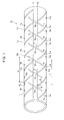
- Fig. 1 is a perspective view of a slitted pipe according to a first embodiment of the present invention.
- the slitted pipe is schematically illustrated as a whole while being shortened in a longitudinal direction. Hence, overall dimensions of the slitted pipe are different from actual ones.
- a slitted pipe 10 of the first embodiment includes two parallel first slit patterns 15a, 15b that helically extend in a longitudinal direction of a tubular member 11.
- the first slit patterns 15a and 15b are adjacent to each other in the longitudinal direction of the tubular member 11, have the same structure, and run parallel to each other.
- the first slit patterns 15a and 15b are shifted from each other by 180° in the circumferential direction of the slitted pipe 10.
- the first slit patterns 15a, 15b each are divided into a plurality of slits by girders 13 at predetermined intervals.
- the first slit patterns 15a, 15b form a right-handed helical shape in the longitudinal direction of the tubular member 11.
- the slitted pipe 10 further includes two parallel second slit patterns 16a, 16b.
- the second slit patterns 16a and 16b are adjacent to each other in the longitudinal direction of the tubular member 11, have the same structure, and run parallel to each other.
- the second slit patterns 16a and 16b are shifted from each other by 180° in the circumferential direction of the slitted pipe 10.
- the second slit patterns 16a, 16b extend in the longitudinal direction of the tubular member 11 to be helical in a direction opposite from the first slit patterns 15a, 15b (to form a left-handed helical shape in the longitudinal direction of the tubular member 11), and cross the above-described girders 13.
- the slits of the second slit patterns 16a, 16b are not in contact with the slits of the first slit patterns 15a, 15b, and the second slit patterns 16a, 16b are disposed at an angle to the first slit patterns 15a, 15b.
- the first slit patterns 15a, 15b extending in the right-handed helical shape in the longitudinal direction of the tubular member 11 and the second slit patterns 16a, 16b extending in the left-handed helical shape in the longitudinal direction of the tubular member 11 are provided apart from each other.
- the guide wire when the guide wire is pushed into the blood vessel while the proximal end portion thereof is being rotated counterclockwise, it is similarly compressed to reduce distances between adjacent slits of the left-handed helical second slit patterns 16a, 16b, and stress produced at this time acts in the push-in direction. Hence, transmissibility of push-in torque is enhanced, and the distal end portion of the guide wire can properly advance deep into the blood vessel.
- the guide wire can easily advance into, for example, a chronic total occlusion lesion, and operability is enhanced.
- the first slit patterns 15a, 15b and the second slit patterns 16a, 16b are arranged line-symmetrically to each other with respect to an axis. Hence, both the first slit patterns 15a, 15b and the second slit patterns 16a, 16b are disposed symmetrically and uniformly.
- torque transmissibility can be substantially equivalent when the guide wire is rotated clockwise and when the guide wire is rotated counterclockwise, and torque transmissibility well balanced in a circumferential cross section can be ensured easily. Therefore, it is possible to enhance operability of the guide wire when the guide wire is inserted deep into the blood vessel.
- the slits of the first slit pattern 15a, 15b and the slits of the second slit patterns 16a, 16b are substantially equal in width.
- a pitch P1 of the first slit pattern 15a is substantially fixed.
- a pitch Q1 of the second slit pattern 16a is substantially fixed.
- the pitch P1 of the first slit pattern 15a and the pitch Q1 of the second slit pattern 16a are substantially equal to each other.
- While a method for forming the first slit patterns 15a, 15b and the second slit patterns 16a, 16b is not particularly limited, for example, laser machining or etching is used.
- the slitted pipe 10 Since the slitted pipe 10 has the first and second slit patterns in its surface, flexibility thereof can be enhanced. Hence, when the slitted pipe 10 is inserted in a blood vessel of a patient, perforation of the blood vessel can be prevented effectively.
- the slitted pipe 10 Since the slitted pipe 10 has a plurality of helical slit patterns in its surface, play is formed when rotational force applied to one end of the slitted pipe 10 is transmitted to the other end. Hence, even if great force is suddenly applied to one end of the slitted pipe 10, it can be prevented from being immediately transmitted to the other end. Thus, an accident can be avoided.
- the girders 13 that divide the first slit patterns 15a, 15b are linearly linked along the axis of the slitted pipe 10 from one end toward the other end. That is, the girders 13 are located in an area surrounded by a pair of parallel virtual lines K1 and K2. Similarly, girders 14 that divide the second slit patterns 16a, 16b into plurality of slits 16a', 16b' are linearly linked along the axis from one end toward the other end.
- the cross section of the tubular member 11 that forms the slitted pipe 10 of the first embodiment is shaped like a substantially perfect circle, an ellipse, or a polygon such as a triangle, a rectangle, a hexagon, or an octagon.
- the cross-section of the tubular member 11 is preferably shaped like a substantially perfect circle from a viewpoint of uniform transmission of rotational torque over the entire circumference.
- first slit patterns 15a, 15b and the second slit patterns 16a, 16b are arranged line-symmetrically with respect to the axis in the first embodiment
- arrangement of the first slit patterns 15a, 15b and the second slit pattern 16a, 16b is not limited thereto. That is, the first slit patterns 15a, 15b and the second slit patterns 16a, 16b do not always need to be arranged line-symmetrically with respect to the axis as long as well-balanced torque transmissibility can be easily ensured in the circumferential cross section.
- the girders 13 for dividing the first slit patterns 15a, 15b as well as the girders 14 for dividing the second slit patterns 16a, 16b are linearly linked along the axis from one end toward the other end of the slitted pipe 10 in the first embodiment
- arrangement of the girders 13 and the girders 14 is not limited thereto. That is, the girders 13 as well as the girders 14 do not always need to be linearly linked as long as high transmissibility of push-in torque of the slitted pipe 10 can be ensured.
- the girders 13 and the girders 14 may be arranged in a staggered manner.
- Fig. 2 is a perspective view of a slitted pipe according to a second embodiment of the present invention.
- a slitted pipe 20 according to the second embodiment includes a tubular member 21.
- the slit width of first slit patterns 25a, 25b increases from one end (a right side in Fig. 2 ) toward the other end (a left side in Fig. 2 ).
- the slit width of second slit patterns 26a, 26b also increases from one end (right side) toward the other end (left side).
- a slit width X1 of the first slit pattern 25a disposed at the other end (left side in Fig. 2 ) is larger than a slit width Y1 of the first slit pattern 25a disposed at one end (right side in Fig. 2 ).
- a slit width X2 of the second slit pattern 26a disposed at the other end (left side) of the slitted pipe 20 is larger than a slit width Y2 of the second slit pattern 26a disposed at one end (right side).
- advantages similar to those of the above-described first embodiment can be obtained. Further, high flexibility can be ensured at the other end (left side) of the slitted pipe 20. For example, in a guide wire including the slitted pipe 20, operability is enhanced, and insertability in a blood vessel that intricately branches in a three-dimensional space (vascular selectivity) can be enhanced. In addition, when such a guide wire is inserted in a blood vessel of a patient, perforation of the blood vessel can be prevented effectively.
- a pitch P2 of the first slit pattern 25a is fixed.
- a pitch Q2 of the second slit pattern 26a is fixed.
- the pitch P2 of the first slit pattern 25a and the pitch Q2 of the second slit pattern 26a are equal to each other.
- the slit width of the first slit patterns 25a, 25b and the slit width of the second slit patterns 26a, 26b each increase in two steps from one end (right side in Fig. 2 ) toward the other end (left side in Fig. 2 ) of the slitted pipe 20.
- the slit width of the first slit patterns 25a, 25b and the slit width of the second slit patterns 26a, 26b may each increase in three or more steps. In this case, advantages similar to those of the second embodiment can also be obtained.
- Fig. 3 is a perspective view of a slitted pipe according to a third embodiment of the present invention.
- a slitted pipe 30 of the third embodiment includes a tubular member 31.
- the pitch of first slit patterns 35a, 35b decreases from one end (a right side in Fig. 3 ) toward the other end (a left side in Fig. 3 ).
- the pitch of second slit patterns 36a, 36b decreases from one end (right side) toward the other end (left side).
- a pitch A1 of the first slit pattern 35a disposed at the other end (left side) of the slitted pipe 30 is less than a pitch B1 of the first slit pattern 35a disposed at one end (right side).
- a pitch A2 of the second slit pattern 36a disposed at the other end (left side) of the slitted pipe 30 is less than a pitch B2 of the second slit pattern 36a disposed at one end (right side) .
- advantages similar to those of the above-described first embodiment can be obtained. Further, high flexibility can be ensured at the other end (left side) of the slitted pipe 30. For example, in a guide wire including the slitted pipe 30, operability is enhanced, and insertability in a blood vessel that intricately branches in a three-dimensional space (vascular selectivity) can be enhanced. In addition, when such a guide wire is inserted in a blood vessel of a patient, perforation of the blood vessel can be prevented effectively.
- the slit width of the first slit patterns 35a, 36b and the slit width of the second slit patterns 36a, 36b are substantially equal to each other. This can enhance torque transmissibility of the slitted pipe 30 itself in a well-balanced manner in a circumferential cross section.
- the pitch of the first slit patterns 35a, 35b and the pitch of the second slit pattern 36a, 36b each decrease in two steps from one end (right side in Fig. 3 ) toward the other end (left side in Fig. 3 ).
- the pitch of the first slit patterns 35a, 35b and the pitch of the second slit patterns 36a, 36b may each increase in three or more steps. In this case, advantages similar to those of the third embodiment can also be obtained.
- Fig. 4 is a perspective view of a slitted pipe according to a fourth embodiment of the present invention.
- a slitted pipe 40 of the fourth embodiment includes a tubular member 41.
- girders 43 are provided to divide first slit patterns 45a, 45b into a plurality of slit groups45a', 45b' each composed of three slits 45a" 45b" disposed adjacent and parallel to one another.
- second slit patterns 46a, 46b each comprise a plurality of slit groups 46a', 46b' each composed of three slits 46a", 46b" disposed adjacent and parallel to one another is provided to cross the girders 43.
- the slits 46a", 46b" of the second slit patterns 46a, 46b are not in contact with the slits 45a", 45b" of the first slit patterns 45a, 45b, and the second slit patterns 46a, 46b are disposed at an angle to the first slit patterns 45a, 46b.
- a pitch C1 of the first slit pattern 45a may decrease from one end (a right side in Fig. 4 ) toward the other end (a left side in Fig. 4 ), or may be substantially fixed.
- the pitch C1 of the first slit pattern 45a preferably decreases from one end (right side) toward the other end (left side) in order to ensure high flexibility at the other end of the slitted pipe 40. This also applies to the second slit patterns 46a, 46b.
- the slit width of the first slit patterns 45a, 45b may increase from one end (right side in Fig. 4 ) toward the other end (left side in Fig. 4 ), or may be substantially fixed.
- the slit width of the first slit patterns 45a, 45b preferably increases from one end (right side) toward the other end (left side) in order to ensure high flexibility at the other end of the slitted pipe 40. This also applies to the second slit patterns 46a, 46b.
- the slit number of the slit groups in the first slit patterns 45a, 45b and the slit number of the slit groups of the second slit patterns 46a, 46b are not limited to three, and may be two, or four or more.
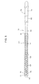
- Fig. 5 is an overall view of a first embodiment of a guide wire according to the present invention.
- a left side is a distal side to be inserted into the body, and a right side is a proximal side to be operated by a manipulator such as a doctor.
- the guide wire is schematically illustrated, and the dimensional ratio is different from an actual one.
- a guide wire 101 illustrated in Fig. 5 is used, for example, for medical treatment of a blood vessel of the heart.
- the guide wire 101 is about 1900 mm in length.
- the guide wire 101 includes a core shaft 102, a slitted pipe 103 according to any of the above-described first to fourth embodiments, a distal-end brazing part 113 that joins a distal end of the core shaft 102 and a distal end of the slitted pipe 103, and a proximal-end brazing part 115 that joins the core shaft 102 and a proximal end of the slitted pipe 103.
- the core shaft 102 includes a first distal end portion 112 provided at the most distal end, a second distal end portion 111 adjacent to a proximal end of the first distal end portion 112, a third distal end portion 110 adjacent to a proximal end of the second distal end portion 111, a first tapered portion 109 adjacent to a proximal end of the third distal end portion 110, a second tapered portion 108 adjacent to a proximal end of the first tapered portion 109, a third tapered portion 107 adjacent to a proximal end of the second tapered portion 108, a first cylindrical portion 106 adjacent to a proximal end of the third tapered portion 107, a fourth tapered portion 105 adjacent to a proximal end of the first cylindrical portion 106, and a cylindrical proximal end portion 104 adjacent to a proximal end of the fourth tapered portion 105.
- the material of the core shaft 102 is not particularly limited, for example, stainless steel (SUS304), a superelastic alloy such as a Ni-Ti alloy, or a piano wire can be used.
- hydrophilic coating agents are a cellulosic high polymer, a polyethylene oxide high polymer, a maleic anhydride high polymer (for example, a maleic anhydride copolymer such as a methyl vinyl ether-maleic anhydride copolymer), an acrylamide high polymer (for example, a block copolymer of polyacrylamide and poly(glycidyl methacrylate-dimethylacrylamide), hydrosoluble nylon, polyvinyl alcohol, polyvinylpyrrolidone, and hyaluronate.
- hydrophilic coating agents are a cellulosic high polymer, a polyethylene oxide high polymer, a maleic anhydride high polymer (for example, a maleic anhydride copolymer such as a methyl vinyl ether-maleic anhydride copolymer), an acrylamide high polymer (for example, a block copolymer of polyacrylamide and poly(glycidyl methacrylate-dimethylacryl
- the guide wire 101 of the fifth embodiment includes the slitted pipe 103 covering a distal end portion of the core shaft 102, when the distal end portion of the guide wire 101 is pushed into the blood vessel while the proximal end portion of the guide wire 101 is being rotated in both clockwise and counterclockwise directions, as described above, equivalently high transmissibility of push-in torque can be obtained in both the clockwise and counterclockwise directions. Therefore, it is considerably easy to advance the guide wire 101 into, for example, a chronic total occlusion lesion. This enhances operability.
- the other end of the slitted pipe is preferably located on a distal side of the core shaft 102.
- flexibility at the distal end portion of the guide wire 101 can be further enhanced by the slitted pipe.
- a gap is preferably formed between the core shaft 102 and the slitted pipe 103. In this case, flexibility can be enhanced when the guide wire 101 is curved, and the guide wire 101 can be easily inserted to an end portion of the blood vessel.
- Fig. 6 is an overall view of a second embodiment of a guide wire according to the present invention.
- a left side is a distal side to be inserted into the body, and a right side is a proximal side to be operated by a manipulator such as a doctor.
- the guide wire is schematically illustrated, and the dimensional ratio is different from an actual one.
- a guide wire 131 of the sixth embodiment includes a core shaft 102, an outer coil 135 covering a distal end portion of the core shaft 102, a slitted pipe 133 according to any of the first to fourth embodiments, which is disposed in the outer coil 135 to cover the distal end portion of the core shaft 102, a distal-end brazing part 139 that joins a distal end of the core shaft 102 and a distal end of the outer coil 135, an inner distal-end brazing part 132 that joins a distal end of the slitted pipe 133 and the core shaft 102, an inner proximal-end brazing part 134 that joins a proximal end of the slitted pipe 133 and the core shaft 102, and a proximal-end brazing part 137 that joins the core shaft 102 and a proximal end of the outer coil 135.
- advantages similar to those of the above-described fifth embodiment can be any of the first to fourth embodiments, which
- the distal end of the slitted pipe 133 is located a predetermined distance apart from the distal end of the core shaft 102 toward the proximal end. In this case, flexibility at the distal end portion of the guide wire 131 can be enhanced further. Hence, the distal end portion of the guide wire 131 can be easily bent, and vascular selectivity of the guide wire 131 can be improved.
- Gaps are preferably provided between the core shaft 102 and the slitted pipe 133 and between the outer coil 135 and the slitted pipe 133. In this case, flexibility can be further enhanced when the guide wire 131 is curved, and the guide wire 131 can be easily inserted to an end portion of the blood vessel.
- the distal end of the slitted pipe 133 is located a predetermined distance apart from the distal end of the core shaft 102 toward the proximal end in the sixth embodiment, the distal end of the slitted pipe 133 and the distal end of the core shaft 102 do not always need to be apart from each other as long as flexibility of the distal end portion of the guide wire 131 can be ensured. That is, the distal end of the slitted pipe 133 may be joined to the distal end of the core shaft 102 by the distal-end brazing part 139.
Landscapes
- Health & Medical Sciences (AREA)
- Life Sciences & Earth Sciences (AREA)
- Biophysics (AREA)
- Pulmonology (AREA)
- Engineering & Computer Science (AREA)
- Anesthesiology (AREA)
- Biomedical Technology (AREA)
- Heart & Thoracic Surgery (AREA)
- Hematology (AREA)
- Animal Behavior & Ethology (AREA)
- General Health & Medical Sciences (AREA)
- Public Health (AREA)
- Veterinary Medicine (AREA)
- Media Introduction/Drainage Providing Device (AREA)
Abstract
Description
- The present invention relates to a slitted pipe for use in a medical instrument to be inserted in a body cavity for medical treatment and inspection, and a guide wire using the slitted pipe.
- There have hitherto been proposed various medical instruments to be inserted in a tubular organ such as a blood vessel, a digestive tract, or a ureter, or a body tissue for medical treatment and inspection.
- For example, Japanese Unexamined Patent Application Publication (Translation of PCT Application) No.
2009-519103 - For example, in a case in which a medical instrument, such as a guide wire, enters a chronic total occlusion lesion, even when an operator pushes in the guide wire deep while rotating a proximal end of the guide wire in both clockwise and counterclockwise directions, a distal end of the guide wire does sometimes not sufficiently advance into the chronic total occlusion lesion. It is considered that this is because transmissibility of push-in torque for properly advancing the distal end of the guide wire deep is not sufficiently exerted when the guide wire is pushed in in an axial direction.
- In the medical instrument described in Patent Document 1, it is difficult to ensure sufficient transmissibility of push-in torque. In this respect, there is still room for improvement in the medical instrument.
- The present invention has been made in view of these circumstances, and an object of the invention is to provide a slitted pipe that can easily ensure sufficient transmissibility of push-in torque in both clockwise and counterclockwise rotations, and a guide wire using the slitted pipe.
- To achieve the above object, a slitted pipe and a guide wire using the slitted pipe according to aspects of the present invention have the following characteristics.
- A slitted pipe according to a first aspect of the present invention includes at least one first slit pattern helically extending in a longitudinal direction of the slitted pipe and divided by girders at predetermined intervals, and at least one second slit pattern helically extending in the longitudinal direction and disposed at an angle to the first slit pattern to cross the girders.
- Here, "a slit pattern" means a helical pattern comprising a plurality of slits (
Fig.1 to 3 ) divided by the girders and arranged on the same helical shape in a row. Alternatively, "a slit pattern" may also comprise a plurality of slit groups (Fig.4 ) divided by the girders and arranged on the same helical shape in a row. A slit group comprises a plurality of slits disposed adjacent and parallel to one another (Fig.4 ). - While the slitted pipe of the present invention comprises at least one first slit pattern and at least one second slit pattern, the slitted pipe of the present invention may also comprise a plurality of parallel first slit patterns and a plurality of parallel second slit patterns (
Fig. 1 to 4 ). - In the slitted pipe of the first aspect, both a Z-helical (right-handed helical) slit pattern and an S-helical (left-handed helical) slit pattern are provided apart from each other.
- As a result, for example, when the slitted pipe is pushed into a blood vessel while being rotated in the clockwise direction, it is compressed to decrease the distances between adjacent slits of the right-handed helical slit pattern, and stress produced at this time acts in a push-in direction. Hence, transmissibility of push-in torque is enhanced, and this allows a distal end portion of the slitted pipe to properly advance deep into the blood vessel.
- In contrast, when the slitted pipe is pushed into the blood vessel while being rotated in the counterclockwise direction, it is similarly compressed to decrease the distances between adjacent slits of the left-handed helical slit pattern, and stress produced at this time acts in the push-in direction. Hence, transmissibility of push-in torque is enhanced, and this allows the distal end portion of the slitted pipe to properly advance deep into the blood vessel.
- That is, when the slitted pipe is pushed into the blood vessel while being rotated in both the clockwise and counterclockwise directions, transmissibility of the push-in torque that is equivalently high in both the clockwise and counterclockwise directions is obtained. Therefore, for example, the slitted pipe easily advances deep into a chronic total occlusion lesion, and operability is enhanced.
- A guide wire according to a second aspect of the present invention includes a core shaft, and the above slitted pipe covering a distal end portion of the core shaft.
- According to the guide wire of the second aspect, it is possible to obtain a guide wire that easily ensures sufficient transmissibility of push-in torque and that can properly advance deep into a blood vessel.
- A guide wire according to a third aspect of the present invention includes a core shaft, a coil body covering a distal end portion of the core shaft, and the above slitted pipe disposed in the coil body to cover the distal end portion of the core shaft.
- According to the guide wire of the third aspect, it is possible to obtain a guide wire that easily ensures sufficient transmissibility of push-in torque and that can properly advance deep into a blood vessel. Also, it is possible to ensure high flexibility of the guide wire by the slitted pipe disposed in the coil body while the outer diameter of the coil body is maintained.
-
-
Fig. 1 is a perspective view of a slitted pipe according to a first embodiment of the present invention; -
Fig. 2 is a perspective view of a slitted pipe according to a second embodiment of the present invention; -
Fig. 3 is a perspective view of a slitted pipe according to a third embodiment of the present invention; -
Fig. 4 is a perspective view of a slitted pipe according to a fourth embodiment of the present invention; -
Fig. 5 is an overall view of a first embodiment of a guide wire according to the present invention; and -
Fig. 6 is an overall view of a second embodiment of a guide wire according to the present invention. - First, slitted pipes according to preferred embodiments of the present invention will be described with reference to the drawings.
-
Fig. 1 is a perspective view of a slitted pipe according to a first embodiment of the present invention. InFig. 1 andFigs. 2 to4 described below, for easy understanding, the slitted pipe is schematically illustrated as a whole while being shortened in a longitudinal direction. Hence, overall dimensions of the slitted pipe are different from actual ones. - As illustrated in
Fig. 1 , a slittedpipe 10 of the first embodiment includes two parallelfirst slit patterns first slit patterns first slit patterns pipe 10. Thefirst slit patterns girders 13 at predetermined intervals. In the first embodiment, thefirst slit patterns - The slitted
pipe 10 further includes two parallelsecond slit patterns second slit patterns second slit patterns pipe 10. Thesecond slit patterns first slit patterns girders 13. That is, the slits of thesecond slit patterns first slit patterns second slit patterns first slit patterns - Hence, in the
slitted pipe 10, thefirst slit patterns second slit patterns - As a result, for example, when a below-described guide wire including the slitted
pipe 10 is pushed into a blood vessel while a proximal end portion thereof is being rotated clockwise, it is compressed to reduce distances between adjacent slits of the right-handed helicalfirst slit patterns - In contrast, when the guide wire is pushed into the blood vessel while the proximal end portion thereof is being rotated counterclockwise, it is similarly compressed to reduce distances between adjacent slits of the left-handed helical
second slit patterns - That is, when the distal end portion of the guide wire is pushed into the blood vessel while the proximal end portion of the guide wire is being rotated in both the clockwise and counterclockwise directions, it is possible to obtain push-in torque transmissibility that is equivalently excellent in both the clockwise and counterclockwise directions. Therefore, the guide wire can easily advance into, for example, a chronic total occlusion lesion, and operability is enhanced.
- In the first embodiment, as illustrated in
Fig. 1 , thefirst slit patterns second slit patterns first slit patterns second slit patterns - As a result, for example, in the below-described guide wire including the slitted
pipe 10, torque transmissibility can be substantially equivalent when the guide wire is rotated clockwise and when the guide wire is rotated counterclockwise, and torque transmissibility well balanced in a circumferential cross section can be ensured easily. Therefore, it is possible to enhance operability of the guide wire when the guide wire is inserted deep into the blood vessel. - In the first embodiment, as illustrated in
Fig. 1 , the slits of thefirst slit pattern second slit patterns - In the first embodiment, a pitch P1 of the
first slit pattern 15a is substantially fixed. In addition, a pitch Q1 of thesecond slit pattern 16a is substantially fixed. The pitch P1 of thefirst slit pattern 15a and the pitch Q1 of thesecond slit pattern 16a are substantially equal to each other. Hence, torque transmissibility of theslitted pipe 10 itself can be enhanced in a well-balanced manner in the circumferential cross section. - While a method for forming the
first slit patterns second slit patterns - Since the
slitted pipe 10 has the first and second slit patterns in its surface, flexibility thereof can be enhanced. Hence, when theslitted pipe 10 is inserted in a blood vessel of a patient, perforation of the blood vessel can be prevented effectively. - Since the
slitted pipe 10 has a plurality of helical slit patterns in its surface, play is formed when rotational force applied to one end of theslitted pipe 10 is transmitted to the other end. Hence, even if great force is suddenly applied to one end of theslitted pipe 10, it can be prevented from being immediately transmitted to the other end. Thus, an accident can be avoided. - As illustrated in
Fig. 1 , in the first embodiment, thegirders 13 that divide thefirst slit patterns slitted pipe 10 from one end toward the other end. That is, thegirders 13 are located in an area surrounded by a pair of parallel virtual lines K1 and K2. Similarly,girders 14 that divide thesecond slit patterns slits 16a', 16b' are linearly linked along the axis from one end toward the other end. - Hence, expansion and contraction of the
slitted pipe 10 in the axial direction are prevented, and transmissibility of push-in torque of theslitted pipe 10 can be enhanced further. - For example, the cross section of the tubular member 11 that forms the
slitted pipe 10 of the first embodiment is shaped like a substantially perfect circle, an ellipse, or a polygon such as a triangle, a rectangle, a hexagon, or an octagon. Among of these, in the first embodiment, the cross-section of the tubular member 11 is preferably shaped like a substantially perfect circle from a viewpoint of uniform transmission of rotational torque over the entire circumference. - While the
first slit patterns second slit patterns first slit patterns second slit pattern first slit patterns second slit patterns - While the
girders 13 for dividing thefirst slit patterns girders 14 for dividing thesecond slit patterns slitted pipe 10 in the first embodiment, arrangement of thegirders 13 and thegirders 14 is not limited thereto. That is, thegirders 13 as well as thegirders 14 do not always need to be linearly linked as long as high transmissibility of push-in torque of theslitted pipe 10 can be ensured. For example, thegirders 13 and thegirders 14 may be arranged in a staggered manner. -
Fig. 2 is a perspective view of a slitted pipe according to a second embodiment of the present invention. As illustrated inFig. 2 , aslitted pipe 20 according to the second embodiment includes atubular member 21. In the second embodiment, the slit width offirst slit patterns Fig. 2 ) toward the other end (a left side inFig. 2 ). In addition, the slit width ofsecond slit patterns - That is, a slit width X1 of the
first slit pattern 25a disposed at the other end (left side inFig. 2 ) is larger than a slit width Y1 of thefirst slit pattern 25a disposed at one end (right side inFig. 2 ). In addition, a slit width X2 of thesecond slit pattern 26a disposed at the other end (left side) of theslitted pipe 20 is larger than a slit width Y2 of thesecond slit pattern 26a disposed at one end (right side). - According to this, advantages similar to those of the above-described first embodiment can be obtained. Further, high flexibility can be ensured at the other end (left side) of the
slitted pipe 20. For example, in a guide wire including theslitted pipe 20, operability is enhanced, and insertability in a blood vessel that intricately branches in a three-dimensional space (vascular selectivity) can be enhanced. In addition, when such a guide wire is inserted in a blood vessel of a patient, perforation of the blood vessel can be prevented effectively. - In the second embodiment, a pitch P2 of the
first slit pattern 25a is fixed. Also, a pitch Q2 of thesecond slit pattern 26a is fixed. The pitch P2 of thefirst slit pattern 25a and the pitch Q2 of thesecond slit pattern 26a are equal to each other. Hence, it is possible to enhance torque transmissibility of theslitted pipe 20 itself in a circumferential cross section in a well-balanced manner. - In the second embodiment, as illustrated in
Fig. 2 , the slit width of thefirst slit patterns second slit patterns Fig. 2 ) toward the other end (left side inFig. 2 ) of theslitted pipe 20. However, the slit width of thefirst slit patterns second slit patterns -
Fig. 3 is a perspective view of a slitted pipe according to a third embodiment of the present invention. As illustrated inFig. 3 , aslitted pipe 30 of the third embodiment includes atubular member 31. In theslitted pipe 30 of the third embodiment, the pitch offirst slit patterns Fig. 3 ) toward the other end (a left side inFig. 3 ). In addition, the pitch ofsecond slit patterns - That is, a pitch A1 of the
first slit pattern 35a disposed at the other end (left side) of theslitted pipe 30 is less than a pitch B1 of thefirst slit pattern 35a disposed at one end (right side). In addition, a pitch A2 of thesecond slit pattern 36a disposed at the other end (left side) of theslitted pipe 30 is less than a pitch B2 of thesecond slit pattern 36a disposed at one end (right side) . - According to this, advantages similar to those of the above-described first embodiment can be obtained. Further, high flexibility can be ensured at the other end (left side) of the
slitted pipe 30. For example, in a guide wire including theslitted pipe 30, operability is enhanced, and insertability in a blood vessel that intricately branches in a three-dimensional space (vascular selectivity) can be enhanced. In addition, when such a guide wire is inserted in a blood vessel of a patient, perforation of the blood vessel can be prevented effectively. - In the third embodiment, preferably, the slit width of the
first slit patterns second slit patterns slitted pipe 30 itself in a well-balanced manner in a circumferential cross section. - In the third embodiment, as illustrated in
Fig. 3 , the pitch of thefirst slit patterns second slit pattern Fig. 3 ) toward the other end (left side inFig. 3 ). However, the pitch of thefirst slit patterns second slit patterns -
Fig. 4 is a perspective view of a slitted pipe according to a fourth embodiment of the present invention. As illustrated inFig. 4 , aslitted pipe 40 of the fourth embodiment includes atubular member 41. In theslitted pipe 40 of the fourth embodiment,girders 43 are provided to dividefirst slit patterns slits 45a" 45b" disposed adjacent and parallel to one another. Further,second slit patterns slit groups 46a', 46b' each composed of threeslits 46a", 46b" disposed adjacent and parallel to one another is provided to cross thegirders 43. Theslits 46a", 46b" of thesecond slit patterns slits 45a", 45b" of thefirst slit patterns second slit patterns first slit patterns - In the fourth embodiment, a pitch C1 of the
first slit pattern 45a may decrease from one end (a right side inFig. 4 ) toward the other end (a left side inFig. 4 ), or may be substantially fixed. However, the pitch C1 of thefirst slit pattern 45a preferably decreases from one end (right side) toward the other end (left side) in order to ensure high flexibility at the other end of theslitted pipe 40. This also applies to thesecond slit patterns - In the fourth embodiment, the slit width of the
first slit patterns Fig. 4 ) toward the other end (left side inFig. 4 ), or may be substantially fixed. However, the slit width of thefirst slit patterns slitted pipe 40. This also applies to thesecond slit patterns - The slit number of the slit groups in the
first slit patterns second slit patterns -
Fig. 5 is an overall view of a first embodiment of a guide wire according to the present invention. InFig. 5 , a left side is a distal side to be inserted into the body, and a right side is a proximal side to be operated by a manipulator such as a doctor. InFig. 5 , the guide wire is schematically illustrated, and the dimensional ratio is different from an actual one. - A
guide wire 101 illustrated inFig. 5 is used, for example, for medical treatment of a blood vessel of the heart. In the fifth embodiment, theguide wire 101 is about 1900 mm in length. Theguide wire 101 includes acore shaft 102, aslitted pipe 103 according to any of the above-described first to fourth embodiments, a distal-end brazing part 113 that joins a distal end of thecore shaft 102 and a distal end of theslitted pipe 103, and a proximal-end brazing part 115 that joins thecore shaft 102 and a proximal end of theslitted pipe 103. - The
core shaft 102 includes a firstdistal end portion 112 provided at the most distal end, a seconddistal end portion 111 adjacent to a proximal end of the firstdistal end portion 112, a thirddistal end portion 110 adjacent to a proximal end of the seconddistal end portion 111, a firsttapered portion 109 adjacent to a proximal end of the thirddistal end portion 110, a secondtapered portion 108 adjacent to a proximal end of the firsttapered portion 109, a thirdtapered portion 107 adjacent to a proximal end of the secondtapered portion 108, a firstcylindrical portion 106 adjacent to a proximal end of the thirdtapered portion 107, a fourthtapered portion 105 adjacent to a proximal end of the firstcylindrical portion 106, and a cylindricalproximal end portion 104 adjacent to a proximal end of the fourthtapered portion 105. - While the material of the
core shaft 102 is not particularly limited, for example, stainless steel (SUS304), a superelastic alloy such as a Ni-Ti alloy, or a piano wire can be used. - An outer surface of a section extending from a distal end of the
guide wire 101 to the fourthtapered portion 105 of thecore shaft 102 via theslitted pipe 103 is coated with a hydrophilic coating agent. Examples of hydrophilic coating agents are a cellulosic high polymer, a polyethylene oxide high polymer, a maleic anhydride high polymer (for example, a maleic anhydride copolymer such as a methyl vinyl ether-maleic anhydride copolymer), an acrylamide high polymer (for example, a block copolymer of polyacrylamide and poly(glycidyl methacrylate-dimethylacrylamide), hydrosoluble nylon, polyvinyl alcohol, polyvinylpyrrolidone, and hyaluronate. - Since the
guide wire 101 of the fifth embodiment includes theslitted pipe 103 covering a distal end portion of thecore shaft 102, when the distal end portion of theguide wire 101 is pushed into the blood vessel while the proximal end portion of theguide wire 101 is being rotated in both clockwise and counterclockwise directions, as described above, equivalently high transmissibility of push-in torque can be obtained in both the clockwise and counterclockwise directions. Therefore, it is considerably easy to advance theguide wire 101 into, for example, a chronic total occlusion lesion. This enhances operability. - In the second and third embodiments, the other end of the slitted pipe is preferably located on a distal side of the
core shaft 102. In this case, flexibility at the distal end portion of theguide wire 101 can be further enhanced by the slitted pipe. - A gap is preferably formed between the
core shaft 102 and theslitted pipe 103. In this case, flexibility can be enhanced when theguide wire 101 is curved, and theguide wire 101 can be easily inserted to an end portion of the blood vessel. -
Fig. 6 is an overall view of a second embodiment of a guide wire according to the present invention. InFig. 6 , a left side is a distal side to be inserted into the body, and a right side is a proximal side to be operated by a manipulator such as a doctor. InFig. 6 , the guide wire is schematically illustrated, and the dimensional ratio is different from an actual one. - As illustrated in
Fig. 6 , aguide wire 131 of the sixth embodiment includes acore shaft 102, anouter coil 135 covering a distal end portion of thecore shaft 102, aslitted pipe 133 according to any of the first to fourth embodiments, which is disposed in theouter coil 135 to cover the distal end portion of thecore shaft 102, a distal-end brazing part 139 that joins a distal end of thecore shaft 102 and a distal end of theouter coil 135, an inner distal-end brazing part 132 that joins a distal end of theslitted pipe 133 and thecore shaft 102, an inner proximal-end brazing part 134 that joins a proximal end of theslitted pipe 133 and thecore shaft 102, and a proximal-end brazing part 137 that joins thecore shaft 102 and a proximal end of theouter coil 135. In the sixth embodiment, advantages similar to those of the above-described fifth embodiment can be obtained. - In the
guide wire 131 of the sixth embodiment, the distal end of theslitted pipe 133 is located a predetermined distance apart from the distal end of thecore shaft 102 toward the proximal end. In this case, flexibility at the distal end portion of theguide wire 131 can be enhanced further. Hence, the distal end portion of theguide wire 131 can be easily bent, and vascular selectivity of theguide wire 131 can be improved. - Gaps are preferably provided between the
core shaft 102 and theslitted pipe 133 and between theouter coil 135 and theslitted pipe 133. In this case, flexibility can be further enhanced when theguide wire 131 is curved, and theguide wire 131 can be easily inserted to an end portion of the blood vessel. - While the distal end of the
slitted pipe 133 is located a predetermined distance apart from the distal end of thecore shaft 102 toward the proximal end in the sixth embodiment, the distal end of theslitted pipe 133 and the distal end of thecore shaft 102 do not always need to be apart from each other as long as flexibility of the distal end portion of theguide wire 131 can be ensured. That is, the distal end of theslitted pipe 133 may be joined to the distal end of thecore shaft 102 by the distal-end brazing part 139.
Claims (11)
- A slitted pipe comprising:at least one first slit pattern (15a, 25a, 35a, 45a) helically extending in a longitudinal direction of the slitted pipe and divided by girders (13) at predetermined intervals; andat least one second slit pattern (16a, 26a, 36a, 46a) helically extending in the longitudinal direction and disposed at an angle to the first slit pattern (15) to cross the girders (13).
- The slitted pipe according to Claim 1, wherein the first slit pattern (15a, 25a, 35a, 45a) and the second slit pattern (16a, 26a, 36a, 46a) are arranged line-symmetrically with respect to an axis.
- The slitted pipe according to Claim 1 or 2, wherein the second slit pattern (16a, 26a, 36a, 46a) extending in the longitudinal direction to be helical in a direction opposite from a helical direction of the first slit pattern (15a, 25a, 35a, 45a).
- The slitted pipe according to Claim 1 or 3, wherein slits of the first slit pattern (15a, 25a, 35a, 45a) are not in contact with slits of the second slit pattern (16a, 26a, 36a, 46a).
- The slitted pipe according to any of Claims 1 to4 comprising girders (13) which are linearly linked along an axis from one end toward the other end.
- The slitted pipe according to any of Claims 1 to 5, wherein a slit width of the first slit pattern (25a) and a slit width of the second slit pattern (26a) gradually increase from one end toward the other end.
- The slitted pipe according to any of Claims 1 to 6, wherein a pitch of the first slit pattern (35a) and a pitch of the second slit pattern (36a) gradually decrease from one end toward the other end.
- The slitted pipe according to any of Claims 1 to 7, wherein the first slit pattern (45a) and/or the second slit pattern (46a) is/are divided by the girders (13) into a plurality of slit groups (45a' , 46b') composed of a plurality of slits (45a'' , 46b'' ) disposed adjacent and parallel to one another.
- The slitted pipe according to any of Claims 1 to 8, wherein the slitted pipe is shaped like a substantially perfect circle in cross section.
- A guide wire comprising:a core shaft (102); andthe slitted pipe according to any of Claims 1 to 9, the slitted pipe covering a distal end portion of the core shaft (102).
- The guide wire according to Claim 10 further comprising:a coil body (135) covering a distal end portion of the core shaft (102), wherein the slitted pipe is disposed in the coil body (135) to cover the distal end portion of the core shaft (102).
Applications Claiming Priority (3)
| Application Number | Priority Date | Filing Date | Title |
|---|---|---|---|
| JP2013016965A JP2014147459A (en) | 2013-01-31 | 2013-01-31 | Slit pipe and guide wire with the same |
| JP2013016964A JP2014147458A (en) | 2013-01-31 | 2013-01-31 | Slit pipe and guide wire with the same |
| JP2013202969A JP2015066163A (en) | 2013-09-30 | 2013-09-30 | Slit pipe and guide wire using the slit pipe |
Publications (1)
| Publication Number | Publication Date |
|---|---|
| EP2762189A1 true EP2762189A1 (en) | 2014-08-06 |
Family
ID=50000864
Family Applications (1)
| Application Number | Title | Priority Date | Filing Date |
|---|---|---|---|
| EP14152817.4A Withdrawn EP2762189A1 (en) | 2013-01-31 | 2014-01-28 | Slitted pipe and guide wire using the same |
Country Status (3)
| Country | Link |
|---|---|
| US (1) | US20140214007A1 (en) |
| EP (1) | EP2762189A1 (en) |
| CN (1) | CN103961785A (en) |
Cited By (3)
| Publication number | Priority date | Publication date | Assignee | Title |
|---|---|---|---|---|
| WO2016176393A1 (en) * | 2015-04-28 | 2016-11-03 | Cook Medical Technologies Llc | Medical cannulae, delivery systems and methods |
| US10555756B2 (en) | 2016-06-27 | 2020-02-11 | Cook Medical Technologies Llc | Medical devices having coaxial cannulae |
| US11737851B2 (en) | 2018-06-28 | 2023-08-29 | Cook Medical Technologies Llc | Medical devices for magnetic resonance imaging and related methods |
Families Citing this family (8)
| Publication number | Priority date | Publication date | Assignee | Title |
|---|---|---|---|---|
| USD743007S1 (en) | 2014-12-01 | 2015-11-10 | Asahi Intecc Co., Ltd. | Slitted pipe |
| CN107802943A (en) * | 2017-12-06 | 2018-03-16 | 陈佳 | The special Auxiliary support seal wire of ureteral distortion |
| WO2019215827A1 (en) * | 2018-05-09 | 2019-11-14 | 朝日インテック株式会社 | Medical-use tube |
| US11478609B2 (en) * | 2019-09-26 | 2022-10-25 | Biosense Webster (Israel) Ltd. | Bendable guidewire |
| US11642178B2 (en) | 2020-02-07 | 2023-05-09 | Centerline Biomedical, Inc. | Guidewire |
| WO2021246287A1 (en) * | 2020-06-02 | 2021-12-09 | ニプロ株式会社 | Guide wire |
| CN111840755A (en) * | 2020-07-10 | 2020-10-30 | 广东海思卡尔医疗科技有限公司 | A guide wire for interventional therapy |
| CN121038840A (en) * | 2023-04-28 | 2025-11-28 | 柯惠有限合伙公司 | Guidewire including a slender body with a flexible distal segment |
Citations (5)
| Publication number | Priority date | Publication date | Assignee | Title |
|---|---|---|---|---|
| US4547193A (en) * | 1984-04-05 | 1985-10-15 | Angiomedics Incorporated | Catheter having embedded multi-apertured film |
| JPH10231987A (en) * | 1997-02-20 | 1998-09-02 | Nitto Denko Corp | Composite plastic tubular body |
| EP1656963A1 (en) * | 2004-11-10 | 2006-05-17 | Creganna Technologies Limited | Elongate tubular member for use in medical device shafts |
| US20070135763A1 (en) * | 2005-12-12 | 2007-06-14 | Musbach Frank A | Micromachined medical devices |
| US20080097398A1 (en) * | 2006-07-31 | 2008-04-24 | Vladimir Mitelberg | Interventional medical device component having an interrupted spiral section and method of making the same |
Family Cites Families (4)
| Publication number | Priority date | Publication date | Assignee | Title |
|---|---|---|---|---|
| US6440088B1 (en) * | 1996-05-24 | 2002-08-27 | Precision Vascular Systems, Inc. | Hybrid catheter guide wire apparatus and method |
| US7785273B2 (en) * | 2003-09-22 | 2010-08-31 | Boston Scientific Scimed, Inc. | Guidewire with reinforcing member |
| US8007434B2 (en) * | 2006-03-06 | 2011-08-30 | Boston Scientific Scimed, Inc. | Variable stiffness medical device shaft |
| US8409114B2 (en) * | 2007-08-02 | 2013-04-02 | Boston Scientific Scimed, Inc. | Composite elongate medical device including distal tubular member |
-
2014
- 2014-01-21 CN CN201410026501.7A patent/CN103961785A/en active Pending
- 2014-01-28 EP EP14152817.4A patent/EP2762189A1/en not_active Withdrawn
- 2014-01-29 US US14/167,593 patent/US20140214007A1/en not_active Abandoned
Patent Citations (6)
| Publication number | Priority date | Publication date | Assignee | Title |
|---|---|---|---|---|
| US4547193A (en) * | 1984-04-05 | 1985-10-15 | Angiomedics Incorporated | Catheter having embedded multi-apertured film |
| JPH10231987A (en) * | 1997-02-20 | 1998-09-02 | Nitto Denko Corp | Composite plastic tubular body |
| EP1656963A1 (en) * | 2004-11-10 | 2006-05-17 | Creganna Technologies Limited | Elongate tubular member for use in medical device shafts |
| US20070135763A1 (en) * | 2005-12-12 | 2007-06-14 | Musbach Frank A | Micromachined medical devices |
| JP2009519103A (en) | 2005-12-12 | 2009-05-14 | ボストン サイエンティフィック リミテッド | Micromachined medical device |
| US20080097398A1 (en) * | 2006-07-31 | 2008-04-24 | Vladimir Mitelberg | Interventional medical device component having an interrupted spiral section and method of making the same |
Cited By (6)
| Publication number | Priority date | Publication date | Assignee | Title |
|---|---|---|---|---|
| WO2016176393A1 (en) * | 2015-04-28 | 2016-11-03 | Cook Medical Technologies Llc | Medical cannulae, delivery systems and methods |
| US10327933B2 (en) | 2015-04-28 | 2019-06-25 | Cook Medical Technologies Llc | Medical cannulae, delivery systems and methods |
| US11523924B2 (en) | 2015-04-28 | 2022-12-13 | Cook Medical Technologies Llc | Medical cannulae, delivery systems and methods |
| US12376979B2 (en) | 2015-04-28 | 2025-08-05 | Cook Medical Technologies Llc | Medical cannulae, delivery systems and methods |
| US10555756B2 (en) | 2016-06-27 | 2020-02-11 | Cook Medical Technologies Llc | Medical devices having coaxial cannulae |
| US11737851B2 (en) | 2018-06-28 | 2023-08-29 | Cook Medical Technologies Llc | Medical devices for magnetic resonance imaging and related methods |
Also Published As
| Publication number | Publication date |
|---|---|
| CN103961785A (en) | 2014-08-06 |
| US20140214007A1 (en) | 2014-07-31 |
Similar Documents
| Publication | Publication Date | Title |
|---|---|---|
| US20140214007A1 (en) | Slitted pipe and guide wire using the same | |
| JP5028406B2 (en) | Guide wire | |
| JP5004256B2 (en) | Medical guidewire | |
| TW201922310A (en) | Catheter and catheter kit | |
| CN113873955A (en) | Steerable instrument including hinge with slotted feature | |
| JP5142229B2 (en) | Guide wire | |
| KR20120027116A (en) | Medical guide wire | |
| EP3799917B1 (en) | Bendable guidewire | |
| US10525235B2 (en) | Wire centering sheath and method | |
| WO2017082720A1 (en) | Elongated steerable tubular body and steerable instrument comprising the same | |
| EP2762188A1 (en) | Slitted pipe and guidewire including the same | |
| JP2025526186A (en) | Scoring Balloon Catheter | |
| JP2013176488A (en) | Guide wire | |
| JP2015066163A (en) | Slit pipe and guide wire using the slit pipe | |
| US20250345565A1 (en) | Steerable device for use inside of a mammalian body | |
| WO2018062155A1 (en) | Guide wire | |
| KR20230023020A (en) | catheter | |
| CN215386828U (en) | Catheter tube | |
| JP2007330548A (en) | Diagnostic treatment guide catheter | |
| JP7368632B2 (en) | dilator | |
| WO2018083905A1 (en) | Catheter and catheter assembly | |
| JP6894905B2 (en) | Guide wire | |
| JP7633418B2 (en) | Catheter and method for manufacturing same | |
| JP7858047B2 (en) | Guide wire | |
| WO2024024349A1 (en) | Dilator |
Legal Events
| Date | Code | Title | Description |
|---|---|---|---|
| PUAI | Public reference made under article 153(3) epc to a published international application that has entered the european phase |
Free format text: ORIGINAL CODE: 0009012 |
|
| 17P | Request for examination filed |
Effective date: 20140128 |
|
| AK | Designated contracting states |
Kind code of ref document: A1 Designated state(s): AL AT BE BG CH CY CZ DE DK EE ES FI FR GB GR HR HU IE IS IT LI LT LU LV MC MK MT NL NO PL PT RO RS SE SI SK SM TR |
|
| AX | Request for extension of the european patent |
Extension state: BA ME |
|
| R17P | Request for examination filed (corrected) |
Effective date: 20141202 |
|
| RBV | Designated contracting states (corrected) |
Designated state(s): AL AT BE BG CH CY CZ DE DK EE ES FI FR GB GR HR HU IE IS IT LI LT LU LV MC MK MT NL NO PL PT RO RS SE SI SK SM TR |
|
| 17Q | First examination report despatched |
Effective date: 20170119 |
|
| STAA | Information on the status of an ep patent application or granted ep patent |
Free format text: STATUS: THE APPLICATION IS DEEMED TO BE WITHDRAWN |
|
| 18D | Application deemed to be withdrawn |
Effective date: 20170530 |