EP2761239B1 - Cooling appliance and dispenser system used for cooling appliance - Google Patents
Cooling appliance and dispenser system used for cooling appliance Download PDFInfo
- Publication number
- EP2761239B1 EP2761239B1 EP12756761.8A EP12756761A EP2761239B1 EP 2761239 B1 EP2761239 B1 EP 2761239B1 EP 12756761 A EP12756761 A EP 12756761A EP 2761239 B1 EP2761239 B1 EP 2761239B1
- Authority
- EP
- European Patent Office
- Prior art keywords
- ice
- dispenser system
- splash
- proof component
- radial size
- Prior art date
- Legal status (The legal status is an assumption and is not a legal conclusion. Google has not performed a legal analysis and makes no representation as to the accuracy of the status listed.)
- Not-in-force
Links
Images



Classifications
-
- F—MECHANICAL ENGINEERING; LIGHTING; HEATING; WEAPONS; BLASTING
- F25—REFRIGERATION OR COOLING; COMBINED HEATING AND REFRIGERATION SYSTEMS; HEAT PUMP SYSTEMS; MANUFACTURE OR STORAGE OF ICE; LIQUEFACTION SOLIDIFICATION OF GASES
- F25D—REFRIGERATORS; COLD ROOMS; ICE-BOXES; COOLING OR FREEZING APPARATUS NOT OTHERWISE PROVIDED FOR
- F25D23/00—General constructional features
- F25D23/12—Arrangements of compartments additional to cooling compartments; Combinations of refrigerators with other equipment, e.g. stove
-
- F—MECHANICAL ENGINEERING; LIGHTING; HEATING; WEAPONS; BLASTING
- F25—REFRIGERATION OR COOLING; COMBINED HEATING AND REFRIGERATION SYSTEMS; HEAT PUMP SYSTEMS; MANUFACTURE OR STORAGE OF ICE; LIQUEFACTION SOLIDIFICATION OF GASES
- F25C—PRODUCING, WORKING OR HANDLING ICE
- F25C5/00—Working or handling ice
- F25C5/20—Distributing ice
- F25C5/22—Distributing ice particularly adapted for household refrigerators
-
- F—MECHANICAL ENGINEERING; LIGHTING; HEATING; WEAPONS; BLASTING
- F25—REFRIGERATION OR COOLING; COMBINED HEATING AND REFRIGERATION SYSTEMS; HEAT PUMP SYSTEMS; MANUFACTURE OR STORAGE OF ICE; LIQUEFACTION SOLIDIFICATION OF GASES
- F25C—PRODUCING, WORKING OR HANDLING ICE
- F25C2500/00—Problems to be solved
- F25C2500/06—Spillage or flooding of water
Definitions
- a splash-proof component is disposed close to an outlet of the ice channel, used for controlling an ice dispenser direction.
- the splash-proof component is generally made of a rigid material. Ice has great kinetic energy when falling to the outlet through the ice channel, and then hits the splash-proof component, resulting in irregular changes of a direction of kinetic energy of ice, thereby causing ice splashing, resulting in that the ice may not be accurately allocated to a container. In addition, ice with high kinetic energy may possibly bring potential safety risks to a user when taking ice.
- US 2 997 860 A discloses an ice making system in which a gate at the bottom of an ice compartment is formed by a hydraulically expandable hollow annular member. When the member is inflated, the gate is closed. When the liquid is withdrawn from it the member collapses, allowing ice pellets to flow out.
- JP 2009 222252 A discloses a refrigerator in which an outlet opening formed in the bottom side of an ice storage box is closed by a damper having two articulated blades forming a double-door assembly. At the tips of the blades, flexible members are provided.
- An objective of the present invention is to provide an dispenser system used for a cooling appliance, capable of reducing ice splashing during ice dispenser.
- Another objective of the present invention is to provide a cooling appliance that adopts the foregoing dispenser system.
- the resilient material includes synthetic rubber.
- the opening is circular, having an initial radial size and an expansion radial size.
- the initial radial size is less than or equal to 22 mm.
- the expansion radial size ranges from 22 mm to 60 mm.
- the buffering part further has a circular ice inlet, the ice inlet has a first radial size, and a ratio of the initial radial size to the first radial size is less than or equal to 1/2, particularly between 1/3 and 3/8.
- one end of the slit is closed and the other end is open, and a cut angle is formed at the closed end of the slit; the cut angle becomes larger when the ice passes through, and restores after the ice passes through.
- the present invention further provides a cooling appliance, including:
- the cooling appliance further includes the dispenser system according to any item of the above invention content located on the door.
- the splash-proof component of the dispenser system is disposed with a buffering part made of a resilient material; therefore, when ice falls through the buffering part, the buffering part absorbs a part of kinetic energy of ice, to slow down a falling speed of the ice, so as to smoothly leading the ice to the corresponding container.
- FIG. 1 illustrates a specific embodiment of a cooling appliance according to the present invention.
- the cooling appliance 100 includes: a heat insulation cabinet 10, in which a storage chamber (not shown) is formed; and a door 11, including, in this embodiment, a pair of double doors that is pivotally installed on the heat insulation cabinet 10 through hinges (not shown), cooperating with the heat insulation cabinet 10 to selectively open or close the storage chamber.
- the storage chamber in this embodiment may also include a freezing chamber and a refrigerating chamber.
- the cooling appliance 100 further includes a dispenser system 20, where the dispenser system 20 may be used for allocating liquid (such as water) and ice in an ice storage container (not shown) of the cooling appliance 100 to a dispenser cavity 21.
- the dispenser cavity 21 is formed by recessing an outer surface of the door 11 inwards.
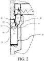
- FIG. 2 is a sectional view of a dispenser system installed in the door of a cooling appliance.
- the dispenser system 20 includes an ice delivery path P from the ice storage container to the dispenser cavity 21.
- the ice delivery path P includes an ice outlet 33 located on a terminal of the path and disposed above the dispenser cavity 21. Ice (such as an ice block or trash ice) is discharged into a receiving container located in the dispenser cavity 21 through the ice outlet 33.
- the ice delivery path P includes an ice channel 40 passing through the door 11. The ice is discharged from an outlet 41 of the ice channel 40 and moves towards the ice outlet 33.
- the outlet 41 may be selectively opened or closed by a closing component (not shown).
- the dispenser system generally further includes a water delivery channel (not shown), used for allocating drinking water stored in the cooling appliance to the dispenser cavity 21.
- a water delivery channel (not shown), used for allocating drinking water stored in the cooling appliance to the dispenser cavity 21.
- the dispenser system 20 further has a splash-proof component 30 disposed close to the outlet 41 of the ice channel 40.
- the splash-proof component 30 is installed inside the door through an installation frame 23, used for ice discharged from the outlet 41 to pass through, and leading the ice to a container placed in the dispenser cavity 21.
- the splash-proof component 30 includes an installation part and a buffering part.
- the buffering part is approximately in an inverted cone shape. Such a shape is capable of restricting ice from spreading and splashing around after being discharged, so that the ice can enter the container (not shown) in the dispenser cavity 21 more accurately.
- the buffering part has a circular ice outlet 33 located at the bottom and used for ice to pass through to enter the dispenser cavity 21, and an ice inlet 22 at the top and more close to the outlet 41 of the ice channel 40.
- the installation part is a circular ring formed by a top portion of the buffering part radially extending outwards, and is connected to the installation frame 23 through a post-forming process. It should be understood that, the installation part of the splash-proof component 30 may be connected to the installation frame 23 through other known connection methods such as adhesives and pressing.
- the splash-proof component 30 is made of a resilient material. Compared with a splash-proof component 30 in the prior art that is generally made of a rigid material, the splash-proof component 30 herein absorbs a part of or even all kinetic energy of ice when ice hits the splash-proof component 30, thereby avoiding irregular splashing of the ice as much as possible, so that the ice slows down to pass through the ice outlet 33 and enters the dispenser cavity 21. In other embodiments, it is feasible that only the buffering part of the splash-proof component 30 is made of a resilient material, and the installation part is made of another material.
- the resilient material may include a flexible material, a deformable material, or any material that help better absorption of kinetic energy of ice, such as synthetic rubber, preferably, silicon rubber, polyvinyl chloride (PVC) rubber, neoprene rubber, or a combination thereof.
- synthetic rubber preferably, silicon rubber, polyvinyl chloride (PVC) rubber, neoprene rubber, or a combination thereof.
- PVC polyvinyl chloride
- the splash-proof component 30 may be made of another material.
- the deformable buffering part that is, several elastic sheets, elaborated in the following
- the ice outlet 33 of the splash-proof component 30 is expandable. Compared with a fixed opening in the prior art, a smaller initial radial size may be set for the ice outlet 33, so that the buffering part 31 of the splash-proof component 30 can also effectively buffer smaller-sized ice.
- a slit 31 is disposed on the buffering part of the splash-proof component 30.
- the slit 31 extends from the ice outlet 33 to the installation part, without passing through the installation part.
- an extension line of the slit 31 passes through the center of the splash-proof component 30.
- an initial radial size of the ice outlet 33 may be 0. That is, in this case, the slit 31 passes through the center of the splash-proof component 30.
- the number of the slits is 3 or 4, equally dividing the buffering part into several elastic sheets 32.
- the dispenser system is further disposed with a water outlet 50, in communication with a liquid delivery channel (not shown), to allocate liquid into the dispenser cavity 21.
- the ice inlet 22 of the splash-proof component 30 has a first radial size ⁇ 1
- the ice outlet 33 of the splash-proof component 30 has an initial radial size ⁇ 2 and an expansion radial size ⁇ 3.
- the initial radial size ⁇ 2 of the opening may be set to be relatively small.
- a ratio of the initial radial size ⁇ 2 to the first radial size ⁇ 1 is less than or equal to 1/2, preferably, between 1/3 and 3/8.
- the initial radial size ⁇ 2 of the ice outlet 33 is less than or equal to 22 mm, such as 22 mm; and the first radial size ⁇ 1 is 62 mm.
- one end of the slit 31 is closed and the other end is open, and a cut angle ang is formed at the closed end.
- each elastic sheet 32 of the buffering part when ice enters from the ice inlet 22 of the splash-proof component 30 and then is discharged through the ice outlet 33, each elastic sheet 32 of the buffering part is bent and deformed due to an ice impact, and a distance between the adjacent elastic sheets becomes larger. In this case, an opening formed at a bottom of each elastic sheet 32 expands, so that the value of the expansion radial size ⁇ 3 may reach up to 60 mm; the cut angle ang becomes larger because the distance between the adjacent elastic sheets becomes larger. Since the buffering part is made of a resilient material, when ice passes through the ice outlet 33, each elastic sheet 32 of the buffering part restores to an original state. Correspondingly, the size of the ice outlet 33 restores to the initial radial size ⁇ 2, and the cut angle ang also restores to an original angle. In this embodiment, the cut angle is set to 0 when no ice passes through.
- An angle between a surface defined by the outlet 41 of the ice channel 40 and a surface defined by the ice inlet 22 of the splash-proof component 30 is an acute angle, which ensures that under the action of inertia, ice smoothly enters the ice inlet 22 of the splash-proof component 30 at a relatively accurate angle.
- a smaller ice outlet 33 may be disposed.
- the several elastic sheets (that is, the buffering part) forming the ice outlet 33 are made of a resilient material, and therefore are expandable. Then the splash-proof component 30 can properly adjust the size of the ice outlet 33 according to the size of ice passing through and the amount of ice passing through in a unit time, to achieve a relatively desirable dispenser rate.
- the overall splash-proof component 30 may generally be set to a shape that gradually narrows from top to bottom.
- the splash-proof component 30 is preferably set to an inverted cone shape. Since the splash-proof component 30 is disposed in the dispenser cavity 21, the disposition of the inverted cone shape not only implements the foregoing substantial functions, but also fulfills aesthetic needs of people.
- the ice outlet 33 is jointly restricted by lower edges of the elastic sheets 32.
- several deformable elastic sheets may be directly disposed in the ice outlet 33 to directly form the buffering part.
- the elastic sheets When ice passes through the ice outlet, the elastic sheets are deformed to expand/open the ice outlet and absorb at least one part of kinetic energy of ice, and the ice falls into the receiving container through the expanded ice outlet.
- the advantage of using the elastic sheets located in the ice outlet to directly form the splash-proof component lies in that, by directly disposing the ice outlet on an upper wall of the dispenser cavity, the splash-proof component obviously extending into the dispenser cavity shown in FIG. 3 to FIG. 6 may be saved.
- the cooling appliance 100 adopts the dispenser system 20 described in the foregoing embodiments, and can allocate ice and liquid without opening the door of the cooling appliance, which is convenient for use.
- the splash-proof component 30 is disposed, which can effectively reduce overhigh kinetic energy of ice due to inertia of ice to prevent the ice from spreading and splashing, and accurately and safely allocate ice of different sizes and of different flows into the container in the dispenser cavity 21.
- the dispenser system 20 is embedded in the door 11, which does not bring any redundant volume to refrigerators, thereby being practical and convenient.
Landscapes
- Engineering & Computer Science (AREA)
- Physics & Mathematics (AREA)
- Mechanical Engineering (AREA)
- Thermal Sciences (AREA)
- General Engineering & Computer Science (AREA)
- Chemical & Material Sciences (AREA)
- Combustion & Propulsion (AREA)
- Devices For Dispensing Beverages (AREA)
- Devices That Are Associated With Refrigeration Equipment (AREA)
Description
- The present invention relates to a cooling appliance and an dispenser system used for the cooling appliance, and in particular, to a cooling appliance capable of allocating ice and liquid and an dispenser system used for the cooling system.
- In the prior art, a cooling appliance with an dispenser system has been provided, such as a refrigerator. The dispenser system is generally disposed in a door of a cooling appliance, and is accessible outside the door, for a user to place containers. The dispenser system includes an ice channel and a liquid delivery channel, capable of selectively allocating liquid or ice made in the cooling appliance to the containers, so that the user can obtain ice or liquid, such as water, without opening the door of the cooling appliance, thereby bringing convenience to the lives of people.
- Generally, in the dispenser system of a cooling appliance, a splash-proof component is disposed close to an outlet of the ice channel, used for controlling an ice dispenser direction. The splash-proof component is generally made of a rigid material. Ice has great kinetic energy when falling to the outlet through the ice channel, and then hits the splash-proof component, resulting in irregular changes of a direction of kinetic energy of ice, thereby causing ice splashing, resulting in that the ice may not be accurately allocated to a container. In addition, ice with high kinetic energy may possibly bring potential safety risks to a user when taking ice.
-
US 2 997 860 A discloses an ice making system in which a gate at the bottom of an ice compartment is formed by a hydraulically expandable hollow annular member. When the member is inflated, the gate is closed. When the liquid is withdrawn from it the member collapses, allowing ice pellets to flow out. -
JP 2009 222252 A -
WO 2008/084973 A1 discloses a refrigerator comprising an ice duct, a downstream portion of which is displaceable. A guide portion for supplying ice to said downstream portion regardless of its position may be formed of a flexible material. - An objective of the present invention is to provide an dispenser system used for a cooling appliance, capable of reducing ice splashing during ice dispenser.
- Another objective of the present invention is to provide a cooling appliance that adopts the foregoing dispenser system.
- In order to achieve one of the foregoing objectives, the present invention provides an dispenser system used for a cooling appliance, as defined in claim 1.
- As a further improvement to the present invention, the resilient material includes synthetic rubber.
- As a further improvement to the present invention, the resilient material is selected from silicon rubber, or polyvinyl chloride (PVC) rubber, or neoprene rubber, or a combination thereof.
- As a further improvement to the present invention, the splash-proof component has an expandable opening allowing ice to pass through.
- As a further improvement to the present invention, the opening is circular, having an initial radial size and an expansion radial size.
- As a further improvement to the present invention, the initial radial size is less than or equal to 22 mm.
- As a further improvement to the present invention, the expansion radial size ranges from 22 mm to 60 mm.
- As a further improvement to the present invention, the buffering part further has a circular ice inlet, the ice inlet has a first radial size, and a ratio of the initial radial size to the first radial size is less than or equal to 1/2, particularly between 1/3 and 3/8.
- As a further improvement to the present invention, the slit or an extension line of the slit passes through the center of the splash-proof component.
- As a further improvement to the present invention, one end of the slit is closed and the other end is open, and a cut angle is formed at the closed end of the slit; the cut angle becomes larger when the ice passes through, and restores after the ice passes through.
- In order to fulfill another objective of the present invention, the present invention further provides a cooling appliance, including:
- a heat insulation cabinet, in which a storage chamber is formed; and
- a door, which cooperates with the heat insulation cabinet to open or close the storage chamber.
- The cooling appliance further includes the dispenser system according to any item of the above invention content located on the door.
- The beneficial effects of the present invention are as follows: the splash-proof component of the dispenser system is disposed with a buffering part made of a resilient material; therefore, when ice falls through the buffering part, the buffering part absorbs a part of kinetic energy of ice, to slow down a falling speed of the ice, so as to smoothly leading the ice to the corresponding container.
-
-
FIG. 1 is a schematic three-dimensional diagram of a specific embodiment of a cooling appliance according to the present invention; -
FIG. 2 is a schematic sectional diagram of a dispenser system of a cooling appliance and an ice-making system disposed in a cooling appliance; -
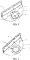
FIG. 3 is a schematic three-dimensional diagram of a bottom view of a splash-proof component and an installation frame to which the splash-proof component is connected in a dispenser system of the cooling appliance shown inFIG. 1 ; -
FIG. 4 is similar toFIG. 3 , in which an ice outlet of a buffering part of the splash-proof component is in expansion state; -
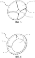
FIG. 5 is a schematic three-dimensional diagram of a top view of the splash-proof component of the dispenser system shown inFIG. 3 ; -
FIG. 6 is similar toFIG. 5 , in which an ice outlet of a buffering part of a splash-proof component is in expansion state; -
FIG. 7 is a schematic sectional diagram of a splash-proof component shown inFIG. 5 ; -
FIG. 8 is a schematic sectional diagram of the splash-proof component shown inFIG. 6 ; -
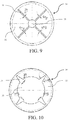
FIG. 9 is a top view of the splash-proof component shown inFIG. 5 ; -
FIG. 10 is a top view of the splash-proof component shown inFIG. 6 ; and -
FIG. 11 is a front view of a splash-proof component and an installation frame shown inFIG. 2 . - The present invention is described in detail in the following with reference to the embodiments shown in the accompanying drawings. However, these embodiments do not limit the present invention. All structural, methodological and functional changes made by persons of ordinary skill in the art according to these embodiments should fall within the protection scope of the present invention.
-
FIG. 1 illustrates a specific embodiment of a cooling appliance according to the present invention. In this embodiment, thecooling appliance 100 includes: aheat insulation cabinet 10, in which a storage chamber (not shown) is formed; and adoor 11, including, in this embodiment, a pair of double doors that is pivotally installed on theheat insulation cabinet 10 through hinges (not shown), cooperating with theheat insulation cabinet 10 to selectively open or close the storage chamber. - As a conventional cooling appliance, the storage chamber in this embodiment may also include a freezing chamber and a refrigerating chamber. The
cooling appliance 100 further includes adispenser system 20, where thedispenser system 20 may be used for allocating liquid (such as water) and ice in an ice storage container (not shown) of thecooling appliance 100 to adispenser cavity 21. In this embodiment, thedispenser cavity 21 is formed by recessing an outer surface of thedoor 11 inwards. -
FIG. 2 is a sectional view of a dispenser system installed in the door of a cooling appliance. Referring toFIG. 2 , thedispenser system 20 includes an ice delivery path P from the ice storage container to thedispenser cavity 21. The ice delivery path P includes anice outlet 33 located on a terminal of the path and disposed above thedispenser cavity 21. Ice (such as an ice block or trash ice) is discharged into a receiving container located in thedispenser cavity 21 through theice outlet 33. In this alternative embodiment, not being part of the present invention, the ice delivery path P includes anice channel 40 passing through thedoor 11. The ice is discharged from anoutlet 41 of theice channel 40 and moves towards theice outlet 33. Theoutlet 41 may be selectively opened or closed by a closing component (not shown). - The dispenser system generally further includes a water delivery channel (not shown), used for allocating drinking water stored in the cooling appliance to the
dispenser cavity 21. An dispenser mechanism of ice and water is known by persons of ordinary skill in the art, and the details are not described herein again. - Referring to
FIG. 3 to FIG. 10 , thedispenser system 20 further has a splash-proof component 30 disposed close to theoutlet 41 of theice channel 40. In this embodiment of the present invention, the splash-proof component 30 is installed inside the door through aninstallation frame 23, used for ice discharged from theoutlet 41 to pass through, and leading the ice to a container placed in thedispenser cavity 21. - In this embodiment, the splash-
proof component 30 includes an installation part and a buffering part. The buffering part is approximately in an inverted cone shape. Such a shape is capable of restricting ice from spreading and splashing around after being discharged, so that the ice can enter the container (not shown) in thedispenser cavity 21 more accurately. The buffering part has acircular ice outlet 33 located at the bottom and used for ice to pass through to enter thedispenser cavity 21, and anice inlet 22 at the top and more close to theoutlet 41 of theice channel 40. The installation part is a circular ring formed by a top portion of the buffering part radially extending outwards, and is connected to theinstallation frame 23 through a post-forming process. It should be understood that, the installation part of the splash-proof component 30 may be connected to theinstallation frame 23 through other known connection methods such as adhesives and pressing. - In this embodiment, the splash-
proof component 30 is made of a resilient material. Compared with a splash-proof component 30 in the prior art that is generally made of a rigid material, the splash-proof component 30 herein absorbs a part of or even all kinetic energy of ice when ice hits the splash-proof component 30, thereby avoiding irregular splashing of the ice as much as possible, so that the ice slows down to pass through theice outlet 33 and enters thedispenser cavity 21. In other embodiments, it is feasible that only the buffering part of the splash-proof component 30 is made of a resilient material, and the installation part is made of another material. The resilient material may include a flexible material, a deformable material, or any material that help better absorption of kinetic energy of ice, such as synthetic rubber, preferably, silicon rubber, polyvinyl chloride (PVC) rubber, neoprene rubber, or a combination thereof. It should be understood that, in a replacement embodiment, the splash-proof component 30 may be made of another material. For example, the deformable buffering part (that is, several elastic sheets, elaborated in the following) may also be made of sheet metal or plastic tabs/films easy to be bent. - Referring to
FIG. 3 to FIG. 6 , in this embodiment, theice outlet 33 of the splash-proof component 30 is expandable. Compared with a fixed opening in the prior art, a smaller initial radial size may be set for theice outlet 33, so that thebuffering part 31 of the splash-proof component 30 can also effectively buffer smaller-sized ice. - In this embodiment, a
slit 31 is disposed on the buffering part of the splash-proof component 30. Theslit 31 extends from theice outlet 33 to the installation part, without passing through the installation part. Preferably, an extension line of theslit 31 passes through the center of the splash-proof component 30. Persons skilled in the art may easily think of that, an initial radial size of theice outlet 33 may be 0. That is, in this case, theslit 31 passes through the center of the splash-proof component 30. - According to the present invention, the number of the slits is 3 or 4, equally dividing the buffering part into several
elastic sheets 32. - The dispenser system is further disposed with a
water outlet 50, in communication with a liquid delivery channel (not shown), to allocate liquid into thedispenser cavity 21. - Referring to
FIG. 7 and FIG. 8 , in this embodiment, theice inlet 22 of the splash-proof component 30 has a first radial size Φ1, and theice outlet 33 of the splash-proof component 30 has an initial radial size Φ2 and an expansion radial size Φ3. As mentioned above, since theice outlet 33 is expandable, the initial radial size Φ2 of the opening may be set to be relatively small. For example, a ratio of the initial radial size Φ2 to the first radial size Φ1 is less than or equal to 1/2, preferably, between 1/3 and 3/8. In this embodiment, the initial radial size Φ2 of theice outlet 33 is less than or equal to 22 mm, such as 22 mm; and the first radial size Φ1 is 62 mm. - Referring to
FIG. 9 and FIG. 10 , one end of theslit 31 is closed and the other end is open, and a cut angle ang is formed at the closed end. - In this embodiment, when ice enters from the
ice inlet 22 of the splash-proof component 30 and then is discharged through theice outlet 33, eachelastic sheet 32 of the buffering part is bent and deformed due to an ice impact, and a distance between the adjacent elastic sheets becomes larger. In this case, an opening formed at a bottom of eachelastic sheet 32 expands, so that the value of the expansion radial size Φ3 may reach up to 60 mm; the cut angle ang becomes larger because the distance between the adjacent elastic sheets becomes larger. Since the buffering part is made of a resilient material, when ice passes through theice outlet 33, eachelastic sheet 32 of the buffering part restores to an original state. Correspondingly, the size of theice outlet 33 restores to the initial radial size Φ2, and the cut angle ang also restores to an original angle. In this embodiment, the cut angle is set to 0 when no ice passes through. - An angle between a surface defined by the
outlet 41 of theice channel 40 and a surface defined by theice inlet 22 of the splash-proof component 30 is an acute angle, which ensures that under the action of inertia, ice smoothly enters theice inlet 22 of the splash-proof component 30 at a relatively accurate angle. - As mentioned above, in the prior art, to minimize the possibility of ice splashing when ice passes through the splash-
proof component 30, asmaller ice outlet 33 may be disposed. Preferably, the several elastic sheets (that is, the buffering part) forming theice outlet 33 are made of a resilient material, and therefore are expandable. Then the splash-proof component 30 can properly adjust the size of theice outlet 33 according to the size of ice passing through and the amount of ice passing through in a unit time, to achieve a relatively desirable dispenser rate. - Referring to
FIG. 7, FIG. 8 andFIG. 11 , the overall splash-proof component 30 may generally be set to a shape that gradually narrows from top to bottom. In this embodiment, the splash-proof component 30 is preferably set to an inverted cone shape. Since the splash-proof component 30 is disposed in thedispenser cavity 21, the disposition of the inverted cone shape not only implements the foregoing substantial functions, but also fulfills aesthetic needs of people. - In the foregoing embodiments, the
ice outlet 33 is jointly restricted by lower edges of theelastic sheets 32. However, in a replacement embodiment, several deformable elastic sheets may be directly disposed in theice outlet 33 to directly form the buffering part. When ice passes through the ice outlet, the elastic sheets are deformed to expand/open the ice outlet and absorb at least one part of kinetic energy of ice, and the ice falls into the receiving container through the expanded ice outlet. The advantage of using the elastic sheets located in the ice outlet to directly form the splash-proof component lies in that, by directly disposing the ice outlet on an upper wall of the dispenser cavity, the splash-proof component obviously extending into the dispenser cavity shown inFIG. 3 to FIG. 6 may be saved. - The cooling
appliance 100 adopts thedispenser system 20 described in the foregoing embodiments, and can allocate ice and liquid without opening the door of the cooling appliance, which is convenient for use. In addition, the splash-proof component 30 is disposed, which can effectively reduce overhigh kinetic energy of ice due to inertia of ice to prevent the ice from spreading and splashing, and accurately and safely allocate ice of different sizes and of different flows into the container in thedispenser cavity 21. Moreover, thedispenser system 20 is embedded in thedoor 11, which does not bring any redundant volume to refrigerators, thereby being practical and convenient. - For persons skilled in the art, obviously, the present invention is not limited to the foregoing details of exemplary embodiments, and can be implemented through other specific forms without departing from the spirit or basic characteristics of the present invention. Therefore, seen from whichever point, the embodiments should be construed as exemplary, but not restrictive. The scope of the present invention is subject to the appended claims but not the foregoing description. Therefore, all changes falling within the meanings and scope of the equivalent requirements of the claims should be included in the preset invention. Any mark of the accompanying drawings in the claims should not be regarded as limitation to the related claims.
- Besides, it should be understood that, although the specification is described according to the embodiments, each embodiment does not include merely one independent technical solution. The narration mode of the specification is for the sake of clarity. Persons skilled in the art should regard the specification as a whole. The technical solutions of the embodiments may be properly combined, to form other embodiments that may be understood by persons skilled in the art.
Claims (11)
- A dispenser system (20) used for a cooling appliance (100), the dispenser system (20) comprising an ice delivery path (P) and a splash-proof component (30) located in the ice delivery path (P), and the splash-proof component (30) comprising a buffering part for absorbing at least a part of kinetic energy of ice when the ice passes through, wherein the buffering part is made of a flexible material, characterized in that the buffering part is divided into several elastic sheets (32) by three or four slits (31), equally dividing the buffering part.
- The dispenser system (20) according to claim 1, characterized in that: the resilient material comprises synthetic rubber.
- The dispenser system (20) according to claim 1, characterized in that: the resilient material is selected from silicon rubber, or polyvinyl chloride (PVC) rubber, or neoprene rubber, or a combination thereof.
- The dispenser system (20) according to claim 1, characterized in that: the buffering part of splash-proof component (30) has an expandable opening (33) allowing the ice to pass through.
- The dispenser system (20) according to claim 4, characterized in that: the opening (33) is circular, having an initial radial size and an expansion radial size.
- The dispenser system (20) according to claim 5, characterized in that: the initial radial size is less than or equal to 22 mm.
- The dispenser system (20) according to claim 5, characterized in that: the expansion radial size ranges from 22 mm to 60 mm.
- The dispenser system (20) according to claim 5, characterized in that: the buffering part further has a circular ice inlet (22), the ice inlet (22) has a first radial size, and
a ratio of the initial radial size to the first radial size is less than or equal to 1/2, particularly between 1/3 and 3/8. - The dispenser system (20) according to claim 1,
characterized in that: the slits (31) or extension lines of the slits (31) pass through the center of the splash-proof component. - The dispenser system (20) according to claim 1, characterized in that: one end of the slit (31) is closed and the other end is open, and a cut angle (ang) is formed at the closed end of the slit; the cut angle (ang) becomes larger when the ice passes through, and restores after the ice passes through.
- A cooling appliance (100), comprising: a heat insulation cabinet (10), in which a storage chamber is formed; and a door (11), which cooperates with the heat insulation cabinet (10) to open or close the storage chamber, characterized in that, the cooling appliance (100) further comprises a dispenser system (20) according to any one of above claims, the dispenser system (20) being located on the door (11).
Priority Applications (1)
| Application Number | Priority Date | Filing Date | Title |
|---|---|---|---|
| PL12756761T PL2761239T3 (en) | 2011-09-27 | 2012-09-13 | Cooling appliance and dispenser system used for cooling appliance |
Applications Claiming Priority (2)
| Application Number | Priority Date | Filing Date | Title |
|---|---|---|---|
| CN201110303120.5A CN103017462B (en) | 2011-09-27 | 2011-09-27 | Refrigerating appliance and the distribution system for refrigerating appliance |
| PCT/EP2012/067985 WO2013045281A2 (en) | 2011-09-27 | 2012-09-13 | Cooling appliance and dispenser system used for cooling appliance |
Publications (2)
| Publication Number | Publication Date |
|---|---|
| EP2761239A2 EP2761239A2 (en) | 2014-08-06 |
| EP2761239B1 true EP2761239B1 (en) | 2016-12-28 |
Family
ID=46829795
Family Applications (1)
| Application Number | Title | Priority Date | Filing Date |
|---|---|---|---|
| EP12756761.8A Not-in-force EP2761239B1 (en) | 2011-09-27 | 2012-09-13 | Cooling appliance and dispenser system used for cooling appliance |
Country Status (5)
| Country | Link |
|---|---|
| US (1) | US20150143837A1 (en) |
| EP (1) | EP2761239B1 (en) |
| CN (1) | CN103017462B (en) |
| PL (1) | PL2761239T3 (en) |
| WO (1) | WO2013045281A2 (en) |
Families Citing this family (4)
| Publication number | Priority date | Publication date | Assignee | Title |
|---|---|---|---|---|
| US9874386B2 (en) | 2015-05-05 | 2018-01-23 | Haier Us Appliance Solutions, Inc. | Refrigerator appliance |
| CN107940850B (en) * | 2017-05-05 | 2021-10-29 | 海尔智家股份有限公司 | an ice crusher |
| US10989459B2 (en) * | 2018-06-18 | 2021-04-27 | Haier Us Appliance Solutions, Inc. | Refrigerator appliance and ice dispenser defining a liquid outlet |
| US12560376B2 (en) * | 2023-12-07 | 2026-02-24 | Haier Us Appliance Solutions, Inc. | Refrigerator appliance and adjustable area dispenser |
Family Cites Families (14)
| Publication number | Priority date | Publication date | Assignee | Title |
|---|---|---|---|---|
| US2997860A (en) * | 1956-09-07 | 1961-08-29 | Muffly Glenn | Ice making and refrigerating systems |
| US2940678A (en) * | 1958-06-16 | 1960-06-14 | Gen Motors Corp | Ice cracking device |
| US3163371A (en) * | 1963-01-24 | 1964-12-29 | Splash guard for food waste disposer | |
| US3640088A (en) * | 1970-06-03 | 1972-02-08 | Gen Electric | Household refrigerator including exterior ice service |
| US3718237A (en) * | 1971-12-15 | 1973-02-27 | Gen Electric | Closure means for through-the-door ice service for household refrigerators |
| US4008740A (en) * | 1974-09-03 | 1977-02-22 | Chermack Robert W | Dispensing apparatus for filling drinking containers |
| US3934691A (en) * | 1974-12-06 | 1976-01-27 | General Electric Company | Ice dispensing system of a refrigerator-freezer |
| JP2002310549A (en) * | 2001-04-13 | 2002-10-23 | Rika Kuramoto | Refrigerator with automatic ice maker |
| KR20070075670A (en) * | 2006-01-14 | 2007-07-24 | 삼성전자주식회사 | Refrigerator and its control method |
| KR20080065435A (en) * | 2007-01-09 | 2008-07-14 | 엘지전자 주식회사 | Ice Guide for Refrigerator |
| JP2009222252A (en) * | 2008-03-13 | 2009-10-01 | Hitachi Appliances Inc | Refrigerator with ice maker |
| DE102008041670A1 (en) * | 2008-08-28 | 2010-03-04 | BSH Bosch und Siemens Hausgeräte GmbH | Dispenser for a refrigerator |
| JP5343467B2 (en) * | 2008-09-12 | 2013-11-13 | 富士電機株式会社 | Ice supply nozzle structure and pipe structure |
| KR101513628B1 (en) * | 2008-09-30 | 2015-04-20 | 엘지전자 주식회사 | A refrigerator having a dispenser |
-
2011
- 2011-09-27 CN CN201110303120.5A patent/CN103017462B/en not_active Expired - Fee Related
-
2012
- 2012-09-13 WO PCT/EP2012/067985 patent/WO2013045281A2/en not_active Ceased
- 2012-09-13 PL PL12756761T patent/PL2761239T3/en unknown
- 2012-09-13 EP EP12756761.8A patent/EP2761239B1/en not_active Not-in-force
- 2012-09-13 US US14/347,734 patent/US20150143837A1/en not_active Abandoned
Non-Patent Citations (1)
| Title |
|---|
| None * |
Also Published As
| Publication number | Publication date |
|---|---|
| WO2013045281A2 (en) | 2013-04-04 |
| CN103017462B (en) | 2017-08-11 |
| US20150143837A1 (en) | 2015-05-28 |
| PL2761239T3 (en) | 2017-06-30 |
| EP2761239A2 (en) | 2014-08-06 |
| CN103017462A (en) | 2013-04-03 |
| WO2013045281A3 (en) | 2013-06-13 |
Similar Documents
| Publication | Publication Date | Title |
|---|---|---|
| USRE50167E1 (en) | Refrigerator including multiple storage compartments | |
| US20150143837A1 (en) | Cooling appliance and dispenser system used for cooling appliance | |
| US20100043478A1 (en) | Ice bank and refrigerator | |
| CN203534032U (en) | Drainpipe used for refrigerator, and refrigerator | |
| JP2017508125A (en) | Multi-function room and refrigerator | |
| CN105546927A (en) | Drawer assembly and refrigerator with drawer assembly | |
| US10429115B2 (en) | Refrigerator | |
| US20170167780A1 (en) | Refrigerator | |
| WO2013107662A3 (en) | Refrigeration device with door-mounted user interface | |
| CN202470591U (en) | Refrigerator with automatic pop-open door body | |
| CN102494476A (en) | Refrigerator | |
| CN108413667B (en) | A kind of crushed ice structure for refrigerator and refrigerator having the same | |
| CN103017461B (en) | Refrigerating appliance and the distribution system for refrigerating appliance | |
| EP3037748B1 (en) | Refrigerator | |
| CN107550344A (en) | A kind of flavouring box for kitchen use | |
| CN102538351A (en) | Counter internal door for refrigerator and refrigerator with counter internal door | |
| CN208510703U (en) | Electric pressure cooker | |
| CN205243250U (en) | Attenuator, gas elasticity hinge and freezer | |
| KR20150058731A (en) | Dispenser of Refrigerator | |
| CN204027129U (en) | Refrigerator | |
| CN209991648U (en) | Refrigerating and freezing device | |
| EP3951289B1 (en) | Refrigerator | |
| CN221099105U (en) | Water receiving box structure and constant temperature and humidity equipment | |
| CN102564037A (en) | Shelf component and refrigerator with shelf component | |
| WO2023274021A1 (en) | Refrigeration apparatus |
Legal Events
| Date | Code | Title | Description |
|---|---|---|---|
| PUAI | Public reference made under article 153(3) epc to a published international application that has entered the european phase |
Free format text: ORIGINAL CODE: 0009012 |
|
| 17P | Request for examination filed |
Effective date: 20140428 |
|
| AK | Designated contracting states |
Kind code of ref document: A2 Designated state(s): AL AT BE BG CH CY CZ DE DK EE ES FI FR GB GR HR HU IE IS IT LI LT LU LV MC MK MT NL NO PL PT RO RS SE SI SK SM TR |
|
| RAP1 | Party data changed (applicant data changed or rights of an application transferred) |
Owner name: BSH BOSCH UND SIEMENS HAUSGERAETE GMBH |
|
| DAX | Request for extension of the european patent (deleted) | ||
| RAP1 | Party data changed (applicant data changed or rights of an application transferred) |
Owner name: BSH HAUSGERAETE GMBH |
|
| GRAP | Despatch of communication of intention to grant a patent |
Free format text: ORIGINAL CODE: EPIDOSNIGR1 |
|
| INTG | Intention to grant announced |
Effective date: 20160810 |
|
| GRAS | Grant fee paid |
Free format text: ORIGINAL CODE: EPIDOSNIGR3 |
|
| GRAA | (expected) grant |
Free format text: ORIGINAL CODE: 0009210 |
|
| AK | Designated contracting states |
Kind code of ref document: B1 Designated state(s): AL AT BE BG CH CY CZ DE DK EE ES FI FR GB GR HR HU IE IS IT LI LT LU LV MC MK MT NL NO PL PT RO RS SE SI SK SM TR |
|
| REG | Reference to a national code |
Ref country code: GB Ref legal event code: FG4D |
|
| REG | Reference to a national code |
Ref country code: CH Ref legal event code: EP |
|
| REG | Reference to a national code |
Ref country code: AT Ref legal event code: REF Ref document number: 857654 Country of ref document: AT Kind code of ref document: T Effective date: 20170115 |
|
| REG | Reference to a national code |
Ref country code: IE Ref legal event code: FG4D |
|
| REG | Reference to a national code |
Ref country code: DE Ref legal event code: R096 Ref document number: 602012027113 Country of ref document: DE |
|
| PG25 | Lapsed in a contracting state [announced via postgrant information from national office to epo] |
Ref country code: LV Free format text: LAPSE BECAUSE OF FAILURE TO SUBMIT A TRANSLATION OF THE DESCRIPTION OR TO PAY THE FEE WITHIN THE PRESCRIBED TIME-LIMIT Effective date: 20161228 |
|
| REG | Reference to a national code |
Ref country code: LT Ref legal event code: MG4D |
|
| PG25 | Lapsed in a contracting state [announced via postgrant information from national office to epo] |
Ref country code: LT Free format text: LAPSE BECAUSE OF FAILURE TO SUBMIT A TRANSLATION OF THE DESCRIPTION OR TO PAY THE FEE WITHIN THE PRESCRIBED TIME-LIMIT Effective date: 20161228 Ref country code: NO Free format text: LAPSE BECAUSE OF FAILURE TO SUBMIT A TRANSLATION OF THE DESCRIPTION OR TO PAY THE FEE WITHIN THE PRESCRIBED TIME-LIMIT Effective date: 20170328 Ref country code: GR Free format text: LAPSE BECAUSE OF FAILURE TO SUBMIT A TRANSLATION OF THE DESCRIPTION OR TO PAY THE FEE WITHIN THE PRESCRIBED TIME-LIMIT Effective date: 20170329 Ref country code: SE Free format text: LAPSE BECAUSE OF FAILURE TO SUBMIT A TRANSLATION OF THE DESCRIPTION OR TO PAY THE FEE WITHIN THE PRESCRIBED TIME-LIMIT Effective date: 20161228 |
|
| REG | Reference to a national code |
Ref country code: NL Ref legal event code: MP Effective date: 20161228 |
|
| REG | Reference to a national code |
Ref country code: AT Ref legal event code: MK05 Ref document number: 857654 Country of ref document: AT Kind code of ref document: T Effective date: 20161228 |
|
| PG25 | Lapsed in a contracting state [announced via postgrant information from national office to epo] |
Ref country code: FI Free format text: LAPSE BECAUSE OF FAILURE TO SUBMIT A TRANSLATION OF THE DESCRIPTION OR TO PAY THE FEE WITHIN THE PRESCRIBED TIME-LIMIT Effective date: 20161228 Ref country code: RS Free format text: LAPSE BECAUSE OF FAILURE TO SUBMIT A TRANSLATION OF THE DESCRIPTION OR TO PAY THE FEE WITHIN THE PRESCRIBED TIME-LIMIT Effective date: 20161228 Ref country code: HR Free format text: LAPSE BECAUSE OF FAILURE TO SUBMIT A TRANSLATION OF THE DESCRIPTION OR TO PAY THE FEE WITHIN THE PRESCRIBED TIME-LIMIT Effective date: 20161228 |
|
| PG25 | Lapsed in a contracting state [announced via postgrant information from national office to epo] |
Ref country code: NL Free format text: LAPSE BECAUSE OF FAILURE TO SUBMIT A TRANSLATION OF THE DESCRIPTION OR TO PAY THE FEE WITHIN THE PRESCRIBED TIME-LIMIT Effective date: 20161228 |
|
| PG25 | Lapsed in a contracting state [announced via postgrant information from national office to epo] |
Ref country code: IS Free format text: LAPSE BECAUSE OF FAILURE TO SUBMIT A TRANSLATION OF THE DESCRIPTION OR TO PAY THE FEE WITHIN THE PRESCRIBED TIME-LIMIT Effective date: 20170428 Ref country code: EE Free format text: LAPSE BECAUSE OF FAILURE TO SUBMIT A TRANSLATION OF THE DESCRIPTION OR TO PAY THE FEE WITHIN THE PRESCRIBED TIME-LIMIT Effective date: 20161228 Ref country code: RO Free format text: LAPSE BECAUSE OF FAILURE TO SUBMIT A TRANSLATION OF THE DESCRIPTION OR TO PAY THE FEE WITHIN THE PRESCRIBED TIME-LIMIT Effective date: 20161228 Ref country code: SK Free format text: LAPSE BECAUSE OF FAILURE TO SUBMIT A TRANSLATION OF THE DESCRIPTION OR TO PAY THE FEE WITHIN THE PRESCRIBED TIME-LIMIT Effective date: 20161228 Ref country code: CZ Free format text: LAPSE BECAUSE OF FAILURE TO SUBMIT A TRANSLATION OF THE DESCRIPTION OR TO PAY THE FEE WITHIN THE PRESCRIBED TIME-LIMIT Effective date: 20161228 |
|
| PG25 | Lapsed in a contracting state [announced via postgrant information from national office to epo] |
Ref country code: SM Free format text: LAPSE BECAUSE OF FAILURE TO SUBMIT A TRANSLATION OF THE DESCRIPTION OR TO PAY THE FEE WITHIN THE PRESCRIBED TIME-LIMIT Effective date: 20161228 Ref country code: AT Free format text: LAPSE BECAUSE OF FAILURE TO SUBMIT A TRANSLATION OF THE DESCRIPTION OR TO PAY THE FEE WITHIN THE PRESCRIBED TIME-LIMIT Effective date: 20161228 Ref country code: PT Free format text: LAPSE BECAUSE OF FAILURE TO SUBMIT A TRANSLATION OF THE DESCRIPTION OR TO PAY THE FEE WITHIN THE PRESCRIBED TIME-LIMIT Effective date: 20170428 Ref country code: BG Free format text: LAPSE BECAUSE OF FAILURE TO SUBMIT A TRANSLATION OF THE DESCRIPTION OR TO PAY THE FEE WITHIN THE PRESCRIBED TIME-LIMIT Effective date: 20170328 Ref country code: BE Free format text: LAPSE BECAUSE OF FAILURE TO SUBMIT A TRANSLATION OF THE DESCRIPTION OR TO PAY THE FEE WITHIN THE PRESCRIBED TIME-LIMIT Effective date: 20161228 Ref country code: ES Free format text: LAPSE BECAUSE OF FAILURE TO SUBMIT A TRANSLATION OF THE DESCRIPTION OR TO PAY THE FEE WITHIN THE PRESCRIBED TIME-LIMIT Effective date: 20161228 |
|
| REG | Reference to a national code |
Ref country code: DE Ref legal event code: R097 Ref document number: 602012027113 Country of ref document: DE |
|
| PGFP | Annual fee paid to national office [announced via postgrant information from national office to epo] |
Ref country code: IT Payment date: 20170926 Year of fee payment: 6 |
|
| PLBE | No opposition filed within time limit |
Free format text: ORIGINAL CODE: 0009261 |
|
| STAA | Information on the status of an ep patent application or granted ep patent |
Free format text: STATUS: NO OPPOSITION FILED WITHIN TIME LIMIT |
|
| PG25 | Lapsed in a contracting state [announced via postgrant information from national office to epo] |
Ref country code: DK Free format text: LAPSE BECAUSE OF FAILURE TO SUBMIT A TRANSLATION OF THE DESCRIPTION OR TO PAY THE FEE WITHIN THE PRESCRIBED TIME-LIMIT Effective date: 20161228 |
|
| PGFP | Annual fee paid to national office [announced via postgrant information from national office to epo] |
Ref country code: PL Payment date: 20170912 Year of fee payment: 6 Ref country code: TR Payment date: 20170911 Year of fee payment: 6 |
|
| 26N | No opposition filed |
Effective date: 20170929 |
|
| PGFP | Annual fee paid to national office [announced via postgrant information from national office to epo] |
Ref country code: DE Payment date: 20170930 Year of fee payment: 6 |
|
| PG25 | Lapsed in a contracting state [announced via postgrant information from national office to epo] |
Ref country code: SI Free format text: LAPSE BECAUSE OF FAILURE TO SUBMIT A TRANSLATION OF THE DESCRIPTION OR TO PAY THE FEE WITHIN THE PRESCRIBED TIME-LIMIT Effective date: 20161228 |
|
| REG | Reference to a national code |
Ref country code: CH Ref legal event code: PL |
|
| GBPC | Gb: european patent ceased through non-payment of renewal fee |
Effective date: 20170913 |
|
| PG25 | Lapsed in a contracting state [announced via postgrant information from national office to epo] |
Ref country code: MC Free format text: LAPSE BECAUSE OF FAILURE TO SUBMIT A TRANSLATION OF THE DESCRIPTION OR TO PAY THE FEE WITHIN THE PRESCRIBED TIME-LIMIT Effective date: 20161228 |
|
| REG | Reference to a national code |
Ref country code: IE Ref legal event code: MM4A |
|
| PG25 | Lapsed in a contracting state [announced via postgrant information from national office to epo] |
Ref country code: LU Free format text: LAPSE BECAUSE OF NON-PAYMENT OF DUE FEES Effective date: 20170913 |
|
| REG | Reference to a national code |
Ref country code: FR Ref legal event code: ST Effective date: 20180531 |
|
| PG25 | Lapsed in a contracting state [announced via postgrant information from national office to epo] |
Ref country code: LI Free format text: LAPSE BECAUSE OF NON-PAYMENT OF DUE FEES Effective date: 20170930 Ref country code: CH Free format text: LAPSE BECAUSE OF NON-PAYMENT OF DUE FEES Effective date: 20170930 Ref country code: IE Free format text: LAPSE BECAUSE OF NON-PAYMENT OF DUE FEES Effective date: 20170913 Ref country code: GB Free format text: LAPSE BECAUSE OF NON-PAYMENT OF DUE FEES Effective date: 20170913 |
|
| PG25 | Lapsed in a contracting state [announced via postgrant information from national office to epo] |
Ref country code: FR Free format text: LAPSE BECAUSE OF NON-PAYMENT OF DUE FEES Effective date: 20171002 |
|
| PG25 | Lapsed in a contracting state [announced via postgrant information from national office to epo] |
Ref country code: MT Free format text: LAPSE BECAUSE OF NON-PAYMENT OF DUE FEES Effective date: 20170913 |
|
| REG | Reference to a national code |
Ref country code: DE Ref legal event code: R119 Ref document number: 602012027113 Country of ref document: DE |
|
| PG25 | Lapsed in a contracting state [announced via postgrant information from national office to epo] |
Ref country code: HU Free format text: LAPSE BECAUSE OF FAILURE TO SUBMIT A TRANSLATION OF THE DESCRIPTION OR TO PAY THE FEE WITHIN THE PRESCRIBED TIME-LIMIT; INVALID AB INITIO Effective date: 20120913 |
|
| PG25 | Lapsed in a contracting state [announced via postgrant information from national office to epo] |
Ref country code: DE Free format text: LAPSE BECAUSE OF NON-PAYMENT OF DUE FEES Effective date: 20190402 Ref country code: IT Free format text: LAPSE BECAUSE OF NON-PAYMENT OF DUE FEES Effective date: 20180913 |
|
| PG25 | Lapsed in a contracting state [announced via postgrant information from national office to epo] |
Ref country code: CY Free format text: LAPSE BECAUSE OF NON-PAYMENT OF DUE FEES Effective date: 20161228 |
|
| PG25 | Lapsed in a contracting state [announced via postgrant information from national office to epo] |
Ref country code: MK Free format text: LAPSE BECAUSE OF FAILURE TO SUBMIT A TRANSLATION OF THE DESCRIPTION OR TO PAY THE FEE WITHIN THE PRESCRIBED TIME-LIMIT Effective date: 20161228 |
|
| PG25 | Lapsed in a contracting state [announced via postgrant information from national office to epo] |
Ref country code: PL Free format text: LAPSE BECAUSE OF NON-PAYMENT OF DUE FEES Effective date: 20180913 |
|
| PG25 | Lapsed in a contracting state [announced via postgrant information from national office to epo] |
Ref country code: AL Free format text: LAPSE BECAUSE OF FAILURE TO SUBMIT A TRANSLATION OF THE DESCRIPTION OR TO PAY THE FEE WITHIN THE PRESCRIBED TIME-LIMIT Effective date: 20161228 |
|
| PG25 | Lapsed in a contracting state [announced via postgrant information from national office to epo] |
Ref country code: TR Free format text: LAPSE BECAUSE OF NON-PAYMENT OF DUE FEES Effective date: 20180913 |