EP2760269B1 - Quick-change blade system - Google Patents
Quick-change blade system Download PDFInfo
- Publication number
- EP2760269B1 EP2760269B1 EP12835259.8A EP12835259A EP2760269B1 EP 2760269 B1 EP2760269 B1 EP 2760269B1 EP 12835259 A EP12835259 A EP 12835259A EP 2760269 B1 EP2760269 B1 EP 2760269B1
- Authority
- EP
- European Patent Office
- Prior art keywords
- blade
- blade mount
- mount
- insertion slot
- disposed
- Prior art date
- Legal status (The legal status is an assumption and is not a legal conclusion. Google has not performed a legal analysis and makes no representation as to the accuracy of the status listed.)
- Not-in-force
Links
Images


Classifications
-
- A—HUMAN NECESSITIES
- A01—AGRICULTURE; FORESTRY; ANIMAL HUSBANDRY; HUNTING; TRAPPING; FISHING
- A01D—HARVESTING; MOWING
- A01D34/00—Mowers; Mowing apparatus of harvesters
- A01D34/01—Mowers; Mowing apparatus of harvesters characterised by features relating to the type of cutting apparatus
- A01D34/412—Mowers; Mowing apparatus of harvesters characterised by features relating to the type of cutting apparatus having rotating cutters
- A01D34/63—Mowers; Mowing apparatus of harvesters characterised by features relating to the type of cutting apparatus having rotating cutters having cutters rotating about a vertical axis
- A01D34/73—Cutting apparatus
- A01D34/733—Cutting-blade mounting means
-
- A—HUMAN NECESSITIES
- A01—AGRICULTURE; FORESTRY; ANIMAL HUSBANDRY; HUNTING; TRAPPING; FISHING
- A01D—HARVESTING; MOWING
- A01D34/00—Mowers; Mowing apparatus of harvesters
- A01D34/01—Mowers; Mowing apparatus of harvesters characterised by features relating to the type of cutting apparatus
- A01D34/412—Mowers; Mowing apparatus of harvesters characterised by features relating to the type of cutting apparatus having rotating cutters
- A01D34/63—Mowers; Mowing apparatus of harvesters characterised by features relating to the type of cutting apparatus having rotating cutters having cutters rotating about a vertical axis
- A01D34/64—Mowers; Mowing apparatus of harvesters characterised by features relating to the type of cutting apparatus having rotating cutters having cutters rotating about a vertical axis mounted on a vehicle, e.g. a tractor, or drawn by an animal or a vehicle
- A01D34/66—Mowers; Mowing apparatus of harvesters characterised by features relating to the type of cutting apparatus having rotating cutters having cutters rotating about a vertical axis mounted on a vehicle, e.g. a tractor, or drawn by an animal or a vehicle with two or more cutters
- A01D34/664—Disc cutter bars
-
- A—HUMAN NECESSITIES
- A01—AGRICULTURE; FORESTRY; ANIMAL HUSBANDRY; HUNTING; TRAPPING; FISHING
- A01D—HARVESTING; MOWING
- A01D34/00—Mowers; Mowing apparatus of harvesters
- A01D34/01—Mowers; Mowing apparatus of harvesters characterised by features relating to the type of cutting apparatus
- A01D34/412—Mowers; Mowing apparatus of harvesters characterised by features relating to the type of cutting apparatus having rotating cutters
- A01D34/63—Mowers; Mowing apparatus of harvesters characterised by features relating to the type of cutting apparatus having rotating cutters having cutters rotating about a vertical axis
- A01D34/81—Casings; Housings
-
- E—FIXED CONSTRUCTIONS
- E05—LOCKS; KEYS; WINDOW OR DOOR FITTINGS; SAFES
- E05C—BOLTS OR FASTENING DEVICES FOR WINGS, SPECIALLY FOR DOORS OR WINDOWS
- E05C19/00—Other devices specially designed for securing wings, e.g. with suction cups
- E05C19/10—Hook fastenings; Fastenings in which a link engages a fixed hook-like member
- E05C19/12—Hook fastenings; Fastenings in which a link engages a fixed hook-like member pivotally mounted around an axis
- E05C19/14—Hook fastenings; Fastenings in which a link engages a fixed hook-like member pivotally mounted around an axis with toggle action
Definitions
- the invention relates to a blade mount and a lawn care vehicle comprising a blade mount.
- Example embodiments generally relate to outdoor power equipment and, more particularly, some embodiments relate to a lawn mower with a blade assembly that has blades that can be quickly removed and/or replaced.
- Lawn care tasks are commonly performed using various tools and/or machines that are configured for the performance of corresponding specific tasks. Certain tasks, like grass cutting, are typically performed by lawn mowers. Lawn mowers themselves may have many different configurations to support the needs and budgets of consumers. Walk-behind lawn mowers are typically compact, have comparatively small engines and are relatively inexpensive. Meanwhile, at the other end of the spectrum, riding lawn mowers, such as lawn tractors, can be quite large. Riding lawn mowers can sometimes also be configured with various functional accessories (e.g., trailers, tillers and/or the like) in addition to grass cutting components. Riding lawn mowers provide the convenience of a riding vehicle as well as a typically larger cutting deck as compared to a walk-behind model.
- the cutting blades of a lawn mower are an important, but sometimes overlooked, component of the lawn mower.
- the sharpness of the lawn mower blade impacts the quality of cut achieved using the corresponding blade.
- a blade is not sharp, blades of grass may receive an uneven cut and the ends of the grass may tend to brown, leaving a less desirable appearance to the lawn and increasing susceptibility to some diseases. Meanwhile, using a sharp blade can achieve a cleaner cut that leaves a more appealing appearance to the cut lawn.
- Blade sharpening or replacement requires removal of the blade from the lawn mower.
- Some lawn mower operators may be intimidated by the prospect of removing the blades either due to their perception of the complexity or difficulty of the task or due to their perception of the likelihood that tools that they do not possess may be required to complete the task.
- the document US 5,036,654 discloses a blade mount for a lawn care vehicle with a blade mount base disposed to engage a rotatable shaft of the vehicle at the center of the mount.
- a blade insertion slot is arranged proximate to a distal end of the base and configured to enclose a portion of a blade.
- a blade engagement assembly disposed proximate to the base is provided to enable removal of a protruding member from the slot responsive to operation of the blade engagement assembly. The protruding member is biased to protrude into the slot to secure the blade within the slot then the blade engagement assembly is not operated to remove the member from the slot.
- Some example embodiments may provide a quick-change blade system that may allow users to make blade changes on a lawn mower relatively quickly and easily.
- some embodiments may provide for blade designs and corresponding mounting apparatuses that may enable operators to change blades with only very simple tools, or perhaps no tools at all.
- some example embodiments may provide for a blade change system that may be back fitted to existing lawn mowers.
- some embodiments may provide for mounting apparatuses that may be configured to attach to an existing cutting deck and enable the existing cutting deck to thereafter support the use of quick-change blades as described herein.
- Some example embodiments may improve the ability of operators to change blades quickly and easily. Operators may therefore take fuller advantage of the capabilities of their lawn mowers, and have a greater satisfaction with the performance of their lawn mowers.
- a lawn care vehicle as defined in claim 10 may include a cutting deck housing at least one blade, a rotatable shaft, and a blade mount operably coupled to the rotatable shaft.
- the blade mount includes at least one engagement slot configured to enclose at least a portion of the at least one blade.
- the blade mount further includes at least one protruding member disposed within the engagement slot to secure the at least one blade within the engagement slot responsive to insertion of the at least one blade into the engagement slot.
- a blade mount as defined in claim 1 is provided.
- the blade mount is configured to couple a blade to a rotatable shaft.
- the blade mount includes at least one engagement slot configured to enclose at least a portion of the blade, and at least one protruding member disposed within the engagement slot to secure the blade within the engagement slot responsive to insertion of the blade into the engagement slot.
- a cutting blade for a lawn mower is disclosed herein.
- the blade may include a top face, a bottom face, and at least one alignment slot forming a cutout portion of the blade passing from one of the top face or bottom face toward the other of the top face or the bottom face.
- the at least one alignment slot may be disposed spaced apart from an axis of rotation of the blade to receive a corresponding protruding member of a blade mount configured to hold the blade, via engagement of the protruding member with the at least one alignment slot, at a portion of the blade other than at the axis of rotation during rotation of the blade responsive to operation of the lawn mower.
- the quick-change mounting apparatuses described herein may be used to similarly couple other devices together.
- the mounting apparatuses described herein may be used to couple cutting elements to other types of lawn care equipment, such as trimmers, edgers, circular saws, chainsaws, and/or the like.
- the mounting apparatuses may also be used to couple rotary elements in devices other than lawn care equipment.
- the mounting apparatuses described herein may be used to attach fan blades to a fan.
- FIGs 1 to 14 do not form part of the invention but represent exemplary embodiments useful for understanding the invention.
- a lawn mower is provided with a quick-change blade system.
- the quick-change blade system may include a mounting apparatus that may take any of a plurality of different forms. Some example mounting apparatus designs are described herein. Although the mounting apparatuses may take different forms, each of the mounting apparatuses may generally provide operators with an ability to relatively easily remove and/or replace lawn mower blades using the mounting apparatus. In some cases, the removal and/or replacement may be performed without any tools and, in some cases, with the use of only one hand.
- some embodiments may even make it possible for an operator to easily disconnect or connect a blade without requiring jacking up of the lawn mower or removal of the deck since some embodiments may be easy and safe enough to use to allow an operator to reach under a deck and operate the mounting apparatus in a small amount of space or without a direct line of sight.
- mounting apparatus may be sold as part of the lawn mower either permanently or removably attached to the spindle. However, in other instances, embodiments of the mounting apparatus may be sold separately from the lawn mower and configured to allow older model lawn mowers to be retrofitted with a mounting apparatus of an example embodiment.
- FIG. 1 which includes FIGS. 1A and 1B , illustrates an example of a riding lawn care vehicle 10 having a bagging attachment 12.
- the riding lawn care vehicle 10 may also include an information panel 14 displaying operational information regarding the riding lawn care vehicle 10.
- the riding lawn care vehicle 10 may be a riding lawn mower (e.g., a lawn tractor, front-mount riding lawn mower, zero-turn riding lawn mower, cross mower, stand-on riding lawn mower, and/or the like).
- other example embodiments may be employed on other lawn mowers, such as robotic mowers, walk behind lawn mowers, remote-controlled lawn mowers, and/or the like.
- FIG. 1A illustrates a side view of the riding lawn care vehicle 10
- FIG. 1B illustrates a perspective view of the riding lawn care vehicle 10.
- the riding lawn care vehicle may include a steering assembly 20 (e.g., including a steering wheel, handle bars, or other steering apparatus) functionally connected to wheels of the riding lawn care vehicle 10 to which steering inputs are provided (e.g., the front and/or rear wheels in various different embodiments) to allow the operator to steer the riding lawn care vehicle 10.
- the riding lawn care vehicle 10 may include a seat 30 that may be disposed at a center, rear or front portion of the riding lawn care vehicle 10. The operator may sit on the seat 30, which may be disposed to the rear of the steering assembly 20 to provide input for steering of the riding lawn care vehicle 10 via the steering assembly 20.
- the riding lawn care vehicle 10 may also include, or be configured to support attachment of, a cutting deck 40 having at least one cutting blade mounted therein.
- a height of the at least one cutting blade may be adjustable by an operator of the riding lawn care vehicle 10.
- the cutting deck 40 may be a fixed or removable attachment in various different embodiments.
- a location of the cutting deck 40 may vary in various alternative embodiments.
- the cutting deck 40 may be positioned in front of the front wheels 42, behind the rear wheels 44, or in between the front and rear wheels 42 and 44 (as shown in FIG. 1 ) to enable the operator to cut grass using the at least one cutting blade when the at least one cutting blade is rotated below the cutting deck 40.
- the cutting deck 40 may be lifted or rotated relative to the lawn mower frame to permit easier access to the underside of the lawn mower without requiring removal of the cutting deck 40.
- the cutting deck 40 may have one, two, three, or more cutting blades driven by one, two, three, or more rotatable shafts.
- the shafts may be rotated by any number of mechanisms.
- the shafts are coupled to a motor via a system of belts and pulleys.
- the shafts may be coupled to the motor via a system of universal joints, gears, and/or other shafts.
- the shaft may extend directly from an electric motor positioned over the cutting deck.
- the front wheels 42 and/or the rear wheels 44 may have a shielding device positioned proximate thereto in order to prevent material picked up in the wheels from being ejected toward the operator.
- Fender 46 is an example of such a shielding device.
- the grass clippings may be captured by a collection system (e.g., bagging attachment 12), mulched, or expelled from the cutting deck 40 via either a side discharge or a rear discharge.
- the riding lawn care vehicle 10 may also include additional control related components such as one or more speed controllers, cutting height adjusters and/or the like.
- controllers such as the speed controllers, may be provided in the form of foot pedals that may sit proximate to a footrest 48 (which may include a portion on both sides of the riding lawn care vehicle 10) to enable the operator to rest his or her feet thereon while seated in the seat 20.
- an engine 50 of the riding lawn care vehicle 10 is disposed substantially forward of a seated operator.
- the engine 50 could be in different positions such as below or behind the operator.
- the engine 50 may be operably coupled to one or more of the wheels of the riding lawn care vehicle 10 in order to provide drive power for the riding lawn care vehicle 10.
- the engine 50 may be capable of powering two wheels, while in others, the engine 50 may power all four wheels of the riding lawn care vehicle 10.
- the engine 50 may manually or automatically shift between powering either two wheels or all four wheels of the riding lawn care vehicle 10.
- the engine 50 may be housed within a cover that forms an engine compartment to protect engine 50 components and improve the aesthetic appeal of the riding lawn care vehicle 10.
- the engine compartment may be positioned proximate to and/or mate with portions of a steering assembly housing 60.
- the steering assembly housing 60 may house components of the steering assembly 20 to protect such components and improve the aesthetic appeal of the riding lawn care vehicle 10.
- a steering wheel 62 of the steering assembly 20 may extend from the steering assembly housing 60 and a steering column (not shown) may extend from the steering wheel 62 down through the steering assembly housing 60 to components that translate inputs at the steering wheel 62 to the wheels to which steering inputs are provided.
- the engine 50 may also provide power to turn the cutting blade or blades disposed within the cutting deck 40.
- the engine 50 may be used to turn a shaft upon which the cutting blade or blades may be fixed (e.g., via a belt and pulley system and/or other mechanisms). The turning of the shaft, at high speeds, may move the cutting blade or blades through a range of motion that creates air movement that tends to straighten grass for cutting by the moving blade and then eject the cut grass out of the cutting deck 40 (e.g., to the bagging attachment 12 or to the back or side of the riding lawn care vehicle 10), unless the blade and mower are configured for mulching.
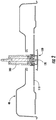
- FIG. 2 illustrates a cross section view taken through a center of the cutting deck 40.
- shaft 100 (often also referred to as a spindle) may extend downward into a center region of the cutting deck 40.
- a blade 110 may be attached to the shaft 100.
- the blade 110 may be directly attached to the shaft 100 via an attachment device such as, for example, bolt 120.
- the bolt 120 may pass through an opening in a center of the blade 110 and thereafter be screwed into a distal end of the shaft 100 (e.g., with or without a washer between the bolt 120 and the blade 110).
- blade removal would require the bolt 120 to be removed. This, of course would require the use of tools, and may require tipping, removal or elevation of the cutting deck 40.
- Some example embodiments may provide for the inclusion of a mounting apparatus (e.g., blade mount 130), which may enable the blade 110 to be removed without tools and, in some cases, without requiring tipping, removal or elevation of the cutting deck 40.
- the blade mount 130 may be operably coupled to the shaft 100.
- the blade mount 130 may be directly affixed to the shaft 100 via the bolt 120.
- the bolt 120 may pass through an opening in a center portion of the blade mount 130 (e.g., with or without a washer between the bolt 120 and the blade 110) and may be tightened to affix the blade mount 130 to the shaft 100.
- FIG. 3 which includes FIGS. 3A and 3B , shows isolated views of components associated with the blade mount 130 according to an example embodiment.
- FIG. 3A illustrates a side view looking down the longitudinal length of the blade 110
- FIG. 3B illustrates a side view from a position perpendicular to the longitudinal length of the blade 110.
- FIG. 3 illustrates a portion of the shaft 100 passing into a housing 140 that may protect the shaft 100 from debris that may impact the rotatability of the shaft 100.
- the shaft 100 may terminate at a mounting plate 150 to which the blade mount 130 may be attached, or against which the blade mount 130 may be drawn by tightening of the bolt 120 to the shaft 100.
- the blade mount 130 may include a covering that may be provided to shield the blade mount 130 from debris during operation.
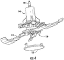
- FIG. 4 illustrates a perspective view of components associated with the blade mount 130 employing a covering according to an example embodiment.
- FIG. 4 shows a blade mount cover 132 removed from the blade mount 130.
- the blade mount cover 132 may be a plate shaped piece of metal, plastic or other rigid material that may be affixed (e.g., via a snap assembly) over the blade mount 130.
- the blade mount cover 132 may be optional, and thus some embodiments may not include the blade mount cover 132.
- the blade mount 130 of an example embodiment may include a spring clamp design.
- FIG. 5 illustrates an example embodiment of the blade mount 130 showing the spring clamp design where the blade mount 130 is released and the blade 110 is removed.
- FIG. 6 which includes FIGS. 6A , 6B and 6C , illustrates a top view of the blade 110 of an example embodiment.
- FIG. 6A illustrates a top view of the blade 110.
- FIG. 6B illustrates a top perspective view of a version of the blade 110 that may be used in connection with a blade mount employing a stamped blade mount base (e.g., like the one shown in FIG. 7B ).
- FIG. 5 illustrates an example embodiment of the blade mount 130 showing the spring clamp design where the blade mount 130 is released and the blade 110 is removed.
- FIG. 6 which includes FIGS. 6A , 6B and 6C , illustrates a top view of the blade 110 of an example embodiment.
- FIG. 6A illustrates a top view of the blade 110.
- FIG. 6B illustrate
- FIG. 6C illustrates a top perspective view of a version of the blade 110 that may be used in connection with a blade mount employing a cast blade mount base (e.g., like the one shown in FIG. 7A ).
- the blade 110 may include alignment slots 160 and a bolt receiver 170.
- the bolt receiver 170 may be a cutout portion disposed at a center of the blade 110 (e.g., centered around an intersection of the longitudinal and transverse centerlines of the blade 110) to allow the blade 110 to fit within the blade mount 130 without having interference from the bolt 120.
- the bolt receiver 170 may pass from a top face of the blade 110 to a bottom face of the blade 110 at the axis of rotation of the blade 110 to define a gap through which the bolt 120 may pass to enable the blade 110 to fist snugly within the blade mount 130 even though the bolt 120 may also protrude into the blade mount 130.
- there may be no force exerted by the bolt 120 on the blade 110 and in some cases there may be no contact between the bolt 120 and the blade 110 due to the bolt 120 fitting within the bolt receiver 170.
- the alignment slots 160 and the bolt receiver 170 may be employed for attachment of the blade 110 to the blade mount 130 as described below.
- the alignment slots 160 may form a cutout portion of the blade 110 passing from one of the top face or bottom face toward the other of the top face or the bottom face.
- the at least one alignment slot may disposed spaced apart from an axis of rotation of the blade to receive a corresponding protruding member of a blade mount configured to hold the blade at a portion of the blade other than at the axis of rotation during rotation of the blade responsive to operation of the lawn mower.
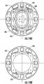
- the blade mount 130 may include a blade mount base 200 that may form a portion of the blade mount 130 to which a clamping device or component (e.g., a spring clamp) is attached.
- FIG. 7 which includes FIGS.
- FIG. 7A and 7B illustrates a detailed view of two alternative example embodiments of the blade mount base.
- FIG. 7A illustrates an example embodiment in which the blade mount base 200 is cast as a single unitary piece
- FIG. 7B illustrates an example embodiment in which blade mount base 200' is stamped from a single unitary piece of metal.
- the blade mount 130 of this example embodiment may include the blade mount base 200 which may be rotatably attached to a clamp 240 via pivot pins 212 (or a single pivot pin) that may fit within pivot pin receivers 202 disposed at a portion of the blade mount base 200.
- the blade mount base 200 may further include an attachment orifice 220 that may be disposed at a center portion of the blade mount base 200.
- the attachment orifice 220 is shown to have a star pattern in order to receive a correspondingly patterned protrusion that may extend beyond the surface of the mounting plate 150.
- any circular or non-circular pattern could be employed on the mounting plate 150 and the attachment orifice 220.
- the bolt 120 may pass through the attachment orifice 220 to engage the shaft 100 to secure the blade mount base 200 to the mounting plate 150 responsive to tightening of the bolt 120.
- a washer 121 or other intermediate plate shaped component may be disposed between the bolt 120 and the surface of the blade mount base 200 surrounding the attachment orifice 220.
- the pivot pin receivers 202 may be disposed in guide posts 230 that may form one edge of a blade reception channel 232 at a surface of the blade mount base 200.
- a locking post 234 may be disposed at an opposite side of the blade reception channel 232 relative to each respective one of the guide posts 230.
- the blade reception channel 232 may include alignment protrusions 236 that may be disposed on opposite sides of the attachment orifice 220. In some embodiments, the alignment protrusions 236 may protrude into the blade reception channel 232 from the blade mount base 200 to project into the alignment slots 160 of the blade 110.
- the alignment protrusions 236 and the alignment slots 160 may be offset to opposite sides relative to a centerline of the longitudinal length of the blade 110.
- the alignment protrusions 236 may have a height that is approximately equal to the thickness of the blade 110 so that the tops of the alignment protrusions are flush with the surface of the blade 110 when the blade 110 is properly positioned in the blade reception channel 232.
- the blade mount base 200 may further include cover snap receivers 238 configured to receive snap fittings associated with the blade mount cover 132 (if employed).
- the blade mount base 200 includes two snap receivers 238, one on each side of the blade reception channel 232 and located far enough from the blade reception channel so that clamp 240 does not interfere with the latch snap fittings on the blade mount cover 132.
- the clamp 240 may be operably coupled to the blade mount base 200 via the pivot pins 212.
- the clamp 240 may be rotatable with the pivot pins forming the axis of rotation and may be lockable via engagement of a latch assembly 250 onto the locking posts 234.
- the latch assembly 250 may include a latch cover 252 that rotates about a roll pin 254 to enable engagement and/or disengagement of a wire element 256 that may be rotatably attached to the latch cover 252 at a portion of the latch cover 252 that is offset from a position at which the roll pin 254 engages the latch cover 252.
- the wire element 256 may be bent as it extends from the point of engagement of the wire element 256 to the latch cover 252 to a crossbar portion of the wire element 256 that engages the locking posts 234.
- the bend in the wire element 256 may enable the wire element 256 to provide a spring-like force to pull the latch cover 252 down toward the clamp 240 when the latch cover 252 is rotated about the roll pin 254 while the wire element 256 engages the locking posts 234.
- FIG. 8 illustrates a side view of the blade mount 130 in the clamped position according to an example embodiment.
- FIG. 8 illustrates a side view of the blade mount 130 in the clamped position according to an example embodiment.
- the point 258 which rotates in a circular motion about the center of the roll pin 254, must move further away from the point 257 until it passes through the plane.
- the bend in the wire element 256 permits the point 258 to move further away from point 257 to some extent, but only when the spring force is overcome by, for example, the force exerted by the hand of an operator trying to unlock the latch cover 252. In this way, the latch cover 252 is held in the latched position and the clamp 240 is locked into the clamped position shown in FIG. 8 .
- the point 257 is slightly higher than the center of the roll pin 254 (when viewed from the perspective of FIG. 8 ).
- the clamp 240 may be configured to rotate about the pivot pins 212 to a position proximate to the blade reception channel 232 to lock or clamp the blade 110 into place (e.g., between the clamp 240 and the blade mount base 200) responsive to the latch assembly 250 engaging and clamping onto the locking posts 234.
- a plane in which the blade 110 lies may be substantially parallel to a plane in which the clamp 240 lies and a plane in which the latch cover 252 lies when the wire element 256 is clamped to the locking posts 234.
- the latch cover 252 may be further secured in a clamped position in some embodiments.
- a locking assembly 260 may be provided to enable the latch cover 252 to be further secured in the clamped position.
- the locking assembly 260 may include a locking protrusion 262 that may extend through a lock receiver 264 attached to or otherwise forming a portion of the latch cover 252.
- a pin (not shown), such as a cotter pin, R-clip, hairpin or other pin, may extend through the locking protrusion 262 to engage the latch cover 252 responsive to insertion of the locking protrusion 262 through the lock receiver 264.
- the locking protrusion 262 may include a rotatable catch 266 disposed at a distal end thereof.
- the rotatable catch 266 may have a slanted head to allow the lock receiver 264 (e.g., an aperture in the latch cover 252 shaped to receive the rotatable catch 266 and the distal end of the locking protrusion 262 there-through) to slide easily over the rotatable catch 266 by rotating the head of the rotatable catch 266 when moving the latch cover 252 to the clamped position.
- the rotatable catch 266 may be biased (e.g., by a helical torsion spring or other spring located proximate the axis of a hinge-type connection between the rotatable catch 266 and the locking protrusion 262) to rotate to a position at which the rotatable catch 266 prevents movement of the latch cover 252 out of the clamped position.
- the operator may simply rotate the rotatable catch 266 to enable the lock receiver 264 to clear the rotatable catch 266 and then rotate the latch cover 252 in the opposite direction to move it out of the clamped position.
- the lock receiver 264, rotatable catch 266, and locking protrusion 262 are located near the end of the latch cover 252 opposite the roll pin 254 so that the operator may be able to rotate the rotatable catch 266 and lift the latch cover 252 out of the clamped position all with one hand.
- FIG. 8 shows the latch cover 252 rotated to engage the wire element 254 with the locking posts 234.
- the rotatable catch 266 is also shown having cleared the latch cover 252 to prevent inadvertent unlatching of the blade mount 130.
- FIG. 8 also clearly shows the blade reception channel 232 formed between the blade mount base 200 and the clamp 240. The offset arrangement of the alignment protrusions 236 within the blade reception channel 232 is also visible.
- the blade mount base 200 may further include magnet receptacles 270.
- the magnet receptacles 270 may include magnets (not shown), such as neodymium magnets or other permanent magnets. These magnets may hold the metal blade 110 to the blade mount base 200 when the blade 110 is installed in the blade reception channel 232. Accordingly, for example, the operator may be enabled to reach under the cutting deck 40 with one hand and operate the latch cover 252 to push the rotatable catch 266 to allow the latch cover 252 to be rotated to release the wire element 254 from the locking posts 234.
- the magnets in the magnet receptacles 260 may hold the blade 110 proximate to the blade mount base 200 to prevent the blade 110 from simply falling out of the blade mount 130.
- the operator may overcome the magnets and remove the blade 110 to sharpen or replace the blade 110. Meanwhile, when the blade 110 (either sharpened or replaced) is to be put back into the blade mount 130, the magnets may hold the blade 110 in place while the operator manipulates the latch assembly 250 to the clamped position.
- the operator may be enabled to remove and/or replace the blade 110 with one hand, and without tools.
- lawn mowers e.g., the riding lawn care vehicle
- cutting assemblies may be manufactured with embodiments of the blade mount 130 equipped thereon.
- Such devices may be equipped to enable quick-change blades to be employed directly out of the factory.
- the blade mount 130 may be mounted in the same manner in which a blade would otherwise be mounted.
- the blade mount base 200 may mount to the lawn mower in similar fashion to the manner in which a blade in normally mounted.
- a quick-change blade e.g., blade 110
- the lawn mower may thereafter be considered to be retrofitted to handle quick-change blades.
- the stamped version of the blade mount base 200' also includes an attachment orifice 220' disposed substantially at a midpoint of a longitudinal centerline of the blade mount base 200'.
- the blade mount base 200' also includes pivot pin receivers 202' disposed in guide posts 230' that may form one edge of a blade reception channel 232' at a surface of the blade mount base 200'.
- a locking post 234' may be disposed at an opposite side of the blade reception channel 232' relative to each respective one of the guide posts 230'.
- the blade reception channel 232' may include alignment protrusions 236' that may be disposed on opposite sides of the attachment orifice 220'.
- the alignment protrusions 236' may protrude into the blade reception channel 232' from the blade mount base 200' to project into the alignment slots 160 of the blade 110. To ensure that the blade 110 cannot be installed incorrectly, the alignment protrusions 236' and the alignment slots 160 may be offset to opposite sides relative to a centerline of the longitudinal length of the blade 110. In an example embodiment, the alignment protrusions 236' may have a height that is approximately equal to the thickness of the blade 110 so that the tops of the alignment protrusions are flush with the surface of the blade 110 when the blade 110 is properly positioned in the blade reception channel 232'. In some cases, the blade mount base 200' may further include cover snap receivers 238' configured to receive snap fittings associated with the blade mount cover 132 (if employed). The blade mount base 200' may further include magnet receivers 270' as described above.
- the alignment protrusions 236 or 236' are disposed substantially equidistant from opposing sides of the longitudinal centerline of the blade mount base 200 or 200'. However, each of the alignment protrusions 236 or 236' are disposed to be offset relative to the transverse centerline of the blade mount base 200 or 200'.
- At least a majority portion of one of the alignment protrusions 236 or 236' is disposed on a first side of the transverse centerline of the blade mount base 200 or 200', while at least a majority portion of the other of the alignment protrusions 236 or 236' is disposed on a second side of the transverse centerline of the blade mount base 200 or 200' (the first and second sides being opposite sides of the transverse centerline).
- the alignment slots 160 of the blade 110 are correspondingly formed to enable the blade 110 of some example embodiments to be held in place (at least in a direction substantially perpendicular to the axis of rotation of the blade 110 during operation) exclusively by the engagement between the alignment slots 160 and the alignment protrusions 236 or 236'.
- the clamp 240 may assist in holding the blade 110 in place along the axis of rotation of the blade 110.
- the alignment slots 160 are disposed substantially equidistant from opposing sides of the transverse centerline of the blade 110 (on opposite sides of the bolt receiver 170).
- each of the alignment slots 160 are disposed to be offset relative to the longitudinal centerline of the blade 110.
- At least a majority portion of one of the alignment slots 160 is disposed on a first side of the longitudinal centerline of the blade 110, while at least a majority portion of the other of the alignment slots 160 is disposed on a second side of the longitudinal centerline of the blade 110 (the first and second sides being opposite sides of the longitudinal centerline).
- the bolt receiver 170 is merely provided to enable the bolt 120 (or a nut attached to the bolt) to affix the blade mount 130 to the shaft 100, but the bolt receiver 170 itself does not engage, hold or facilitate holding of the blade 110 in place, the blade 110 is propelled exclusively via the engagement between the alignment slots 160 and the alignment protrusions 236 or 236'.
- FIGS. 2-8 illustrate one example embodiment of a blade mount capable of supporting quick change blades
- a blade mount capable of supporting quick change blades
- other shapes and constructions of quick-change blades may be supported.
- quick-change blades may be single unitary components that are attachable to a blade mount in one piece.
- the blade mount may be configured to grasp the quick change blade at a center portion of the quick change blade.
- quick change blades may include separate blade sections that attach to the blade mount.
- FIGS. 9-20 show various examples of quick-change blade arrangements that may be possible according to some alternative example embodiments.
- a blade mount 300 may be provided that provides for attachment of a quick-change blade to the shaft via a different clamping mechanism than that which is shown in FIGS. 2-8 .
- FIGS. 9-14 illustrate examples of another embodiment employing a quick-change blade system.
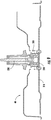
- FIG. 9 illustrates a cross section of the cutting deck 40 in which a different clamping mechanism is employed.
- FIG. 10 illustrates a perspective view of a quick change blade 310 according to this example embodiment.
- FIG. 11 which includes FIGS. 11A and 11B , illustrates side views of the blade mount 300 of this example embodiment seen looking down the longitudinal length of the blade 310 ( FIG.
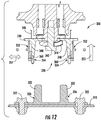
- FIG. 12 illustrates a cross section view of the blade mount 300 and corresponding portions of the blade 310 with the blade 310 removed
- FIG. 13 shows roughly the same portions shown in FIG. 12 , with the blade 310 affixed to the blade mount 300.
- FIG. 14 which includes FIGS. 14A and 14B , illustrates a cross section view of the blade mount 300 taken through horizontal channels 353 disposed in a blade release assembly 352 of the blade mount 300.
- FIG. 14A is a cross section view looking down into the recess 330 at a level of the horizontal channels 353
- FIG. 14B is a cross section view looking in the opposite direction at a level of the horizontal channels 353.
- blade mount 300 employs a retractable set of locking pins within a releasable pin holding assembly to engage a shaped protrusion 320 that may be attached to or otherwise form a portion of the blade 310.
- FIG. 10 illustrates the shaped protrusion 320 in more detail. As can be seen in FIG. 10 , the shaped protrusion 320 may be attached to a center portion of the blade 310. The attachment between the blade 310 and the shaped protrusion may be accomplished via connection bolts 322, as shown in FIG. 10 , or via any other suitable method (e.g., welding, adhesives, rivets, and/or the like).
- the shaped protrusion 320 may extend substantially perpendicularly away from a surface of the blade 310 to form a shape configured to fit within a correspondingly shaped recess 330 in the blade mount 300.
- the shape in FIG. 10 is substantially oval shaped.
- any suitable shape may be utilized including rectangular, square, hexagonal, star shaped, or various other shapes that may be regular or irregular. Even a round shape may be employed in some cases, such as when detents or other irregularities are provided on the round shape to prevent free rotation of the shaped protrusion 320 within the corresponding recess 330 in the blade mount 300.
- the shaped protrusion 320 may be formed to taper slightly along its length extending away from the surface of the blade 310.
- the tapered shape may be matched by the recess 330 and may provide for an easier opportunity to fit the tapered end of the shaped protrusion 320 into the wider opening of the recess 330, while enabling the fit to become more snug until full seating of the shaped protrusion 320 in the recess 330 when the blade 310 is clamped within the blade mount 300.
- the shaped protrusion 320 When fully seated, the shaped protrusion 320 may have a substantially tight fit with the recess 330.
- the shaped protrusion 320 may include pin reception slots 326 disposed on opposite sides of the shaped protrusion 320.
- the pin reception slots 326 may be disposed at opposite sides of the shaped protrusion 320 along the longitudinal centerline of the blade 310 oriented to be substantially perpendicular to the longitudinal centerline of the blade 310.
- the pin reception slots 326 may mate with retractable pins associated with the blade mount 300 as described in greater detail below.
- the blade mount 300 may include a blade mount base 340 that may be affixed (e.g., via bolt 342 and in some cases also a washer 344) to a shaft 350 that may be coupled to the engine 50 as described above.
- the bolt 342 may pass through an orifice in the center portion of the blade mount base 340 to engage the shaft 350.
- the blade mount base 340 may be shaped to fit a pattern (e.g., the star pattern shown in FIG. 7 ) disposed on a mounting plate 346 to which the blade mount base 340 attaches.
- the blade mount base 340 may include sidewalls 348 that extend perpendicularly away from the mounting plate 346 when the blade mount base 340 is affixed to the mounting plate 346 (e.g., via tightening of the bolt 342) to form the recess 330.
- a blade release assembly 352 may be operably coupled to the blade mount base 340.
- the blade release assembly 352 may extend around the circumference of the sidewalls 348 and may slidably engage the sidewalls 348.
- internal springs (not shown) may bias the blade release assembly 352 to be pushed away from the mounting plate 346 when the blade mount base 340 is attached to the mounting plate 346.
- the blade release assembly 352 When the operator pushes against the springs with sufficient force to overcome the spring force, the blade release assembly 352 may slide up the sidewalls 348 toward the mounting plate 346 in a direction indicated by arrow 355 of FIG. 12 . However, when no force is applied to overcome the spring force, the blade release assembly 352 may be pushed in a direction opposite of the direction indicated by arrow 355 by the springs.
- the sidewalls 348 may include a slanted pin channel 354 on each opposing side of the recess 330.
- the slanted pin channels 354 may be disposed such that one of the slanted pin channels 354 is positioned to correspond to each respective one of the pin reception slots 326 when the shaped protrusion 320 is inserted into the orifice 330.
- the slanted pin channel 354 of one example embodiment lies perpendicular to a longitudinal centerline of the blade 310 when the blade 310 is installed in the blade mount 300, such orientation is not required in all embodiments.
- a retractable pin 360 may be disposed in each of the slanted pin channels 354 and may be enabled to move freely within the slanted pin channel 354 and extend out of at least a portion of the slanted pin channel 354 and into the recess 330 when the blade release assembly 352 is in its rest position disposed farthest away from the mounting plate 346 responsive to urging from the internal springs. However, when the blade release assembly 352 is forced upward or toward the mounting plate 346 to overcome the internal springs, the retractable pin 360 may be withdrawn into the slanted pin channel 354 and out of the recess 330 as the retractable pin 360 rides along the slanted pin channel 354 in an upward direction to follow the movement of the blade release assembly 352.
- the blade release assembly 352 may include a horizontal pin channel 353 that is oriented substantially parallel to the arrow 357.
- the retractable pin 360 may be disposed within the horizontal pin channel 353 and may be biased (e.g., via one or more springs) toward the recess 330 on each respective side.
- the retractable pin 360 may be pushed by biasing springs within the horizontal pin channel 353 toward the recess 330.
- the retractable pin 360 may be at least partially disposed within the orifice and may be capable of engaging its corresponding pin reception slot 326 to clamp the blade 310 to the blade mount 300. However, as the blade release assembly 352 is forced out of the rest position, the blade release assembly 352 may move upwardly (e.g., in the direction of arrow 355). Given that the retractable pin 360 is fixed in its vertical position relative to the blade release assembly 352 by virtue of its disposal within the horizontal pin channel 353, the retractable pin 360 may engage the slanted surface of the slanted pin channel 354 to ride within the slanted pin channel 354 upwardly, while being drawn away from the orifice 330 within its respective horizontal pin channel 353.
- contact with a surface of the slanted pin channel 354 may draw the retractable pin 360 away from the orifice 330 within the horizontal pin channel 353 to overcome the biasing springs and move the retractable pin 360 upwardly through the slanted pin channel 354.
- a portion of the pin reception slot 326 may be slanted to match the gradient of the slanted surface of the slanted pin channel 354 to permit a smooth transition of the retractable pin 360 from having portions thereof in contact with the pin reception slot 326 (which is disposed in the orifice 330), to having all portions thereof in contact with the slanted pin channel 354.
- the blade 310 When the retractable pin 360 is pushed into the orifice 330 region to engage the pin reception slot 326, the blade 310 may be affixed to the blade mount 300. More specifically, the shaped protrusion 320 may be held proximate to the sidewalls 348 of the blade mount 300.
- FIG. 12 illustrates a released blade 310, responsive to movement of the blade release assembly 352 toward the mounting plate 346.
- the sharpened or replaced blade may then be affixed to the blade mount by simply aligning the shaped protrusion 320 with the orifice and pushing the sharpened or replaced blade upwardly until the retractable pin 360 engages the pin reception slot 326 to clamp the sharpened or replaced blade to the blade mount 300.
- FIG. 13 shows the blade 310 clamped to the blade mount 300 with the blade release assembly 352 in its rest position.
- FIGS. 2-14 each support a single blade.
- a single blade that includes cutting surfaces at opposite ends thereof is held in place by a blade mount that engages the blade at a center portion of the blade.
- some embodiments may employ a blade mount that engages two (or more) separate blade portions.
- separate cutting surfaces associated with corresponding separate blade portions may be supported from some example blade mounts associated with example embodiments of the present invention.
- FIGS. 15-18 illustrate examples of such embodiments.
- FIG. 15 illustrates a perspective view of a blade mount 400 of an example embodiment.
- the blade mount 400 of FIG. 15 includes one portion thereof with a blade engagement assembly 405 affixed thereto, and another portion with the blade engagement assembly 405 removed to facilitate explanation of the operation of an example embodiment.
- FIG. 16 illustrates a perspective view of a quick-change blade 410 according to an example embodiment.
- FIG. 17 illustrates a perspective view of the blade 410 attached to the blade mount 400 by being clamped within the blade engagement assembly 405.
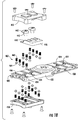
- FIG. 18 illustrates an exploded view of components of the blade engagement assembly 405 according to an example embodiment.
- the blade mount 400 may include a blade mount base 420 that may include a mounting receiver 422 disposed at a center portion thereof.
- the mounting receiver 422 may be affixed to a rotatable shaft of the lawn mower (e.g., riding lawn care vehicle 10) as described above.
- the mounting receiver 422 may be an orifice shaped to match an engagement shape positioned on a mounting plate corresponding to a mandrel or other mounting surface to which the mounting receiver 422 may be affixed.
- a bolt may be passed through the mounting receiver 422 to engage the shaft and affix the blade mount 400 to the mounting plate.
- a washer may be inserted between the bolt and the mounting receiver 422 to increase the contact area and holding force on the blade mount 400 to affix the blade mount 400 to the mounting plate of the lawn mower.
- the blade mount base 420 may include a blade insertion slot 430 at each respective end of the blade mount base 420.
- Each blade insertion slot 430 may be configured to receive an example embodiment of the blade 410.
- each blade insertion slot 430 provides an opening for insertion of the blade 410 into a corresponding blade engagement assembly 405 to be held within the blade insertion slot 430.
- the blade insertion slot 430 represents a gap that extends substantially parallel to the top and bottom surfaces of the blade mount base 420.
- the blade insertion slot 430 may extend at least from a distal end of the blade mount base 420 inwardly toward the mounting receiver 422.
- the blade insertion slot 430 also extends along one side of the blade mount base 420 from the distal end of the blade mount base 420 to a position proximate to the location of the mounting receiver 422 to enable side entry of the blade 410 into the blade insertion slot 430 and into the blade engagement assembly 405.
- both side portions may be closed and the blade insertion slot 430 may extend over only the distal end of the blade mount base 420.
- the blade 410 would be inserted directly inline with a longitudinal centerline of the blade mount 400.
- the blade 410 may be inserted from a side substantially perpendicular to the longitudinal centerline of the blade mount 400. More specifically, in the pictured example, blades may be entered into opposite sides of the blade mount 400 since the blade insertion slots 430 may extend over opposite sides of the blade mount body 420.
- the blade 410 may include a blade body 412 that may take the form of an elongate plate shaped member. However, the blade body 412 may include one or more bends, curves or other shaping features to improve aerodynamic characteristics, cutting performance or other desirable characteristics.
- the blade body 412 may extend along its longitudinal centerline from a cutting end 414 to an attachment end 416.
- the cutting end 414 may include a leading edge portion that may be sharpened to cut vegetation as the blade 410 is rotated and a trailing edge portion that may be sloped or otherwise shaped for aerodynamic performance reasons.
- the cutting end 414 may form a distal end of the blade 410 relative to the blade mount 400 when the blade 410 is inserted into the blade mount 400 and the attachment end 416 may form a proximal end thereof since the attachment end 416 may be inserted into the blade insertion slot 430.
- the blade 410 may include one or more detent receivers 418 disposed proximate to the attachment end 416.
- the detent receivers 418 may receive one or more detents that may be retractably inserted into the detent receivers 418 to affix the blade 410 to the blade engagement assembly 405 or otherwise hold the blade 410 in place within the blade insertion slot 430.
- the detent receivers 418 are round, and two are placed spaced apart along a longitudinal centerline of the blade 410. However, the detent receivers 418 could have other shapes, and other positions in alternative embodiments.
- the blade mount base 420 may include receiving orifices 424.
- the receiving orifices 424 of this example embodiment may be disposed along the longitudinal centerline of the blade mount base 420 at positions that correspond to the positions of the detent receivers 418 when the blade 410 is inserted into the blade insertion slot 430. As such, when the blade 410 is inserted into the blade insertion slot 430, the receiving orifices 424 may substantially align with the detent receivers 418.
- retractable detents 440 of FIG. 18 may pass through both the receiving orifices 424 and the detent receivers 418.
- the retractable detents 440 may be disposed within a blade engagement assembly housing 450 of the blade engagement assembly 405 at locations that correspond to the receiving orifices 424.
- the retractable detents 440 may be spring loaded to be biased to be inserted through the receiving orifices 424 and, if the blade 410 is in the blade insertion slot 430, through the detent receivers 418.
- the retractable detents 440 may include slide engaging surfaces 442 that may be configured to engage sliding surfaces 444 disposed on an unlocking tab 446.
- the unlocking tab 446 of this example may be disposed at a side portion of the blade engagement assembly housing 450 and may extend out of a gap between a portion of the blade engagement assembly housing 450 and the blade mount base 420. As such, a portion of the unlocking tab 446 may slide along a surface of the blade mount base 420 responsive to an operator pressing on the unlocking tab 446. When the unlocking tab 446 slides over the blade mount base 420 further into the blade engagement assembly housing 450, the sliding surfaces 444 may engage the side engaging surfaces 442 and lift the retractable detents 440 out of the detent receivers 418. The blade 410 may then be unclamped and removable from the blade mount 400.
- the retractable detents 440 may include slanted surfaces at distal ends thereof and the slanted surfaces may be oriented toward a direction from which entry of the blade 410 into the blade insertion slot 430 is expected. As such, when the blade 410 is inserted into the blade insertion slot 430, the blade 410 may engage the slanted surfaces and enable the retractable detents 440 to ride upward and out of the way of the blade 410 until the blade 410 is inserted to a point at which the detent receivers 418 are substantially aligned with the receiving orifices 424, at which time the retractable detents may be inserted through the detent receivers 418 to hold the blade 410 in place within the blade insertion slot 430.
- the blade insertion slot 430 may be formed to have a width that is slightly wider than the width of the blade 410.
- the blade engagement assembly housing 450 may be provided with one or more sets of spring loaded rollers 460 that may enable different blade widths to be accounted for by consuming any gaps between the blade 410 and interior walls defining the blade insertion slot 430.
- the spring loaded rollers 460 may include springs 462 that engage the blade engagement assembly housing 450 at one end thereof, and engage a roller ball 464 at the other end thereof.
- the rollers 460 may extend through roller receivers 466 disposed in the blade mount base that extend into the blade insertion slot 430.
- the roller receivers 466 may be arrayed in any desirable arrangement and may be included on the top and bottom of the blade mount base 420 or just on one of the top or bottom of the blade mount base 420. As the blade 410 is inserted into the blade insertion slot 430, the rollers 460 may be urged into contact with the blade 410 to assist in providing a secure fit between the blade 410 and the blade mount 400. When the retractable detents 440 engage the receiving orifices 424, the blade 410 may be held securely within the blade mount 400.
- the operator may slide the blade 410 out of engagement with the rollers 460 and out of the blade insertion slot 430 to enable the operator to sharpen or replace the blade 410.
- the blade mount 400 may be modified to support additional blades beyond just two. Although a blade mount could simply be provided with additional body portions extending to provide additional blade insertion slots, in some cases, multiple blade mounts could be stacked on each other in an offset fashion, for example, to provide mulching capabilities.
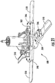
- FIGS. 19-21 illustrate one such example embodiment.
- FIG. 19 illustrates a top view of a blade mount 500 according to another example embodiment.
- FIG. 20 illustrates a perspective view of the blade mount 500 with quick-change blades 510 removed.
- FIG. 21 illustrates a perspective view of the blade mount with the blades 510 installed.
- the blades 510 may be similar to the blades 410 shown in FIGS. 15-18 except that in this example the blades 510 only include a single detent receiver 518 since the blade mount 500 employs a blade insertion slot 530 that extends only across the distal end of the blade mount 500.
- the blade mount 500 also operates similar to the blade mount 400 except that unlocking tab 546, which is depressed to release a locked blade, may be disposed at the distal end of the blade mount 500 instead of on the side of the blade mount 400 of FIGS. 15-18 . As shown in FIGS.
- the blade mount 500 may include two vertically offset blade mount components (e.g., upper blade mount component 502 and lower blade mount component 504) so that the blades 510 associated with the upper blade mount component 502 may be at a different elevation than blades associated with the lower blade mount component 504. This configuration may assist with providing a mulching action as the blades are rotated by a lawn mower.
- example embodiments provide various different ways that a quick-change blade system may be employed to provide operators with a mechanism by which blades may be removed or replaced relatively easily and quickly. Moreover, some example embodiments may enable blade removal and/or replacement to be performed without tools and, in at least some cases with one hand. Some embodiments may enable blade change/replacement to be performed without tipping the lawn mower, elevating the lawn mower or removing the cutting deck. Thus, operators may enjoy a simpler blade change/removal procedure and may be encouraged to perform blade sharpening or replacement on a more frequent basis to keep lawn care performance and quality at a high level.
- a blade mount is provided that may be operably coupled to a rotatable shaft.
- the blade mount may include at least one engagement slot (e.g., blade insertion slot 430/530) enclosing at least a portion of at least one blade.
- the blade mount may further include at least one protruding member (e.g., retractable detents 440) disposable within the engagement slot to secure the at least one blade within the engagement slot responsive to insertion of the at least one blade into the engagement slot.
- the blade mount may include an orifice configured to releasably receive a shaped protrusion operably coupled to at least one blade.
- the blade mount may include a blade release assembly configured to facilitate holding the shaped protrusion within the orifice in a first position of the blade release assembly and to release the shaped protrusion responsive to movement of the blade release assembly to a second position.
- the blade mount may include a latch assembly configured to rotate a clasp relative to a blade reception channel to engage at least a portion of the at least one blade.
- a lawn care device may include a cutting deck housing at least one blade, a rotatable shaft, and a blade mount operably coupled to the rotatable shaft.
- the blade mount may include at least one engagement slot configured to enclose at least a portion of the at least one blade.
- the blade mount may further include at least one protruding member disposed within the engagement slot to secure the at least one blade within the engagement slot responsive to insertion of the at least one blade into the engagement slot.
- the lawn care device of some embodiments may include additional features that may be optionally added.
- the engagement slot may be defined by a latch assembly.
- the engagement slot may be formed between a blade mount base and a rotatable clasp of the latch assembly.
- the at least one protruding member may be provided at the blade mount base to include a first protruding member and a second protruding member, where the first and second protruding members are disposed substantially equidistant from respective opposing sides of a longitudinal centerline of the blade mount base.
- the first and second protruding members may be disposed to be offset relative to the transverse centerline of the blade mount base.
- At least a majority portion of the first protruding member may be disposed on a first side of the transverse centerline of the blade mount base and at least a majority portion of the second protruding member is disposed on a second side of the transverse centerline of the blade mount base.
- the blade mount base may engage one face of the blade and the clasp may engage an opposite face of the blade responsive to the blade being held by the blade mount.
- the clasp may further include a locking assembly and a latch cover, where the locking assembly enables the latch cover to be secured to hold the clasp proximate to the blade.
- any or all of (1) to (4) may be employed, and the blade mount base may include a set of guide posts and a set of locking posts disposed on opposing sides of the engagement slot, where the clasp further comprises a locking assembly and a latch cover, and the locking assembly enables the latch cover to be secured to hold the clasp proximate to the blade via engagement of a wire element with the set of locking posts.
- any or all of (1) to (4) may be employed, and the blade mount base may include a set of guide posts and a set of locking posts disposed on opposing sides of the engagement slot, where the clasp further comprises a locking assembly and a latch cover, the locking assembly enables the latch cover to be secured to hold the clasp proximate to the blade via engagement of a wire element with the set of locking posts, the wire element is rotatably coupled with the clasp to provide a spring force to pull the latch cover down toward the clamp when the latch cover is rotated such that a substantial portion of the latch cover lies in a plane substantially perpendicular to a plane in which the clasp lies while the wire element engages the set of locking posts.
- any or all of (1) to (4) may be employed, and the clasp may further include a locking assembly and a latch cover, the locking assembly enabling the latch cover to be secured to hold the clasp proximate to the blade, wherein the locking assembly comprises a locking protrusion configured to extend through a lock receiver attached to or otherwise forming a portion of the latch cover, and wherein the locking protrusion comprises a rotatable catch disposed at a distal end thereof.
- the blade mount may include a non-circular shaped aperture configured to receive a correspondingly shaped protrusion therein to couple the blade mount to the rotatable shaft.
- the non-circular shaped aperture may include a star-shaped hole.
- the engagement slot may include a non-circular and tapered cavity configured to receive a correspondingly shaped protrusion that may be attached to or otherwise form a portion of the blade, and the at least one protruding member may be disposed within the engagement slot of the blade mount which may include a retractable set of locking pins within a releasable pin holding assembly and may be configured to engage apertures in the shaped protrusion attached to or otherwise forming a portion of the blade.
- the engagement slot may include a plurality of spring-loaded rollers configured to allow a portion of a blade to be slid into the engagement slot
- the at least one protruding member may include at least one retractable detent
- the blade mount may further include an unlocking tab that, when actuated, is configured to remove the at least one retractable detent from engagement with at least one receiving orifice in a blade disposed in the engagement slot.
- a blade mount may be provided.
- the blade mount may be configured to couple a blade to a rotatable shaft.
- the blade mount may include at least one engagement slot configured to enclose at least a portion of the blade, and at least one protruding member disposed within the engagement slot to secure the blade within the engagement slot responsive to insertion of the blade into the engagement slot.
- the blade mount may be provided with the features and combinations of features described above.
- a cutting blade for a lawn mower may include a top face, a bottom face, and at least one alignment slot forming a cutout portion of the blade passing from one of the top face or bottom face toward the other of the top face or the bottom face.
- the at least one alignment slot may be disposed spaced apart from an axis of rotation of the blade to receive a corresponding protruding member of a blade mount configured to hold the blade, via engagement of the protruding member with the at least one alignment slot, at a portion of the blade other than at the axis of rotation during rotation of the blade responsive to operation of the lawn mower.
- the at least one alignment slot may include a first alignment slot disposed spaced apart from the axis of rotation of the blade to receive a corresponding first protruding member of the blade mount, and a second alignment slot disposed spaced apart from the axis of rotation of the blade to receive a corresponding second protruding member of the blade mount.
- the first and second alignment slots may be disposed on substantially opposite sides of the axis of rotation.
- the first and second alignment slots may each be disposed substantially equidistant from opposing sides of a transverse centerline of the blade.
- the first and second alignment slots may each be disposed to be offset relative to a longitudinal centerline of the blade.
- At least a majority portion of the first alignment slots may be disposed on a first side of the longitudinal centerline of the blade, and at least a majority portion of the second alignment slot is disposed on a second side of the longitudinal centerline of the blade.
- the blade may further include a bolt receiver disposed at the axis of rotation of the blade to enable a bolt that affixes the blade mount to the lawn mower to pass through the bolt receiver.
- any or all of (1) to (4) may be employed, and the blade may further include a bolt receiver disposed at the axis of rotation of the blade to enable a bolt that affixes the blade mount to the lawn mower to pass through the bolt receiver without any contact between the bolt and the bolt receiver.
- any or all of (1) to (4) may be employed, and the blade may be propelled exclusively via engagement between the first and second alignment slots and the first and second protruding members.
- example embodiments have been described above in the context of employment within the cutting deck of a riding lawn mower, it should be appreciated that example embodiments may also be practiced in other contexts as well.
- numerous other types of outdoor power equipment that employ blades could benefit from employment of quick-change blade technology as described herein.
- example embodiments may be practiced on either riding or walk behind lawn mower models as well as in connection with trimmers, edgers, circular saws, chain saw bars, agricultural equipment, and/or the like.
- Still other example embodiments may be practiced on other devices as well.
- some embodiments of the quick-change mounting systems may be used to attach fan blades to a fan and/or other rotary elements to a rotating spindle.
- some models may be produced from the factory with quick-change fittings installed.
- other models may be retrofitted by installing a blade mount in a similar fashion to that which was previously used to install the blades themselves. Once the blade mount is in place, quick-change blades may be employed even by older models.
Description
- This application claims the benefit of
U.S. Provisional Application No. 61/540,744 filed on September 29, 2011 PCT/US2012/035496 filed April 27, 2012 . - The invention relates to a blade mount and a lawn care vehicle comprising a blade mount. Example embodiments generally relate to outdoor power equipment and, more particularly, some embodiments relate to a lawn mower with a blade assembly that has blades that can be quickly removed and/or replaced.
- Lawn care tasks are commonly performed using various tools and/or machines that are configured for the performance of corresponding specific tasks. Certain tasks, like grass cutting, are typically performed by lawn mowers. Lawn mowers themselves may have many different configurations to support the needs and budgets of consumers. Walk-behind lawn mowers are typically compact, have comparatively small engines and are relatively inexpensive. Meanwhile, at the other end of the spectrum, riding lawn mowers, such as lawn tractors, can be quite large. Riding lawn mowers can sometimes also be configured with various functional accessories (e.g., trailers, tillers and/or the like) in addition to grass cutting components. Riding lawn mowers provide the convenience of a riding vehicle as well as a typically larger cutting deck as compared to a walk-behind model.
- The cutting blades of a lawn mower are an important, but sometimes overlooked, component of the lawn mower. The sharpness of the lawn mower blade impacts the quality of cut achieved using the corresponding blade. In this regard, for example, if a blade is not sharp, blades of grass may receive an uneven cut and the ends of the grass may tend to brown, leaving a less desirable appearance to the lawn and increasing susceptibility to some diseases. Meanwhile, using a sharp blade can achieve a cleaner cut
that leaves a more appealing appearance to the cut lawn. - Blade sharpening or replacement requires removal of the blade from the lawn mower. Some lawn mower operators may be intimidated by the prospect of removing the blades either due to their perception of the complexity or difficulty of the task or due to their perception of the likelihood that tools that they do not possess may be required to complete the task.
- In some cases, different styles of blades may be employed for cutting, mulching, or other lawn care tasks. An unwillingness or lack of desire to make blade changes can also cause lawn mower operators to fail to achieve the full potential of their lawn mowers.
- The document
US 5,036,654 discloses a blade mount for a lawn care vehicle with a blade mount base disposed to engage a rotatable shaft of the vehicle at the center of the mount. A blade insertion slot is arranged proximate to a distal end of the base and configured to enclose a portion of a blade. A blade engagement assembly disposed proximate to the base is provided to enable removal of a protruding member from the slot responsive to operation of the blade engagement assembly. The protruding member is biased to protrude into the slot to secure the blade within the slot then the blade engagement assembly is not operated to remove the member from the slot. - Some example embodiments may provide a quick-change blade system that may allow users to make blade changes on a lawn mower relatively quickly and easily. In this regard, for example, some embodiments may provide for blade designs and corresponding mounting apparatuses that may enable operators to change blades with only very simple tools, or perhaps no tools at all. Furthermore, some example embodiments may provide for a blade change system that may be back fitted to existing lawn mowers. Thus, for example, some embodiments may provide for mounting apparatuses that may be configured to attach to an existing cutting deck and enable the existing cutting deck to thereafter support the use of quick-change blades as described herein.
- Some example embodiments may improve the ability of operators to change blades quickly and easily. Operators may therefore take fuller advantage of the capabilities of their lawn mowers, and have a greater satisfaction with the performance of their lawn mowers.
- In an example embodiment, a lawn care vehicle as defined in
claim 10 is provided. The lawn care device may include a cutting deck housing at least one blade, a rotatable shaft, and a blade mount operably coupled to the rotatable shaft. The blade mount includes at least one engagement slot configured to enclose at least a portion of the at least one blade. The blade mount further includes at least one protruding member disposed within the engagement slot to secure the at least one blade within the engagement slot responsive to insertion of the at least one blade into the engagement slot. - In accordance with another aspect of the invention, a blade mount as defined in claim 1 is provided. The blade mount is configured to couple a blade to a rotatable shaft. The blade mount includes at least one engagement slot configured to enclose at least a portion of the blade, and at least one protruding member disposed within the engagement slot to secure the blade within the engagement slot responsive to insertion of the blade into the engagement slot.
- A cutting blade for a lawn mower is disclosed herein. The blade may include a top face, a bottom face, and at least one alignment slot forming a cutout portion of the blade passing from one of the top face or bottom face toward the other of the top face or the bottom face. The at least one alignment slot may be disposed spaced apart from an axis of rotation of the blade to receive a corresponding protruding member of a blade mount configured to hold the blade, via engagement of the protruding member with the at least one alignment slot, at a portion of the blade other than at the axis of rotation during rotation of the blade responsive to operation of the lawn mower.
- It will be appreciated that, although some embodiments of the invention are illustrated herein as providing a quick-change system for blades on a lawn mower (e.g., a riding lawn mower, a walk-behind lawn mower, or the like), the quick-change mounting apparatuses described herein may be used to similarly couple other devices together. For example, the mounting apparatuses described herein may be used to couple cutting elements to other types of lawn care equipment, such as trimmers, edgers, circular saws, chainsaws, and/or the like. The mounting apparatuses may also be used to couple rotary elements in devices other than lawn care equipment. For example, the mounting apparatuses described herein may be used to attach fan blades to a fan.
- Having thus described the invention in general terms, reference will now be made to the accompanying drawings, which are not necessarily drawn to scale, and wherein:
-
FIG. 1A illustrates a side view of a riding lawn care vehicle according to an example embodiment; -
FIG. 1B illustrates a perspective view of the riding lawn care vehicle according to an example embodiment; -
FIG. 2 illustrates a cross section view taken through a center of a cutting deck of the riding lawn care vehicle according to an example embodiment; -
FIG. 3A illustrates a side view of a blade mount looking down a longitudinal length of a blade according to an example embodiment; -
FIG. 3B illustrates a side view of the blade mount from a position perpendicular to the longitudinal length of the blade according to an example embodiment; -
FIG. 4 illustrates a perspective view of components associated with the blade mount employing a covering according to an example embodiment; -
FIG. 5 illustrates an example embodiment of the blade mount showing a spring clamp design where the blade mount is released and the blade is removed according to an example embodiment; -
FIG. 6 , which includesFIGS. 6A ,6B and 6C , illustrates a top perspective view of the blade of an example embodiment; -
FIG. 7 , which includesFIGS. 7A and7B , illustrates a detailed view of one example embodiment of the blade mount base; -
FIG. 8 illustrates a side view of the blade mount in the clamped position according to an example embodiment; -
FIG. 9 illustrates a cross section of the cutting deck in which a different clamping mechanism is employed according to an example embodiment; -
FIG. 10 illustrates a perspective view of a quick change blade according to an example embodiment; -
FIG. 11A illustrates a side view of a blade mount seen from a point perpendicular to the longitudinal length of the blade according to an example embodiment; -
FIG. 11B illustrates a side view of the blade mount seen looking down the longitudinal length of the blade according to an example embodiment; -
FIG. 12 illustrates a cross section view of the blade mount and corresponding portions of the blade with the blade removed according to an example embodiment; -
FIG. 13 illustrates a cross section view of the blade mount and corresponding portions of the blade with the blade attached according to an example embodiment; -
FIG. 14A is a cross section view looking down into a recess of the blade mount at a level of horizontal channels according to an example embodiment; -
FIG. 14B is a cross section view looking in the opposite direction of that shown inFIG. 14A at a level of the horizontal channels according to an example embodiment; -
FIG. 15 illustrates a perspective view of a blade mount of an example embodiment; -
FIG. 16 illustrates a perspective view of a quick-change blade according to an example embodiment; -
FIG. 17 illustrates a perspective view of the blade attached to the blade mount by being clamped within the blade engagement assembly according to an example embodiment; -
FIG. 18 illustrates an exploded view of components of the blade engagement assembly according to an example embodiment; -
FIG. 19 illustrates a top view of a blade mount according to another example embodiment; -
FIG. 20 illustrates a perspective view of the blade mount with quick-change blades removed according to an example embodiment; and -
FIG. 21 illustrates a perspective view of the blade mount with the blades installed according to an example embodiment. - The embodiments shown in
FIGs 1 to 14 do not form part of the invention but represent exemplary embodiments useful for understanding the invention. - Some example embodiments now will be described more fully hereinafter with reference to the accompanying drawings, in which some, but not all example embodiments are shown. Indeed, the examples described and pictured herein should not be construed as being limiting as to the scope, applicability or configuration of the present disclosure. Rather, these example embodiments are provided so that this disclosure will satisfy applicable legal requirements. Like reference numerals refer to like elements throughout. Furthermore, as used herein, the term "or" is to be interpreted as a logical operator that results in true whenever one or more of its operands are true. Additionally, the term "lawn care" is meant to relate to any yard maintenance activity and need not specifically apply to activities directly tied to grass, turf or sod care. As used herein, operable coupling should be understood to relate to direct or indirect connection that, in either case, enables functional interconnection of components that are operably coupled to each other.
In an example embodiment, a lawn mower is provided with a quick-change blade system. The quick-change blade system may include a mounting apparatus that may take any of a plurality of different forms. Some example mounting apparatus designs are described herein. Although the mounting apparatuses may take different forms, each of the mounting apparatuses may generally provide operators with an ability to relatively easily remove and/or replace lawn mower blades using the mounting apparatus. In some cases, the removal and/or replacement may be performed without any tools and, in some cases, with the use of only one hand. Furthermore, some embodiments may even make it possible for an operator to easily disconnect or connect a blade without requiring jacking up of the lawn mower or removal of the deck since some embodiments may be easy and safe enough to use to allow an operator to reach under a deck and operate the mounting apparatus in a small amount of space or without a direct line of sight. - Some embodiments of the mounting apparatus may be sold as part of the lawn
mower either permanently or removably attached to the spindle. However, in other instances, embodiments of the mounting apparatus may be sold separately from the lawn mower and configured to allow older model lawn mowers to be retrofitted with a mounting apparatus of an example embodiment. -
FIG. 1 , which includesFIGS. 1A and1B , illustrates an example of a ridinglawn care vehicle 10 having a baggingattachment 12. However, it should be appreciated that example embodiments may be employed on numerous other riding lawn care vehicles that may not include abagging attachment 12. The ridinglawn care vehicle 10 may also include aninformation panel 14 displaying operational information regarding the ridinglawn care vehicle 10. As shown and described herein, the ridinglawn care vehicle 10 may be a riding lawn mower (e.g., a lawn tractor, front-mount riding lawn mower, zero-turn riding lawn mower, cross mower, stand-on riding lawn mower, and/or the like). However, other example embodiments may be employed on other lawn mowers, such as robotic mowers, walk behind lawn mowers, remote-controlled lawn mowers, and/or the like. -
FIG. 1A illustrates a side view of the ridinglawn care vehicle 10 andFIG. 1B illustrates a perspective view of the ridinglawn care vehicle 10. The riding lawn care vehicle may include a steering assembly 20 (e.g., including a steering wheel, handle bars, or other steering apparatus) functionally connected to wheels of the ridinglawn care vehicle 10 to which steering inputs are provided (e.g., the front and/or rear wheels in various different embodiments) to allow the operator to steer the ridinglawn care vehicle 10. In some embodiments, the ridinglawn care vehicle 10 may include aseat 30 that may be disposed at a center, rear or front portion of the ridinglawn care vehicle 10. The operator may sit on theseat 30, which may be disposed to the rear of thesteering assembly 20 to provide input for steering of the ridinglawn care vehicle 10 via thesteering assembly 20. - The riding
lawn care vehicle 10 may also include, or be configured to support attachment of, a cuttingdeck 40 having at least one cutting blade mounted therein. In some cases, a height of the at least one cutting blade may be adjustable by an operator of the ridinglawn care vehicle 10. The cuttingdeck 40 may be a fixed or removable attachment in various different embodiments. Moreover, a location of the cuttingdeck 40 may vary in various alternative embodiments. For example, in some cases the cuttingdeck 40 may be positioned in front of thefront wheels 42, behind therear wheels 44, or in between the front andrear wheels 42 and 44 (as shown inFIG. 1 ) to enable the operator to cut grass using the at least one cutting blade when the at least one cutting blade is rotated below the cuttingdeck 40. In some embodiments, the cuttingdeck 40 may be lifted or rotated relative to the lawn mower frame to permit easier access to the underside of the lawn mower without requiring removal of the cuttingdeck 40. The cuttingdeck 40 may have one, two, three, or more cutting blades driven by one, two, three, or more rotatable shafts. The shafts may be rotated by any number of mechanisms. For example, in some embodiments the shafts are coupled to a motor via a system of belts and pulleys. In other embodiments the shafts may be coupled to the motor via a system of universal joints, gears, and/or other shafts. In still other embodiments, such as in an electric lawn mower, the shaft may extend directly from an electric motor positioned over the cutting deck. - In some embodiments, the
front wheels 42 and/or therear wheels 44 may have a shielding device positioned proximate thereto in order to prevent material picked up in the wheels from being ejected toward the operator.Fender 46 is an example of such a shielding device. When operating to cut grass, the grass clippings may be captured by a collection system (e.g., bagging attachment 12), mulched, or expelled from the cuttingdeck 40 via either a side discharge or a rear discharge. - The riding
lawn care vehicle 10 may also include additional control related components such as one or more speed controllers, cutting height adjusters and/or the like. Some of the controllers, such as the speed controllers, may be provided in the form of foot pedals that may sit proximate to a footrest 48 (which may include a portion on both sides of the riding lawn care vehicle 10) to enable the operator to rest his or her feet thereon while seated in theseat 20. - In the pictured example embodiment of
FIG. 1 , anengine 50 of the ridinglawn care vehicle 10 is disposed substantially forward of a seated operator. However, in other example embodiments, theengine 50 could be in different positions such as below or behind the operator. In some embodiments, theengine 50 may be operably coupled to one or more of the wheels of the ridinglawn care vehicle 10 in order to provide drive power for the ridinglawn care vehicle 10. In some embodiments, theengine 50 may be capable of powering two wheels, while in others, theengine 50 may power all four wheels of the ridinglawn care vehicle 10. Moreover, in some cases, theengine 50 may manually or automatically shift between powering either two wheels or all four wheels of the ridinglawn care vehicle 10. Theengine 50 may be housed within a cover that forms an engine compartment to protectengine 50 components and improve the aesthetic appeal of the ridinglawn care vehicle 10. - In an example embodiment, the engine compartment may be positioned proximate to and/or mate with portions of a
steering assembly housing 60. Thesteering assembly housing 60 may house components of thesteering assembly 20 to protect such components and improve the aesthetic appeal of the ridinglawn care vehicle 10. In some embodiments, asteering wheel 62 of thesteering assembly 20 may extend from thesteering assembly housing 60 and a steering column (not shown) may extend from thesteering wheel 62 down through thesteering assembly housing 60 to components that translate inputs at thesteering wheel 62 to the wheels to which steering inputs are provided. - In some embodiments, the
engine 50 may also provide power to turn the cutting blade or blades disposed within the cuttingdeck 40. In this regard, for example, theengine 50 may be used to turn a shaft upon which the cutting blade or blades may be fixed (e.g., via a belt and pulley system and/or other mechanisms). The turning of the shaft, at high speeds, may move the cutting blade or blades through a range of motion that creates air movement that tends to straighten grass for cutting by the moving blade and then eject the cut grass out of the cutting deck 40 (e.g., to thebagging attachment 12 or to the back or side of the riding lawn care vehicle 10), unless the blade and mower are configured for mulching. -
FIG. 2 illustrates a cross section view taken through a center of the cuttingdeck 40. As can be seen inFIG. 2 , shaft 100 (often also referred to as a spindle) may extend downward into a center region of the cuttingdeck 40. Ablade 110 may be attached to theshaft 100. Conventionally, theblade 110 may be directly attached to theshaft 100 via an attachment device such as, for example,bolt 120. In this regard, for example, thebolt 120 may pass through an opening in a center of theblade 110 and thereafter be screwed into a distal end of the shaft 100 (e.g., with or without a washer between thebolt 120 and the blade 110). Thus, blade removal would require thebolt 120 to be removed. This, of course would require the use of tools, and may require tipping, removal or elevation of the cuttingdeck 40. - Some example embodiments may provide for the inclusion of a mounting apparatus (e.g., blade mount 130), which may enable the
blade 110 to be removed without tools and, in some cases, without requiring tipping, removal or elevation of the cuttingdeck 40. Theblade mount 130 may be operably coupled to theshaft 100. For example, theblade mount 130 may be directly affixed to theshaft 100 via thebolt 120. In this regard, for example, thebolt 120 may pass through an opening in a center portion of the blade mount 130 (e.g., with or without a washer between thebolt 120 and the blade 110) and may be tightened to affix theblade mount 130 to theshaft 100. -
FIG. 3 , which includesFIGS. 3A and 3B , shows isolated views of components associated with theblade mount 130 according to an example embodiment. In this regard,FIG. 3A illustrates a side view looking down the longitudinal length of theblade 110 andFIG. 3B illustrates a side view from a position perpendicular to the longitudinal length of theblade 110.FIG. 3 illustrates a portion of theshaft 100 passing into ahousing 140 that may protect theshaft 100 from debris that may impact the rotatability of theshaft 100. Theshaft 100 may terminate at a mountingplate 150 to which theblade mount 130 may be attached, or against which theblade mount 130 may be drawn by tightening of thebolt 120 to theshaft 100. - In some embodiments, the
blade mount 130 may include a covering that may be provided to shield theblade mount 130 from debris during operation.FIG. 4 illustrates a perspective view of components associated with theblade mount 130 employing a covering according to an example embodiment. In this regard,FIG. 4 shows ablade mount cover 132 removed from theblade mount 130. Theblade mount cover 132 may be a plate shaped piece of metal, plastic or other rigid material that may be affixed (e.g., via a snap assembly) over theblade mount 130. However, it should be appreciated that theblade mount cover 132 may be optional, and thus some embodiments may not include theblade mount cover 132. - The
blade mount 130 of an example embodiment may include a spring clamp design.FIG. 5 illustrates an example embodiment of theblade mount 130 showing the spring clamp design where theblade mount 130 is released and theblade 110 is removed.FIG. 6 , which includesFIGS. 6A ,6B and 6C , illustrates a top view of theblade 110 of an example embodiment.FIG. 6A illustrates a top view of theblade 110.FIG. 6B illustrates a top perspective view of a version of theblade 110 that may be used in connection with a blade mount employing a stamped blade mount base (e.g., like the one shown inFIG. 7B ).FIG. 6C illustrates a top perspective view of a version of theblade 110 that may be used in connection with a blade mount employing a cast blade mount base (e.g., like the one shown inFIG. 7A ). As shown inFIG. 6 , theblade 110 may includealignment slots 160 and abolt receiver 170. Thebolt receiver 170 may be a cutout portion disposed at a center of the blade 110 (e.g., centered around an intersection of the longitudinal and transverse centerlines of the blade 110) to allow theblade 110 to fit within theblade mount 130 without having interference from thebolt 120. In other words, thebolt receiver 170 may pass from a top face of theblade 110 to a bottom face of theblade 110 at the axis of rotation of theblade 110 to define a gap through which thebolt 120 may pass to enable theblade 110 to fist snugly within theblade mount 130 even though thebolt 120 may also protrude into theblade mount 130. In some cases, there may be no force exerted by thebolt 120 on the blade 110 (and in some cases there may be no contact between thebolt 120 and the blade 110) due to thebolt 120 fitting within thebolt receiver 170. Thealignment slots 160 and thebolt receiver 170 may be employed for attachment of theblade 110 to theblade mount 130 as described below. In this regard, the alignment slots 160 (or at least one alignment slot) may form a cutout portion of theblade 110 passing from one of the top face or bottom face toward the other of the top face or the bottom face. Moreover, the at least one alignment slot may disposed spaced apart from an axis of rotation of the blade to receive a corresponding protruding member of a blade mount configured to hold the blade at a portion of the blade other than at the axis of rotation during rotation of the blade responsive to operation of the lawn mower. Theblade mount 130 may include ablade mount base 200 that may form a portion of theblade mount 130 to which a clamping device or component (e.g., a spring clamp) is attached.FIG. 7 , which includesFIGS. 7A and7B , illustrates a detailed view of two alternative example embodiments of the blade mount base. In this regard,FIG. 7A illustrates an example embodiment in which theblade mount base 200 is cast as a single unitary piece, whileFIG. 7B illustrates an example embodiment in which blade mount base 200' is stamped from a single unitary piece of metal. - Referring primarily to
FIGS. 5 ,6 and7 , theblade mount 130 of this example embodiment may include theblade mount base 200 which may be rotatably attached to aclamp 240 via pivot pins 212 (or a single pivot pin) that may fit withinpivot pin receivers 202 disposed at a portion of theblade mount base 200. Theblade mount base 200 may further include anattachment orifice 220 that may be disposed at a center portion of theblade mount base 200. InFIG. 7A , theattachment orifice 220 is shown to have a star pattern in order to receive a correspondingly patterned protrusion that may extend beyond the surface of the mountingplate 150. However, it should be appreciated that any circular or non-circular pattern could be employed on the mountingplate 150 and theattachment orifice 220. Thebolt 120 may pass through theattachment orifice 220 to engage theshaft 100 to secure theblade mount base 200 to the mountingplate 150 responsive to tightening of thebolt 120. In some cases, awasher 121 or other intermediate plate shaped component may be disposed between thebolt 120 and the surface of theblade mount base 200 surrounding theattachment orifice 220. - In some embodiments, the
pivot pin receivers 202 may be disposed inguide posts 230 that may form one edge of ablade reception channel 232 at a surface of theblade mount base 200. A lockingpost 234 may be disposed at an opposite side of theblade reception channel 232 relative to each respective one of the guide posts 230. Theblade reception channel 232 may includealignment protrusions 236 that may be disposed on opposite sides of theattachment orifice 220. In some embodiments, thealignment protrusions 236 may protrude into theblade reception channel 232 from theblade mount base 200 to project into thealignment slots 160 of theblade 110. To ensure that theblade 110 cannot be installed incorrectly, thealignment protrusions 236 and thealignment slots 160 may be offset to opposite sides relative to a centerline of the longitudinal length of theblade 110. In an example embodiment, thealignment protrusions 236 may have a height that is approximately equal to the thickness of theblade 110 so that the tops of the alignment protrusions are flush with the surface of theblade 110 when theblade 110 is properly positioned in theblade reception channel 232. In some cases, theblade mount base 200 may further includecover snap receivers 238 configured to receive snap fittings associated with the blade mount cover 132 (if employed). In the illustrated embodiment, theblade mount base 200 includes twosnap receivers 238, one on each side of theblade reception channel 232 and located far enough from the blade reception channel so thatclamp 240 does not interfere with the latch snap fittings on theblade mount cover 132. - In an example embodiment, the
clamp 240 may be operably coupled to theblade mount base 200 via the pivot pins 212. Theclamp 240 may be rotatable with the pivot pins forming the axis of rotation and may be lockable via engagement of alatch assembly 250 onto the locking posts 234. Thelatch assembly 250 may include alatch cover 252 that rotates about aroll pin 254 to enable engagement and/or disengagement of awire element 256 that may be rotatably attached to thelatch cover 252 at a portion of thelatch cover 252 that is offset from a position at which theroll pin 254 engages thelatch cover 252. Thewire element 256 may be bent as it extends from the point of engagement of thewire element 256 to thelatch cover 252 to a crossbar portion of thewire element 256 that engages the locking posts 234. The bend in thewire element 256 may enable thewire element 256 to provide a spring-like force to pull thelatch cover 252 down toward theclamp 240 when thelatch cover 252 is rotated about theroll pin 254 while thewire element 256 engages the locking posts 234. - More specifically,
FIG. 8 illustrates a side view of theblade mount 130 in the clamped position according to an example embodiment. When viewing theblade mount 130 from the perspective shown inFIG. 8 , one can imagine a plane extending through thepoint 257 where thewire element 256 is secured in the locking posts 235 and through the center of theroll pin 254. When thelatch cover 252 is in unlatched position, thepoint 258 where thewire element 256 is rotatably coupled to thelatch cover 252 is below this plane. When thelatch cover 252 is rotated about theroll pin 254 towards a latched position, thepoint 258 moves around theroll pin 254 until it passes through the plane. Thepoint 258 then resides above the plane when thelatch cover 252 is in the latched position. In order for thelatch cover 252 to move out of the latched position, thepoint 258, which rotates in a circular motion about the center of theroll pin 254, must move further away from thepoint 257 until it passes through the plane. The bend in thewire element 256 permits thepoint 258 to move further away frompoint 257 to some extent, but only when the spring force is overcome by, for example, the force exerted by the hand of an operator trying to unlock thelatch cover 252. In this way, thelatch cover 252 is held in the latched position and theclamp 240 is locked into the clamped position shown inFIG. 8 . In one embodiment, thepoint 257 is slightly higher than the center of the roll pin 254 (when viewed from the perspective ofFIG. 8 ). - As such, the
clamp 240 may be configured to rotate about the pivot pins 212 to a position proximate to theblade reception channel 232 to lock or clamp theblade 110 into place (e.g., between theclamp 240 and the blade mount base 200) responsive to thelatch assembly 250 engaging and clamping onto the locking posts 234. In an example embodiment, a plane in which theblade 110 lies may be substantially parallel to a plane in which theclamp 240 lies and a plane in which thelatch cover 252 lies when thewire element 256 is clamped to the locking posts 234. - Although not required, the
latch cover 252 may be further secured in a clamped position in some embodiments. For example, a lockingassembly 260 may be provided to enable thelatch cover 252 to be further secured in the clamped position. The lockingassembly 260 may include a lockingprotrusion 262 that may extend through alock receiver 264 attached to or otherwise forming a portion of thelatch cover 252. In some cases, a pin (not shown), such as a cotter pin, R-clip, hairpin or other pin, may extend through the lockingprotrusion 262 to engage thelatch cover 252 responsive to insertion of the lockingprotrusion 262 through thelock receiver 264. However, in other embodiments, the lockingprotrusion 262 may include arotatable catch 266 disposed at a distal end thereof. Therotatable catch 266 may have a slanted head to allow the lock receiver 264 (e.g., an aperture in thelatch cover 252 shaped to receive therotatable catch 266 and the distal end of the lockingprotrusion 262 there-through) to slide easily over therotatable catch 266 by rotating the head of therotatable catch 266 when moving thelatch cover 252 to the clamped position. After thelatch cover 252 clears therotatable catch 266, therotatable catch 266 may be biased (e.g., by a helical torsion spring or other spring located proximate the axis of a hinge-type connection between therotatable catch 266 and the locking protrusion 262) to rotate to a position at which therotatable catch 266 prevents movement of thelatch cover 252 out of the clamped position. To release thelatch cover 252, the operator may simply rotate therotatable catch 266 to enable thelock receiver 264 to clear therotatable catch 266 and then rotate thelatch cover 252 in the opposite direction to move it out of the clamped position. In the illustrated embodiment, thelock receiver 264,rotatable catch 266, and lockingprotrusion 262 are located near the end of thelatch cover 252 opposite theroll pin 254 so that the operator may be able to rotate therotatable catch 266 and lift thelatch cover 252 out of the clamped position all with one hand. - As described above,
FIG. 8 shows thelatch cover 252 rotated to engage thewire element 254 with the locking posts 234. Therotatable catch 266 is also shown having cleared thelatch cover 252 to prevent inadvertent unlatching of theblade mount 130.FIG. 8 also clearly shows theblade reception channel 232 formed between theblade mount base 200 and theclamp 240. The offset arrangement of thealignment protrusions 236 within theblade reception channel 232 is also visible. - Referring again to
FIG. 7A , theblade mount base 200 may further includemagnet receptacles 270. The magnet receptacles 270 may include magnets (not shown), such as neodymium magnets or other permanent magnets. These magnets may hold themetal blade 110 to theblade mount base 200 when theblade 110 is installed in theblade reception channel 232. Accordingly, for example, the operator may be enabled to reach under the cuttingdeck 40 with one hand and operate thelatch cover 252 to push therotatable catch 266 to allow thelatch cover 252 to be rotated to release thewire element 254 from the locking posts 234. After rotating theclamp 240 away from theblade 110, the magnets in themagnet receptacles 260 may hold theblade 110 proximate to theblade mount base 200 to prevent theblade 110 from simply falling out of theblade mount 130. The operator may overcome the magnets and remove theblade 110 to sharpen or replace theblade 110. Meanwhile, when the blade 110 (either sharpened or replaced) is to be put back into theblade mount 130, the magnets may hold theblade 110 in place while the operator manipulates thelatch assembly 250 to the clamped position. Thus, in some cases, the operator may be enabled to remove and/or replace theblade 110 with one hand, and without tools. - In some cases, lawn mowers (e.g., the riding lawn care vehicle 10) or cutting assemblies may be manufactured with embodiments of the
blade mount 130 equipped thereon. Such devices may be equipped to enable quick-change blades to be employed directly out of the factory. However, it should also be appreciated that in some cases, theblade mount 130 may be mounted in the same manner in which a blade would otherwise be mounted. As such, for example, theblade mount base 200 may mount to the lawn mower in similar fashion to the manner in which a blade in normally mounted. Thereafter, a quick-change blade (e.g., blade 110) may be usable with the lawn mower and the lawn mower may thereafter be considered to be retrofitted to handle quick-change blades. - Referring now to
FIG. 7B , the stamped version of the blade mount base 200' also includes an attachment orifice 220' disposed substantially at a midpoint of a longitudinal centerline of the blade mount base 200'. The blade mount base 200' also includes pivot pin receivers 202' disposed in guide posts 230' that may form one edge of ablade reception channel 232' at a surface of the blade mount base 200'. A locking post 234' may be disposed at an opposite side of theblade reception channel 232' relative to each respective one of the guide posts 230'. Theblade reception channel 232' may includealignment protrusions 236' that may be disposed on opposite sides of the attachment orifice 220'. In some embodiments, thealignment protrusions 236' may protrude into theblade reception channel 232' from the blade mount base 200' to project into thealignment slots 160 of theblade 110. To ensure that theblade 110 cannot be installed incorrectly, thealignment protrusions 236' and thealignment slots 160 may be offset to opposite sides relative to a centerline of the longitudinal length of theblade 110. In an example embodiment, thealignment protrusions 236' may have a height that is approximately equal to the thickness of theblade 110 so that the tops of the alignment protrusions are flush with the surface of theblade 110 when theblade 110 is properly positioned in theblade reception channel 232'. In some cases, the blade mount base 200' may further include cover snap receivers 238' configured to receive snap fittings associated with the blade mount cover 132 (if employed). The blade mount base 200' may further include magnet receivers 270' as described above. - As shown in
FIG. 7 , thealignment protrusions blade mount base 200 or 200'. However, each of thealignment protrusions blade mount base 200 or 200'. In other words, at least a majority portion of one of thealignment protrusions blade mount base 200 or 200', while at least a majority portion of the other of thealignment protrusions blade mount base 200 or 200' (the first and second sides being opposite sides of the transverse centerline). - Of note, the
alignment slots 160 of theblade 110 are correspondingly formed to enable theblade 110 of some example embodiments to be held in place (at least in a direction substantially perpendicular to the axis of rotation of theblade 110 during operation) exclusively by the engagement between thealignment slots 160 and thealignment protrusions clamp 240 may assist in holding theblade 110 in place along the axis of rotation of theblade 110. Thus, for example, thealignment slots 160 are disposed substantially equidistant from opposing sides of the transverse centerline of the blade 110 (on opposite sides of the bolt receiver 170). However, each of thealignment slots 160 are disposed to be offset relative to the longitudinal centerline of theblade 110. In other words, at least a majority portion of one of thealignment slots 160 is disposed on a first side of the longitudinal centerline of theblade 110, while at least a majority portion of the other of thealignment slots 160 is disposed on a second side of the longitudinal centerline of the blade 110 (the first and second sides being opposite sides of the longitudinal centerline). As such, since thebolt receiver 170 is merely provided to enable the bolt 120 (or a nut attached to the bolt) to affix theblade mount 130 to theshaft 100, but thebolt receiver 170 itself does not engage, hold or facilitate holding of theblade 110 in place, theblade 110 is propelled exclusively via the engagement between thealignment slots 160 and thealignment protrusions - Although
FIGS. 2-8 illustrate one example embodiment of a blade mount capable of supporting quick change blades, it should be appreciated that other example embodiments are also possible. Thus, for example, other shapes and constructions of quick-change blades may be supported. In some cases, quick-change blades may be single unitary components that are attachable to a blade mount in one piece. In such an embodiment, the blade mount may be configured to grasp the quick change blade at a center portion of the quick change blade. However, in other examples, quick change blades may include separate blade sections that attach to the blade mount.FIGS. 9-20 show various examples of quick-change blade arrangements that may be possible according to some alternative example embodiments. - In one example embodiment, a
blade mount 300 may be provided that provides for attachment of a quick-change blade to the shaft via a different clamping mechanism than that which is shown inFIGS. 2-8 .FIGS. 9-14 illustrate examples of another embodiment employing a quick-change blade system. In this regard,FIG. 9 illustrates a cross section of the cuttingdeck 40 in which a different clamping mechanism is employed.FIG. 10 illustrates a perspective view of aquick change blade 310 according to this example embodiment.FIG. 11 , which includesFIGS. 11A and 11B , illustrates side views of theblade mount 300 of this example embodiment seen looking down the longitudinal length of the blade 310 (FIG. 11B ) and looking at theblade 310 from a point perpendicular to the longitudinal length of the blade 310 (FIG. 11A ).FIG. 12 illustrates a cross section view of theblade mount 300 and corresponding portions of theblade 310 with theblade 310 removed, andFIG. 13 shows roughly the same portions shown inFIG. 12 , with theblade 310 affixed to theblade mount 300.FIG. 14 , which includesFIGS. 14A and 14B , illustrates a cross section view of theblade mount 300 taken throughhorizontal channels 353 disposed in ablade release assembly 352 of theblade mount 300. In this regard,FIG. 14A is a cross section view looking down into therecess 330 at a level of thehorizontal channels 353 andFIG. 14B is a cross section view looking in the opposite direction at a level of thehorizontal channels 353. - In the examples of
FIGS. 9-14 ,blade mount 300 employs a retractable set of locking pins within a releasable pin holding assembly to engage a shapedprotrusion 320 that may be attached to or otherwise form a portion of theblade 310.FIG. 10 illustrates the shapedprotrusion 320 in more detail. As can be seen inFIG. 10 , the shapedprotrusion 320 may be attached to a center portion of theblade 310. The attachment between theblade 310 and the shaped protrusion may be accomplished viaconnection bolts 322, as shown inFIG. 10 , or via any other suitable method (e.g., welding, adhesives, rivets, and/or the like). - The shaped
protrusion 320 may extend substantially perpendicularly away from a surface of theblade 310 to form a shape configured to fit within a correspondingly shapedrecess 330 in theblade mount 300. The shape inFIG. 10 is substantially oval shaped. However, any suitable shape may be utilized including rectangular, square, hexagonal, star shaped, or various other shapes that may be regular or irregular. Even a round shape may be employed in some cases, such as when detents or other irregularities are provided on the round shape to prevent free rotation of the shapedprotrusion 320 within thecorresponding recess 330 in theblade mount 300. - In an example embodiment, the shaped
protrusion 320 may be formed to taper slightly along its length extending away from the surface of theblade 310. The tapered shape may be matched by therecess 330 and may provide for an easier opportunity to fit the tapered end of the shapedprotrusion 320 into the wider opening of therecess 330, while enabling the fit to become more snug until full seating of the shapedprotrusion 320 in therecess 330 when theblade 310 is clamped within theblade mount 300. When fully seated, the shapedprotrusion 320 may have a substantially tight fit with therecess 330. The shapedprotrusion 320 may includepin reception slots 326 disposed on opposite sides of the shapedprotrusion 320. In some embodiments, thepin reception slots 326 may be disposed at opposite sides of the shapedprotrusion 320 along the longitudinal centerline of theblade 310 oriented to be substantially perpendicular to the longitudinal centerline of theblade 310. Thepin reception slots 326 may mate with retractable pins associated with theblade mount 300 as described in greater detail below. - Referring now to
FIGS. 9-13 , theblade mount 300 may include ablade mount base 340 that may be affixed (e.g., viabolt 342 and in some cases also a washer 344) to ashaft 350 that may be coupled to theengine 50 as described above. As such, for example, thebolt 342 may pass through an orifice in the center portion of theblade mount base 340 to engage theshaft 350. In some embodiments, theblade mount base 340 may be shaped to fit a pattern (e.g., the star pattern shown inFIG. 7 ) disposed on a mountingplate 346 to which theblade mount base 340 attaches. - The
blade mount base 340 may includesidewalls 348 that extend perpendicularly away from the mountingplate 346 when theblade mount base 340 is affixed to the mounting plate 346 (e.g., via tightening of the bolt 342) to form therecess 330. In some embodiments, ablade release assembly 352 may be operably coupled to theblade mount base 340. In this regard, for example, theblade release assembly 352 may extend around the circumference of thesidewalls 348 and may slidably engage thesidewalls 348. Moreover, in some examples, internal springs (not shown) may bias theblade release assembly 352 to be pushed away from the mountingplate 346 when theblade mount base 340 is attached to the mountingplate 346. When the operator pushes against the springs with sufficient force to overcome the spring force, theblade release assembly 352 may slide up thesidewalls 348 toward the mountingplate 346 in a direction indicated byarrow 355 ofFIG. 12 . However, when no force is applied to overcome the spring force, theblade release assembly 352 may be pushed in a direction opposite of the direction indicated byarrow 355 by the springs. - The
sidewalls 348 may include a slantedpin channel 354 on each opposing side of therecess 330. The slantedpin channels 354 may be disposed such that one of the slantedpin channels 354 is positioned to correspond to each respective one of thepin reception slots 326 when the shapedprotrusion 320 is inserted into theorifice 330. Although the slantedpin channel 354 of one example embodiment lies perpendicular to a longitudinal centerline of theblade 310 when theblade 310 is installed in theblade mount 300, such orientation is not required in all embodiments. Aretractable pin 360 may be disposed in each of the slantedpin channels 354 and may be enabled to move freely within the slantedpin channel 354 and extend out of at least a portion of the slantedpin channel 354 and into therecess 330 when theblade release assembly 352 is in its rest position disposed farthest away from the mountingplate 346 responsive to urging from the internal springs. However, when theblade release assembly 352 is forced upward or toward the mountingplate 346 to overcome the internal springs, theretractable pin 360 may be withdrawn into the slantedpin channel 354 and out of therecess 330 as theretractable pin 360 rides along the slantedpin channel 354 in an upward direction to follow the movement of theblade release assembly 352. - To support movement within the slanted
pin channel 354, theblade release assembly 352 may include ahorizontal pin channel 353 that is oriented substantially parallel to thearrow 357. Theretractable pin 360 may be disposed within thehorizontal pin channel 353 and may be biased (e.g., via one or more springs) toward therecess 330 on each respective side. Thus, for example, when theblade release assembly 352 is in its rest position disposed farthest away from the mountingplate 346 responsive to urging from the internal springs, theretractable pin 360 may be pushed by biasing springs within thehorizontal pin channel 353 toward therecess 330. In the rest position, theretractable pin 360 may be at least partially disposed within the orifice and may be capable of engaging its correspondingpin reception slot 326 to clamp theblade 310 to theblade mount 300. However, as theblade release assembly 352 is forced out of the rest position, theblade release assembly 352 may move upwardly (e.g., in the direction of arrow 355). Given that theretractable pin 360 is fixed in its vertical position relative to theblade release assembly 352 by virtue of its disposal within thehorizontal pin channel 353, theretractable pin 360 may engage the slanted surface of the slantedpin channel 354 to ride within the slantedpin channel 354 upwardly, while being drawn away from theorifice 330 within its respectivehorizontal pin channel 353. Thus, contact with a surface of the slantedpin channel 354 may draw theretractable pin 360 away from theorifice 330 within thehorizontal pin channel 353 to overcome the biasing springs and move theretractable pin 360 upwardly through the slantedpin channel 354. - In an example embodiment, a portion of the
pin reception slot 326 may be slanted to match the gradient of the slanted surface of the slantedpin channel 354 to permit a smooth transition of theretractable pin 360 from having portions thereof in contact with the pin reception slot 326 (which is disposed in the orifice 330), to having all portions thereof in contact with the slantedpin channel 354. When theretractable pin 360 is pushed into theorifice 330 region to engage thepin reception slot 326, theblade 310 may be affixed to theblade mount 300. More specifically, the shapedprotrusion 320 may be held proximate to thesidewalls 348 of theblade mount 300. However, when theretractable pin 360 is withdrawn from theorifice 330 into thehorizontal pin channel 353 and further up (or away from the orifice 330) the slantedpin channel 354 to a point at which theretractable pin 360 is no longer within thepin reception slot 326, theblade 310 may be released from theblade mount 300. As such, an operator may use even a single hand, without any need for tools, to push theblade release assembly 352 upward (or toward the mounting plate 346) and release theblade 310.FIG. 12 illustrates a releasedblade 310, responsive to movement of theblade release assembly 352 toward the mountingplate 346. After theblade 310 is sharpened or replaced, the sharpened or replaced blade may then be affixed to the blade mount by simply aligning the shapedprotrusion 320 with the orifice and pushing the sharpened or replaced blade upwardly until theretractable pin 360 engages thepin reception slot 326 to clamp the sharpened or replaced blade to theblade mount 300.FIG. 13 shows theblade 310 clamped to theblade mount 300 with theblade release assembly 352 in its rest position. - The example embodiments described above in connection with
FIGS. 2-14 each support a single blade. In other words, a single blade that includes cutting surfaces at opposite ends thereof is held in place by a blade mount that engages the blade at a center portion of the blade. However, as indicated above, some embodiments may employ a blade mount that engages two (or more) separate blade portions. Thus, for example, separate cutting surfaces associated with corresponding separate blade portions may be supported from some example blade mounts associated with example embodiments of the present invention.FIGS. 15-18 illustrate examples of such embodiments. - In this regard,
FIG. 15 illustrates a perspective view of ablade mount 400 of an example embodiment. Theblade mount 400 ofFIG. 15 includes one portion thereof with ablade engagement assembly 405 affixed thereto, and another portion with theblade engagement assembly 405 removed to facilitate explanation of the operation of an example embodiment. However, it should be appreciated that a working embodiment would include an equal number of blade engagement assemblies for the number of blades to be supported.FIG. 16 illustrates a perspective view of a quick-change blade 410 according to an example embodiment.FIG. 17 illustrates a perspective view of theblade 410 attached to theblade mount 400 by being clamped within theblade engagement assembly 405.FIG. 18 illustrates an exploded view of components of theblade engagement assembly 405 according to an example embodiment. - Referring to
FIGS. 15-18 , theblade mount 400 may include ablade mount base 420 that may include a mountingreceiver 422 disposed at a center portion thereof. The mountingreceiver 422 may be affixed to a rotatable shaft of the lawn mower (e.g., riding lawn care vehicle 10) as described above. In this regard, for example, the mountingreceiver 422 may be an orifice shaped to match an engagement shape positioned on a mounting plate corresponding to a mandrel or other mounting surface to which the mountingreceiver 422 may be affixed. A bolt may be passed through the mountingreceiver 422 to engage the shaft and affix theblade mount 400 to the mounting plate. In some cases, a washer may be inserted between the bolt and the mountingreceiver 422 to increase the contact area and holding force on theblade mount 400 to affix theblade mount 400 to the mounting plate of the lawn mower. - The
blade mount base 420 may include ablade insertion slot 430 at each respective end of theblade mount base 420. Eachblade insertion slot 430 may be configured to receive an example embodiment of theblade 410. In the example shown inFIG. 15 , eachblade insertion slot 430 provides an opening for insertion of theblade 410 into a correspondingblade engagement assembly 405 to be held within theblade insertion slot 430. Theblade insertion slot 430 represents a gap that extends substantially parallel to the top and bottom surfaces of theblade mount base 420. Theblade insertion slot 430 may extend at least from a distal end of theblade mount base 420 inwardly toward the mountingreceiver 422. In this example embodiment, theblade insertion slot 430 also extends along one side of theblade mount base 420 from the distal end of theblade mount base 420 to a position proximate to the location of the mountingreceiver 422 to enable side entry of theblade 410 into theblade insertion slot 430 and into theblade engagement assembly 405. However, in some example embodiments, both side portions may be closed and theblade insertion slot 430 may extend over only the distal end of theblade mount base 420. In such an example, theblade 410 would be inserted directly inline with a longitudinal centerline of theblade mount 400. However, in the example shown inFIG. 15 , theblade 410 may be inserted from a side substantially perpendicular to the longitudinal centerline of theblade mount 400. More specifically, in the pictured example, blades may be entered into opposite sides of theblade mount 400 since theblade insertion slots 430 may extend over opposite sides of theblade mount body 420. - The
blade 410 may include ablade body 412 that may take the form of an elongate plate shaped member. However, theblade body 412 may include one or more bends, curves or other shaping features to improve aerodynamic characteristics, cutting performance or other desirable characteristics. Theblade body 412 may extend along its longitudinal centerline from a cuttingend 414 to anattachment end 416. The cuttingend 414 may include a leading edge portion that may be sharpened to cut vegetation as theblade 410 is rotated and a trailing edge portion that may be sloped or otherwise shaped for aerodynamic performance reasons. The cuttingend 414 may form a distal end of theblade 410 relative to theblade mount 400 when theblade 410 is inserted into theblade mount 400 and theattachment end 416 may form a proximal end thereof since theattachment end 416 may be inserted into theblade insertion slot 430. In an example embodiment, theblade 410 may include one ormore detent receivers 418 disposed proximate to theattachment end 416. Thedetent receivers 418 may receive one or more detents that may be retractably inserted into thedetent receivers 418 to affix theblade 410 to theblade engagement assembly 405 or otherwise hold theblade 410 in place within theblade insertion slot 430. In the pictured example, thedetent receivers 418 are round, and two are placed spaced apart along a longitudinal centerline of theblade 410. However, thedetent receivers 418 could have other shapes, and other positions in alternative embodiments. - As can be seen in
FIGS. 15 ,17 and18 , theblade mount base 420 may include receivingorifices 424. The receivingorifices 424 of this example embodiment may be disposed along the longitudinal centerline of theblade mount base 420 at positions that correspond to the positions of thedetent receivers 418 when theblade 410 is inserted into theblade insertion slot 430. As such, when theblade 410 is inserted into theblade insertion slot 430, the receivingorifices 424 may substantially align with thedetent receivers 418. To lock theblade 410 within theblade insertion slot 430 as shown inFIG. 17 ,retractable detents 440 ofFIG. 18 may pass through both the receivingorifices 424 and thedetent receivers 418. - The
retractable detents 440 may be disposed within a bladeengagement assembly housing 450 of theblade engagement assembly 405 at locations that correspond to the receivingorifices 424. In an example embodiment, theretractable detents 440 may be spring loaded to be biased to be inserted through the receivingorifices 424 and, if theblade 410 is in theblade insertion slot 430, through thedetent receivers 418. In an example embodiment, theretractable detents 440 may includeslide engaging surfaces 442 that may be configured to engage slidingsurfaces 444 disposed on an unlockingtab 446. The unlockingtab 446 of this example may be disposed at a side portion of the bladeengagement assembly housing 450 and may extend out of a gap between a portion of the bladeengagement assembly housing 450 and theblade mount base 420. As such, a portion of the unlockingtab 446 may slide along a surface of theblade mount base 420 responsive to an operator pressing on the unlockingtab 446. When the unlockingtab 446 slides over theblade mount base 420 further into the bladeengagement assembly housing 450, the slidingsurfaces 444 may engage theside engaging surfaces 442 and lift theretractable detents 440 out of thedetent receivers 418. Theblade 410 may then be unclamped and removable from theblade mount 400. - In some embodiments, the
retractable detents 440 may include slanted surfaces at distal ends thereof and the slanted surfaces may be oriented toward a direction from which entry of theblade 410 into theblade insertion slot 430 is expected. As such, when theblade 410 is inserted into theblade insertion slot 430, theblade 410 may engage the slanted surfaces and enable theretractable detents 440 to ride upward and out of the way of theblade 410 until theblade 410 is inserted to a point at which thedetent receivers 418 are substantially aligned with the receivingorifices 424, at which time the retractable detents may be inserted through thedetent receivers 418 to hold theblade 410 in place within theblade insertion slot 430. - In some embodiments, the
blade insertion slot 430 may be formed to have a width that is slightly wider than the width of theblade 410. However, in some cases, the bladeengagement assembly housing 450 may be provided with one or more sets of spring loadedrollers 460 that may enable different blade widths to be accounted for by consuming any gaps between theblade 410 and interior walls defining theblade insertion slot 430. As shown inFIG. 18 , the spring loadedrollers 460 may includesprings 462 that engage the bladeengagement assembly housing 450 at one end thereof, and engage aroller ball 464 at the other end thereof. Therollers 460 may extend throughroller receivers 466 disposed in the blade mount base that extend into theblade insertion slot 430. Theroller receivers 466 may be arrayed in any desirable arrangement and may be included on the top and bottom of theblade mount base 420 or just on one of the top or bottom of theblade mount base 420. As theblade 410 is inserted into theblade insertion slot 430, therollers 460 may be urged into contact with theblade 410 to assist in providing a secure fit between theblade 410 and theblade mount 400. When theretractable detents 440 engage the receivingorifices 424, theblade 410 may be held securely within theblade mount 400. However, when the unlockingtab 446 is depressed to remove theretractable detents 440 from engagement with the receivingorifices 424, the operator may slide theblade 410 out of engagement with therollers 460 and out of theblade insertion slot 430 to enable the operator to sharpen or replace theblade 410. - In some cases, the
blade mount 400 may be modified to support additional blades beyond just two. Although a blade mount could simply be provided with additional body portions extending to provide additional blade insertion slots, in some cases, multiple blade mounts could be stacked on each other in an offset fashion, for example, to provide mulching capabilities.FIGS. 19-21 illustrate one such example embodiment. In this regard,FIG. 19 illustrates a top view of ablade mount 500 according to another example embodiment.FIG. 20 illustrates a perspective view of theblade mount 500 with quick-change blades 510 removed.FIG. 21 illustrates a perspective view of the blade mount with theblades 510 installed. - The
blades 510 may be similar to theblades 410 shown inFIGS. 15-18 except that in this example theblades 510 only include asingle detent receiver 518 since theblade mount 500 employs ablade insertion slot 530 that extends only across the distal end of theblade mount 500. Theblade mount 500 also operates similar to theblade mount 400 except that unlockingtab 546, which is depressed to release a locked blade, may be disposed at the distal end of theblade mount 500 instead of on the side of theblade mount 400 ofFIGS. 15-18 . As shown inFIGS. 19-21 , theblade mount 500 may include two vertically offset blade mount components (e.g., upperblade mount component 502 and lower blade mount component 504) so that theblades 510 associated with the upperblade mount component 502 may be at a different elevation than blades associated with the lowerblade mount component 504. This configuration may assist with providing a mulching action as the blades are rotated by a lawn mower. - Thus, example embodiments provide various different ways that a quick-change blade system may be employed to provide operators with a mechanism by which blades may be removed or replaced relatively easily and quickly. Moreover, some example embodiments may enable blade removal and/or replacement to be performed without tools and, in at least some cases with one hand. Some embodiments may enable blade change/replacement to be performed without tipping the lawn mower, elevating the lawn mower or removing the cutting deck. Thus, operators may enjoy a simpler blade change/removal procedure and may be encouraged to perform blade sharpening or replacement on a more frequent basis to keep lawn care performance and quality at a high level. In some embodiments, a blade mount is provided that may be operably coupled to a rotatable shaft. The blade mount may include at least one engagement slot (e.g.,
blade insertion slot 430/530) enclosing at least a portion of at least one blade. The blade mount may further include at least one protruding member (e.g., retractable detents 440) disposable within the engagement slot to secure the at least one blade within the engagement slot responsive to insertion of the at least one blade into the engagement slot. In some embodiments, the blade mount may include an orifice configured to releasably receive a shaped protrusion operably coupled to at least one blade. The blade mount may include a blade release assembly configured to facilitate holding the shaped protrusion within the orifice in a first position of the blade release assembly and to release the shaped protrusion responsive to movement of the blade release assembly to a second position. In some embodiments, the blade mount may include a latch assembly configured to rotate a clasp relative to a blade reception channel to engage at least a portion of the at least one blade. - In an example embodiment, a lawn care device is provided. The lawn care device may include a cutting deck housing at least one blade, a rotatable shaft, and a blade mount operably coupled to the rotatable shaft. The blade mount may include at least one engagement slot configured to enclose at least a portion of the at least one blade. The blade mount may further include at least one protruding member disposed within the engagement slot to secure the at least one blade within the engagement slot responsive to insertion of the at least one blade into the engagement slot.
- The lawn care device of some embodiments may include additional features that may be optionally added. For example, in some embodiments, (1) the engagement slot may be defined by a latch assembly. The engagement slot may be formed between a blade mount base and a rotatable clasp of the latch assembly. Additionally or alternatively (2), the at least one protruding member may be provided at the blade mount base to include a first protruding member and a second protruding member, where the first and second protruding members are disposed substantially equidistant from respective opposing sides of a longitudinal centerline of the blade mount base. Additionally or alternatively (3), the first and second protruding members may be disposed to be offset relative to the transverse centerline of the blade mount base. Additionally or alternatively (4), at least a majority portion of the first protruding member may be disposed on a first side of the transverse centerline of the blade mount base and at least a majority portion of the second protruding member is disposed on a second side of the transverse centerline of the blade mount base. In some embodiments, any or all of (1) to (4) may be employed, and the blade mount base may engage one face of the blade and the clasp may engage an opposite face of the blade responsive to the blade being held by the blade mount. In some embodiments, any or all of (1) to (4) may be employed, and the clasp may further include a locking assembly and a latch cover, where the locking assembly enables the latch cover to be secured to hold the clasp proximate to the blade. In some embodiments, any or all of (1) to (4) may be employed, and the blade mount base may include a set of guide posts and a set of locking posts disposed on opposing sides of the engagement slot, where the clasp further comprises a locking assembly and a latch cover, and the locking assembly enables the latch cover to be secured to hold the clasp proximate to the blade via engagement of a wire element with the set of locking posts. In some embodiments, any or all of (1) to (4) may be employed, and the blade mount base may include a set of guide posts and a set of locking posts disposed on opposing sides of the engagement slot, where the clasp further comprises a locking assembly and a latch cover, the locking assembly enables the latch cover to be secured to hold the clasp proximate to the blade via engagement of a wire element with the set of locking posts, the wire element is rotatably coupled with the clasp to provide a spring force to pull the latch cover down toward the clamp when the latch cover is rotated such that a substantial portion of the latch cover lies in a plane substantially perpendicular to a plane in which the clasp lies while the wire element engages the set of locking posts. In some embodiments, any or all of (1) to (4) may be employed, and the clasp may further include a locking assembly and a latch cover, the locking assembly enabling the latch cover to be secured to hold the clasp proximate to the blade, wherein the locking assembly comprises a locking protrusion configured to extend through a lock receiver attached to or otherwise forming a portion of the latch cover, and wherein the locking protrusion comprises a rotatable catch disposed at a distal end thereof. In some embodiments, any or all of (1) to (4) may be employed, and the blade mount may include a non-circular shaped aperture configured to receive a correspondingly shaped protrusion therein to couple the blade mount to the rotatable shaft. In some embodiments, the non-circular shaped aperture may include a star-shaped hole. In some embodiments, the engagement slot may include a non-circular and tapered cavity configured to receive a correspondingly shaped protrusion that may be attached to or otherwise form a portion of the blade, and the at least one protruding member may be disposed within the engagement slot of the blade mount which may include a retractable set of locking pins within a releasable pin holding assembly and may be configured to engage apertures in the shaped protrusion attached to or otherwise forming a portion of the blade. In an example embodiment, the engagement slot may include a plurality of spring-loaded rollers configured to allow a portion of a blade to be slid into the engagement slot, the at least one protruding member may include at least one retractable detent, and the blade mount may further include an unlocking tab that, when actuated, is configured to remove the at least one retractable detent from engagement with at least one receiving orifice in a blade disposed in the engagement slot.
- In another example embodiment, a blade mount may be provided. The blade mount may be configured to couple a blade to a rotatable shaft. The blade mount may include at least one engagement slot configured to enclose at least a portion of the blade, and at least one protruding member disposed within the engagement slot to secure the blade within the engagement slot responsive to insertion of the blade into the engagement slot. The blade mount may be provided with the features and combinations of features described above.
- In another example embodiment, a cutting blade for a lawn mower is provided. The blade may include a top face, a bottom face, and at least one alignment slot forming a cutout portion of the blade passing from one of the top face or bottom face toward the other of the top face or the bottom face. The at least one alignment slot may be disposed spaced apart from an axis of rotation of the blade to receive a corresponding protruding member of a blade mount configured to hold the blade, via engagement of the protruding member with the at least one alignment slot, at a portion of the blade other than at the axis of rotation during rotation of the blade responsive to operation of the lawn mower.
- In some embodiments, (1) the at least one alignment slot may include a first alignment slot disposed spaced apart from the axis of rotation of the blade to receive a corresponding first protruding member of the blade mount, and a second alignment slot disposed spaced apart from the axis of rotation of the blade to receive a corresponding second protruding member of the blade mount. The first and second alignment slots may be disposed on substantially opposite sides of the axis of rotation. Alternatively or additionally (2), the first and second alignment slots may each be disposed substantially equidistant from opposing sides of a transverse centerline of the blade. Additionally or alternatively (3), the first and second alignment slots may each be disposed to be offset relative to a longitudinal centerline of the blade. Additionally or alternatively (4), at least a majority portion of the first alignment slots may be disposed on a first side of the longitudinal centerline of the blade, and at least a majority portion of the second alignment slot is disposed on a second side of the longitudinal centerline of the blade. In some embodiments, any or all of (1) to (4) may be employed, and the blade may further include a bolt receiver disposed at the axis of rotation of the blade to enable a bolt that affixes the blade mount to the lawn mower to pass through the bolt receiver. In some embodiments, any or all of (1) to (4) may be employed, and the blade may further include a bolt receiver disposed at the axis of rotation of the blade to enable a bolt that affixes the blade mount to the lawn mower to pass through the bolt receiver without any contact between the bolt and the bolt receiver. In some embodiments, any or all of (1) to (4) may be employed, and the blade may be propelled exclusively via engagement between the first and second alignment slots and the first and second protruding members.
- Although some example embodiments have been described above in the context of employment within the cutting deck of a riding lawn mower, it should be appreciated that example embodiments may also be practiced in other contexts as well. For example, numerous other types of outdoor power equipment that employ blades could benefit from employment of quick-change blade technology as described herein. Thus, example embodiments may be practiced on either riding or walk behind lawn mower models as well as in connection with trimmers, edgers, circular saws, chain saw bars, agricultural equipment, and/or the like. Still other example embodiments may be practiced on other devices as well. For example, some embodiments of the quick-change mounting systems may be used to attach fan blades to a fan and/or other rotary elements to a rotating spindle.
- Moreover, as indicated above, some models may be produced from the factory with quick-change fittings installed. However, other models may be retrofitted by installing a blade mount in a similar fashion to that which was previously used to install the blades themselves. Once the blade mount is in place, quick-change blades may be employed even by older models.
Claims (13)
- A blade mount (400) for a lawn care vehicle, the blade mount (400) comprising:a blade mount base (420) disposed to operably engage a rotatable shaft of the lawn care vehicle at a center of the blade mount;a blade insertion slot (430) proximate to a distal end of the blade mount base (420), the blade insertion slot (43) being configured to enclose at least a portion of a blade (410) responsive to insertion of the blade into the blade insertion slot (430); anda blade engagement assembly (405) disposed proximate to the blade mount base (420) to enable removal of a protruding member from the blade insertion slot (430) responsive to operation of the blade engagement assembly (405),wherein the protruding member (440) is biased to protrude into the blade insertion slot (430) to secure the blade (410) within the blade insertion slot (430) when the blade engagement assembly (405) is not operated to remove the protruding member from the blade insertion slot (430),characterized in that the blade engagement assembly (405) comprises an unlocking tab (446) configured to withdraw the protruding member from the blade insertion slot (430) responsive to operation of the unlocking tab (446) and wherein the unlocking tab (446) is configured to move in a direction substantially perpendicular to a direction of withdrawal of the protruding member.
- The blade mount (400) of claim 1, wherein the blade mount base (420) extends radially outwardly from the center of the blade mount (400), and wherein the blade mount base (420) comprises a first portion lying in a plane parallel and proximate to one side of the blade insertion slot (430) and a second portion lying in a plane parallel and proximate to an opposite side of the blade insertion slot (430).
- The blade mount (400) of claim 2, wherein the blade insertion slot (430) is closed on at least two lateral sides thereby connecting the first and second portions of the blade mount base (420) at respective closed sides of the blade insertion slot (430).
- The blade mount (400) of claim 1, wherein the unlocking tab (446) comprises angled sliding surfaces (444) that engage the protruding member to withdraw the protruding member responsive to insertion of the unlocking tab (446) into the blade engagement assembly (405).
- The blade mount (400) of claim 1, wherein the unlocking tab (446) is disposed at the distal end of the blade mount base (420) corresponding to a direction of extension of the blade (410) from the blade mount (400).
- The blade mount (400) of claim 1, wherein the unlocking tab (446) is disposed proximate to a lateral side of the blade mount base (420).
- The blade mount (400) of any one of the preceding claims, wherein the blade mount base (420) comprises at least one spring loaded roller (460) disposed to facilitate holding of the blade (410) in the blade insertion slot (430).
- The blade mount (400) of any one of the preceding claims, wherein the blade mount base (420) comprises at least a first spring loaded roller (460) disposed in the first portion of the blade mount base (420), and at least a second spring loaded roller (460) disposed in the second portion of the blade mount base (420), the first and second spring loaded rollers (460) engaging opposite faces of the blade (410) to facilitate holding of the blade (410) in the blade insertion slot (430).
- The blade mount (400) of any one of the preceding claims, wherein the blade mount base (420) supports more than two blades (410).
- A lawn care vehicle comprising a blade mount (400) according to any one of the preceding claims.
- The lawn care vehicle of claims 10, wherein the blade mount (400) supports more than two blades (410).
- The lawn care vehicle of claim 10, further comprising a plurality of blade mounts (400), each blade mount (400) supporting a pair of blades (410) extending in opposite directions from a center of the respective blade mount (400).
- The lawn care vehicle of claim 10, further comprising a plurality of blade mounts (400) vertically stacked proximate to each other, each blade mount (400) supporting a pair of blades (410) extending in opposite directions from a center of the respective blade mount (400).
Applications Claiming Priority (3)
| Application Number | Priority Date | Filing Date | Title |
|---|---|---|---|
| US201161540744P | 2011-09-29 | 2011-09-29 | |
| PCT/US2012/035496 WO2013048574A1 (en) | 2011-09-29 | 2012-04-27 | Quick-change blade system |
| PCT/US2012/057510 WO2013049316A2 (en) | 2011-09-29 | 2012-09-27 | Quick-change blade system |
Publications (3)
| Publication Number | Publication Date |
|---|---|
| EP2760269A2 EP2760269A2 (en) | 2014-08-06 |
| EP2760269A4 EP2760269A4 (en) | 2015-06-24 |
| EP2760269B1 true EP2760269B1 (en) | 2017-10-25 |
Family
ID=47996276
Family Applications (4)
| Application Number | Title | Priority Date | Filing Date |
|---|---|---|---|
| EP12837581.3A Active EP2760270B1 (en) | 2011-09-29 | 2012-04-27 | Quick-change blade system |
| EP14181841.9A Active EP2848148B1 (en) | 2011-09-29 | 2012-04-27 | Quick-change blade system |
| EP12837210.9A Not-in-force EP2760267B1 (en) | 2011-09-29 | 2012-09-27 | Quick-change blade system |
| EP12835259.8A Not-in-force EP2760269B1 (en) | 2011-09-29 | 2012-09-27 | Quick-change blade system |
Family Applications Before (3)
| Application Number | Title | Priority Date | Filing Date |
|---|---|---|---|
| EP12837581.3A Active EP2760270B1 (en) | 2011-09-29 | 2012-04-27 | Quick-change blade system |
| EP14181841.9A Active EP2848148B1 (en) | 2011-09-29 | 2012-04-27 | Quick-change blade system |
| EP12837210.9A Not-in-force EP2760267B1 (en) | 2011-09-29 | 2012-09-27 | Quick-change blade system |
Country Status (5)
| Country | Link |
|---|---|
| US (4) | US9113595B2 (en) |
| EP (4) | EP2760270B1 (en) |
| CN (2) | CN103957688B (en) |
| AU (1) | AU2012316766B2 (en) |
| WO (3) | WO2013048574A1 (en) |
Families Citing this family (38)
| Publication number | Priority date | Publication date | Assignee | Title |
|---|---|---|---|---|
| US11471998B2 (en) | 2013-02-01 | 2022-10-18 | Global Polishing Systems, Llc | Tools for polishing and refinishing concrete and methods for using the same |
| US9073165B2 (en) | 2013-02-01 | 2015-07-07 | Global Polishing Systems LLC | Methods for grinding and polishing dried concrete using amorphous colloidal silica solution |
| EP2798937B1 (en) * | 2013-04-29 | 2016-02-10 | Viking GmbH | Work device |
| CN203306224U (en) | 2013-05-31 | 2013-11-27 | 深圳市大疆创新科技有限公司 | Propeller and aircraft provided with same |
| US9723782B2 (en) | 2013-07-31 | 2017-08-08 | Husqvarna Ab | Quick-change blade cover assembly |
| US20150052868A1 (en) * | 2013-08-20 | 2015-02-26 | Ariens Company | Lawn mower including reduced turbulence cutting blades |
| US20150159384A1 (en) * | 2013-12-11 | 2015-06-11 | Global Polishing Systems LLC | Power trowel fastening assembly |
| JP6295470B2 (en) * | 2014-03-27 | 2018-03-20 | 本田技研工業株式会社 | Lawn mower blade mounting structure |
| US9560800B2 (en) | 2014-04-11 | 2017-02-07 | Deere & Company | Quick change rotary mower blade assembly |
| EP3188584B1 (en) | 2014-09-05 | 2020-04-08 | MTD Products Inc | Quick change lawn mower blades |
| JP6404659B2 (en) * | 2014-09-26 | 2018-10-10 | 株式会社クボタ | Steering mower |
| USD766332S1 (en) | 2015-01-02 | 2016-09-13 | Husqvarna Ab | Bagging blade |
| NZ721708A (en) | 2015-01-12 | 2018-06-29 | Husqvarna Ab | Cutting deck flow control assembly |
| US9750183B2 (en) | 2015-07-21 | 2017-09-05 | Deere & Company | Quick attach rotary mower blade system |
| USD781927S1 (en) | 2015-11-06 | 2017-03-21 | Husqvarna Ab | Mower blade |
| USD786310S1 (en) | 2015-11-06 | 2017-05-09 | Husqvarna Ab | Mower blade |
| US20170254643A1 (en) * | 2016-03-04 | 2017-09-07 | Jonathan Telliard | Lawn mower blade leveling device |
| US9924632B2 (en) | 2016-05-20 | 2018-03-27 | Deere & Company | Quick connect mower blade system |
| US11172607B2 (en) | 2016-06-30 | 2021-11-16 | Tti (Macao Commercial Offshore) Limited | Autonomous lawn mower and a system for navigating thereof |
| CN107211643B (en) * | 2017-05-23 | 2019-07-12 | 永康市南天工贸有限公司 | A kind of weeder chopping disk being conveniently replaceable |
| CN107493805B (en) * | 2017-09-26 | 2022-12-02 | 钱江集团温岭正峰动力有限公司 | Tool bit height adjusting structure of edge trimming machine |
| US10517212B2 (en) | 2017-10-03 | 2019-12-31 | Deere & Company | Quick attach rotary mower blade system |
| USD837266S1 (en) | 2017-10-31 | 2019-01-01 | Husqvarna Ab | Lawnmower blade |
| USD837268S1 (en) | 2017-10-31 | 2019-01-01 | Husqvarna Ab | Lawnmower blade |
| USD837267S1 (en) | 2017-10-31 | 2019-01-01 | Husqvarna Ab | Lawnmower blade |
| US10820499B2 (en) | 2018-06-08 | 2020-11-03 | Cnh Industrial America Llc | Hybrid disc cutting system having a knife mount for an agricultural vehicle |
| CA3114468C (en) * | 2018-09-27 | 2022-04-12 | Nanjing Chervon Industry Co., Ltd. | Lawn mower |
| CN210610343U (en) | 2018-09-27 | 2020-05-26 | 南京德朔实业有限公司 | Lawn mower and blade assembly suitable for lawn mower |
| US20200253115A1 (en) * | 2019-02-11 | 2020-08-13 | Techtronic Cordless Gp | Mower blade and attachment system |
| USD995569S1 (en) * | 2019-04-18 | 2023-08-15 | Nanjing Chervon Industry Co., Ltd. | Mower blade assembly |
| USD902262S1 (en) * | 2019-05-14 | 2020-11-17 | Delbert Hoover | Lawn mower blade with hooked edge |
| US11483968B2 (en) * | 2019-08-05 | 2022-11-01 | Firefly Automatix, Inc. | Dynamically adjusting the cutting height of a mower deck based on a mower's location |
| WO2021064454A1 (en) * | 2019-09-30 | 2021-04-08 | Husqvarna Ab | Multi-bladed mower |
| US11655082B2 (en) * | 2020-01-22 | 2023-05-23 | Michael D. Cecchi | Container with safety-latch |
| US11877535B2 (en) * | 2020-12-14 | 2024-01-23 | Kubota Corporation | Removable insert for mower blade and methods of using the same |
| USD997999S1 (en) * | 2021-05-19 | 2023-09-05 | Milwaukee Electric Tool Corporation | Attachment interface for a mower blade |
| US11679443B1 (en) * | 2022-01-25 | 2023-06-20 | Lemco Products LLC | Apparatus for a quick release cutting device blade assembly |
| USD1013739S1 (en) * | 2022-05-31 | 2024-02-06 | Husqvarna Ab | Lawn mower blade |
Family Cites Families (191)
| Publication number | Priority date | Publication date | Assignee | Title |
|---|---|---|---|---|
| US843097A (en) * | 1905-05-16 | 1907-02-05 | Herman J Rathke | Band-saw guide. |
| US1690808A (en) * | 1928-02-04 | 1928-11-06 | Appelbaum Isaac | Cloth-cutting machine |
| US2244099A (en) * | 1940-06-29 | 1941-06-03 | Fmc Corp | Rotary cutter |
| US2687607A (en) | 1951-06-07 | 1954-08-31 | Edward R Sewell | Lawn mower and mulcher |
| US2854807A (en) * | 1956-05-24 | 1958-10-07 | Byler | Lawn mower blade assembly |
| US2889677A (en) * | 1956-06-11 | 1959-06-09 | Wood Brothers Mfg Co | Cutter assembly |
| US2857729A (en) | 1957-02-07 | 1958-10-28 | Stephen W Zoldok | Rotary-type mower blade |
| US3085386A (en) | 1960-02-16 | 1963-04-16 | Fmc Corp | Rotary lawnmower |
| US3157978A (en) | 1963-06-05 | 1964-11-24 | Frederick L Mcmullen | Locking hub for a rotary disc lawn mower blade |
| US3252304A (en) | 1963-10-28 | 1966-05-24 | Warren E Moody | Yieldable drive connection for lawn mowers and the like |
| US3327460A (en) | 1964-09-30 | 1967-06-27 | Arnold S Blackstone | Blade assembly for a rotary mower |
| US3477214A (en) * | 1965-10-24 | 1969-11-11 | Standard Eng Co | Rotor assembly for a shredder implement |
| US3445992A (en) | 1966-04-20 | 1969-05-27 | Yard Man Inc | Rotary mower blade |
| US3343351A (en) | 1966-09-14 | 1967-09-26 | Dayco Corp | Flexible lawn mower blade |
| US3563015A (en) | 1968-05-21 | 1971-02-16 | Charlie C Renfroe | Rotary lawnmower cutter bar |
| DE1782084A1 (en) * | 1968-07-17 | 1971-07-08 | Deere & Co | Drum mower |
| US3545189A (en) | 1968-11-01 | 1970-12-08 | Safeco Products Inc | Safety blade for rotary lawnmowers |
| US3564824A (en) | 1969-05-05 | 1971-02-23 | Michigan Production Grinding C | Rotary mower blade |
| US3604189A (en) | 1969-09-18 | 1971-09-14 | Sperry Rand Corp | Knife mounting on a rotary mower |
| US3665692A (en) | 1970-01-02 | 1972-05-30 | Benjamin F Hughes | Rotary mower holder with expendable blades |
| US3683606A (en) | 1970-11-12 | 1972-08-15 | Harvey C Staines | Blade assembly for rotary lawn mower |
| US3698167A (en) | 1971-03-23 | 1972-10-17 | Sperry Rand Corp | Blade mount for belt mower |
| US3747966A (en) | 1971-09-15 | 1973-07-24 | Deere & Co | Shaft coupling mechanism |
| US3781991A (en) | 1971-09-17 | 1974-01-01 | Textron Inc | Brush cutter |
| US4124938A (en) | 1976-12-03 | 1978-11-14 | Weed Eater, Inc. | Flexible string cutting device |
| US3877146A (en) | 1973-11-28 | 1975-04-15 | Allegretti & Co | Rotating blade holder |
| CA1005648A (en) * | 1974-05-10 | 1977-02-22 | International Harvester Company | Cutter blade mounting for a rotary mower |
| US4049301A (en) | 1974-06-18 | 1977-09-20 | Dzus Fastener Co., Inc. | Toggle latch |
| US3910017A (en) | 1974-07-26 | 1975-10-07 | Toro Co | Rotary mower blade |
| US4126990A (en) * | 1976-08-18 | 1978-11-28 | Roper Corporation | Cutter disc assembly for rotary lawn mower |
| US4176508A (en) | 1977-08-02 | 1979-12-04 | The Toro Company | Line feed mechanism for filament mower |
| US4198080A (en) * | 1978-05-19 | 1980-04-15 | Baxter Travenol Laboratories, Inc. | Telescoping-type connector |
| US4366945A (en) * | 1978-12-20 | 1983-01-04 | Abnox Ag | Hose coupling with double lock |
| US4229933A (en) * | 1979-03-07 | 1980-10-28 | Bernard Roy A | Separable mower blade |
| US4351144A (en) | 1979-06-22 | 1982-09-28 | Salvatore Benenati | Comminuting powered lawn mower |
| US4250621A (en) | 1979-08-13 | 1981-02-17 | Houle Elmer Richard | Safety cutter blade for a rotary trimmer |
| US4307558A (en) | 1980-07-23 | 1981-12-29 | Outboard Marine Corporation | Lawn mower with combined clutch and self biasing brake |
| NL8105634A (en) | 1981-12-15 | 1983-07-01 | Zweegers P | Crop mower rotating horizontal blade carrier - has pin for swivel blade located by forked leaf spring end engaging annular groove in pin |
| US4375148A (en) | 1982-01-15 | 1983-03-01 | Beck Carl E | Mower blade |
| US4543693A (en) | 1982-07-02 | 1985-10-01 | Britax (Wingard) Limited | Safety belt buckles |
| US4478029A (en) | 1983-06-13 | 1984-10-23 | Deere & Company | Mower blade spindle assembly |
| JPS6083508A (en) * | 1983-10-15 | 1985-05-11 | タナカ工業株式会社 | Nylon cord type mower |
| US4586257A (en) | 1984-03-13 | 1986-05-06 | Rittenhouse James L | Releasable blade, blade holder and blade-holder combination |
| DE3526333A1 (en) | 1984-07-23 | 1986-01-30 | Honda Giken Kogyo K.K., Tokio/Tokyo | MOTORBOW MOWER |
| US4645372A (en) | 1984-10-01 | 1987-02-24 | Matsui-Walterschield Ltd. | Power transmitting coupling |
| US4628605A (en) | 1985-06-10 | 1986-12-16 | Porter-Cable Corporation | Orbital bayonet saw |
| US4696153A (en) | 1986-02-05 | 1987-09-29 | Boains Jr Maurice | Lawn mower blade safety assembly |
| NL8601110A (en) | 1986-04-29 | 1987-11-16 | Multinorm Bv | CUTTING DEVICE WITH IMPROVED BLADE ATTACHMENT. |
| US4712364A (en) | 1986-06-30 | 1987-12-15 | Deere & Company | Quick attachable and detachable mower blade assembly |
| US4823465A (en) | 1986-12-17 | 1989-04-25 | White Consolidated Industries, Inc. | Line feed mechanism for line trimmers |
| AU1183988A (en) | 1987-01-23 | 1988-08-10 | Paul Richard Adcock | Blade for rotary lawnmowers and the like |
| US4750320A (en) | 1987-05-07 | 1988-06-14 | Liebl Thomas J | Rotary cutting blade having replaceable cutting edge |
| FR2627242A2 (en) | 1987-07-20 | 1989-08-18 | Ecia Equip Composants Ind Auto | QUICK CONNECTION BETWEEN TWO TREES OR THE LIKE |
| CA1319018C (en) | 1987-11-04 | 1993-06-15 | Maria Rosa Calcinai | Appliance for scrub clearance, grass cutting or the like, with devices for lengthening the cutting line and coupling devices |
| US4909113A (en) | 1988-11-01 | 1990-03-20 | Mariupolskii Metallurgicheskii Institut | Device for clamping a circular saw blade |
| US5069025A (en) | 1989-03-20 | 1991-12-03 | Iversen Ernst W | Air flow directing device |
| US5170561A (en) | 1989-04-14 | 1992-12-15 | National Union Electric Corporation | Hub attachment for a drive shaft of a cordless grass/weed groomer trimmer |
| US4922698A (en) | 1989-09-07 | 1990-05-08 | Taylor Lyle M | Cutter bar with indexable blades for rotary lawn mowers |
| US4989398A (en) | 1989-10-06 | 1991-02-05 | Deere & Company | Hubless sheave and spindle |
| US5018347A (en) | 1990-05-07 | 1991-05-28 | Feilen Michael A | Lawn mower blade replacement cutting edge apparatus |
| US5019113A (en) | 1990-05-07 | 1991-05-28 | Burnell John F | Rotary lawn mower blade assembly |
| US5094065A (en) | 1990-08-06 | 1992-03-10 | Foley-Plp Company | Mulching rotary lawn mower blade |
| US5036654A (en) * | 1990-09-14 | 1991-08-06 | Malutich William J | Replaceable cutting blade for rotary lawn mower |
| US5210998A (en) | 1991-01-18 | 1993-05-18 | Honda Giken Kogyo Kabushiki Kaisha | Lawn mower with detachable inner members in cutter housing |
| USD357691S (en) | 1991-08-21 | 1995-04-25 | Bryant Peter B | Lawn mower blade |
| EP0569767B1 (en) * | 1992-05-13 | 1996-01-03 | SCHOBER GmbH Werkzeug- und Maschinenbau | Knife support |
| US5561972A (en) | 1992-05-29 | 1996-10-08 | Rolfe; James G. | Cutter |
| US5287686A (en) | 1992-08-14 | 1994-02-22 | Lindsay David P | Anti-scalping blade for rotary lawn mower |
| US5303476A (en) * | 1992-10-29 | 1994-04-19 | Wci Outdoor Products, Inc. | Line head for a rotary line trimmer |
| US5233820A (en) | 1992-12-18 | 1993-08-10 | Willsie Raymond W | Lawnmower blade |
| US5271212A (en) | 1992-12-23 | 1993-12-21 | Anderson Ray S | Lawnmower blade with yieldable opposite outer cutting sections |
| US5327710A (en) | 1993-01-14 | 1994-07-12 | Mtd Products Inc. | Multi-purpose mowing blade for discharge, bagging, and mulching |
| US5321940A (en) | 1993-02-16 | 1994-06-21 | Lloyd Peterson | Multi-edge mower blade |
| GB2276415B (en) * | 1993-03-27 | 1996-02-14 | Protex Fasteners Ltd | Toggle fastener |
| US5667261A (en) | 1993-05-21 | 1997-09-16 | The Eastern Company | Handle operated heavy duty draw latch with safety catch |
| US20030041582A1 (en) | 1993-10-04 | 2003-03-06 | Gerhard Plamper | Mowing blade with star |
| US5946895A (en) | 1996-11-25 | 1999-09-07 | Mtd Products Inc | Adapter for mowing blade with star |
| US5485718A (en) * | 1994-11-17 | 1996-01-23 | Dallman; Jimmie J. | Flail cutter and method of providing a flail cutter for a brush cutting machine |
| JP3174988B2 (en) * | 1994-06-07 | 2001-06-11 | 株式会社マキタ | Mower blade mounting structure |
| US5467586A (en) | 1994-09-06 | 1995-11-21 | Lin; Chun S. | Replaceable cutting blade for a lawn mower blade |
| US5501068A (en) | 1994-09-19 | 1996-03-26 | Foley/Plp Co. | Mulching rotary lawn mower blade |
| US5493785A (en) | 1994-12-12 | 1996-02-27 | Lawrence; Elbert | Rotary grass cutting head |
| US5573255A (en) | 1995-05-05 | 1996-11-12 | Power Tool Holders, Inc. | Quick release chuck device for saw blades |
| EP0758098A1 (en) * | 1995-08-09 | 1997-02-12 | Molex Incorporated | Adapter assembly for fiber optic connectors |
| US5640836A (en) | 1995-10-13 | 1997-06-24 | Weed Hog Inc. | Blade assembly for weed trimmers |
| US5619847A (en) | 1995-12-07 | 1997-04-15 | Cox, Jr.; Clifton A. | Disposable lawn mower blade |
| GB2309252B (en) | 1996-01-16 | 2000-10-18 | Beaver & Tapley Ltd | Latch |
| US5782073A (en) | 1996-02-05 | 1998-07-21 | Snapper, Inc. | Lawn mower cutting blade spindle assembly including quick change characteristics |
| US5791131A (en) | 1996-04-22 | 1998-08-11 | Snapper, Inc. | Convertible mower blade |
| US5852876A (en) | 1997-04-09 | 1998-12-29 | Sufix Usa, Inc. | Vegetation trimmer head |
| US6119350A (en) | 1997-05-23 | 2000-09-19 | Trim-A-Lawn Corporation | Rotary cutting member for lawn trimmers |
| US5845471A (en) * | 1997-06-20 | 1998-12-08 | Deere & Company | Adjustable gauge wheel for mower deck |
| US5845468A (en) | 1997-06-26 | 1998-12-08 | Deere & Company | Rotary mower cutter disc having replaceable knife mount shield |
| US5937722A (en) * | 1997-09-11 | 1999-08-17 | Xerox Corporation | Paper slitter or perforator magnetic automatic normal force system |
| US6013010A (en) | 1998-07-03 | 2000-01-11 | Farsaie; Reza | Portable exercise device |
| US5960617A (en) | 1998-07-15 | 1999-10-05 | Snapper, Inc. | Lawn mower cutting blade spindle assembly including quick change characteristics |
| USD440981S1 (en) | 1998-12-07 | 2001-04-24 | Thomas B. Burch | Fluid distributing bar for a rotatable wet mower blade |
| US6179350B1 (en) | 1999-01-22 | 2001-01-30 | Southco, Inc. | Draw latch |
| US6205755B1 (en) | 1999-04-26 | 2001-03-27 | Murray, Inc. | Quick change blade assembly for a rotary mower |
| US6354564B1 (en) | 1999-06-09 | 2002-03-12 | Perfecting Coupling Company | Quick-disconnect fluid coupling with check valve |
| US6112420A (en) | 1999-08-10 | 2000-09-05 | S-B Power Tool Company | Blade clamp for reciprocating saw |
| CA2317863C (en) * | 1999-09-10 | 2008-07-08 | Builder's Best, Inc. | Reversible elbow for connecting flexible duct |
| US7111403B2 (en) * | 1999-09-21 | 2006-09-26 | Moore Mark R | Head for line trimming apparatus |
| US6370813B1 (en) * | 2000-01-31 | 2002-04-16 | Ecolab Inc. | Insect bait station and reservoir |
| US6347445B2 (en) | 2000-02-07 | 2002-02-19 | David P. Long, Jr. | Method and apparatus for removing and installing spindle and cutting blades |
| US6367235B1 (en) * | 2000-05-01 | 2002-04-09 | Harry L. Moynihan | Blade-mounting system for a rotary mower |
| GB0014812D0 (en) | 2000-06-17 | 2000-08-09 | Howard S Cooke Limited | Over-centre latch |
| US6374465B1 (en) * | 2000-08-11 | 2002-04-23 | Delaware Capital Formation, Inc. | Pull action clamp mechanism |
| US6769236B2 (en) | 2000-11-14 | 2004-08-03 | Mtd Products Inc | Thin lawn mower blade |
| DE10059976A1 (en) | 2000-12-02 | 2002-06-06 | Bosch Gmbh Robert | Hand tool |
| US20030074877A1 (en) | 2001-10-18 | 2003-04-24 | Tivis Van Manuel | Blade mounting apparatus for a cutting implement |
| US6688095B2 (en) | 2002-03-28 | 2004-02-10 | The Toro Company | Blade coupler assembly for use with a self-propelled, walk-behind rotary lawn mower |
| US20030182918A1 (en) | 2002-04-02 | 2003-10-02 | Stone John L. | Easy change replacement mower blade |
| USD482700S1 (en) | 2002-05-08 | 2003-11-25 | Wilburn Boland Lancaster | Lawn mower blade |
| FR2839848B1 (en) | 2002-05-21 | 2004-12-03 | Pbl Sa | ROTARY LAWN MOWER BLADE |
| CA2394085C (en) * | 2002-06-07 | 2007-02-13 | Suncaddy Canada Inc. | Magnetic attachment of a bedknife in a reel mower assembly |
| US6681865B2 (en) | 2002-06-14 | 2004-01-27 | Warwood Products, Inc. | Rotary cutting device with quick-release blades |
| FR2844962B1 (en) * | 2002-09-26 | 2005-06-17 | Sas Dairon | DEVICE FOR FASTENING BLADES TO SOLID FLANGES IN ROTATION OF A ROTARY SHAFT AND AGRICULTURAL MACHINE EQUIPPED WITH SUCH A DEVICE |
| US6938402B2 (en) | 2002-11-01 | 2005-09-06 | Deere & Company | Mowing blades having an impact energy absorbing structure |
| US20040093842A1 (en) | 2002-11-19 | 2004-05-20 | Cooper Clifford L. | Lawn mower blade device |
| US6834486B2 (en) | 2003-03-12 | 2004-12-28 | Vermeer Manufacturing Company | Pivotal knife mounting arrangement |
| US7490459B2 (en) | 2003-03-12 | 2009-02-17 | Vermeer Manufacturing Company | Mowing device, a knife adapter for such a mowing device and a retainer for such a mowing device |
| DE10311455B3 (en) | 2003-03-15 | 2004-09-16 | Aesculap Ag & Co. Kg | Coupling for a surgical rotary drive hand piece comprises a catch which slides against the action of a spring into a extended position using a tool |
| DE20308046U1 (en) | 2003-05-22 | 2003-07-24 | Fella Werke Gmbh & Co Kg | Rotary mower with quick change device for blades has leaf spring holding blade on retaining bolt and hooked attachment for extra security protruding transversely to axis of bolt opposite cylindrical collar |
| US6894486B2 (en) | 2003-09-30 | 2005-05-17 | Delphi Technologies, Inc. | Magnetic encoder with double Frequency output |
| GB2407532A (en) * | 2003-10-28 | 2005-05-04 | Black & Decker Inc | Clamp assembly for removably mounting a working member |
| US20050193566A1 (en) | 2003-11-10 | 2005-09-08 | Brown Donald A. | Utility knife |
| US7127877B2 (en) | 2004-01-30 | 2006-10-31 | Briggs & Stratton Corporation | Universal mower blade |
| EP1570719B1 (en) | 2004-03-05 | 2007-01-10 | Outils Wolf | Cutting apparatus, especially lawnmower |
| US20050210852A1 (en) | 2004-03-25 | 2005-09-29 | Lancaster Wilburn B | Lawn mower blade with detachable cutting edge |
| US6935095B1 (en) | 2004-07-28 | 2005-08-30 | Roy Gene Sluder | Rotary lawnmower blade with reversible replaceable blades |
| DE102004042026A1 (en) * | 2004-08-31 | 2006-03-02 | Robert Bosch Gmbh | Clamping device for tool-free clamping of a saw blade |
| US6941738B1 (en) * | 2004-09-16 | 2005-09-13 | Edward B. Standish | Active guard for a line trimmer |
| DK176145B1 (en) * | 2004-09-23 | 2006-10-02 | Guldmann V As | Clutch |
| US7543431B2 (en) * | 2005-01-11 | 2009-06-09 | Deere & Company | Mower blade locking joint |
| US7506494B2 (en) | 2005-01-18 | 2009-03-24 | Commercial Turf Products, Ltd. | Pivot-blade cutting and retaining means for rotary mowers |
| US20060162310A1 (en) | 2005-01-21 | 2006-07-27 | Stens Corporation | Mulcher blade |
| JP5032745B2 (en) | 2005-01-24 | 2012-09-26 | 株式会社マキタ | Work tools |
| US20060254061A1 (en) * | 2005-05-11 | 2006-11-16 | Specialty Coated Products, Inc | Vegetation trimmer apparatus |
| US20070074497A1 (en) | 2005-05-12 | 2007-04-05 | Myers Eric D | Modularized lawnmower replacement blade |
| US8419760B2 (en) | 2005-06-25 | 2013-04-16 | Stryker Corporation | Cutting accessory for a powered surgical handpiece, the cutting accessory including features to facilitate the alignment of the accessory with the handpiece, hold the accessory to the handpiece, facilitate the transfer of torque to the accessory and reduce the wobble of the accessory |
| FR2890719B1 (en) * | 2005-09-14 | 2007-10-12 | Staubli Faverges Sca | QUICK CONNECTION OF SECURITY FOR THE JOINING OF TWO PIPES |
| US20120017559A1 (en) | 2005-10-03 | 2012-01-26 | Jeffrey Buchko | Magnetic drive connection for a reel mower |
| FR2893222B1 (en) | 2005-11-15 | 2007-12-21 | Michel Collard | DETROMPING SYSTEM FOR MOUNTING NON-REVERSIBLE ROTATING CUTTING TOOLS |
| CN2885472Y (en) | 2005-12-13 | 2007-04-04 | 南京德朔实业有限公司 | Saw bit holding device for reciprocating saw |
| US20070144129A1 (en) | 2005-12-27 | 2007-06-28 | Textron Inc. | Magnetically connected coupling assembly |
| ITMI20060189A1 (en) * | 2006-02-03 | 2007-08-04 | Lauro Guerra | ROTATING HEAD FOR FECEWEPUGATATORI OF THE TYPE WITH HINGED CUTTING MEANS |
| US8510960B2 (en) * | 2006-09-01 | 2013-08-20 | Proulx Manufacturing, Inc. | Trimmer head spool for use in flexible line rotary trimmer heads having improved line loading mechanism |
| US7730708B2 (en) | 2006-10-05 | 2010-06-08 | Siler M Dan | Mower blade assembly |
| US8025249B2 (en) | 2007-11-16 | 2011-09-27 | Alliss George E | Bi-directional trimmer head spool with curved trimmer line guide |
| US7536792B2 (en) | 2007-01-03 | 2009-05-26 | Moore Mark R | Head for a rotary line trimmer apparatus |
| CN101228821A (en) * | 2007-01-25 | 2008-07-30 | 吴建生 | Dislocation knife of mower |
| CN201015290Y (en) * | 2007-03-27 | 2008-02-06 | 福建省晋江市三力机车有限公司 | Novel mower |
| US8038372B2 (en) | 2007-04-13 | 2011-10-18 | Black & Decker Inc. | Push button holesaw mandrel assembly |
| US20080277127A1 (en) | 2007-05-11 | 2008-11-13 | Carl Dixon | Quick change rotary mower blade |
| DE102007025967A1 (en) * | 2007-06-04 | 2008-12-11 | Robert Bosch Gmbh | Pendulum guide device for a lifting movements performing saw blade of a Hubsägemaschine |
| US8251606B2 (en) | 2007-08-31 | 2012-08-28 | The Blanchard Patent Holding Company, Llc | Fastener and assembly utilizing the same |
| US7610740B2 (en) | 2007-10-22 | 2009-11-03 | Eric David Myers | Holder for lawnmower blades |
| US7946206B2 (en) | 2007-11-21 | 2011-05-24 | Rocksmart, Llc | Quick-release system |
| CA2615304C (en) | 2007-12-19 | 2011-02-15 | Highline Manufacturing Ltd. | Bolt for attaching a rotary mower blade |
| US7900429B2 (en) | 2008-02-07 | 2011-03-08 | Degelman Industries Ltd. | Liquid herbicide applicator drive shaft rotary seal |
| NL1035035C2 (en) | 2008-02-18 | 2009-08-19 | Lely Patent Nv | Cutting device. |
| US8069758B2 (en) | 2008-03-04 | 2011-12-06 | Shakespeare Company, Llc | Head section for a rotary cutting device |
| US8745879B2 (en) | 2008-04-22 | 2014-06-10 | George E. Alliss | String trimmer head configuration and method |
| US7644568B2 (en) * | 2008-05-16 | 2010-01-12 | Textron Inc. | Serrated edge bed knife |
| US7775026B2 (en) * | 2008-06-12 | 2010-08-17 | Christopher Bever | Lawn mower blade assembly for quick blade replacement and associated methods |
| US7784254B2 (en) | 2008-06-12 | 2010-08-31 | Christopher Bever | Lawn mower blade assembly having blade mount for quick blade replacement and associated methods |
| US7703267B2 (en) | 2008-08-22 | 2010-04-27 | Buchanan Metal Forming, Inc. | Mower blade coupler with enlarged head and projecting fins |
| CN101676055B (en) | 2008-09-19 | 2011-09-21 | 车王电子股份有限公司 | Knife saw joint of knife saw machine |
| US7703268B2 (en) | 2008-09-22 | 2010-04-27 | Deere & Company | Rotary cutter bar mechanism and blade pin coupling |
| US20100083506A1 (en) | 2008-10-03 | 2010-04-08 | Bennett James A | Head section for a rotary cutting device including blades and individual cutting lines |
| USD609251S1 (en) | 2008-12-22 | 2010-02-02 | Husqvarna U.S. Holding, Inc. | Mower blade |
| USD598475S1 (en) | 2009-02-03 | 2009-08-18 | Husqvarna U.S. Holding, Inc. | Mower blade |
| US20100257832A1 (en) | 2009-04-14 | 2010-10-14 | Smith Robert L | Mower Blade |
| JP5396149B2 (en) | 2009-05-20 | 2014-01-22 | 株式会社マキタ | Power tools |
| US7958710B2 (en) * | 2009-06-26 | 2011-06-14 | Briggs & Stratton Corporation | Lawn mower blade coupling system |
| CN201515608U (en) * | 2009-10-14 | 2010-06-30 | 浙江亚特电器有限公司 | Blade mounting structure of intelligent grass cutter |
| US8186728B2 (en) | 2009-09-09 | 2012-05-29 | Eduard Kopylov | Draw latch with safety catch |
| USD622740S1 (en) | 2009-12-08 | 2010-08-31 | Husqvarna U.S. Holding, Inc. | Mower blade |
| ES1071477Y (en) | 2009-12-11 | 2011-04-25 | Bellota Herramientas Sa | CUTTING DEVICE FOR SUGAR CANA DE AZUCAR |
| US7861503B1 (en) | 2010-01-29 | 2011-01-04 | Deere & Company | Rotary cutting deck with hydraulic direct driven spindle |
| US8510959B2 (en) | 2010-02-08 | 2013-08-20 | Cnh America Llc | Quick-change disc mower knives |
| US20110239468A1 (en) * | 2010-03-31 | 2011-10-06 | Paul Conlon | Trimmer head having a hinged housing for use in flexible line rotary trimmers systems |
| US8720312B2 (en) | 2010-08-05 | 2014-05-13 | Baker Hughes Incorporated | Hands-free quick-change air tool configuration |
| CN201781775U (en) * | 2010-08-24 | 2011-04-06 | 南京德朔实业有限公司 | Grass mower |
| USD649981S1 (en) | 2011-06-20 | 2011-12-06 | Husqvarna Consumer Outdoor Products N.A., Inc. | Mower blade |
| US8667648B2 (en) | 2011-08-26 | 2014-03-11 | Mtd Products Inc | Ball handle assembly for a handheld tool |
| USD694782S1 (en) | 2012-03-16 | 2013-12-03 | Husqvarna Consumer Outdoor Products N.A., Inc. | Mower blade |
| USD694781S1 (en) | 2012-03-16 | 2013-12-03 | Husqvarna Consumer Outdoor Products N.A., Inc. | Mower blade |
| US8935909B2 (en) | 2012-06-12 | 2015-01-20 | Mtd Products Inc | Replaceable mower blade and assembly |
| US20140150267A1 (en) | 2012-12-03 | 2014-06-05 | Techtronic Outdoor Products Technology Limited | Head for a trimmer and attachment therefor |
-
2012
- 2012-04-27 EP EP12837581.3A patent/EP2760270B1/en active Active
- 2012-04-27 AU AU2012316766A patent/AU2012316766B2/en active Active
- 2012-04-27 CN CN201280058610.6A patent/CN103957688B/en active Active
- 2012-04-27 WO PCT/US2012/035496 patent/WO2013048574A1/en active Search and Examination
- 2012-04-27 US US14/348,291 patent/US9113595B2/en active Active
- 2012-04-27 EP EP14181841.9A patent/EP2848148B1/en active Active
- 2012-04-27 CN CN201410307566.9A patent/CN104067767B/en active Active
- 2012-09-27 WO PCT/US2012/057522 patent/WO2013049324A1/en active Application Filing
- 2012-09-27 US US14/348,136 patent/US9699964B2/en active Active
- 2012-09-27 US US14/348,158 patent/US9788483B2/en active Active
- 2012-09-27 WO PCT/US2012/057510 patent/WO2013049316A2/en active Application Filing
- 2012-09-27 EP EP12837210.9A patent/EP2760267B1/en not_active Not-in-force
- 2012-09-27 EP EP12835259.8A patent/EP2760269B1/en not_active Not-in-force
-
2014
- 2014-03-28 US US14/228,970 patent/US9736981B2/en active Active
Non-Patent Citations (1)
| Title |
|---|
| None * |
Also Published As
| Publication number | Publication date |
|---|---|
| EP2760269A4 (en) | 2015-06-24 |
| EP2760270A1 (en) | 2014-08-06 |
| US9113595B2 (en) | 2015-08-25 |
| EP2760270A4 (en) | 2015-03-11 |
| EP2760270B1 (en) | 2016-11-16 |
| EP2848148B1 (en) | 2016-11-23 |
| US20140230397A1 (en) | 2014-08-21 |
| US9699964B2 (en) | 2017-07-11 |
| AU2012316766A1 (en) | 2014-04-17 |
| CN104067767B (en) | 2018-05-11 |
| WO2013049316A2 (en) | 2013-04-04 |
| EP2760267A1 (en) | 2014-08-06 |
| US9788483B2 (en) | 2017-10-17 |
| EP2760267A4 (en) | 2015-06-24 |
| CN103957688A (en) | 2014-07-30 |
| US9736981B2 (en) | 2017-08-22 |
| EP2848148A1 (en) | 2015-03-18 |
| US20140223877A1 (en) | 2014-08-14 |
| CN104067767A (en) | 2014-10-01 |
| WO2013049324A1 (en) | 2013-04-04 |
| EP2760269A2 (en) | 2014-08-06 |
| CN103957688B (en) | 2015-12-09 |
| EP2760267B1 (en) | 2017-02-01 |
| AU2012316766B2 (en) | 2015-05-28 |
| WO2013049316A3 (en) | 2014-05-08 |
| US20150052869A1 (en) | 2015-02-26 |
| US20140208710A1 (en) | 2014-07-31 |
| WO2013048574A1 (en) | 2013-04-04 |
Similar Documents
| Publication | Publication Date | Title |
|---|---|---|
| EP2760269B1 (en) | Quick-change blade system | |
| US10849270B2 (en) | Quick-coupling for mower blades | |
| EP3027000B1 (en) | Quick-change blade cover assembly | |
| EP2906461B1 (en) | Outdoor power equipment hood hinge | |
| AU2014201952B2 (en) | Quick-Change Blade System |
Legal Events
| Date | Code | Title | Description |
|---|---|---|---|
| PUAI | Public reference made under article 153(3) epc to a published international application that has entered the european phase |
Free format text: ORIGINAL CODE: 0009012 |
|
| 17P | Request for examination filed |
Effective date: 20140403 |
|
| AK | Designated contracting states |
Kind code of ref document: A2 Designated state(s): AL AT BE BG CH CY CZ DE DK EE ES FI FR GB GR HR HU IE IS IT LI LT LU LV MC MK MT NL NO PL PT RO RS SE SI SK SM TR |
|
| DAX | Request for extension of the european patent (deleted) | ||
| REG | Reference to a national code |
Ref country code: DE Ref legal event code: R079 Ref document number: 602012039032 Country of ref document: DE Free format text: PREVIOUS MAIN CLASS: A01D0034730000 Ipc: A44B0011120000 |
|
| A4 | Supplementary search report drawn up and despatched |
Effective date: 20150527 |
|
| RIC1 | Information provided on ipc code assigned before grant |
Ipc: B25B 5/12 20060101ALI20150520BHEP Ipc: E05C 19/14 20060101ALI20150520BHEP Ipc: A44B 11/12 20060101AFI20150520BHEP Ipc: A44B 11/14 20060101ALI20150520BHEP |
|
| 17Q | First examination report despatched |
Effective date: 20160527 |
|
| GRAP | Despatch of communication of intention to grant a patent |
Free format text: ORIGINAL CODE: EPIDOSNIGR1 |
|
| INTG | Intention to grant announced |
Effective date: 20170508 |
|
| GRAS | Grant fee paid |
Free format text: ORIGINAL CODE: EPIDOSNIGR3 |
|
| GRAA | (expected) grant |
Free format text: ORIGINAL CODE: 0009210 |
|
| AK | Designated contracting states |
Kind code of ref document: B1 Designated state(s): AL AT BE BG CH CY CZ DE DK EE ES FI FR GB GR HR HU IE IS IT LI LT LU LV MC MK MT NL NO PL PT RO RS SE SI SK SM TR |
|
| REG | Reference to a national code |
Ref country code: GB Ref legal event code: FG4D |
|
| REG | Reference to a national code |
Ref country code: CH Ref legal event code: EP |
|
| REG | Reference to a national code |
Ref country code: AT Ref legal event code: REF Ref document number: 939042 Country of ref document: AT Kind code of ref document: T Effective date: 20171115 |
|
| REG | Reference to a national code |
Ref country code: IE Ref legal event code: FG4D |
|
| REG | Reference to a national code |
Ref country code: DE Ref legal event code: R096 Ref document number: 602012039032 Country of ref document: DE |
|
| REG | Reference to a national code |
Ref country code: NL Ref legal event code: MP Effective date: 20171025 |
|
| REG | Reference to a national code |
Ref country code: LT Ref legal event code: MG4D |
|
| REG | Reference to a national code |
Ref country code: AT Ref legal event code: MK05 Ref document number: 939042 Country of ref document: AT Kind code of ref document: T Effective date: 20171025 |
|
| PG25 | Lapsed in a contracting state [announced via postgrant information from national office to epo] |
Ref country code: NL Free format text: LAPSE BECAUSE OF FAILURE TO SUBMIT A TRANSLATION OF THE DESCRIPTION OR TO PAY THE FEE WITHIN THE PRESCRIBED TIME-LIMIT Effective date: 20171025 |
|
| PG25 | Lapsed in a contracting state [announced via postgrant information from national office to epo] |
Ref country code: ES Free format text: LAPSE BECAUSE OF FAILURE TO SUBMIT A TRANSLATION OF THE DESCRIPTION OR TO PAY THE FEE WITHIN THE PRESCRIBED TIME-LIMIT Effective date: 20171025 Ref country code: SE Free format text: LAPSE BECAUSE OF FAILURE TO SUBMIT A TRANSLATION OF THE DESCRIPTION OR TO PAY THE FEE WITHIN THE PRESCRIBED TIME-LIMIT Effective date: 20171025 Ref country code: NO Free format text: LAPSE BECAUSE OF FAILURE TO SUBMIT A TRANSLATION OF THE DESCRIPTION OR TO PAY THE FEE WITHIN THE PRESCRIBED TIME-LIMIT Effective date: 20180125 Ref country code: FI Free format text: LAPSE BECAUSE OF FAILURE TO SUBMIT A TRANSLATION OF THE DESCRIPTION OR TO PAY THE FEE WITHIN THE PRESCRIBED TIME-LIMIT Effective date: 20171025 Ref country code: LT Free format text: LAPSE BECAUSE OF FAILURE TO SUBMIT A TRANSLATION OF THE DESCRIPTION OR TO PAY THE FEE WITHIN THE PRESCRIBED TIME-LIMIT Effective date: 20171025 |
|
| PG25 | Lapsed in a contracting state [announced via postgrant information from national office to epo] |
Ref country code: GR Free format text: LAPSE BECAUSE OF FAILURE TO SUBMIT A TRANSLATION OF THE DESCRIPTION OR TO PAY THE FEE WITHIN THE PRESCRIBED TIME-LIMIT Effective date: 20180126 Ref country code: RS Free format text: LAPSE BECAUSE OF FAILURE TO SUBMIT A TRANSLATION OF THE DESCRIPTION OR TO PAY THE FEE WITHIN THE PRESCRIBED TIME-LIMIT Effective date: 20171025 Ref country code: LV Free format text: LAPSE BECAUSE OF FAILURE TO SUBMIT A TRANSLATION OF THE DESCRIPTION OR TO PAY THE FEE WITHIN THE PRESCRIBED TIME-LIMIT Effective date: 20171025 Ref country code: AT Free format text: LAPSE BECAUSE OF FAILURE TO SUBMIT A TRANSLATION OF THE DESCRIPTION OR TO PAY THE FEE WITHIN THE PRESCRIBED TIME-LIMIT Effective date: 20171025 Ref country code: IS Free format text: LAPSE BECAUSE OF FAILURE TO SUBMIT A TRANSLATION OF THE DESCRIPTION OR TO PAY THE FEE WITHIN THE PRESCRIBED TIME-LIMIT Effective date: 20180225 Ref country code: BG Free format text: LAPSE BECAUSE OF FAILURE TO SUBMIT A TRANSLATION OF THE DESCRIPTION OR TO PAY THE FEE WITHIN THE PRESCRIBED TIME-LIMIT Effective date: 20180125 Ref country code: HR Free format text: LAPSE BECAUSE OF FAILURE TO SUBMIT A TRANSLATION OF THE DESCRIPTION OR TO PAY THE FEE WITHIN THE PRESCRIBED TIME-LIMIT Effective date: 20171025 |
|
| REG | Reference to a national code |
Ref country code: DE Ref legal event code: R097 Ref document number: 602012039032 Country of ref document: DE |
|
| PG25 | Lapsed in a contracting state [announced via postgrant information from national office to epo] |
Ref country code: SK Free format text: LAPSE BECAUSE OF FAILURE TO SUBMIT A TRANSLATION OF THE DESCRIPTION OR TO PAY THE FEE WITHIN THE PRESCRIBED TIME-LIMIT Effective date: 20171025 Ref country code: DK Free format text: LAPSE BECAUSE OF FAILURE TO SUBMIT A TRANSLATION OF THE DESCRIPTION OR TO PAY THE FEE WITHIN THE PRESCRIBED TIME-LIMIT Effective date: 20171025 Ref country code: CZ Free format text: LAPSE BECAUSE OF FAILURE TO SUBMIT A TRANSLATION OF THE DESCRIPTION OR TO PAY THE FEE WITHIN THE PRESCRIBED TIME-LIMIT Effective date: 20171025 Ref country code: EE Free format text: LAPSE BECAUSE OF FAILURE TO SUBMIT A TRANSLATION OF THE DESCRIPTION OR TO PAY THE FEE WITHIN THE PRESCRIBED TIME-LIMIT Effective date: 20171025 Ref country code: CY Free format text: LAPSE BECAUSE OF FAILURE TO SUBMIT A TRANSLATION OF THE DESCRIPTION OR TO PAY THE FEE WITHIN THE PRESCRIBED TIME-LIMIT Effective date: 20171025 |
|
| REG | Reference to a national code |
Ref country code: FR Ref legal event code: PLFP Year of fee payment: 7 |
|
| PG25 | Lapsed in a contracting state [announced via postgrant information from national office to epo] |
Ref country code: SM Free format text: LAPSE BECAUSE OF FAILURE TO SUBMIT A TRANSLATION OF THE DESCRIPTION OR TO PAY THE FEE WITHIN THE PRESCRIBED TIME-LIMIT Effective date: 20171025 Ref country code: PL Free format text: LAPSE BECAUSE OF FAILURE TO SUBMIT A TRANSLATION OF THE DESCRIPTION OR TO PAY THE FEE WITHIN THE PRESCRIBED TIME-LIMIT Effective date: 20171025 Ref country code: IT Free format text: LAPSE BECAUSE OF FAILURE TO SUBMIT A TRANSLATION OF THE DESCRIPTION OR TO PAY THE FEE WITHIN THE PRESCRIBED TIME-LIMIT Effective date: 20171025 Ref country code: RO Free format text: LAPSE BECAUSE OF FAILURE TO SUBMIT A TRANSLATION OF THE DESCRIPTION OR TO PAY THE FEE WITHIN THE PRESCRIBED TIME-LIMIT Effective date: 20171025 |
|
| PLBE | No opposition filed within time limit |
Free format text: ORIGINAL CODE: 0009261 |
|
| STAA | Information on the status of an ep patent application or granted ep patent |
Free format text: STATUS: NO OPPOSITION FILED WITHIN TIME LIMIT |
|
| 26N | No opposition filed |
Effective date: 20180726 |
|
| PGFP | Annual fee paid to national office [announced via postgrant information from national office to epo] |
Ref country code: DE Payment date: 20180817 Year of fee payment: 7 Ref country code: FR Payment date: 20180820 Year of fee payment: 7 |
|
| PG25 | Lapsed in a contracting state [announced via postgrant information from national office to epo] |
Ref country code: SI Free format text: LAPSE BECAUSE OF FAILURE TO SUBMIT A TRANSLATION OF THE DESCRIPTION OR TO PAY THE FEE WITHIN THE PRESCRIBED TIME-LIMIT Effective date: 20171025 |
|
| PG25 | Lapsed in a contracting state [announced via postgrant information from national office to epo] |
Ref country code: MC Free format text: LAPSE BECAUSE OF FAILURE TO SUBMIT A TRANSLATION OF THE DESCRIPTION OR TO PAY THE FEE WITHIN THE PRESCRIBED TIME-LIMIT Effective date: 20171025 |
|
| REG | Reference to a national code |
Ref country code: CH Ref legal event code: PL |
|
| GBPC | Gb: european patent ceased through non-payment of renewal fee |
Effective date: 20180927 |
|
| REG | Reference to a national code |
Ref country code: BE Ref legal event code: MM Effective date: 20180930 |
|
| REG | Reference to a national code |
Ref country code: IE Ref legal event code: MM4A |
|
| PG25 | Lapsed in a contracting state [announced via postgrant information from national office to epo] |
Ref country code: LU Free format text: LAPSE BECAUSE OF NON-PAYMENT OF DUE FEES Effective date: 20180927 |
|
| PG25 | Lapsed in a contracting state [announced via postgrant information from national office to epo] |
Ref country code: IE Free format text: LAPSE BECAUSE OF NON-PAYMENT OF DUE FEES Effective date: 20180927 |
|
| PG25 | Lapsed in a contracting state [announced via postgrant information from national office to epo] |
Ref country code: CH Free format text: LAPSE BECAUSE OF NON-PAYMENT OF DUE FEES Effective date: 20180930 Ref country code: LI Free format text: LAPSE BECAUSE OF NON-PAYMENT OF DUE FEES Effective date: 20180930 Ref country code: BE Free format text: LAPSE BECAUSE OF NON-PAYMENT OF DUE FEES Effective date: 20180930 |
|
| PG25 | Lapsed in a contracting state [announced via postgrant information from national office to epo] |
Ref country code: GB Free format text: LAPSE BECAUSE OF NON-PAYMENT OF DUE FEES Effective date: 20180927 |
|
| PG25 | Lapsed in a contracting state [announced via postgrant information from national office to epo] |
Ref country code: MT Free format text: LAPSE BECAUSE OF NON-PAYMENT OF DUE FEES Effective date: 20180927 |
|
| PG25 | Lapsed in a contracting state [announced via postgrant information from national office to epo] |
Ref country code: TR Free format text: LAPSE BECAUSE OF FAILURE TO SUBMIT A TRANSLATION OF THE DESCRIPTION OR TO PAY THE FEE WITHIN THE PRESCRIBED TIME-LIMIT Effective date: 20171025 |
|
| REG | Reference to a national code |
Ref country code: DE Ref legal event code: R119 Ref document number: 602012039032 Country of ref document: DE |
|
| PG25 | Lapsed in a contracting state [announced via postgrant information from national office to epo] |
Ref country code: PT Free format text: LAPSE BECAUSE OF FAILURE TO SUBMIT A TRANSLATION OF THE DESCRIPTION OR TO PAY THE FEE WITHIN THE PRESCRIBED TIME-LIMIT Effective date: 20171025 Ref country code: HU Free format text: LAPSE BECAUSE OF FAILURE TO SUBMIT A TRANSLATION OF THE DESCRIPTION OR TO PAY THE FEE WITHIN THE PRESCRIBED TIME-LIMIT; INVALID AB INITIO Effective date: 20120927 |
|
| PG25 | Lapsed in a contracting state [announced via postgrant information from national office to epo] |
Ref country code: MK Free format text: LAPSE BECAUSE OF NON-PAYMENT OF DUE FEES Effective date: 20171025 |
|
| PG25 | Lapsed in a contracting state [announced via postgrant information from national office to epo] |
Ref country code: DE Free format text: LAPSE BECAUSE OF NON-PAYMENT OF DUE FEES Effective date: 20200401 Ref country code: AL Free format text: LAPSE BECAUSE OF FAILURE TO SUBMIT A TRANSLATION OF THE DESCRIPTION OR TO PAY THE FEE WITHIN THE PRESCRIBED TIME-LIMIT Effective date: 20171025 |
|
| PG25 | Lapsed in a contracting state [announced via postgrant information from national office to epo] |
Ref country code: FR Free format text: LAPSE BECAUSE OF NON-PAYMENT OF DUE FEES Effective date: 20190930 |