EP2759897A1 - Method and arrangement for determining a trajectory - Google Patents
Method and arrangement for determining a trajectory Download PDFInfo
- Publication number
- EP2759897A1 EP2759897A1 EP13152454.8A EP13152454A EP2759897A1 EP 2759897 A1 EP2759897 A1 EP 2759897A1 EP 13152454 A EP13152454 A EP 13152454A EP 2759897 A1 EP2759897 A1 EP 2759897A1
- Authority
- EP
- European Patent Office
- Prior art keywords
- host vehicle
- trajectory
- lateral
- processing means
- trajectories
- Prior art date
- Legal status (The legal status is an assumption and is not a legal conclusion. Google has not performed a legal analysis and makes no representation as to the accuracy of the status listed.)
- Granted
Links
Images



Classifications
-
- G—PHYSICS
- G08—SIGNALLING
- G08G—TRAFFIC CONTROL SYSTEMS
- G08G1/00—Traffic control systems for road vehicles
- G08G1/16—Anti-collision systems
- G08G1/165—Anti-collision systems for passive traffic, e.g. including static obstacles, trees
-
- B—PERFORMING OPERATIONS; TRANSPORTING
- B60—VEHICLES IN GENERAL
- B60W—CONJOINT CONTROL OF VEHICLE SUB-UNITS OF DIFFERENT TYPE OR DIFFERENT FUNCTION; CONTROL SYSTEMS SPECIALLY ADAPTED FOR HYBRID VEHICLES; ROAD VEHICLE DRIVE CONTROL SYSTEMS FOR PURPOSES NOT RELATED TO THE CONTROL OF A PARTICULAR SUB-UNIT
- B60W30/00—Purposes of road vehicle drive control systems not related to the control of a particular sub-unit, e.g. of systems using conjoint control of vehicle sub-units
- B60W30/08—Active safety systems predicting or avoiding probable or impending collision or attempting to minimise its consequences
- B60W30/09—Taking automatic action to avoid collision, e.g. braking and steering
-
- B—PERFORMING OPERATIONS; TRANSPORTING
- B60—VEHICLES IN GENERAL
- B60W—CONJOINT CONTROL OF VEHICLE SUB-UNITS OF DIFFERENT TYPE OR DIFFERENT FUNCTION; CONTROL SYSTEMS SPECIALLY ADAPTED FOR HYBRID VEHICLES; ROAD VEHICLE DRIVE CONTROL SYSTEMS FOR PURPOSES NOT RELATED TO THE CONTROL OF A PARTICULAR SUB-UNIT
- B60W30/00—Purposes of road vehicle drive control systems not related to the control of a particular sub-unit, e.g. of systems using conjoint control of vehicle sub-units
- B60W30/08—Active safety systems predicting or avoiding probable or impending collision or attempting to minimise its consequences
- B60W30/095—Predicting travel path or likelihood of collision
- B60W30/0953—Predicting travel path or likelihood of collision the prediction being responsive to vehicle dynamic parameters
-
- B—PERFORMING OPERATIONS; TRANSPORTING
- B60—VEHICLES IN GENERAL
- B60W—CONJOINT CONTROL OF VEHICLE SUB-UNITS OF DIFFERENT TYPE OR DIFFERENT FUNCTION; CONTROL SYSTEMS SPECIALLY ADAPTED FOR HYBRID VEHICLES; ROAD VEHICLE DRIVE CONTROL SYSTEMS FOR PURPOSES NOT RELATED TO THE CONTROL OF A PARTICULAR SUB-UNIT
- B60W30/00—Purposes of road vehicle drive control systems not related to the control of a particular sub-unit, e.g. of systems using conjoint control of vehicle sub-units
- B60W30/08—Active safety systems predicting or avoiding probable or impending collision or attempting to minimise its consequences
- B60W30/095—Predicting travel path or likelihood of collision
- B60W30/0956—Predicting travel path or likelihood of collision the prediction being responsive to traffic or environmental parameters
-
- B—PERFORMING OPERATIONS; TRANSPORTING
- B62—LAND VEHICLES FOR TRAVELLING OTHERWISE THAN ON RAILS
- B62D—MOTOR VEHICLES; TRAILERS
- B62D15/00—Steering not otherwise provided for
- B62D15/02—Steering position indicators ; Steering position determination; Steering aids
- B62D15/025—Active steering aids, e.g. helping the driver by actively influencing the steering system after environment evaluation
- B62D15/0265—Automatic obstacle avoidance by steering
-
- G—PHYSICS
- G05—CONTROLLING; REGULATING
- G05D—SYSTEMS FOR CONTROLLING OR REGULATING NON-ELECTRIC VARIABLES
- G05D1/00—Control of position, course, altitude or attitude of land, water, air or space vehicles, e.g. using automatic pilots
- G05D1/02—Control of position or course in two dimensions
- G05D1/021—Control of position or course in two dimensions specially adapted to land vehicles
- G05D1/0212—Control of position or course in two dimensions specially adapted to land vehicles with means for defining a desired trajectory
-
- G—PHYSICS
- G05—CONTROLLING; REGULATING
- G05D—SYSTEMS FOR CONTROLLING OR REGULATING NON-ELECTRIC VARIABLES
- G05D1/00—Control of position, course, altitude or attitude of land, water, air or space vehicles, e.g. using automatic pilots
- G05D1/02—Control of position or course in two dimensions
- G05D1/021—Control of position or course in two dimensions specially adapted to land vehicles
- G05D1/0231—Control of position or course in two dimensions specially adapted to land vehicles using optical position detecting means
- G05D1/0238—Control of position or course in two dimensions specially adapted to land vehicles using optical position detecting means using obstacle or wall sensors
- G05D1/024—Control of position or course in two dimensions specially adapted to land vehicles using optical position detecting means using obstacle or wall sensors in combination with a laser
-
- G—PHYSICS
- G08—SIGNALLING
- G08G—TRAFFIC CONTROL SYSTEMS
- G08G1/00—Traffic control systems for road vehicles
- G08G1/16—Anti-collision systems
- G08G1/166—Anti-collision systems for active traffic, e.g. moving vehicles, pedestrians, bikes
-
- B—PERFORMING OPERATIONS; TRANSPORTING
- B60—VEHICLES IN GENERAL
- B60W—CONJOINT CONTROL OF VEHICLE SUB-UNITS OF DIFFERENT TYPE OR DIFFERENT FUNCTION; CONTROL SYSTEMS SPECIALLY ADAPTED FOR HYBRID VEHICLES; ROAD VEHICLE DRIVE CONTROL SYSTEMS FOR PURPOSES NOT RELATED TO THE CONTROL OF A PARTICULAR SUB-UNIT
- B60W2554/00—Input parameters relating to objects
- B60W2554/40—Dynamic objects, e.g. animals, windblown objects
- B60W2554/404—Characteristics
- B60W2554/4041—Position
-
- B—PERFORMING OPERATIONS; TRANSPORTING
- B60—VEHICLES IN GENERAL
- B60W—CONJOINT CONTROL OF VEHICLE SUB-UNITS OF DIFFERENT TYPE OR DIFFERENT FUNCTION; CONTROL SYSTEMS SPECIALLY ADAPTED FOR HYBRID VEHICLES; ROAD VEHICLE DRIVE CONTROL SYSTEMS FOR PURPOSES NOT RELATED TO THE CONTROL OF A PARTICULAR SUB-UNIT
- B60W2720/00—Output or target parameters relating to overall vehicle dynamics
- B60W2720/12—Lateral speed
-
- B—PERFORMING OPERATIONS; TRANSPORTING
- B60—VEHICLES IN GENERAL
- B60W—CONJOINT CONTROL OF VEHICLE SUB-UNITS OF DIFFERENT TYPE OR DIFFERENT FUNCTION; CONTROL SYSTEMS SPECIALLY ADAPTED FOR HYBRID VEHICLES; ROAD VEHICLE DRIVE CONTROL SYSTEMS FOR PURPOSES NOT RELATED TO THE CONTROL OF A PARTICULAR SUB-UNIT
- B60W2720/00—Output or target parameters relating to overall vehicle dynamics
- B60W2720/12—Lateral speed
- B60W2720/125—Lateral acceleration
-
- B—PERFORMING OPERATIONS; TRANSPORTING
- B60—VEHICLES IN GENERAL
- B60W—CONJOINT CONTROL OF VEHICLE SUB-UNITS OF DIFFERENT TYPE OR DIFFERENT FUNCTION; CONTROL SYSTEMS SPECIALLY ADAPTED FOR HYBRID VEHICLES; ROAD VEHICLE DRIVE CONTROL SYSTEMS FOR PURPOSES NOT RELATED TO THE CONTROL OF A PARTICULAR SUB-UNIT
- B60W2754/00—Output or target parameters relating to objects
- B60W2754/10—Spatial relation or speed relative to objects
- B60W2754/30—Longitudinal distance
-
- G—PHYSICS
- G01—MEASURING; TESTING
- G01S—RADIO DIRECTION-FINDING; RADIO NAVIGATION; DETERMINING DISTANCE OR VELOCITY BY USE OF RADIO WAVES; LOCATING OR PRESENCE-DETECTING BY USE OF THE REFLECTION OR RERADIATION OF RADIO WAVES; ANALOGOUS ARRANGEMENTS USING OTHER WAVES
- G01S13/00—Systems using the reflection or reradiation of radio waves, e.g. radar systems; Analogous systems using reflection or reradiation of waves whose nature or wavelength is irrelevant or unspecified
- G01S13/88—Radar or analogous systems specially adapted for specific applications
- G01S13/93—Radar or analogous systems specially adapted for specific applications for anti-collision purposes
- G01S13/931—Radar or analogous systems specially adapted for specific applications for anti-collision purposes of land vehicles
-
- G—PHYSICS
- G01—MEASURING; TESTING
- G01S—RADIO DIRECTION-FINDING; RADIO NAVIGATION; DETERMINING DISTANCE OR VELOCITY BY USE OF RADIO WAVES; LOCATING OR PRESENCE-DETECTING BY USE OF THE REFLECTION OR RERADIATION OF RADIO WAVES; ANALOGOUS ARRANGEMENTS USING OTHER WAVES
- G01S17/00—Systems using the reflection or reradiation of electromagnetic waves other than radio waves, e.g. lidar systems
- G01S17/88—Lidar systems specially adapted for specific applications
- G01S17/93—Lidar systems specially adapted for specific applications for anti-collision purposes
- G01S17/931—Lidar systems specially adapted for specific applications for anti-collision purposes of land vehicles
Definitions
- Embodiments herein relate to a method and arrangement for determining a trajectory for a vehicle in order to as smoothly as possible avoid or mitigate a collision.
- the threat level for the single most threatening object is evaluated, important aspects may be missed.
- the combined threat of several objects can be significantly higher than the individual threat of all objects if they are considered separately.
- a multi-target threat assessment may be advantageous, but it is difficult to find the required acceleration to avoid a collision.
- EP2169500A1 discloses a method of assessing vehicle paths in a road environment including a host vehicle and external objects. The method is including the steps of detecting external objects by a sensor system and generating a plurality of paths passing said external objects.
- the method of EP2169500A1 describes a search tree method, and uses piecewise constant lateral acceleration for the description of the lateral motion of a vehicle travelling the paths. Although this approximation may be sufficient when used for threat assessment in auto brake systems, it may be insufficient as a base for lateral control of the vehicle since the lateral acceleration cannot change instantly.
- Embodiments herein aim to provide an improved method for determine a trajectory for a host vehicle in order to as smoothly as possible avoid or mitigate a collision.
- lateral jerk represents the change of the lateral acceleration
- minimized lateral jerk results in a smooth escape trajectory for a vehicle driving along the trajectory, and a driver or passengers will perceive the escape trajectory to be relatively comfortable in comparison with other potential escape trajectories.
- this is provided through a method for determining a trajectory in which a safety distance is preselected between any external objects and the host vehicle when selecting the trajectory.
- the host vehicle may pass any external object without touching them. This may be advantageous since no damage occurs due to contact between the host vehicle and any external objects.
- this is provided through a method for determining a trajectory in which the selected trajectory forms a tangent to a first point located at a preselected safety distance from a first external object.
- the selected trajectory forms a tangent to a first point located at a preselected safety distance from a first external object, the selected trajectory passes the first external object as close as desired, and the jerk acting on a vehicle driving along the selected trajectory may be minimized at the same time as a preselected safety distance is present between the host vehicle and a first external object.
- this is provided through a method for determining a trajectory in which the selected trajectory forms a tangent to a first point located at a preselected safety distance from a first external object and at least another point located at a preselected safety distance from at least another external object.
- the selected trajectory forms a tangent to a first point located at a preselected safety distance from a first external object and at least another point located at a preselected safety distance from at least another external object, the selected trajectory passes the first and the at least one other external object as close as desired, and the jerk acting on a vehicle driving along the selected trajectory may be minimized at the same time as a preselected safety distance is present between the host vehicle the external objects.
- this is provided through a method for determining a trajectory in which the trajectory is constituted of n spline segments of degree d, and that the n spline segments are divided by spline breakpoints.
- trajectory is constituted of spline segments divided by spline breakpoints
- different expressions and equations may be used to describe different spline segments. This may be useful to define or express the lateral position, velocity, acceleration and jerk level.
- this is provided through a method for determining a trajectory in which the trajectory is constituted of n polynomial spline segments of degree d, and that the n spline segments are divided by spline breakpoints.
- trajectory is constituted of polynomial spline segments divided by spline breakpoints
- different expressions and equations may be used to describe different spline segments. Describing the spline with a polynomial may be useful to define or express the lateral position, velocity, acceleration and jerk level.
- this is provided through a method for determining a trajectory in which the spline breakpoints are selected independently from the positions of the external objects by the processing means, and that the selection is based on the estimated amount of lateral jerk that would act on the host vehicle if driven along any one of the trajectories.
- spline breakpoints are selected independently from the positions of the external objects, and that the selection is based on the estimated amount of lateral jerk that would act on the host vehicle if driven along any one of the trajectories, different expressions and equations may be used to describe and/or select a jerk level in a spline segment, and the jerk level in different spline segments of the trajectory may be compared.
- this is provided through a method for determining a trajectory in which the spline breakpoints are selected such that the estimated maximum jerk for each spline segment is substantially equal.
- the spline breakpoints are selected such that the estimated maximum jerk for each spline segment is substantially equal, the maximal jerk in each segment of the spline may be utilized, and the total jerk level may be kept as low as possible and the trajectory as smooth as possible.
- FIG. 1 For purposes of this is provided through an arrangement for determining a trajectory for a host vehicle in order to as smoothly as possible avoid or mitigate a collision in a road environment including the host vehicle and external objects, where the arrangement comprises processing means and at least one of a sensor system or a communication system and is arranged to execute the steps of identifying the positions of one or more external objects in relation to the host vehicle within a predefined distance using at least one of the sensor or communication system, generating a plurality of trajectories that are valid for enabling the host vehicle to pass any desired number of external objects using the processing means, removing any trajectories intersecting with any one of the external objects using the processing means, estimating lateral position, lateral velocity, lateral acceleration and the lateral jerk that will act on the host vehicle driving along any one of the trajectories, using the processing means and selecting the trajectory for which the lateral jerk acting on the host
- lateral jerk represents the change of the lateral acceleration
- minimized lateral jerk results in a smooth escape trajectory for a vehicle traveling along the trajectory, and a driver or passengers will perceive the escape trajectory selected by the arrangement described above to be relatively comfortable in comparison with any other potential escape trajectory.
- Fig. 1 illustrates trajectories generated by a prior-art search tree method, in which a road environment with a moving host vehicle H approaches stationary or slower moving objects in form of vehicles.
- a road environment with a moving host vehicle H approaches stationary or slower moving objects in form of vehicles.
- more than one object is taken into account, and the goal is to find a steering manoeuver that simultaneously avoid several objects.
- the host vehicle H has to avoid collision with three objects ahead.
- the goal of the method is to find, for each given traffic scenario, the "easiest" escape trajectory in some respect, and then use the severity or harshness of this escape trajectory as a threat metric.
- the method is based on the assumption that an optimal trajectory will always be straight forward, or it will touch as least one object.
- This method uses a search tree to generate trajectories with piecewise constant lateral acceleration that tangents all combinations of objects, and the acceleration is allowed to change only at the points in time (t 1 c , t 2 c , t 3 c ) where an object is passed.
- the one with the lowest lateral acceleration is selected as the optimal escape trajectory.
- a problem with the search tree model is that the steering manoeuver consists of piecewise lateral constant acceleration.
- Piecewise lateral constant acceleration is sufficient for assessing the threat in some automatic emergency braking applications, but may be unrealistic for controlling the vehicle.
- the vehicle may not be controlled according to such a steering manoeuvre as the lateral acceleration cannot change instantly.
- Another problem with the search tree model is that the acceleration only is allowed to change at points in time (t 1 c , t 2 c , t 3 c ) when an object is passed, which may result in a non-smooth escape path.
- fig. 2 trajectories based on smooth splines are illustrated.
- the method for determining a trajectory illustrated in fig. 2 considers several objects simultaneously, and applies a smooth type of curve based on splines, such as polynomial splines.
- the method is similar to the method illustrated in fig. 1 in that it goes through all possible manoeuvers that touch combinations of objects on a left hand side or a right hand side, but according to this method a smooth spline is used to describe the trajectory.
- Left hand side or on a right hand side of an object is here defined as the objects are seen by a person sitting in the host vehicle, looking at the objects in front of the host vehicle.
- a road may have an extension substantially vertical in the figures, in parallel with a longitudinal direction of the host vehicle H.
- two trajectories for the host vehicle H are illustrated.
- a host vehicle H that is driven along the any one of the two trajectories is thus passing a first object at t 1 c on a right hand side, illustrated by the trajectories on a right hand side of the object at t 1 c .
- one of the trajectories passes a second object on a right hand side at t 2 c
- the other trajectory is passing a third object at t 3 c on a left hand side.
- the trajectories illustrate examples of possible trajectories.
- the first part of the trajectory between the host vehicle H and the first object at t 1 c is different, since the first part of the trajectory depends on the second part of the trajectory between t 1 c and t 2 c . In order to achieve this, all objects along the trajectory have to be considered at the same time when generating the trajectory.
- the splines constituting the trajectories according to fig. 2 fulfil two requirements; they can be found quickly, which is important for implementations where the method is arranged to be used in real time applications, and they are smooth enough to be able to control a vehicle in a comfortable manner.
- manoeuvers considering two objects are found, as illustrated in fig. 2 . All combinations of objects ordered in time are considered. In fig. 2 only two examples are illustrated for the sake of clarity. Then manoeuvers considering three objects are found. The method may be carried out until the desired number of complexity has been reached. Thus, trajectories that forms a tangent to one object, two objects, three objects ... n objects are generated, until a required search depth is reached. Then candidate manoeuvers are evaluated and the ones intersecting with objects are removed. All remaining manoeuvers are valid escape trajectories, and the optimal one is the one with the lowest jerk.
- the trajectories are smooth enough thanks to a high level of differentiability.
- the splines according to fig. 2 may be piecewise cubic splines in acceleration, and the acceleration level is illustrated in fig. 4 .
- the acceleration may be a cubic polynomial spline with zero derivatives at the knots.
- the number of knots and their position depends on the problem that needs to be solved and its complexity. It has the advantage of being relatively easy to find, i.e. has low numerical complexity, and it is sufficiently smooth.
- Fig. 4 also illustrates the jerk level.
- the jerk represents the change level in acceleration, and in order to keep the manoeuver comfortable is it important to keep the jerk level as low and smooth as possible. Since the goal is to keep the jerk low, the method according to the subject matter as defined in the appending claims may utilize the maximal jerk J max in each segment of the spline.
- J max represents the peak magnitude of the jerk, which is the same in all segments of the spline, and t 1 is the length of the segment 1 of the spline, t 2 is the length of the segment 2 of the spline, i.e. t i is the length of the segment i of the spline.
- the method may be combined with other types of curves as well, for example splines with lower order.
- the jerk level may be selected as cost function, and the optimal trajectory will then either be of zero jerk or the trajectory will touch at least one of the object. In order to find the optimal manoeuver, all manoeuvers that touch different combinations of objects have to be searched.
- the method for determining a trajectory for a host vehicle H in order to as smoothly as possible avoid or mitigate a collision in a road environment including the host vehicle H and external objects is using an arrangement comprising processing means 1 and at least one of a sensor system 2 or a communication system 3.
- the method is illustrated in fig.
- Identification of the positions of the one or more external objects may be done by a sensor system 2.
- the sensor system 2 may use radar (the determination of for example direction or speed of objects with radio waves), lidar (where light, such as laser, is used for sensing e.g. direction or speed of objects), cameras, global positioning systems etc. or combinations of these for identifying the positions of the external objects.
- the external objects may also be identified by other vehicles or sensing systems of any kind, which in turn communicates information relating to the external objects to the host vehicle communication system 3.
- An example of this is vehicle-to-vehicle communication systems, where information may be sent or forwarded between vehicles.
- the communication system 3 can use for example radio communication, telecommunication and/or optical communication.
- the sensor system 2 and the communication system 3 are illustrated in fig. 9 .
- the processing means 1 comprises one or more processors with associated software and one or more memory units in communication with the one or more processors such that the processing means 1, upon execution of the associated software on the one or more processors, may generate, select and remove trajectories.
- the processing means 1 is further arranged to estimate lateral position, lateral velocity, lateral acceleration and lateral jerk that may act on the host vehicle H.
- the method is extremely fast and may be run in real time in automotive hardware.
- the trajectory that is found is the global optimum in the given function class.
- the trajectories and corresponding lateral acceleration profiles are compared with the trajectories and corresponding lateral acceleration profiles according to the abovementioned search tree method with constant lateral acceleration (dashed lines).
- the centre of the front of the host vehicle H is at the origin, and the host vehicle H is travelling in the positive x-direction.
- the host vehicle H is thus not visible in the graphs, only its trajectory.
- the trajectory is shown as a corridor which represents the area used by the host vehicle H during the manoeuver.
- the trajectory may pass the obstacles with a predefined safety distance, and the desired safety distance may be added before running the escape trajectory algorithm.
- the safety distance may be selected to be very small, such as one or a few millimetres, or it may be larger, such as one of a few centimetres, decimetres or meters. In dense traffic, or traffic situations in which the host vehicle H and/or the surrounding obstacles/vehicles have relatively low velocity, a smaller safety distances may be preferred. In other situations it may be preferable to select larger safety distances when possible.
- a scenario in which a host vehicle H approaches a single stationery vehicle is illustrated.
- the dashed line represents the search tree constant acceleration method, which is used as reference, while the solid line represents the spline based trajectory according to embodiments herein.
- the underlying motion assumption is apparent in the lower plot.
- the acceleration instantly changes and switches back to zero after passing the object.
- the multiple object/target spline method uses a continuous jerk, which means a smooth lateral acceleration.
- the trajectories and corresponding lateral acceleration profiles are compared with the trajectories and corresponding lateral acceleration profiles according to the abovementioned search tree method with constant lateral acceleration.
- the centre of the front of the host vehicle H is at the origin, and the host vehicle H is travelling in the positive x-direction.
- the host vehicle H is thus not visible in the graphs, only its trajectory.
- the trajectory is shown as a corridor which represents the area used by the host vehicle H during the manoeuver.
- a scenario in which a host vehicle H approaches two objects in form of vehicles is illustrated.
- an object in form of a barrier along the road is illustrated with heavy dashed lines.
- the figure illustrates that if all objects are taken into account, the threat level will be much higher than if just one object is considered at a time. This means for example that autonomous emergency braking activations may be initiated earlier.
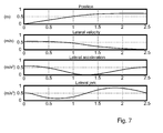
- fig. 7 the relation between the position, the lateral velocity, the lateral acceleration, and the lateral jerk is illustrated.
- a scenario in which a host vehicle H approaches a vehicle and a barrier is illustrated.
- the aim for the host vehicle H is to, as smoothly as possible, avoid or mitigate a collision with another vehicle and a barrier.
- the positions of the external objects are identified by sensor systems or are communicated to the host vehicle H.
- a plurality of trajectories that are valid for enabling the host vehicle H to pass the external objects are generated, and any trajectories intersecting with any one of the external objects are removed.
- the lateral position, lateral velocity, lateral acceleration and the lateral jerk that will act on the host vehicle H driving along any one of the trajectories are estimated, and the trajectory for which the lateral jerk acting on a host vehicle H is minimized is selected as the escape trajectory.
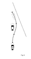
- the escape trajectory is illustrated in fig. 8 .
- the escape trajectory consists of three spline segments divided by spline breakpoints illustrated as dots along the trajectory. As seen, a first spline breakpoint is present in the starting point of the first spline segment, and a last spline breakpoint is present at the end of the last spline segment, as seen from the host vehicle H.
- the spline breakpoints are selected independently from the external objects in form of a vehicle and a barrier, such that the total jerk level acting on the host vehicle H is minimized.
- Fig. 10 illustrates a method for determining a trajectory for a host vehicle H in order to as smoothly as possible avoid or mitigate a collision in a road environment including the host vehicle H and external objects, using an arrangement comprising processing means and at least one of a sensor system or a communication system, wherein the method including the steps of
- Example embodiments described above may be combined as understood by a person skilled in the art. It is also understood by those skilled in the art that the splines are not restricted to be polynomial splines, but may be expressed in any suitable form.
Landscapes
- Engineering & Computer Science (AREA)
- Automation & Control Theory (AREA)
- Transportation (AREA)
- Mechanical Engineering (AREA)
- Physics & Mathematics (AREA)
- General Physics & Mathematics (AREA)
- Aviation & Aerospace Engineering (AREA)
- Radar, Positioning & Navigation (AREA)
- Remote Sensing (AREA)
- Combustion & Propulsion (AREA)
- Chemical & Material Sciences (AREA)
- Optics & Photonics (AREA)
- Electromagnetism (AREA)
- Control Of Driving Devices And Active Controlling Of Vehicle (AREA)
- Traffic Control Systems (AREA)
Abstract
Description
- Embodiments herein relate to a method and arrangement for determining a trajectory for a vehicle in order to as smoothly as possible avoid or mitigate a collision.
- Various systems for automatic braking of vehicles are known, where the systems are used in order to avoid or mitigate collisions between a vehicle and other objects, such as other vehicles or obstacles in a road environment.
- Many systems are based on a single target approach, i.e., on how much a driver has to brake or steer in order to avoid an object. This is related to the available acceleration in terms of road friction, and may be used to determine when a collision is unavoidable. Ideally, the system only intervenes when the driver needs help.
- In systems based on a single target approach, where the threat level for the single most threatening object is evaluated, important aspects may be missed. For example, the combined threat of several objects can be significantly higher than the individual threat of all objects if they are considered separately. For a general traffic situation with multiple objects present, a multi-target threat assessment may be advantageous, but it is difficult to find the required acceleration to avoid a collision.
-
EP2169500A1 discloses a method of assessing vehicle paths in a road environment including a host vehicle and external objects. The method is including the steps of detecting external objects by a sensor system and generating a plurality of paths passing said external objects. The method ofEP2169500A1 describes a search tree method, and uses piecewise constant lateral acceleration for the description of the lateral motion of a vehicle travelling the paths. Although this approximation may be sufficient when used for threat assessment in auto brake systems, it may be insufficient as a base for lateral control of the vehicle since the lateral acceleration cannot change instantly. - Embodiments herein aim to provide an improved method for determine a trajectory for a host vehicle in order to as smoothly as possible avoid or mitigate a collision.
- This is provided through a method for determining a trajectory for a host vehicle in order to as smoothly as possible avoid or mitigate a collision in a road environment including the host vehicle and external objects, using an arrangement comprising processing means and at least one of a sensor system or a communication system, where the method includes the steps of identifying the positions of one or more external objects in relation to the host vehicle within a predefined distance using at least one of the sensor or communication systems, generating a plurality of trajectories that are valid for enabling the host vehicle to pass any desired number of external objects using the processing means, removing any trajectories intersecting with any one of the external objects using the processing means, estimating lateral position, lateral velocity, lateral acceleration and the lateral jerk that will act on the host vehicle driving along any one of the trajectories, using the processing means and selecting the trajectory for which the lateral jerk acting on the host vehicle is minimized, using the processing means.
- Since the lateral jerk represents the change of the lateral acceleration, minimized lateral jerk results in a smooth escape trajectory for a vehicle driving along the trajectory, and a driver or passengers will perceive the escape trajectory to be relatively comfortable in comparison with other potential escape trajectories.
- According to a second aspect this is provided through a method for determining a trajectory in which a safety distance is preselected between any external objects and the host vehicle when selecting the trajectory.
- Since a preselected safety distance is introduced between the host vehicle and any external object, the host vehicle may pass any external object without touching them. This may be advantageous since no damage occurs due to contact between the host vehicle and any external objects.
- According to a third aspect this is provided through a method for determining a trajectory in which the selected trajectory forms a tangent to a first point located at a preselected safety distance from a first external object.
- Since the selected trajectory forms a tangent to a first point located at a preselected safety distance from a first external object, the selected trajectory passes the first external object as close as desired, and the jerk acting on a vehicle driving along the selected trajectory may be minimized at the same time as a preselected safety distance is present between the host vehicle and a first external object.
- According to a fourth aspect this is provided through a method for determining a trajectory in which the selected trajectory forms a tangent to a first point located at a preselected safety distance from a first external object and at least another point located at a preselected safety distance from at least another external object.
- Since the selected trajectory forms a tangent to a first point located at a preselected safety distance from a first external object and at least another point located at a preselected safety distance from at least another external object, the selected trajectory passes the first and the at least one other external object as close as desired, and the jerk acting on a vehicle driving along the selected trajectory may be minimized at the same time as a preselected safety distance is present between the host vehicle the external objects.
- According to a fifth aspect this is provided through a method for determining a trajectory in which the trajectory is constituted of n spline segments of degree d, and that the n spline segments are divided by spline breakpoints.
- Since the trajectory is constituted of spline segments divided by spline breakpoints, different expressions and equations may be used to describe different spline segments. This may be useful to define or express the lateral position, velocity, acceleration and jerk level.
- According to a sixth aspect this is provided through a method for determining a trajectory in which the trajectory is constituted of n polynomial spline segments of degree d, and that the n spline segments are divided by spline breakpoints.
- Since the trajectory is constituted of polynomial spline segments divided by spline breakpoints, different expressions and equations may be used to describe different spline segments. Describing the spline with a polynomial may be useful to define or express the lateral position, velocity, acceleration and jerk level.
- According to a seventh aspect this is provided through a method for determining a trajectory in which the spline breakpoints are selected independently from the positions of the external objects by the processing means, and that the selection is based on the estimated amount of lateral jerk that would act on the host vehicle if driven along any one of the trajectories.
- Since the spline breakpoints are selected independently from the positions of the external objects, and that the selection is based on the estimated amount of lateral jerk that would act on the host vehicle if driven along any one of the trajectories, different expressions and equations may be used to describe and/or select a jerk level in a spline segment, and the jerk level in different spline segments of the trajectory may be compared.
- According to an eight aspect this is provided through a method for determining a trajectory in which the spline breakpoints are selected such that the estimated maximum jerk for each spline segment is substantially equal.
- Since the spline breakpoints are selected such that the estimated maximum jerk for each spline segment is substantially equal, the maximal jerk in each segment of the spline may be utilized, and the total jerk level may be kept as low as possible and the trajectory as smooth as possible.
- Further embodiments herein aim to provide an improved arrangement for determining a trajectory for a vehicle in order to as smoothly as possible avoid or mitigate a collision. This is provided through an arrangement for determining a trajectory for a host vehicle in order to as smoothly as possible avoid or mitigate a collision in a road environment including the host vehicle and external objects, where the arrangement comprises processing means and at least one of a sensor system or a communication system and is arranged to execute the steps of identifying the positions of one or more external objects in relation to the host vehicle within a predefined distance using at least one of the sensor or communication system, generating a plurality of trajectories that are valid for enabling the host vehicle to pass any desired number of external objects using the processing means, removing any trajectories intersecting with any one of the external objects using the processing means, estimating lateral position, lateral velocity, lateral acceleration and the lateral jerk that will act on the host vehicle driving along any one of the trajectories, using the processing means and selecting the trajectory for which the lateral jerk acting on the host vehicle is minimized, using the processing means.
- Since the lateral jerk represents the change of the lateral acceleration, minimized lateral jerk results in a smooth escape trajectory for a vehicle traveling along the trajectory, and a driver or passengers will perceive the escape trajectory selected by the arrangement described above to be relatively comfortable in comparison with any other potential escape trajectory.
- Further features of, and advantages will become apparent when studying the appended claims and the following detailed description. Those skilled in the art will realize that different features may be combined to create embodiments other than those described in the following, without departing from the scope hereof, as defined by the appended claims.
- The various aspects of embodiments herein, including their particular features and advantages, will be readily understood from the following detailed description and the accompanying drawings, in which:
-
Fig. 1 illustrates vehicles in a road environment. -
Fig. 2 illustrates vehicles in a road environment. -
Fig. 3 illustrates vehicles in a road environment. -
Fig. 4 illustrates a graph of lateral acceleration and jerk. -
Fig. 5 illustrates graphs of lateral position and acceleration. -
Fig. 6 illustrates graphs of lateral position and acceleration. -
Fig. 7 illustrates the relation between position, velocity, acceleration and jerk. -
Fig. 8 illustrates vehicles in a road environment. -
Fig. 9 illustrates a vehicle. -
Fig. 10 illustrates method steps. - Embodiments herein will now be described more fully with reference to the accompanying drawings, in which example embodiments are shown. However, this application should not be construed as limited to the embodiments set forth herein. Disclosed features of example embodiments may be combined as readily understood by one of ordinary skill in the art to which this application belongs. Like numbers refer to like elements throughout.
- Well-known functions or constructions will not necessarily be described in detail for brevity and/or clarity.
-
Fig. 1 illustrates trajectories generated by a prior-art search tree method, in which a road environment with a moving host vehicle H approaches stationary or slower moving objects in form of vehicles. In order to avoid or mitigate a collision between the host vehicle H and any of the objects in front of the host vehicle H, more than one object is taken into account, and the goal is to find a steering manoeuver that simultaneously avoid several objects. As seen in the example, according tofig 1 , the host vehicle H has to avoid collision with three objects ahead. The goal of the method is to find, for each given traffic scenario, the "easiest" escape trajectory in some respect, and then use the severity or harshness of this escape trajectory as a threat metric. The method is based on the assumption that an optimal trajectory will always be straight forward, or it will touch as least one object. This method uses a search tree to generate trajectories with piecewise constant lateral acceleration that tangents all combinations of objects, and the acceleration is allowed to change only at the points in time (t1 c, t2 c, t3 c) where an object is passed. Among the collision-free escape trajectories that are found, the one with the lowest lateral acceleration is selected as the optimal escape trajectory. - A problem with the search tree model is that the steering manoeuver consists of piecewise lateral constant acceleration. Piecewise lateral constant acceleration is sufficient for assessing the threat in some automatic emergency braking applications, but may be unrealistic for controlling the vehicle. The vehicle may not be controlled according to such a steering manoeuvre as the lateral acceleration cannot change instantly.
- Another problem with the search tree model is that the acceleration only is allowed to change at points in time (t1 c, t2 c, t3 c) when an object is passed, which may result in a non-smooth escape path.
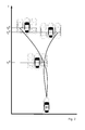
- In
fig. 2 trajectories based on smooth splines are illustrated. The method for determining a trajectory illustrated infig. 2 considers several objects simultaneously, and applies a smooth type of curve based on splines, such as polynomial splines. The method is similar to the method illustrated infig. 1 in that it goes through all possible manoeuvers that touch combinations of objects on a left hand side or a right hand side, but according to this method a smooth spline is used to describe the trajectory. Left hand side or on a right hand side of an object is here defined as the objects are seen by a person sitting in the host vehicle, looking at the objects in front of the host vehicle. Referring tofig 1 or2 , a road may have an extension substantially vertical in the figures, in parallel with a longitudinal direction of the host vehicle H. Infig. 2 , two trajectories for the host vehicle H are illustrated. A host vehicle H that is driven along the any one of the two trajectories is thus passing a first object at t1 c on a right hand side, illustrated by the trajectories on a right hand side of the object at t1 c. Then one of the trajectories passes a second object on a right hand side at t2 c, the other trajectory is passing a third object at t3 c on a left hand side. The trajectories illustrate examples of possible trajectories. - As seen when comparing
fig. 1 andfig. 2 , the first part of the trajectory between the host vehicle H and the first object at t1 c is different, since the first part of the trajectory depends on the second part of the trajectory between t1 c and t2 c. In order to achieve this, all objects along the trajectory have to be considered at the same time when generating the trajectory. - The splines constituting the trajectories according to
fig. 2 fulfil two requirements; they can be found quickly, which is important for implementations where the method is arranged to be used in real time applications, and they are smooth enough to be able to control a vehicle in a comfortable manner. - In
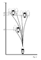
fig. 3 it is illustrated how trajectories for all manoeuvres that only consider a first single object are found. Both passing on a left hand side and passing on a right hand side is considered. Several of the trajectories involve conflicts with other objects but they will be removed in a later step. - Then manoeuvers considering two objects are found, as illustrated in
fig. 2 . All combinations of objects ordered in time are considered. Infig. 2 only two examples are illustrated for the sake of clarity. Then manoeuvers considering three objects are found. The method may be carried out until the desired number of complexity has been reached. Thus, trajectories that forms a tangent to one object, two objects, three objects ... n objects are generated, until a required search depth is reached. Then candidate manoeuvers are evaluated and the ones intersecting with objects are removed. All remaining manoeuvers are valid escape trajectories, and the optimal one is the one with the lowest jerk. - The trajectories are smooth enough thanks to a high level of differentiability. The splines according to
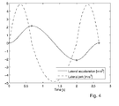
fig. 2 may be piecewise cubic splines in acceleration, and the acceleration level is illustrated infig. 4 . The acceleration may be a cubic polynomial spline with zero derivatives at the knots. The number of knots and their position depends on the problem that needs to be solved and its complexity. It has the advantage of being relatively easy to find, i.e. has low numerical complexity, and it is sufficiently smooth. -
Fig. 4 also illustrates the jerk level. The jerk represents the change level in acceleration, and in order to keep the manoeuver comfortable is it important to keep the jerk level as low and smooth as possible. Since the goal is to keep the jerk low, the method according to the subject matter as defined in the appending claims may utilize the maximal jerk Jmax in each segment of the spline. The manoeuver may be parameterized by the expression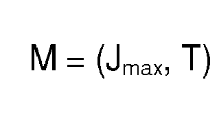
- Jmax represents the peak magnitude of the jerk, which is the same in all segments of the spline, and t1 is the length of the
segment 1 of the spline, t2 is the length of thesegment 2 of the spline, i.e. ti is the length of the segment i of the spline. - The jerk level along the trajectory in a three segment spline may be expressed as

and expressions for the lateral acceleration, lateral velocity and lateral position along the trajectory may be found by integrating the expression J(t) above. The method may be combined with other types of curves as well, for example splines with lower order. - The jerk level may be selected as cost function, and the optimal trajectory will then either be of zero jerk or the trajectory will touch at least one of the object. In order to find the optimal manoeuver, all manoeuvers that touch different combinations of objects have to be searched.
- The method for determining a trajectory for a host vehicle H in order to as smoothly as possible avoid or mitigate a collision in a road environment including the host vehicle H and external objects is using an arrangement comprising processing means 1 and at least one of a
sensor system 2 or acommunication system 3. The method is illustrated infig. 10 and includes the steps of identifying 101 the positions of one or more external objects in relation to the host vehicle H within a predefined distance within a sensor covered area, using at least one of the sensor orcommunication systems - Identification of the positions of the one or more external objects may be done by a sensor system 2.The
sensor system 2 may use radar (the determination of for example direction or speed of objects with radio waves), lidar (where light, such as laser, is used for sensing e.g. direction or speed of objects), cameras, global positioning systems etc. or combinations of these for identifying the positions of the external objects. The external objects may also be identified by other vehicles or sensing systems of any kind, which in turn communicates information relating to the external objects to the hostvehicle communication system 3. An example of this is vehicle-to-vehicle communication systems, where information may be sent or forwarded between vehicles. Thecommunication system 3 can use for example radio communication, telecommunication and/or optical communication. Thesensor system 2 and thecommunication system 3 are illustrated infig. 9 . - The processing means 1 comprises one or more processors with associated software and one or more memory units in communication with the one or more processors such that the processing means 1, upon execution of the associated software on the one or more processors, may generate, select and remove trajectories. The processing means 1 is further arranged to estimate lateral position, lateral velocity, lateral acceleration and lateral jerk that may act on the host vehicle H.
- The method is extremely fast and may be run in real time in automotive hardware. The trajectory that is found is the global optimum in the given function class. In order to estimate the numerical complexity, the number of manoeuvers that have to be computed may be expressed as

where N is the total number of objects and Nmax is the maximum number of objects that are considered simultaneously in each manoeuver. The present implementation may be restricted such that a single manoeuver considers at most two objects in each candidate manoeuver, i.e. Nmax = 2. The removal of any trajectories intersecting with any one of the external objects is done on all objects. If Nmax = 2 then the SN, Nmax expression may be reduced to SN,2= 2N2. - In
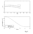
fig. 5 , the trajectories and corresponding lateral acceleration profiles (solid lines) are compared with the trajectories and corresponding lateral acceleration profiles according to the abovementioned search tree method with constant lateral acceleration (dashed lines). In the figure, the centre of the front of the host vehicle H is at the origin, and the host vehicle H is travelling in the positive x-direction. The host vehicle H is thus not visible in the graphs, only its trajectory. The trajectory is shown as a corridor which represents the area used by the host vehicle H during the manoeuver. The trajectory may pass the obstacles with a predefined safety distance, and the desired safety distance may be added before running the escape trajectory algorithm. Depending on the traffic situation, the obstacles, the host vehicle H etc., the safety distance may be selected to be very small, such as one or a few millimetres, or it may be larger, such as one of a few centimetres, decimetres or meters. In dense traffic, or traffic situations in which the host vehicle H and/or the surrounding obstacles/vehicles have relatively low velocity, a smaller safety distances may be preferred. In other situations it may be preferable to select larger safety distances when possible. - In
fig. 5 , a scenario in which a host vehicle H approaches a single stationery vehicle is illustrated. The dashed line represents the search tree constant acceleration method, which is used as reference, while the solid line represents the spline based trajectory according to embodiments herein. The underlying motion assumption is apparent in the lower plot. In the search tree method, the acceleration instantly changes and switches back to zero after passing the object. The multiple object/target spline method uses a continuous jerk, which means a smooth lateral acceleration. - Even if the search tree method sometimes may produce manoeuvres with lower lateral acceleration, they may be unrealistic from a vehicle dynamics perspective. Even if a lateral controller of a vehicle would use such a manoeuver as reference, the vehicle may not be able to follow it.
- Also in
fig. 6 , the trajectories and corresponding lateral acceleration profiles are compared with the trajectories and corresponding lateral acceleration profiles according to the abovementioned search tree method with constant lateral acceleration. In the figure, the centre of the front of the host vehicle H is at the origin, and the host vehicle H is travelling in the positive x-direction. The host vehicle H is thus not visible in the graphs, only its trajectory. The trajectory is shown as a corridor which represents the area used by the host vehicle H during the manoeuver. A scenario in which a host vehicle H approaches two objects in form of vehicles is illustrated. In addition to the objects in form of vehicles, an object in form of a barrier along the road is illustrated with heavy dashed lines. The figure illustrates that if all objects are taken into account, the threat level will be much higher than if just one object is considered at a time. This means for example that autonomous emergency braking activations may be initiated earlier. Infig. 7 , the relation between the position, the lateral velocity, the lateral acceleration, and the lateral jerk is illustrated. - In
fig. 8 , a scenario in which a host vehicle H approaches a vehicle and a barrier is illustrated. The aim for the host vehicle H is to, as smoothly as possible, avoid or mitigate a collision with another vehicle and a barrier. The positions of the external objects are identified by sensor systems or are communicated to the host vehicle H. A plurality of trajectories that are valid for enabling the host vehicle H to pass the external objects are generated, and any trajectories intersecting with any one of the external objects are removed. The lateral position, lateral velocity, lateral acceleration and the lateral jerk that will act on the host vehicle H driving along any one of the trajectories are estimated, and the trajectory for which the lateral jerk acting on a host vehicle H is minimized is selected as the escape trajectory. The escape trajectory is illustrated infig. 8 . In the embodiment according to the figure, the escape trajectory consists of three spline segments divided by spline breakpoints illustrated as dots along the trajectory. As seen, a first spline breakpoint is present in the starting point of the first spline segment, and a last spline breakpoint is present at the end of the last spline segment, as seen from the host vehicle H. The spline breakpoints are selected independently from the external objects in form of a vehicle and a barrier, such that the total jerk level acting on the host vehicle H is minimized. - In
fig. 9 the host vehicle H, the processing means 1, thesensor system 2 and thecommunication system 3 are illustrated. -
Fig. 10 illustrates a method for determining a trajectory for a host vehicle H in order to as smoothly as possible avoid or mitigate a collision in a road environment including the host vehicle H and external objects, using an arrangement comprising processing means and at least one of a sensor system or a communication system, wherein the method including the steps of - identifying 101 the positions of one or more external objects in relation to the host vehicle H within a predefined distance using at least one of the sensor or communication systems,
- generating 102 a plurality of trajectories that are valid for enabling the host vehicle H to pass any desired number of external objects using the processing means,
- removing 103 any trajectories intersecting with any one of the external objects using the processing means,
- estimating 104 lateral position, lateral velocity, lateral acceleration and the lateral jerk that will act on the host vehicle H driving along any one of the trajectories, using the processing means,
- selecting 105 the trajectory for which the lateral jerk acting on the host vehicle H is minimized, using the processing means
- Example embodiments described above may be combined as understood by a person skilled in the art. It is also understood by those skilled in the art that the splines are not restricted to be polynomial splines, but may be expressed in any suitable form.
Claims (9)
- A method for determining a trajectory for a host vehicle H in order to as smoothly as possible avoid or mitigate a collision in a road environment including the host vehicle H and external objects, using an arrangement comprising processing means (1) and at least one of a sensor system (2) or a communication system (3), characterized in that the method including the steps of- identifying (101) the positions of one or more external objects in relation to the host vehicle H within a predefined distance using at least one of the sensor or communication systems (2, 3),- generating (102) a plurality of trajectories that are valid for enabling the host vehicle H to pass any desired number of external objects using the processing means (1),- removing (103) any trajectories intersecting with any one of the external objects using the processing means (1),- estimating (104) lateral position, lateral velocity, lateral acceleration and the lateral jerk that will act on the host vehicle H driving along any one of the trajectories, using the processing means (1),- selecting (105) the trajectory for which the lateral jerk acting on the host vehicle H is minimized, using the processing means (1)
- A method for determining a trajectory according to claim 1, characterized in that a safety distance is preselected between any external objects and the host vehicle H when selecting the trajectory.
- A method for determining a trajectory according to claim 2, characterized in that the selected trajectory forms a tangent to a first point located at a preselected safety distance from a first external object.
- A method for determining a trajectory according to claim 2 or 3, characterized in that the selected trajectory forms a tangent to a first point located at a preselected safety distance from a first external object and at least another point located at a preselected safety distance from at least another external object.
- A method for determining a trajectory according to any one of claim 1 - 4, characterized in that the trajectory is constituted of n spline segments of degree d, and that the n spline segments are divided by spline breakpoints.
- A method for determining a trajectory according to any one of claim 1 - 5, characterized in that the trajectory is constituted of n polynomial spline segments of degree d, and that the n spline segments are divided by spline breakpoints.
- A method for determining a trajectory according to claim 5 or 6, characterized in that the spline breakpoints are selected independently from the positions of the external objects by the processing means (1), and that the selection is based on the estimated amount of lateral jerk that would act on the host vehicle H if driven along any one of the trajectories.
- A method for determining a trajectory according to claim 5 or 6, characterized in that the spline breakpoints are selected such that the estimated maximum jerk, Jmax for each spline segment is substantially equal.
- An arrangement for determining a trajectory for a host vehicle H in order to as smoothly as possible avoid or mitigate a collision in a road environment including the host vehicle H and external objects, characterized in that the arrangement comprises processing means (1) and at least one of a sensor system (2) or a communication system (3) and is arranged to execute the steps of- identifying (101) the positions of one or more external objects in relation to the host vehicle H within a predefined distance using at least one of the sensor or communication system (2, 3),- generating (102) a plurality of trajectories that are valid for enabling the host vehicle H to pass any desired number of external objects using the processing means (1),- removing (103) any trajectories intersecting with any one of the external objects using the processing means (1),- estimating (104) lateral position, lateral velocity, lateral acceleration and the lateral jerk that will act on the host vehicle H driving along any one of the trajectories, using the processing means (1),- selecting (105) the trajectory for which the lateral jerk acting on the host vehicle H is minimized, using the processing means (1)
Priority Applications (2)
| Application Number | Priority Date | Filing Date | Title |
|---|---|---|---|
| EP13152454.8A EP2759897B1 (en) | 2013-01-24 | 2013-01-24 | Method and arrangement for determining a trajectory |
| US14/153,509 US9489847B2 (en) | 2013-01-24 | 2014-01-13 | Method and arrangement for determining a trajectory |
Applications Claiming Priority (1)
| Application Number | Priority Date | Filing Date | Title |
|---|---|---|---|
| EP13152454.8A EP2759897B1 (en) | 2013-01-24 | 2013-01-24 | Method and arrangement for determining a trajectory |
Publications (2)
| Publication Number | Publication Date |
|---|---|
| EP2759897A1 true EP2759897A1 (en) | 2014-07-30 |
| EP2759897B1 EP2759897B1 (en) | 2019-04-24 |
Family
ID=47754301
Family Applications (1)
| Application Number | Title | Priority Date | Filing Date |
|---|---|---|---|
| EP13152454.8A Active EP2759897B1 (en) | 2013-01-24 | 2013-01-24 | Method and arrangement for determining a trajectory |
Country Status (2)
| Country | Link |
|---|---|
| US (1) | US9489847B2 (en) |
| EP (1) | EP2759897B1 (en) |
Cited By (3)
| Publication number | Priority date | Publication date | Assignee | Title |
|---|---|---|---|---|
| DE102014202243A1 (en) * | 2014-02-07 | 2015-08-13 | Robert Bosch Gmbh | A method of assisting a driver in maneuvering a vehicle |
| FR3055058A1 (en) * | 2016-08-10 | 2018-02-16 | Peugeot Citroen Automobiles Sa | METHOD AND DEVICE FOR ASSISTING AT LEAST PARTIALLY AUTONOMOUS VEHICLE FOR THE OPTIMIZATION OF DRIVER COMFORT |
| CN110530379A (en) * | 2019-10-10 | 2019-12-03 | 蒽帛物联网科技(上海)有限公司 | It is a kind of that the method, apparatus and system of vehicle traveling information are provided |
Families Citing this family (18)
| Publication number | Priority date | Publication date | Assignee | Title |
|---|---|---|---|---|
| TWI525009B (en) * | 2013-11-11 | 2016-03-11 | 緯創資通股份有限公司 | Vehicle early warning system and vehicle early warning method |
| US9457807B2 (en) * | 2014-06-05 | 2016-10-04 | GM Global Technology Operations LLC | Unified motion planning algorithm for autonomous driving vehicle in obstacle avoidance maneuver |
| AU2014407858B2 (en) * | 2014-09-30 | 2018-02-01 | Hitachi Construction Machinery Co., Ltd. | Haulage Vehicle |
| DE102015218166B4 (en) * | 2015-09-22 | 2018-11-22 | Volkswagen Aktiengesellschaft | Controller configuration for a motor vehicle driver assistance system |
| US9857795B2 (en) * | 2016-03-24 | 2018-01-02 | Honda Motor Co., Ltd. | System and method for trajectory planning for unexpected pedestrians |
| DE102017215844A1 (en) * | 2017-09-08 | 2019-03-14 | Robert Bosch Gmbh | Method for operating a vehicle |
| US10606277B2 (en) * | 2017-09-18 | 2020-03-31 | Baidu Usa Llc | Speed optimization based on constrained smoothing spline for autonomous driving vehicles |
| JP2020066300A (en) * | 2018-10-23 | 2020-04-30 | トヨタ自動車株式会社 | Vehicle control device |
| CN109814568B (en) * | 2019-02-19 | 2022-05-03 | 阿波罗智能技术(北京)有限公司 | Method and device for generating speed track of unmanned vehicle and storage medium |
| CN111121804B (en) * | 2019-12-03 | 2023-09-26 | 重庆邮电大学 | An intelligent vehicle path planning method and system with safety constraints |
| US11535274B2 (en) * | 2020-03-26 | 2022-12-27 | Pony Ai Inc. | Self-learning vehicle performance optimization |
| HU231455B1 (en) * | 2020-09-03 | 2023-12-28 | Vie Technology (Europe) Kft. | Method and arrangement for starting automatic emergency braking of a vehicle in an appropriate time and for controlling longitudinal movement |
| JP7453885B2 (en) * | 2020-09-04 | 2024-03-21 | 日立Astemo株式会社 | Vehicle control device and obstacle avoidance control method |
| CN112161628B (en) * | 2020-09-27 | 2022-10-14 | 广州小鹏自动驾驶科技有限公司 | Path data processing method and device, vehicle and readable medium |
| CN112179368B (en) * | 2020-09-27 | 2022-12-13 | 广州小鹏自动驾驶科技有限公司 | Method, device, vehicle, and readable medium for processing route data |
| CN114815791B (en) * | 2021-01-18 | 2025-06-17 | 浙江菜鸟供应链管理有限公司 | Drivable space planning method and device |
| EP4357213B1 (en) | 2022-10-17 | 2025-07-09 | Zenseact AB | A method for determining whether an automatic collision avoidance steering maneuver should be executed or not |
| EP4620768A1 (en) * | 2024-03-22 | 2025-09-24 | Zenseact AB | Steering interventions for vehicles |
Citations (4)
| Publication number | Priority date | Publication date | Assignee | Title |
|---|---|---|---|---|
| JPH07179140A (en) * | 1993-12-24 | 1995-07-18 | Nissan Motor Co Ltd | Autopilot for vehicle |
| US20040090117A1 (en) * | 2000-07-26 | 2004-05-13 | Ingo Dudeck | Automatic brake and steering system and method for a vehicle |
| US20080255728A1 (en) * | 2005-12-09 | 2008-10-16 | Hella Kgaa Hueck & Co. | Path Planning |
| EP2169500A1 (en) | 2008-09-25 | 2010-03-31 | Ford Global Technologies, LLC | Method of assessing vehicle paths in a road environment and a vehicle path assessment system. |
Family Cites Families (2)
| Publication number | Priority date | Publication date | Assignee | Title |
|---|---|---|---|---|
| EP2388756B1 (en) * | 2010-05-17 | 2019-01-09 | Volvo Car Corporation | Forward collision risk reduction |
| US9318023B2 (en) * | 2011-08-31 | 2016-04-19 | GM Global Technology Operations LLC | System and method for collision avoidance maneuver path determination with jerk limit |
-
2013
- 2013-01-24 EP EP13152454.8A patent/EP2759897B1/en active Active
-
2014
- 2014-01-13 US US14/153,509 patent/US9489847B2/en active Active
Patent Citations (4)
| Publication number | Priority date | Publication date | Assignee | Title |
|---|---|---|---|---|
| JPH07179140A (en) * | 1993-12-24 | 1995-07-18 | Nissan Motor Co Ltd | Autopilot for vehicle |
| US20040090117A1 (en) * | 2000-07-26 | 2004-05-13 | Ingo Dudeck | Automatic brake and steering system and method for a vehicle |
| US20080255728A1 (en) * | 2005-12-09 | 2008-10-16 | Hella Kgaa Hueck & Co. | Path Planning |
| EP2169500A1 (en) | 2008-09-25 | 2010-03-31 | Ford Global Technologies, LLC | Method of assessing vehicle paths in a road environment and a vehicle path assessment system. |
Cited By (3)
| Publication number | Priority date | Publication date | Assignee | Title |
|---|---|---|---|---|
| DE102014202243A1 (en) * | 2014-02-07 | 2015-08-13 | Robert Bosch Gmbh | A method of assisting a driver in maneuvering a vehicle |
| FR3055058A1 (en) * | 2016-08-10 | 2018-02-16 | Peugeot Citroen Automobiles Sa | METHOD AND DEVICE FOR ASSISTING AT LEAST PARTIALLY AUTONOMOUS VEHICLE FOR THE OPTIMIZATION OF DRIVER COMFORT |
| CN110530379A (en) * | 2019-10-10 | 2019-12-03 | 蒽帛物联网科技(上海)有限公司 | It is a kind of that the method, apparatus and system of vehicle traveling information are provided |
Also Published As
| Publication number | Publication date |
|---|---|
| US9489847B2 (en) | 2016-11-08 |
| US20140207364A1 (en) | 2014-07-24 |
| EP2759897B1 (en) | 2019-04-24 |
Similar Documents
| Publication | Publication Date | Title |
|---|---|---|
| US9489847B2 (en) | Method and arrangement for determining a trajectory | |
| US10739778B2 (en) | Method and device for controlling a trajectory planning process of an ego-vehicle | |
| US10101168B2 (en) | Route calculation device for vehicle | |
| CN104554272B (en) | The path planning of avoidance steering operation when target vehicle and surrounding objects be present | |
| KR102118632B1 (en) | Method for determining an activation criterion for a brake application and emergency brake system for performing the method | |
| EP3613647B1 (en) | Automatic parking control device | |
| JP6404722B2 (en) | Vehicle travel control device | |
| JP6369061B2 (en) | Lane change support device | |
| CN104554258B (en) | Using the path planning of the avoidance steering operation of virtual potential field technology | |
| KR102568114B1 (en) | Apparatus for controlling autonomous driving and method thereof | |
| JP4883248B2 (en) | Vehicle periphery monitoring device | |
| JP6507839B2 (en) | Vehicle travel control device | |
| EP1717778B1 (en) | Method and system for forward collision avoidance in an automotive vehicle | |
| JP6337435B2 (en) | Driving assistance device | |
| EP2837538B1 (en) | A vehicle safety system | |
| JP2018083587A (en) | Vehicle control device | |
| CN106094812A (en) | Reaction equation path planning for autonomous driving | |
| EP3456596A1 (en) | Method and device of predicting a possible collision | |
| WO2014148989A1 (en) | Control system for autonomous vehicles, and a method for the control system | |
| DE102015223890A1 (en) | Device and method for controlling autonomous navigation | |
| WO2018074287A1 (en) | Vehicle control device | |
| CN114559923A (en) | An automatic emergency obstacle avoidance system for an unmanned vehicle and a control method thereof | |
| JP6544168B2 (en) | Vehicle control device and vehicle control method | |
| JP6477253B2 (en) | Vehicle travel control device | |
| JP6291737B2 (en) | Vehicle travel control device and platoon travel control method |
Legal Events
| Date | Code | Title | Description |
|---|---|---|---|
| PUAI | Public reference made under article 153(3) epc to a published international application that has entered the european phase |
Free format text: ORIGINAL CODE: 0009012 |
|
| 17P | Request for examination filed |
Effective date: 20130124 |
|
| AK | Designated contracting states |
Kind code of ref document: A1 Designated state(s): AL AT BE BG CH CY CZ DE DK EE ES FI FR GB GR HR HU IE IS IT LI LT LU LV MC MK MT NL NO PL PT RO RS SE SI SK SM TR |
|
| AX | Request for extension of the european patent |
Extension state: BA ME |
|
| R17P | Request for examination filed (corrected) |
Effective date: 20150130 |
|
| RBV | Designated contracting states (corrected) |
Designated state(s): AL AT BE BG CH CY CZ DE DK EE ES FI FR GB GR HR HU IE IS IT LI LT LU LV MC MK MT NL NO PL PT RO RS SE SI SK SM TR |
|
| STAA | Information on the status of an ep patent application or granted ep patent |
Free format text: STATUS: EXAMINATION IS IN PROGRESS |
|
| 17Q | First examination report despatched |
Effective date: 20161222 |
|
| GRAP | Despatch of communication of intention to grant a patent |
Free format text: ORIGINAL CODE: EPIDOSNIGR1 |
|
| STAA | Information on the status of an ep patent application or granted ep patent |
Free format text: STATUS: GRANT OF PATENT IS INTENDED |
|
| INTG | Intention to grant announced |
Effective date: 20181207 |
|
| GRAS | Grant fee paid |
Free format text: ORIGINAL CODE: EPIDOSNIGR3 |
|
| GRAA | (expected) grant |
Free format text: ORIGINAL CODE: 0009210 |
|
| STAA | Information on the status of an ep patent application or granted ep patent |
Free format text: STATUS: THE PATENT HAS BEEN GRANTED |
|
| AK | Designated contracting states |
Kind code of ref document: B1 Designated state(s): AL AT BE BG CH CY CZ DE DK EE ES FI FR GB GR HR HU IE IS IT LI LT LU LV MC MK MT NL NO PL PT RO RS SE SI SK SM TR |
|
| REG | Reference to a national code |
Ref country code: GB Ref legal event code: FG4D |
|
| REG | Reference to a national code |
Ref country code: CH Ref legal event code: EP |
|
| REG | Reference to a national code |
Ref country code: AT Ref legal event code: REF Ref document number: 1124869 Country of ref document: AT Kind code of ref document: T Effective date: 20190515 Ref country code: IE Ref legal event code: FG4D |
|
| REG | Reference to a national code |
Ref country code: DE Ref legal event code: R096 Ref document number: 602013054180 Country of ref document: DE |
|
| REG | Reference to a national code |
Ref country code: NL Ref legal event code: MP Effective date: 20190424 |
|
| REG | Reference to a national code |
Ref country code: LT Ref legal event code: MG4D |
|
| PG25 | Lapsed in a contracting state [announced via postgrant information from national office to epo] |
Ref country code: NL Free format text: LAPSE BECAUSE OF FAILURE TO SUBMIT A TRANSLATION OF THE DESCRIPTION OR TO PAY THE FEE WITHIN THE PRESCRIBED TIME-LIMIT Effective date: 20190424 |
|
| PG25 | Lapsed in a contracting state [announced via postgrant information from national office to epo] |
Ref country code: ES Free format text: LAPSE BECAUSE OF FAILURE TO SUBMIT A TRANSLATION OF THE DESCRIPTION OR TO PAY THE FEE WITHIN THE PRESCRIBED TIME-LIMIT Effective date: 20190424 Ref country code: LT Free format text: LAPSE BECAUSE OF FAILURE TO SUBMIT A TRANSLATION OF THE DESCRIPTION OR TO PAY THE FEE WITHIN THE PRESCRIBED TIME-LIMIT Effective date: 20190424 Ref country code: HR Free format text: LAPSE BECAUSE OF FAILURE TO SUBMIT A TRANSLATION OF THE DESCRIPTION OR TO PAY THE FEE WITHIN THE PRESCRIBED TIME-LIMIT Effective date: 20190424 Ref country code: FI Free format text: LAPSE BECAUSE OF FAILURE TO SUBMIT A TRANSLATION OF THE DESCRIPTION OR TO PAY THE FEE WITHIN THE PRESCRIBED TIME-LIMIT Effective date: 20190424 Ref country code: AL Free format text: LAPSE BECAUSE OF FAILURE TO SUBMIT A TRANSLATION OF THE DESCRIPTION OR TO PAY THE FEE WITHIN THE PRESCRIBED TIME-LIMIT Effective date: 20190424 Ref country code: NO Free format text: LAPSE BECAUSE OF FAILURE TO SUBMIT A TRANSLATION OF THE DESCRIPTION OR TO PAY THE FEE WITHIN THE PRESCRIBED TIME-LIMIT Effective date: 20190724 Ref country code: SE Free format text: LAPSE BECAUSE OF FAILURE TO SUBMIT A TRANSLATION OF THE DESCRIPTION OR TO PAY THE FEE WITHIN THE PRESCRIBED TIME-LIMIT Effective date: 20190424 Ref country code: PT Free format text: LAPSE BECAUSE OF FAILURE TO SUBMIT A TRANSLATION OF THE DESCRIPTION OR TO PAY THE FEE WITHIN THE PRESCRIBED TIME-LIMIT Effective date: 20190824 |
|
| PG25 | Lapsed in a contracting state [announced via postgrant information from national office to epo] |
Ref country code: LV Free format text: LAPSE BECAUSE OF FAILURE TO SUBMIT A TRANSLATION OF THE DESCRIPTION OR TO PAY THE FEE WITHIN THE PRESCRIBED TIME-LIMIT Effective date: 20190424 Ref country code: GR Free format text: LAPSE BECAUSE OF FAILURE TO SUBMIT A TRANSLATION OF THE DESCRIPTION OR TO PAY THE FEE WITHIN THE PRESCRIBED TIME-LIMIT Effective date: 20190725 Ref country code: PL Free format text: LAPSE BECAUSE OF FAILURE TO SUBMIT A TRANSLATION OF THE DESCRIPTION OR TO PAY THE FEE WITHIN THE PRESCRIBED TIME-LIMIT Effective date: 20190424 Ref country code: RS Free format text: LAPSE BECAUSE OF FAILURE TO SUBMIT A TRANSLATION OF THE DESCRIPTION OR TO PAY THE FEE WITHIN THE PRESCRIBED TIME-LIMIT Effective date: 20190424 Ref country code: BG Free format text: LAPSE BECAUSE OF FAILURE TO SUBMIT A TRANSLATION OF THE DESCRIPTION OR TO PAY THE FEE WITHIN THE PRESCRIBED TIME-LIMIT Effective date: 20190724 |
|
| REG | Reference to a national code |
Ref country code: AT Ref legal event code: MK05 Ref document number: 1124869 Country of ref document: AT Kind code of ref document: T Effective date: 20190424 |
|
| PG25 | Lapsed in a contracting state [announced via postgrant information from national office to epo] |
Ref country code: IS Free format text: LAPSE BECAUSE OF FAILURE TO SUBMIT A TRANSLATION OF THE DESCRIPTION OR TO PAY THE FEE WITHIN THE PRESCRIBED TIME-LIMIT Effective date: 20190824 |
|
| REG | Reference to a national code |
Ref country code: DE Ref legal event code: R097 Ref document number: 602013054180 Country of ref document: DE |
|
| PG25 | Lapsed in a contracting state [announced via postgrant information from national office to epo] |
Ref country code: RO Free format text: LAPSE BECAUSE OF FAILURE TO SUBMIT A TRANSLATION OF THE DESCRIPTION OR TO PAY THE FEE WITHIN THE PRESCRIBED TIME-LIMIT Effective date: 20190424 Ref country code: CZ Free format text: LAPSE BECAUSE OF FAILURE TO SUBMIT A TRANSLATION OF THE DESCRIPTION OR TO PAY THE FEE WITHIN THE PRESCRIBED TIME-LIMIT Effective date: 20190424 Ref country code: EE Free format text: LAPSE BECAUSE OF FAILURE TO SUBMIT A TRANSLATION OF THE DESCRIPTION OR TO PAY THE FEE WITHIN THE PRESCRIBED TIME-LIMIT Effective date: 20190424 Ref country code: AT Free format text: LAPSE BECAUSE OF FAILURE TO SUBMIT A TRANSLATION OF THE DESCRIPTION OR TO PAY THE FEE WITHIN THE PRESCRIBED TIME-LIMIT Effective date: 20190424 Ref country code: SK Free format text: LAPSE BECAUSE OF FAILURE TO SUBMIT A TRANSLATION OF THE DESCRIPTION OR TO PAY THE FEE WITHIN THE PRESCRIBED TIME-LIMIT Effective date: 20190424 Ref country code: DK Free format text: LAPSE BECAUSE OF FAILURE TO SUBMIT A TRANSLATION OF THE DESCRIPTION OR TO PAY THE FEE WITHIN THE PRESCRIBED TIME-LIMIT Effective date: 20190424 |
|
| PG25 | Lapsed in a contracting state [announced via postgrant information from national office to epo] |
Ref country code: SM Free format text: LAPSE BECAUSE OF FAILURE TO SUBMIT A TRANSLATION OF THE DESCRIPTION OR TO PAY THE FEE WITHIN THE PRESCRIBED TIME-LIMIT Effective date: 20190424 |
|
| PLBE | No opposition filed within time limit |
Free format text: ORIGINAL CODE: 0009261 |
|
| STAA | Information on the status of an ep patent application or granted ep patent |
Free format text: STATUS: NO OPPOSITION FILED WITHIN TIME LIMIT |
|
| PG25 | Lapsed in a contracting state [announced via postgrant information from national office to epo] |
Ref country code: TR Free format text: LAPSE BECAUSE OF FAILURE TO SUBMIT A TRANSLATION OF THE DESCRIPTION OR TO PAY THE FEE WITHIN THE PRESCRIBED TIME-LIMIT Effective date: 20190424 |
|
| 26N | No opposition filed |
Effective date: 20200127 |
|
| PG25 | Lapsed in a contracting state [announced via postgrant information from national office to epo] |
Ref country code: SI Free format text: LAPSE BECAUSE OF FAILURE TO SUBMIT A TRANSLATION OF THE DESCRIPTION OR TO PAY THE FEE WITHIN THE PRESCRIBED TIME-LIMIT Effective date: 20190424 |
|
| PG25 | Lapsed in a contracting state [announced via postgrant information from national office to epo] |
Ref country code: MC Free format text: LAPSE BECAUSE OF FAILURE TO SUBMIT A TRANSLATION OF THE DESCRIPTION OR TO PAY THE FEE WITHIN THE PRESCRIBED TIME-LIMIT Effective date: 20190424 |
|
| REG | Reference to a national code |
Ref country code: CH Ref legal event code: PL |
|
| GBPC | Gb: european patent ceased through non-payment of renewal fee |
Effective date: 20200124 |
|
| REG | Reference to a national code |
Ref country code: BE Ref legal event code: MM Effective date: 20200131 |
|
| PG25 | Lapsed in a contracting state [announced via postgrant information from national office to epo] |
Ref country code: GB Free format text: LAPSE BECAUSE OF NON-PAYMENT OF DUE FEES Effective date: 20200124 Ref country code: LU Free format text: LAPSE BECAUSE OF NON-PAYMENT OF DUE FEES Effective date: 20200124 |
|
| PG25 | Lapsed in a contracting state [announced via postgrant information from national office to epo] |
Ref country code: LI Free format text: LAPSE BECAUSE OF NON-PAYMENT OF DUE FEES Effective date: 20200131 Ref country code: CH Free format text: LAPSE BECAUSE OF NON-PAYMENT OF DUE FEES Effective date: 20200131 Ref country code: BE Free format text: LAPSE BECAUSE OF NON-PAYMENT OF DUE FEES Effective date: 20200131 |
|
| PG25 | Lapsed in a contracting state [announced via postgrant information from national office to epo] |
Ref country code: IE Free format text: LAPSE BECAUSE OF NON-PAYMENT OF DUE FEES Effective date: 20200124 |
|
| PG25 | Lapsed in a contracting state [announced via postgrant information from national office to epo] |
Ref country code: MT Free format text: LAPSE BECAUSE OF FAILURE TO SUBMIT A TRANSLATION OF THE DESCRIPTION OR TO PAY THE FEE WITHIN THE PRESCRIBED TIME-LIMIT Effective date: 20190424 Ref country code: CY Free format text: LAPSE BECAUSE OF FAILURE TO SUBMIT A TRANSLATION OF THE DESCRIPTION OR TO PAY THE FEE WITHIN THE PRESCRIBED TIME-LIMIT Effective date: 20190424 |
|
| PG25 | Lapsed in a contracting state [announced via postgrant information from national office to epo] |
Ref country code: MK Free format text: LAPSE BECAUSE OF FAILURE TO SUBMIT A TRANSLATION OF THE DESCRIPTION OR TO PAY THE FEE WITHIN THE PRESCRIBED TIME-LIMIT Effective date: 20190424 |
|
| REG | Reference to a national code |
Ref country code: DE Ref legal event code: R079 Ref document number: 602013054180 Country of ref document: DE Free format text: PREVIOUS MAIN CLASS: G05D0001020000 Ipc: G05D0001430000 |
|
| P01 | Opt-out of the competence of the unified patent court (upc) registered |
Effective date: 20231212 |
|
| PGFP | Annual fee paid to national office [announced via postgrant information from national office to epo] |
Ref country code: FR Payment date: 20241219 Year of fee payment: 13 |
|
| PGFP | Annual fee paid to national office [announced via postgrant information from national office to epo] |
Ref country code: DE Payment date: 20241218 Year of fee payment: 13 |
|
| PGFP | Annual fee paid to national office [announced via postgrant information from national office to epo] |
Ref country code: IT Payment date: 20250107 Year of fee payment: 13 |