EP2759870A2 - Direct type backlight module and display device - Google Patents
Direct type backlight module and display device Download PDFInfo
- Publication number
- EP2759870A2 EP2759870A2 EP20140150565 EP14150565A EP2759870A2 EP 2759870 A2 EP2759870 A2 EP 2759870A2 EP 20140150565 EP20140150565 EP 20140150565 EP 14150565 A EP14150565 A EP 14150565A EP 2759870 A2 EP2759870 A2 EP 2759870A2
- Authority
- EP
- European Patent Office
- Prior art keywords
- lamp
- strip
- backlight module
- type backlight
- direct type
- Prior art date
- Legal status (The legal status is an assumption and is not a legal conclusion. Google has not performed a legal analysis and makes no representation as to the accuracy of the status listed.)
- Ceased
Links
- 238000003825 pressing Methods 0.000 description 4
- 239000004973 liquid crystal related substance Substances 0.000 description 2
- 238000004519 manufacturing process Methods 0.000 description 2
- 238000000034 method Methods 0.000 description 2
- 238000012986 modification Methods 0.000 description 2
- 230000004048 modification Effects 0.000 description 2
- 230000001681 protective effect Effects 0.000 description 2
- 238000003466 welding Methods 0.000 description 2
- 239000000463 material Substances 0.000 description 1
- 239000007769 metal material Substances 0.000 description 1
- 239000004033 plastic Substances 0.000 description 1
- 229920003023 plastic Polymers 0.000 description 1
Images


Classifications
-
- F—MECHANICAL ENGINEERING; LIGHTING; HEATING; WEAPONS; BLASTING
- F21—LIGHTING
- F21K—NON-ELECTRIC LIGHT SOURCES USING LUMINESCENCE; LIGHT SOURCES USING ELECTROCHEMILUMINESCENCE; LIGHT SOURCES USING CHARGES OF COMBUSTIBLE MATERIAL; LIGHT SOURCES USING SEMICONDUCTOR DEVICES AS LIGHT-GENERATING ELEMENTS; LIGHT SOURCES NOT OTHERWISE PROVIDED FOR
- F21K9/00—Light sources using semiconductor devices as light-generating elements, e.g. using light-emitting diodes [LED] or lasers
- F21K9/60—Optical arrangements integrated in the light source, e.g. for improving the colour rendering index or the light extraction
-
- G—PHYSICS
- G02—OPTICS
- G02F—OPTICAL DEVICES OR ARRANGEMENTS FOR THE CONTROL OF LIGHT BY MODIFICATION OF THE OPTICAL PROPERTIES OF THE MEDIA OF THE ELEMENTS INVOLVED THEREIN; NON-LINEAR OPTICS; FREQUENCY-CHANGING OF LIGHT; OPTICAL LOGIC ELEMENTS; OPTICAL ANALOGUE/DIGITAL CONVERTERS
- G02F1/00—Devices or arrangements for the control of the intensity, colour, phase, polarisation or direction of light arriving from an independent light source, e.g. switching, gating or modulating; Non-linear optics
- G02F1/01—Devices or arrangements for the control of the intensity, colour, phase, polarisation or direction of light arriving from an independent light source, e.g. switching, gating or modulating; Non-linear optics for the control of the intensity, phase, polarisation or colour
- G02F1/13—Devices or arrangements for the control of the intensity, colour, phase, polarisation or direction of light arriving from an independent light source, e.g. switching, gating or modulating; Non-linear optics for the control of the intensity, phase, polarisation or colour based on liquid crystals, e.g. single liquid crystal display cells
- G02F1/133—Constructional arrangements; Operation of liquid crystal cells; Circuit arrangements
- G02F1/1333—Constructional arrangements; Manufacturing methods
- G02F1/1335—Structural association of cells with optical devices, e.g. polarisers or reflectors
- G02F1/1336—Illuminating devices
- G02F1/133602—Direct backlight
- G02F1/133603—Direct backlight with LEDs
-
- G—PHYSICS
- G02—OPTICS
- G02B—OPTICAL ELEMENTS, SYSTEMS OR APPARATUS
- G02B6/00—Light guides; Structural details of arrangements comprising light guides and other optical elements, e.g. couplings
- G02B6/0001—Light guides; Structural details of arrangements comprising light guides and other optical elements, e.g. couplings specially adapted for lighting devices or systems
- G02B6/0011—Light guides; Structural details of arrangements comprising light guides and other optical elements, e.g. couplings specially adapted for lighting devices or systems the light guides being planar or of plate-like form
- G02B6/0081—Mechanical or electrical aspects of the light guide and light source in the lighting device peculiar to the adaptation to planar light guides, e.g. concerning packaging
- G02B6/0083—Details of electrical connections of light sources to drivers, circuit boards, or the like
-
- H—ELECTRICITY
- H01—ELECTRIC ELEMENTS
- H01R—ELECTRICALLY-CONDUCTIVE CONNECTIONS; STRUCTURAL ASSOCIATIONS OF A PLURALITY OF MUTUALLY-INSULATED ELECTRICAL CONNECTING ELEMENTS; COUPLING DEVICES; CURRENT COLLECTORS
- H01R12/00—Structural associations of a plurality of mutually-insulated electrical connecting elements, specially adapted for printed circuits, e.g. printed circuit boards [PCB], flat or ribbon cables, or like generally planar structures, e.g. terminal strips, terminal blocks; Coupling devices specially adapted for printed circuits, flat or ribbon cables, or like generally planar structures; Terminals specially adapted for contact with, or insertion into, printed circuits, flat or ribbon cables, or like generally planar structures
- H01R12/70—Coupling devices
- H01R12/7088—Arrangements for power supply
-
- H—ELECTRICITY
- H01—ELECTRIC ELEMENTS
- H01R—ELECTRICALLY-CONDUCTIVE CONNECTIONS; STRUCTURAL ASSOCIATIONS OF A PLURALITY OF MUTUALLY-INSULATED ELECTRICAL CONNECTING ELEMENTS; COUPLING DEVICES; CURRENT COLLECTORS
- H01R12/00—Structural associations of a plurality of mutually-insulated electrical connecting elements, specially adapted for printed circuits, e.g. printed circuit boards [PCB], flat or ribbon cables, or like generally planar structures, e.g. terminal strips, terminal blocks; Coupling devices specially adapted for printed circuits, flat or ribbon cables, or like generally planar structures; Terminals specially adapted for contact with, or insertion into, printed circuits, flat or ribbon cables, or like generally planar structures
- H01R12/70—Coupling devices
- H01R12/71—Coupling devices for rigid printing circuits or like structures
- H01R12/75—Coupling devices for rigid printing circuits or like structures connecting to cables except for flat or ribbon cables
-
- H—ELECTRICITY
- H01—ELECTRIC ELEMENTS
- H01R—ELECTRICALLY-CONDUCTIVE CONNECTIONS; STRUCTURAL ASSOCIATIONS OF A PLURALITY OF MUTUALLY-INSULATED ELECTRICAL CONNECTING ELEMENTS; COUPLING DEVICES; CURRENT COLLECTORS
- H01R13/00—Details of coupling devices of the kinds covered by groups H01R12/70 or H01R24/00 - H01R33/00
- H01R13/02—Contact members
- H01R13/20—Pins, blades, or sockets shaped, or provided with separate member, to retain co-operating parts together
-
- G—PHYSICS
- G02—OPTICS
- G02F—OPTICAL DEVICES OR ARRANGEMENTS FOR THE CONTROL OF LIGHT BY MODIFICATION OF THE OPTICAL PROPERTIES OF THE MEDIA OF THE ELEMENTS INVOLVED THEREIN; NON-LINEAR OPTICS; FREQUENCY-CHANGING OF LIGHT; OPTICAL LOGIC ELEMENTS; OPTICAL ANALOGUE/DIGITAL CONVERTERS
- G02F1/00—Devices or arrangements for the control of the intensity, colour, phase, polarisation or direction of light arriving from an independent light source, e.g. switching, gating or modulating; Non-linear optics
- G02F1/01—Devices or arrangements for the control of the intensity, colour, phase, polarisation or direction of light arriving from an independent light source, e.g. switching, gating or modulating; Non-linear optics for the control of the intensity, phase, polarisation or colour
- G02F1/13—Devices or arrangements for the control of the intensity, colour, phase, polarisation or direction of light arriving from an independent light source, e.g. switching, gating or modulating; Non-linear optics for the control of the intensity, phase, polarisation or colour based on liquid crystals, e.g. single liquid crystal display cells
- G02F1/133—Constructional arrangements; Operation of liquid crystal cells; Circuit arrangements
- G02F1/1333—Constructional arrangements; Manufacturing methods
- G02F1/1335—Structural association of cells with optical devices, e.g. polarisers or reflectors
- G02F1/1336—Illuminating devices
- G02F1/133602—Direct backlight
- G02F1/133612—Electrical details
-
- G—PHYSICS
- G02—OPTICS
- G02F—OPTICAL DEVICES OR ARRANGEMENTS FOR THE CONTROL OF LIGHT BY MODIFICATION OF THE OPTICAL PROPERTIES OF THE MEDIA OF THE ELEMENTS INVOLVED THEREIN; NON-LINEAR OPTICS; FREQUENCY-CHANGING OF LIGHT; OPTICAL LOGIC ELEMENTS; OPTICAL ANALOGUE/DIGITAL CONVERTERS
- G02F2201/00—Constructional arrangements not provided for in groups G02F1/00 - G02F7/00
- G02F2201/46—Fixing elements
- G02F2201/465—Snap -fit
-
- G—PHYSICS
- G02—OPTICS
- G02F—OPTICAL DEVICES OR ARRANGEMENTS FOR THE CONTROL OF LIGHT BY MODIFICATION OF THE OPTICAL PROPERTIES OF THE MEDIA OF THE ELEMENTS INVOLVED THEREIN; NON-LINEAR OPTICS; FREQUENCY-CHANGING OF LIGHT; OPTICAL LOGIC ELEMENTS; OPTICAL ANALOGUE/DIGITAL CONVERTERS
- G02F2201/00—Constructional arrangements not provided for in groups G02F1/00 - G02F7/00
- G02F2201/50—Protective arrangements
- G02F2201/506—Repairing, e.g. with redundant arrangement against defective part
-
- H—ELECTRICITY
- H01—ELECTRIC ELEMENTS
- H01R—ELECTRICALLY-CONDUCTIVE CONNECTIONS; STRUCTURAL ASSOCIATIONS OF A PLURALITY OF MUTUALLY-INSULATED ELECTRICAL CONNECTING ELEMENTS; COUPLING DEVICES; CURRENT COLLECTORS
- H01R2101/00—One pole
Definitions
- the embodiments of present invention relate to a direct type backlight module and a liquid crystal display device comprising a direct type backlight module.
- a liquid crystal display device comprises a back-light arrangement of a side type or a direct type, wherein the side type backlight module has the advantages of ultra thin and energy-saving while the direct type backlight module has the advantages of relatively outstanding image performance and more uniform luminance.
- the inter-connection between each of the strip lamps is achieved through a printed circuit board.
- both ends of a strip lamp are welded to a printed circuit board, so as to achieve a serial or parallel connection between the strip lamps and a connection to a power supply.
- the embodiment of present invention provides a direct type backlight module that facilitates an easier mounting and allows a single strip lamp to be replaced individually.
- the present invention also provides a display device having higher production efficiency.
- the first aspect of the present invention provides a direct type backlight module, comprising a backplate and a plurality of strip lamps provided on the backplate, each of the plurality of strip lamps being provided with a lamp set composed of a plurality of LEDs,
- the direct type backlight module further comprises a plurality of wires, and the lamp set of at least one strip lamp of the plurality of strip lamps is electrically connected to the power supply via the plurality of wires;
- the lamp set of the at least one strip lamp has two terminals, i.e., positive/negative terminals, the positive/negative terminals of the lamp set of the at least one strip lamp are electrically connected to its corresponding wire via a pair of mated connectors.
- the second aspect of the present invention provides a display device comprising a display panel and the above mentioned direct type backlight module.
- the pair of mated connectors is a pair of male connector and female connector mated with each other.
- the pair of mated connectors is a pair of snap-fitted plug and receptacle.
- the lamp set of each of the plurality of strip lamps is connected to the power supply via the plurality of wires; the lamp set of each of the plurality of strip lamps have two terminals, i.e., positive/negative terminals, the positive/negative terminals of the lamp set of each of the plurality of strip lamp is electrically connected with the corresponding wires via a pair of snap-fitted plug and receptacle.
- the receptacle in each pair of plug and receptacle is provided with a bayonet; the side of the plug facing the bayonet is provided with an elastic piece, and the elastic piece is provided at one end with a buckling portion for snap-fitting into the bayonet.
- the bayonet is provided at the side of the receptacle away from the strip lamp.
- the receptacle corresponding to the positive terminal of the lamp set is provided at one end of the strip lamp, and the receptacle corresponding to the negative terminal of the lamp set is provided at the other end of the strip lamp.
- the wires are electrically connected to the power supply through an outlet provided on the backplate.
- each of the receptacles is welded to its corresponding strip lamp.
- each of the receptacles is removably mounted to its corresponding strip lamp.
- the embodiments of present invention provide a direct type backlight module, as shown in Fig.1 , comprising a backplate 4, and a plurality of strip lamps 1 provided on the backplate 4, each of the strip lamps 1 is provided with a lamp set composed of a plurality of light-emitting diodes 11.
- the direct type backlight module further comprising:
- the lamp set of each strip lamp 1 comprises two terminals, i.e., positive/negative terminals, as shown in Fig.2 .
- the positive terminal of the lamp set is electrically connected to a corresponding wire 3 via a pair of snap-fitted plug 22 and receptacle 21.
- the negative terminal of the lamp set is electrically connected to a corresponding wire 3 in a similar way as mentioned above.
- a serial or parallel connection between each of the plurality of strip lamps 1 can be achieved by using the wires 3 as well as each pair of snap-fitted plug 22 and the receptacle 21.
- the present invention provides a direct type backlight module that facilitates an easier mounting and individual replacement of a single strip lamp.
- the positive/negative terminals of the lamp set are electrically connected to corresponding wires 3 via a pair of snap-fitted plug 22 and receptacle 21.
- the present invention is not limited thereto.
- the positive/negative terminals of the lamp set may be electrically connected to the corresponding wires 3 via a pair of male connector and female connector removably mated with each other.
- the positive/negative terminals of the lamp set may be electrically connected to the corresponding wires 3 by a pair of any suitable connectors removably mated with each other.
- the lamp set of at least one strip lamp 1 of the plurality of strip lamps 1 is electrically connected to the power supply via the plurality of wires, and the lamp set of the at least one strip lamp 1 has two terminals, i.e., the positive/negative terminals, the positive/negative terminals of the lamp set of the at least one strip lamp 1 are electrically connected to the corresponding wires in the above mentioned manner.
- the lamp sets of all the strip lamps 1 are electrically connected to the power supply via the plurality of wires, and each of the lamp sets of all the strip lamp 1 has two terminals, i.e., positive/negative terminals, all the positive/negative terminals of the lamp set of all the strip lamps 1 are electrically connected to corresponding wires in the above mentioned manner.
- the receptacle 21 of each pair of the aforesaid plug 22 and the receptacle 21 is provided with a bayonet 211.
- the side of the plug 22 facing the bayonet 211 is provided with an elastic piece 221, with one end of the elastic piece 221 being provided with a buckling portion 222 for snap-fitting into the bayonet 211.
- the elastic piece 221 on the plug 21 will be compressively deformed toward the side away from the bayonet 211, and the elastic piece 221 rebounds when the buckling portion 222 is located below the bayonet 211, such that the buckling portion 222 is snap-fitted into the bayonet 211.
- Such a configuration achieves the snap-fit between the plug 22 and the receptacle 21.
- the above mentioned bayonet 211 is preferably arranged at the side of the receptacle 21 away from the strip lamp 1.
- the receptacle 21 corresponding to the positive terminal of the lamp set is provided at one end of the strip lamp 1, and the receptacle 21 corresponding to the negative terminal of the lamp set is provided at the other end of the strip lamp 1, as shown in Fig.1 .
- the backplate 4 is further provided with an outlet 41, through which the wire 3 is electrically connected to the power supply.
- the wire 3 connecting each strip lamp 1 in a serial or parallel manner electrically connects to the power supply through the outlet 41.
- Each receptacle 21 can be secured onto each strip lamp 1 in various manners:
- Each of the receptacles 21 is welded onto a corresponding strip lamp 1. Welding of the receptacle 21 can prevent the occurrence of a poor contact.
- replacing the strip lamp 1 first removing the corresponding plug 22 from the receptacle 21, then replacing the used strip lamp 1 welded with a receptacle 21 with a new strip lamp 1 welded with a receptacle 21, and finally snap-fitting the corresponding plug 22 into the receptacle 21 of the new strip lamp 1.
- Each receptacle 21 is removably mounted to a corresponding strip lamp 1.
- the receptacle 21 can be mounted to its corresponding strip lamp 1 by a snap-fitting, or other appropriate manners, with the detail description thereof omitted herein.
- the removable receptacle 21 allows the strip lamp 1 which does not work properly to be replaced individually, and thus the cost can be reduced.
- the present invention is also provided with a pressing pin 23 for pressing the buckling portion 222.
- the pressing pin 23 may press down the buckling portion 222 of the plug 22, and then the elastic piece 221 will compressively deform toward the side away from the bayonet 211, thereby the buckling portion 222 is moved out of the bayonet 211 so as to facilitate the removal of the plug 22 from the receptacle 21.
- the plug 22 and the receptacle 21 can be made from plastics, or metal materials, as well as other appropriate materials; the detailed description is omitted here.
- the embodiment of present invention provides a display device comprising a display panel and the above mentioned direct type backlight module.
- the present invention provides a display device with higher production efficiency.
Landscapes
- Physics & Mathematics (AREA)
- Optics & Photonics (AREA)
- Engineering & Computer Science (AREA)
- Nonlinear Science (AREA)
- General Physics & Mathematics (AREA)
- Crystallography & Structural Chemistry (AREA)
- Chemical & Material Sciences (AREA)
- Mathematical Physics (AREA)
- Microelectronics & Electronic Packaging (AREA)
- General Engineering & Computer Science (AREA)
- Arrangement Of Elements, Cooling, Sealing, Or The Like Of Lighting Devices (AREA)
- Planar Illumination Modules (AREA)
- Fastening Of Light Sources Or Lamp Holders (AREA)
Abstract

Description
- The embodiments of present invention relate to a direct type backlight module and a liquid crystal display device comprising a direct type backlight module.
- A liquid crystal display device comprises a back-light arrangement of a side type or a direct type, wherein the side type backlight module has the advantages of ultra thin and energy-saving while the direct type backlight module has the advantages of relatively outstanding image performance and more uniform luminance.
- In the prior art direct type backlight module, the inter-connection between each of the strip lamps is achieved through a printed circuit board. Particularly, both ends of a strip lamp are welded to a printed circuit board, so as to achieve a serial or parallel connection between the strip lamps and a connection to a power supply.
- However, such connection requires each strip lamp to be welded to the circuit board to achieve electrical connection therebetween, which is relatively complicated and inconvenient for replacing a single strip lamp.
- The embodiment of present invention provides a direct type backlight module that facilitates an easier mounting and allows a single strip lamp to be replaced individually.
- The present invention also provides a display device having higher production efficiency.
- The first aspect of the present invention provides a direct type backlight module, comprising a backplate and a plurality of strip lamps provided on the backplate, each of the plurality of strip lamps being provided with a lamp set composed of a plurality of LEDs,
- wherein the direct type backlight module further comprises a plurality of wires, and the lamp set of at least one strip lamp of the plurality of strip lamps is electrically connected to the power supply via the plurality of wires;
- the lamp set of the at least one strip lamp has two terminals, i.e., positive/negative terminals, the positive/negative terminals of the lamp set of the at least one strip lamp are electrically connected to its corresponding wire via a pair of mated connectors.
- The second aspect of the present invention provides a display device comprising a display panel and the above mentioned direct type backlight module.
- Alternatively, the pair of mated connectors is a pair of male connector and female connector mated with each other.
- Alternatively, the pair of mated connectors is a pair of snap-fitted plug and receptacle.
- Alternatively, the lamp set of each of the plurality of strip lamps is connected to the power supply via the plurality of wires; the lamp set of each of the plurality of strip lamps have two terminals, i.e., positive/negative terminals, the positive/negative terminals of the lamp set of each of the plurality of strip lamp is electrically connected with the corresponding wires via a pair of snap-fitted plug and receptacle.
- Alternatively, the receptacle in each pair of plug and receptacle is provided with a bayonet; the side of the plug facing the bayonet is provided with an elastic piece, and the elastic piece is provided at one end with a buckling portion for snap-fitting into the bayonet.
- Alternatively, the bayonet is provided at the side of the receptacle away from the strip lamp.
- Alternatively, in each of the strip lamp, the receptacle corresponding to the positive terminal of the lamp set is provided at one end of the strip lamp, and the receptacle corresponding to the negative terminal of the lamp set is provided at the other end of the strip lamp.
- Alternatively, the wires are electrically connected to the power supply through an outlet provided on the backplate.
- Alternatively, each of the receptacles is welded to its corresponding strip lamp.
- Alternatively, each of the receptacles is removably mounted to its corresponding strip lamp.
-
-
Fig.1 is a structural schematic view of a direct type backlight module according to the present invention; -
Fig.2 is a structural schematic view showing the snap-fitted receptacle and plug of the direct type backlight module according to the present invention; -
Fig.3 is a structural schematic view of the receptacle according to the present invention; -
Fig.4 is a structural schematic view of the plug according to the present invention; -
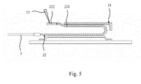
Fig.5 is a section view of the snap-fitted receptacle and plug according to the present invention. - In the drawings:
- 1. strip lamp; 11. light-emitting diode; 21. receptacle; 211. bayonet; 22. plug; 221. elastic piece; 222. buckling portion; 23. pressing
pin 3. wire; 4. backplate; 41. outlet - Detailed description of the embodiment of present invention is provided in the following description, and examples of the embodiments are shown in the drawings. Throughout this disclosure, identical or similar reference numerals refer to identical or similar elements or elements having identical or similar functions. The embodiments described below by reference to the drawings are illustrative, and are only used to illustrate the present invention without limiting.
- Unless defined otherwise, the technical terms or scientific terminology used herein should be construed as the meaning usually understood by those skilled in this art of present invention. In the description of the present invention, it should be understood that the orientation or position relationship illustrated by the terminology "center", "longitudinal", "transverse", "upper", "lower", "front", "rear", "left", "right", "vertical", "horizontal", "top", "bottom", "inner", "outer" and the like refer to the orientation or position relationship illustrated based on the drawings, and are used for illustrating the present invention and simplifying the description, rather than teaching or suggesting that the denoted devices or components have to be in specific orientation, and be constructed and operated in specific orientation. Accordingly they are not intended to limitation to the present invention. Furthermore, the terminologies "first" and "second" are used only for the purpose of illustration, and cannot be considered as limitation.
- The embodiments of present invention provide a direct type backlight module, as shown in
Fig.1 , comprising abackplate 4, and a plurality ofstrip lamps 1 provided on thebackplate 4, each of thestrip lamps 1 is provided with a lamp set composed of a plurality of light-emitting diodes 11. The direct type backlight module further comprising: - a plurality of
wires 3 via which the lamp sets of the plurality of strip lamps are connected to the power supply. - The lamp set of each
strip lamp 1 comprises two terminals, i.e., positive/negative terminals, as shown inFig.2 . The positive terminal of the lamp set is electrically connected to acorresponding wire 3 via a pair of snap-fittedplug 22 andreceptacle 21. The negative terminal of the lamp set is electrically connected to acorresponding wire 3 in a similar way as mentioned above. - With the direct type backlight module provided by the embodiment of present invention, when assembling the strip lamps, a serial or parallel connection between each of the plurality of
strip lamps 1 can be achieved by using thewires 3 as well as each pair of snap-fittedplug 22 and thereceptacle 21. - With the direct type backlight module provided by the embodiment of present invention, when assembling the strip lamps, the situation mentioned in the Background, where the serial or parallel connection between each of the plurality of strip lamps is achieved by directly welding the strip lamps to the printed circuit board, can be eliminated.
- Accordingly, the present invention provides a direct type backlight module that facilitates an easier mounting and individual replacement of a single strip lamp.
- In the aforesaid preferred embodiments, the positive/negative terminals of the lamp set are electrically connected to
corresponding wires 3 via a pair of snap-fittedplug 22 andreceptacle 21. However, the present invention is not limited thereto. In alternate embodiments, the positive/negative terminals of the lamp set may be electrically connected to thecorresponding wires 3 via a pair of male connector and female connector removably mated with each other. In other alternate embodiments, the positive/negative terminals of the lamp set may be electrically connected to thecorresponding wires 3 by a pair of any suitable connectors removably mated with each other. - In some optional embodiments, the lamp set of at least one
strip lamp 1 of the plurality ofstrip lamps 1 is electrically connected to the power supply via the plurality of wires, and the lamp set of the at least onestrip lamp 1 has two terminals, i.e., the positive/negative terminals, the positive/negative terminals of the lamp set of the at least onestrip lamp 1 are electrically connected to the corresponding wires in the above mentioned manner. - In other optional embodiments, the lamp sets of all the
strip lamps 1 are electrically connected to the power supply via the plurality of wires, and each of the lamp sets of all thestrip lamp 1 has two terminals, i.e., positive/negative terminals, all the positive/negative terminals of the lamp set of all thestrip lamps 1 are electrically connected to corresponding wires in the above mentioned manner. - In alternate embodiments, as shown in
Fig.3 , thereceptacle 21 of each pair of theaforesaid plug 22 and thereceptacle 21 is provided with abayonet 211. As shown inFig.4 , the side of theplug 22 facing thebayonet 211 is provided with anelastic piece 221, with one end of theelastic piece 221 being provided with a bucklingportion 222 for snap-fitting into thebayonet 211. During the process of inserting theplug 22 into thereceptacle 21, theelastic piece 221 on theplug 21 will be compressively deformed toward the side away from thebayonet 211, and theelastic piece 221 rebounds when the bucklingportion 222 is located below thebayonet 211, such that the bucklingportion 222 is snap-fitted into thebayonet 211. Such a configuration achieves the snap-fit between theplug 22 and thereceptacle 21. - To facilitate the inserting of the
plug 22 into thereceptacle 21, the above mentionedbayonet 211 is preferably arranged at the side of thereceptacle 21 away from thestrip lamp 1. - To facilitate the serial or parallel connection between the
strip lamps 1, preferably in eachstrip lamp 1, thereceptacle 21 corresponding to the positive terminal of the lamp set is provided at one end of thestrip lamp 1, and thereceptacle 21 corresponding to the negative terminal of the lamp set is provided at the other end of thestrip lamp 1, as shown inFig.1 . - As shown in
Fig.1 , thebackplate 4 is further provided with anoutlet 41, through which thewire 3 is electrically connected to the power supply. Thewire 3 connecting eachstrip lamp 1 in a serial or parallel manner electrically connects to the power supply through theoutlet 41. - Each
receptacle 21 can be secured onto eachstrip lamp 1 in various manners: - Each of the
receptacles 21 is welded onto acorresponding strip lamp 1. Welding of thereceptacle 21 can prevent the occurrence of a poor contact. When replacing thestrip lamp 1, first removing the correspondingplug 22 from thereceptacle 21, then replacing the usedstrip lamp 1 welded with areceptacle 21 with anew strip lamp 1 welded with areceptacle 21, and finally snap-fitting thecorresponding plug 22 into thereceptacle 21 of thenew strip lamp 1. - Each
receptacle 21 is removably mounted to acorresponding strip lamp 1. Thereceptacle 21 can be mounted to itscorresponding strip lamp 1 by a snap-fitting, or other appropriate manners, with the detail description thereof omitted herein. Theremovable receptacle 21 allows thestrip lamp 1 which does not work properly to be replaced individually, and thus the cost can be reduced. - As shown in
Fig.5 , to facilitate the removal of theplug 22 from thereceptacle 21, the present invention is also provided with apressing pin 23 for pressing the bucklingportion 222. When it is desired to remove theplug 22 from thereceptacle 21, thepressing pin 23 may press down the bucklingportion 222 of theplug 22, and then theelastic piece 221 will compressively deform toward the side away from thebayonet 211, thereby the bucklingportion 222 is moved out of thebayonet 211 so as to facilitate the removal of theplug 22 from thereceptacle 21. - In the above mentioned manners, the
plug 22 and thereceptacle 21 can be made from plastics, or metal materials, as well as other appropriate materials; the detailed description is omitted here. - The embodiment of present invention provides a display device comprising a display panel and the above mentioned direct type backlight module.
- In the display device comprising the above mentioned direct type backlight module according to the embodiment of present invention, during the assemble process, a serial or parallel connection between the
strip lamps 1 can be achieved by means of snap-fitting between theplug 22 and thereceptacle 21 when mounting thestrip lamp 1, thereby manpower and man-hour can be reduced. Accordingly, the present invention provides a display device with higher production efficiency. - The above descriptions are only exemplary embodiments for illustrating the principle of the present invention, and are not intended to limit the protective scope of the present invention. Obviously, various alternations and modifications can be made by those skilled in this art, without departing from the spirit and essence of the present invention. Such alternations and modifications are also within the protective scope of this invention.
Claims (11)
- A direct type backlight module, comprising a backplate (4) and a plurality of strip lamps (1) provided on the backplate (4), each of the plurality of strip lamps (1) being provided with a lamp set composed of a plurality of LEDs (11), characterized in that
the direct type backlight module further comprises a plurality of wires (3), and the lamp set of at least one strip lamp (1) of the plurality of strip lamps (1) is electrically connected to the power supply via the plurality of wires (3);
the lamp set of the at least one strip lamp (1) has two terminals, i.e., the positive/negative terminals, the positive/negative terminals of the lamp set of the at least one strip lamp (1) are electrically connected to its corresponding wire (3) via a pair of mated connectors. - The direct type backlight module according to claim 1, characterized in that the pair of mated connectors is a pair of male connector and female connector removably mated with each other.
- The direct type backlight module according to claim 1, characterized in that the pair of mated connectors is a pair of snap-fitted plug (22) and receptacle (21).
- The direct type backlight module according to claim 1, characterized in that the lamp set of each of the plurality of strip lamps (1) is connected to the power supply via the plurality of wires (3); the lamp set of each of the plurality of strip lamps (1) have two terminals, i.e., positive/negative terminals, the positive/negative terminals of the lamp set of each of the plurality of strip lamp (1) is electrically connected with the corresponding wires (3) via a pair of snap-fitted plug (22) and receptacle (21).
- The direct type backlight module according to any one of claims 1-4, characterized in that the receptacle (21) in each pair of plug (22) and receptacle (21) is provided with a bayonet (211); the side of the plug (22) facing the bayonet (211) is provided with an elastic piece (221), and the elastic piece (221) is provided at one end with a buckling portion (222) for snap-fitting into the bayonet (211).
- The direct type backlight module according to claim 5, characterized in that the bayonet (211) is provided at the side of the receptacle (21) away from the strip lamp (1).
- The direct type backlight module according to any one claims 1- 4, characterized in that in each of the strip lamp (1), the receptacle (21) corresponding to the positive terminal of the lamp set is provided at one end of the strip lamp (1), and the receptacle (21) corresponding to the negative terminal of the lamp set is provided at the other end of the strip lamp (1).
- The direct type backlight module according to any one of claims 1-7, characterized in that the wires (3) are electrically connected to the power supply through an outlet (41) provided on the backplate (4).
- The direct type backlight module according to claim 4, characterized in that each of the receptacles (21) is welded to its corresponding strip lamp (1).
- The direct type backlight module according to claim 4, characterized in that each of the receptacles (21) is removably mounted to its corresponding strip lamp (1).
- A display device comprising a display panel, characterized in that the display device further comprises the direct type backlight module according to any one of claims 1-10.
Applications Claiming Priority (1)
| Application Number | Priority Date | Filing Date | Title |
|---|---|---|---|
| CN201310031382.XA CN103090273B (en) | 2013-01-28 | 2013-01-28 | Straight down type backlight module and display device provided with the same |
Publications (2)
| Publication Number | Publication Date |
|---|---|
| EP2759870A2 true EP2759870A2 (en) | 2014-07-30 |
| EP2759870A3 EP2759870A3 (en) | 2014-10-15 |
Family
ID=48203194
Family Applications (1)
| Application Number | Title | Priority Date | Filing Date |
|---|---|---|---|
| EP14150565.1A Ceased EP2759870A3 (en) | 2013-01-28 | 2014-01-09 | Direct type backlight module and display device |
Country Status (3)
| Country | Link |
|---|---|
| US (1) | US9695994B2 (en) |
| EP (1) | EP2759870A3 (en) |
| CN (1) | CN103090273B (en) |
Families Citing this family (6)
| Publication number | Priority date | Publication date | Assignee | Title |
|---|---|---|---|---|
| CN103322534A (en) * | 2013-06-21 | 2013-09-25 | 深圳市华星光电技术有限公司 | Direct-light-type backlight module lamp strip assembly structure, assembly method and liquid crystal display |
| CN106782161B (en) * | 2017-02-08 | 2019-08-16 | 京东方科技集团股份有限公司 | A light source component, a transparent display module and a transparent display device |
| JP7065355B2 (en) * | 2017-02-09 | 2022-05-12 | パナソニックIpマネジメント株式会社 | Image display device |
| EP3581996B1 (en) * | 2017-02-09 | 2021-04-14 | Panasonic Intellectual Property Management Co., Ltd. | Image display device |
| CN115113436B (en) * | 2022-06-20 | 2023-07-07 | 深圳市群宇科技有限公司 | High-production-efficiency separated backlight module |
| CN116772131B (en) * | 2023-06-26 | 2024-08-23 | 惠科股份有限公司 | Lamp panel, manufacturing method of lamp panel and display device |
Citations (1)
| Publication number | Priority date | Publication date | Assignee | Title |
|---|---|---|---|---|
| US20080305668A1 (en) * | 2007-06-11 | 2008-12-11 | Hon Hai Precision Ind. Co., Ltd. | Cable connector assembly for solar device |
Family Cites Families (9)
| Publication number | Priority date | Publication date | Assignee | Title |
|---|---|---|---|---|
| TWI274209B (en) * | 2004-07-16 | 2007-02-21 | Chi Lin Technology Co Ltd | Light emitting diode and backlight module having light emitting diode |
| KR20090131175A (en) * | 2008-06-17 | 2009-12-28 | 삼성전자주식회사 | Backlight unit for liquid crystal display device |
| CN102042532A (en) * | 2009-10-15 | 2011-05-04 | 瀚宇彩晶股份有限公司 | Light-emitting unit, backlight module and display device |
| WO2011148733A1 (en) | 2010-05-26 | 2011-12-01 | シャープ株式会社 | Lighting device, display device, and television receiving device |
| CN201731392U (en) * | 2010-08-13 | 2011-02-02 | 福建华映显示科技有限公司 | Backlight module |
| WO2012128074A1 (en) | 2011-03-18 | 2012-09-27 | シャープ株式会社 | Illumination device, display device, and television reception device |
| JP4885320B1 (en) * | 2011-03-23 | 2012-02-29 | 日本航空電子工業株式会社 | Wire-to-board connector |
| CN202691759U (en) * | 2012-04-06 | 2013-01-23 | 华映视讯(吴江)有限公司 | Display and backlight module thereof |
| CN202647639U (en) * | 2012-04-27 | 2013-01-02 | 青岛海信电器股份有限公司 | Lamp bar connecting structure and backlight module |
-
2013
- 2013-01-28 CN CN201310031382.XA patent/CN103090273B/en active Active
- 2013-12-18 US US14/132,778 patent/US9695994B2/en active Active
-
2014
- 2014-01-09 EP EP14150565.1A patent/EP2759870A3/en not_active Ceased
Patent Citations (1)
| Publication number | Priority date | Publication date | Assignee | Title |
|---|---|---|---|---|
| US20080305668A1 (en) * | 2007-06-11 | 2008-12-11 | Hon Hai Precision Ind. Co., Ltd. | Cable connector assembly for solar device |
Also Published As
| Publication number | Publication date |
|---|---|
| US20140211452A1 (en) | 2014-07-31 |
| CN103090273B (en) | 2015-01-07 |
| EP2759870A3 (en) | 2014-10-15 |
| US9695994B2 (en) | 2017-07-04 |
| CN103090273A (en) | 2013-05-08 |
Similar Documents
| Publication | Publication Date | Title |
|---|---|---|
| US9695994B2 (en) | Direct type backlight module and display device | |
| CN104993310A (en) | Wie Wiring terminal branched connector | |
| CN103939859A (en) | How to assemble LED lights | |
| EP3273157A1 (en) | Led lamp electrical connection member | |
| CN201927740U (en) | Light tube connector | |
| CN104180255A (en) | Lamp bar assembly, backlight module and liquid crystal display | |
| CN203477986U (en) | LED backlight module group | |
| WO2014201720A1 (en) | Direct-lit backlight module light strip assembly structure, assembly method, and liquid crystal display | |
| CN201601359U (en) | Adaptor of high-voltage line connector of backlight module | |
| CN203871509U (en) | Electric connector and LED lamp bar using same | |
| CN204786263U (en) | Spotlight electrical connection structure | |
| CN203326291U (en) | Electric connector | |
| CN212304128U (en) | Electric connector and backlight module | |
| CN201000988Y (en) | Socket connector | |
| CN104406067A (en) | Simply assembled splicing type LED lamp tube | |
| CN203660105U (en) | Plug-in type lamp cap in which driver is provided, and LED fluorescent lamp having the same | |
| CN217589480U (en) | Electric connector, backlight module and display device | |
| CN201741864U (en) | Two-core socket | |
| CN206207358U (en) | Electrical connectors and LED lighting devices | |
| CN208818990U (en) | A light bar and backplane | |
| CN205488696U (en) | LED lamp connector | |
| CN201547696U (en) | Connector | |
| CN102620258B (en) | LED (light emitting diode) strip quick connecting structure | |
| CN217955376U (en) | Hard connecting structure of LED display screen module | |
| CN213987112U (en) | Straight following formula liquid crystal display backlight lamp strip structure |
Legal Events
| Date | Code | Title | Description |
|---|---|---|---|
| PUAI | Public reference made under article 153(3) epc to a published international application that has entered the european phase |
Free format text: ORIGINAL CODE: 0009012 |
|
| 17P | Request for examination filed |
Effective date: 20140109 |
|
| AK | Designated contracting states |
Kind code of ref document: A2 Designated state(s): AL AT BE BG CH CY CZ DE DK EE ES FI FR GB GR HR HU IE IS IT LI LT LU LV MC MK MT NL NO PL PT RO RS SE SI SK SM TR |
|
| AX | Request for extension of the european patent |
Extension state: BA ME |
|
| PUAL | Search report despatched |
Free format text: ORIGINAL CODE: 0009013 |
|
| AK | Designated contracting states |
Kind code of ref document: A3 Designated state(s): AL AT BE BG CH CY CZ DE DK EE ES FI FR GB GR HR HU IE IS IT LI LT LU LV MC MK MT NL NO PL PT RO RS SE SI SK SM TR |
|
| AX | Request for extension of the european patent |
Extension state: BA ME |
|
| RIC1 | Information provided on ipc code assigned before grant |
Ipc: G02F 1/13357 20060101AFI20140909BHEP Ipc: H01R 12/75 20110101ALI20140909BHEP Ipc: H01R 13/20 20060101ALI20140909BHEP Ipc: H01R 12/70 20110101ALI20140909BHEP |
|
| R17P | Request for examination filed (corrected) |
Effective date: 20150413 |
|
| RBV | Designated contracting states (corrected) |
Designated state(s): AL AT BE BG CH CY CZ DE DK EE ES FI FR GB GR HR HU IE IS IT LI LT LU LV MC MK MT NL NO PL PT RO RS SE SI SK SM TR |
|
| 17Q | First examination report despatched |
Effective date: 20151214 |
|
| STAA | Information on the status of an ep patent application or granted ep patent |
Free format text: STATUS: THE APPLICATION HAS BEEN REFUSED |
|
| 18R | Application refused |
Effective date: 20170313 |