EP2759863A1 - Head mounted image display device - Google Patents
Head mounted image display device Download PDFInfo
- Publication number
- EP2759863A1 EP2759863A1 EP14152627.7A EP14152627A EP2759863A1 EP 2759863 A1 EP2759863 A1 EP 2759863A1 EP 14152627 A EP14152627 A EP 14152627A EP 2759863 A1 EP2759863 A1 EP 2759863A1
- Authority
- EP
- European Patent Office
- Prior art keywords
- laser light
- light
- notification
- image drawing
- optical fiber
- Prior art date
- Legal status (The legal status is an assumption and is not a legal conclusion. Google has not performed a legal analysis and makes no representation as to the accuracy of the status listed.)
- Withdrawn
Links
- 239000013307 optical fiber Substances 0.000 claims description 174
- 238000003384 imaging method Methods 0.000 claims description 80
- 230000008859 change Effects 0.000 claims description 7
- 239000003086 colorant Substances 0.000 claims description 3
- 210000003128 head Anatomy 0.000 description 35
- 230000003287 optical effect Effects 0.000 description 34
- 239000010408 film Substances 0.000 description 10
- 230000002238 attenuated effect Effects 0.000 description 9
- 239000000463 material Substances 0.000 description 8
- 230000008878 coupling Effects 0.000 description 7
- 238000010168 coupling process Methods 0.000 description 7
- 238000005859 coupling reaction Methods 0.000 description 7
- 230000005236 sound signal Effects 0.000 description 7
- 239000000758 substrate Substances 0.000 description 7
- 238000010586 diagram Methods 0.000 description 6
- 238000000034 method Methods 0.000 description 6
- 230000000694 effects Effects 0.000 description 5
- 210000000887 face Anatomy 0.000 description 4
- 239000000049 pigment Substances 0.000 description 4
- 230000004044 response Effects 0.000 description 4
- 230000006870 function Effects 0.000 description 3
- GWEVSGVZZGPLCZ-UHFFFAOYSA-N Titan oxide Chemical compound O=[Ti]=O GWEVSGVZZGPLCZ-UHFFFAOYSA-N 0.000 description 2
- XLOMVQKBTHCTTD-UHFFFAOYSA-N Zinc monoxide Chemical compound [Zn]=O XLOMVQKBTHCTTD-UHFFFAOYSA-N 0.000 description 2
- 230000007423 decrease Effects 0.000 description 2
- 210000005069 ears Anatomy 0.000 description 2
- RYZCLUQMCYZBJQ-UHFFFAOYSA-H lead(2+);dicarbonate;dihydroxide Chemical compound [OH-].[OH-].[Pb+2].[Pb+2].[Pb+2].[O-]C([O-])=O.[O-]C([O-])=O RYZCLUQMCYZBJQ-UHFFFAOYSA-H 0.000 description 2
- 230000007935 neutral effect Effects 0.000 description 2
- 239000002245 particle Substances 0.000 description 2
- 230000008569 process Effects 0.000 description 2
- 230000035807 sensation Effects 0.000 description 2
- 235000010215 titanium dioxide Nutrition 0.000 description 2
- 235000014692 zinc oxide Nutrition 0.000 description 2
- 239000011787 zinc oxide Substances 0.000 description 2
- 230000009471 action Effects 0.000 description 1
- 230000004913 activation Effects 0.000 description 1
- 239000000853 adhesive Substances 0.000 description 1
- 230000001070 adhesive effect Effects 0.000 description 1
- 230000008901 benefit Effects 0.000 description 1
- 239000012141 concentrate Substances 0.000 description 1
- 230000009849 deactivation Effects 0.000 description 1
- 210000001061 forehead Anatomy 0.000 description 1
- 239000011521 glass Substances 0.000 description 1
- 229910052751 metal Inorganic materials 0.000 description 1
- 239000002184 metal Substances 0.000 description 1
- 239000002923 metal particle Substances 0.000 description 1
- 230000004048 modification Effects 0.000 description 1
- 238000012986 modification Methods 0.000 description 1
- 239000011347 resin Substances 0.000 description 1
- 229920005989 resin Polymers 0.000 description 1
- 239000010409 thin film Substances 0.000 description 1
- 230000032258 transport Effects 0.000 description 1
Images



Classifications
-
- G—PHYSICS
- G02—OPTICS
- G02B—OPTICAL ELEMENTS, SYSTEMS OR APPARATUS
- G02B27/00—Optical systems or apparatus not provided for by any of the groups G02B1/00 - G02B26/00, G02B30/00
- G02B27/01—Head-up displays
- G02B27/017—Head mounted
- G02B27/0172—Head mounted characterised by optical features
-
- G—PHYSICS
- G02—OPTICS
- G02B—OPTICAL ELEMENTS, SYSTEMS OR APPARATUS
- G02B26/00—Optical devices or arrangements for the control of light using movable or deformable optical elements
- G02B26/08—Optical devices or arrangements for the control of light using movable or deformable optical elements for controlling the direction of light
- G02B26/0816—Optical devices or arrangements for the control of light using movable or deformable optical elements for controlling the direction of light by means of one or more reflecting elements
-
- H—ELECTRICITY
- H04—ELECTRIC COMMUNICATION TECHNIQUE
- H04N—PICTORIAL COMMUNICATION, e.g. TELEVISION
- H04N13/00—Stereoscopic video systems; Multi-view video systems; Details thereof
- H04N13/30—Image reproducers
- H04N13/332—Displays for viewing with the aid of special glasses or head-mounted displays [HMD]
- H04N13/339—Displays for viewing with the aid of special glasses or head-mounted displays [HMD] using spatial multiplexing
-
- G—PHYSICS
- G02—OPTICS
- G02B—OPTICAL ELEMENTS, SYSTEMS OR APPARATUS
- G02B27/00—Optical systems or apparatus not provided for by any of the groups G02B1/00 - G02B26/00, G02B30/00
- G02B27/01—Head-up displays
- G02B27/017—Head mounted
- G02B2027/0178—Eyeglass type
-
- G—PHYSICS
- G02—OPTICS
- G02B—OPTICAL ELEMENTS, SYSTEMS OR APPARATUS
- G02B27/00—Optical systems or apparatus not provided for by any of the groups G02B1/00 - G02B26/00, G02B30/00
- G02B27/01—Head-up displays
- G02B27/0179—Display position adjusting means not related to the information to be displayed
- G02B2027/0187—Display position adjusting means not related to the information to be displayed slaved to motion of at least a part of the body of the user, e.g. head, eye
Definitions
- the present invention relates to an image display apparatus.
- JP-A-2009-86365 discloses one form of such an image display apparatus.
- JP-A-2009-86365 describes that the minimum brightness of a projected display image is lowered to improve the contrast ratio of the projected display image by causing light to pass through an ND filter (neutral density) or shifting the optical axis of an optical fiber.
- ND filter neutral density
- An advantage of some aspects of the invention is to provide an image display apparatus that allows efficient use of light.
- This application example is directed to an image display apparatus mounted around on head of a person, the apparatus including a light source that emits laser light, a splitter that splits the laser light into first laser light and second laser light having a different power than the first laser light, an image drawing section that causes the first laser light to be reflected off a mirror and causes the mirror to make pivotal motion to perform image drawing, a controller that controls the pivotal motion of the mirror, and a notification section that notifies other persons by diffusing the second laser light that the image drawing section is performing image drawing with.
- the light source emits laser light toward the splitter.
- the splitter splits the laser light into the first laser light and the second laser light.
- the split laser light beams travel as follows: the first laser light impinges on the image drawing section; and the second laser light impinges on the notification section.
- the image drawing section includes a mirror, and the first laser light impinges on the mirror.
- the controller controls pivotal motion of the mirror to change the direction in which the first laser light travels for image drawing.
- the notification section diffuses the second laser light to notify (e.g., make readily apparent, alert or broadcast) that the image drawing is underway.
- the light source emits no laser light, and no second laser light is therefore diffused. As a result, whether or not the image display apparatus is performing image drawing can be notified.
- the image display apparatus uses the laser light emitted from the light source both in the image drawing and notification operation, whereby the laser light can be efficiently used.
- This application example is directed to the image display apparatus according to the application example described above, wherein the power of the first laser light is lower than the power of the second laser light.
- the laser light is split so that the power of the first laser light is lower than the power of the second laser light.
- the power of the first laser light is unstable.
- the light source is therefore operated to emit laser light the amount of which is large enough to ensure stable light emission operation.
- the split first laser light has a high power
- the first laser light having undergone image drawing operation may damage the eyes.
- the power of the second laser light is set to be higher than the power of the first laser light. Therefore, even when the light source emits laser light having a high power, the first laser light has a low power and image drawing can be performed by using the first laser light having a safe power.
- This application example is directed to the image display apparatus according to the application example described above, wherein the splitter splits the laser light into the first laser light and the second laser light using a reflection film that transmits part of the laser light.
- the splitter includes a reflection film.
- a reflection film reflects a greater amount of light when the thickness thereof is greater, whereas transmitting a greater amount of light when the thickness thereof is smaller.
- the splitter can therefore readily adjust the optical intensities of the first laser light and the second laser light.
- This application example is directed to the image display apparatus according to the application example described above, wherein the laser light is formed of a plurality of light rays having different colors, and the splitter combines the plurality of light rays with each other and separates the plurality of light rays from each other.
- the light source emits laser light formed of a plurality of light rays.
- the image drawing section can therefore perform image drawing with a large number of color light beams.
- the splitter combines the light beams with each other and separates the light beams from each other simultaneously.
- the image display apparatus can therefore be readily manufactured because the apparatus is simplified as compared with a case where an optical system that combines the light beams with each other and an optical system that separates the light beams from each other are separate optical systems.
- This application example is directed to the image display apparatus according to the application example described above, wherein the second laser light is red laser light.
- the second laser light is red laser light
- the notification section diffuses the red light. Red light is more noticeable than blue light and green light.
- the notification section can therefore noticeably notify that image drawing is underway.
- This application example is directed to the image display apparatus according to the application example described above, wherein the laser light is guided through a light-source optical fiber, the first laser light is guided through a first optical fiber, and the second laser light is guided through a second optical fiber, and in the splitter, an end surface of the light-source optical fiber is connected to an end surface of the first optical fiber and an end surface of the second optical fiber, and the area of the end surface of the first optical fiber where the end surface of the first optical fiber is connected to the end surface of the light-source optical fiber is narrower than the area of the end surface of the second optical fiber where the end surface of the second optical fiber is connected to the end surface of the light-source optical fiber.
- part of the laser light having exited out of the light-source optical fiber is incident on the first optical fiber, and part of the laser light is incident on the second optical fiber.
- the light incident area of the end surface of the first optical fiber is narrower than the light incident area of the end surface of the second optical fiber.
- the power of the first laser light incident on the first optical fiber can therefore be lower than the power of the second laser light incident on the second optical fiber.
- This application example is directed to the image display apparatus according to the application example described above, wherein the image display apparatus further includes an imaging section, and the notification section diffuses the second laser light to notify that the imaging section is performing imaging.
- the notification section uses the second laser light to notify whether or not the imaging section is performing imaging. Using no second laser light requires a notification light source.
- the image display apparatus can therefore be readily manufactured because the apparatus can be simplified as compared with a case where a light source for notifying whether the imaging section is performing imaging is provided.
- This application example is directed to the image display apparatus according to the application example described above, wherein the image display apparatus further includes a light attenuator that attenuates the power of the second laser light.
- the light attenuator adjusts the power of the second laser light.
- the light attenuator can therefore prevent the light diffused by the notification section from being too glaring.
- This application example is directed to the image display apparatus according to the application example described above, wherein the light attenuator attenuates the second laser light in accordance with the power of the second laser light to suppress change in the power of the second laser light diffused by the notification section.
- the light attenuator attenuates the second laser light when the power thereof is high to prevent change in the power of the second laser light diffused by the notification section.
- the light attenuator therefore allows the light diffused by the notification section to have a readily recognizable power.
- This application example is directed to the image display apparatus according to the application example described above, wherein the image display apparatus further includes a support that supports the image drawing section with the aid of the head of the person, and the notification section is disposed on the support in a position visible from the front and lateral sides of the head of the person.
- the notification section is disposed on the support, and a person who looks at the head of the person from the front can check the notification section. Further, a person who looks at the head of the person from either of the lateral sides can also check the notification section.
- the notification section can therefore issue notification forward and sideways with respect to the person to notify that the image display apparatus is performing image drawing.
- This application example is directed to the image display apparatus according to the application example described above, wherein the notification section is disposed on the support in a position visible from the lateral side on the right and the lateral side on the left when viewed from the front of the head of the person.
- the notification section is visible from both right and left sides of the head of the person viewed from the front. Since the notification section can therefore readily be recognized from both sides of the person, the notification section can issue notification within a wide angular range to notify that the image display apparatus is performing image drawing.
- This application example is directed to an image display apparatus mounted on the head of a person, the apparatus including a light source that emits laser light, a splitter that splits the laser light into first laser light and second laser light different from the first laser light in terms of power, an image drawing section that performs image drawing by using the first laser light, and a notification section that notifies other persons by using the second laser light that the image drawing section is performing image drawing.
- the light source emits laser light toward the splitter.
- the splitter splits the laser light into the first laser light and the second laser light.
- the split laser light beams travel as follows: The first laser light impinges on the image drawing section; and the second laser light impinges on the notification section.
- the image drawing section performs image drawing by using the first laser light.
- the notification section diffuses the second laser light to notify that the image drawing is underway.
- the light source emits no laser light, and no second laser light is therefore diffused. As a result, whether or not the image display apparatus is performing image drawing can be notified.
- the image display apparatus uses the laser light emitted from the light source both in the image drawing and notification operation, whereby the laser light can be efficiently used.
- This application example is directed to the image display apparatus according to the application example described above, wherein the power of the first laser light is lower than the power of the second laser light.
- the laser light is split so that the power of the first laser light is lower than the power of the second laser light.
- the power of the first laser light is unstable.
- the light source is therefore operated to emit laser light the amount of which is large enough to ensure stable light emission operation.
- the split first laser light has a high power
- the first laser light having undergone image drawing operation may damage the eyes.
- the power of the second laser light is set to be higher than the power of the first laser light. Therefore, even when the light source emits laser light having a high power, the first laser light has a low power and image drawing can be performed by using the first laser light having a safe power.
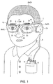
- Fig. 1 is a schematic perspective view showing the structure of the image display apparatus.
- the image display apparatus 1 is mounted on a head 2a of a viewer 2, as shown in Fig. 1 .
- the image display apparatus 1 includes a base portion 3 as a support having a shape similar to the frame of glasses.
- the base portion 3 includes sidepieces 3a and a frame 3b.
- the sidepieces 3a When the image display apparatus is mounted on the head 2a, the sidepieces 3a are located on the lateral sides of the head 2a and sandwiched between the head 2a and ears 2b of the viewer 2.
- the sidepieces 3a are attached to both ends of the base portion 3 and located on the right and left sides of the head 2a.
- the frame 3b is disposed between the two sidepieces 3a.
- the frame 3b When the image display apparatus is mounted on the head 2a, the frame 3b is located in front of the head 2a in a position facing eyes 2c of the viewer 2.
- a hinge is provided between the frame 3b and each of the sidepiece 3a. The hinges allow the sidepieces 3a to be folded relative to the frame 3b.
- a pair of nose pads 4 are attached to the frame 3b and come into contact with a nose 2d of the viewer 2.
- the nose pads 4 and the sidepieces 3a come into contact with the head 2a, and the base portion 3 is supported with the aid of the nose pads 4 and the sidepieces 3a.
- a cable 5 is connected to one of the sidepieces 3a, and a display control unit 6 is connected to the cable 5.
- the cable 5 has an electric wiring line and an optical fiber built therein.
- the display control unit 6 is connected to a video recording/reproducing apparatus 8 via a cable 7.
- the base portion 3 is provided with scanning optical output sections 9 as a pair of image drawing sections above the nose pads 4 in Fig. 1 , and half-silvered mirrors 10 are disposed as the pair of image drawing sections in positions facing the eyes 2c.
- the base portion 3 is further provided with an imaging section 11 in a position between the pair of scanning optical output sections 9, and the imaging section 11 has a microphone 11a built therein.
- An image drawing notification section 12 is provided as a notification section having a circular columnar shape on the base portion 3 on the upper side in Fig. 1 in the vicinity of a portion where the frame 3b and each of the sidepiece 3a are connected to each other.
- the image drawing notification sections 12 are disposed on the base portion 3 in positions visible from the front and lateral sides of the head 2a. In other words, the image drawing notification sections 12 are disposed on the base portion 3, when viewed from the front of the head 2a, in a position visible from the right side and in a position visible from the left side.
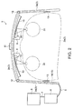
- Fig. 2 is a diagrammatic plan view showing the structure of the image display apparatus.
- a loudspeaker 13 is provided between the head 2a and each of the sidepieces 3a, as shown in Fig. 2 .
- the loudspeaker 13 is preferably a bone-conduction loudspeaker.
- An electric wiring line 14 and an optical fiber 15, which are extensions of those in the cable 5, are provided inside the sidepieces 3a and the frame 3b.
- the scanning optical output sections 9, the bone-conduction loudspeakers 13, and the imaging section 11 are connected to the electric wiring line 14 and driven by the display control unit 6.
- the scanning optical output sections 9 and the image drawing notification sections 12 are connected to the optical fiber 15 and receives laser light 16 from the display control unit 6.
- the scanning optical output sections 9 continuously deflect the laser light 16 in upward, downward, rightward, and leftward directions and output the resultant light toward the half-silvered mirrors 10.
- the outputted laser light is reflected off the half-silvered mirrors 10 and travels toward the eyes 2c of the viewer 2.
- the viewer 2 observes a virtual image formed by the image display apparatus 1.
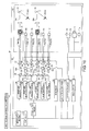
- Fig. 3 is an electrical control block diagram showing the structure of the image display apparatus.
- the display control unit 6 provided in the image display apparatus 1 accommodates an input/output section 17, and the video recording/reproducing apparatus 8 is connected to the input/output section 17, as shown in Fig. 3 .
- the video recording/reproducing apparatus 8 includes a storage section, which stores video image data, still image data, and audio data.
- the video recording/reproducing apparatus 8 outputs the video image data and the still image data to the input/output section 17.
- the video recording/reproducing apparatus 8 receives the video image data, the still image data, and the audio data as inputs and stores them in the storage section.
- the input/output section 17 is provided with a connector, a switch, and a variable resistor (not shown).
- the cable 7 is connected to the connector.
- the switch is disposed at a plurality of locations for power on/off operation of the image display apparatus 1, activation and deactivation of audio output, and other purposes.
- the variable resistor is disposed at a plurality of locations for adjustment of brightness of video images, adjustment of luminance of light through the image drawing notification sections 12, adjustment of volume of sound from the bone-conduction loudspeakers 13, and other purposes.
- a controller 20 is connected to the input/output section 17.
- a light source driver 21, a scan driver 22, a light attenuation driver 23, a loudspeaker driver 24, an imaging driver 25, and other components are connected to the controller 20, and the controller 20 controls action of each of the components.
- the controller 20 controls action of each of the components.
- the controller 20 outputs a luminance signal associated with video images and a luminance adjustment signal inputted to the corresponding variable resistor to the light source driver 21.
- the controller 20 outputs a scan signal associated with the video images to the scan driver 22.
- the controller 20 outputs a red luminance signal that is part of the video signal to the light attenuation driver 23.
- a right-side green light source 26, a right-side blue light source 27, a right-side red light source 28, a left-side green light source 29, a left-side blue light source 30, and a left-side red light source 31 are connected to the light source driver 21.
- the right-side green light source 26, the right-side blue light source 27, and the right-side red light source 28 supply the laser light 16 to the scanning optical output section 9 that outputs the laser light 16 to the right eye 2e.
- the left-side green light source 29, the left-side blue light source 30, and the left-side red light source 31 supply the laser light 16 to the scanning optical output section 9 that outputs the laser light 16 to the left eye 2f.
- the video signal When the video signal is a signal for a stereoscopic image, the video signal has a right-eye video signal to be observed with the right eye 2e and a left-eye video signal to be observed with the left eye 2f.
- the video signal is a signal for a color image, each of the right-eye and left-eye video signals has a green signal, a blue signal, and a red signal.
- the light source driver 21 outputs electric power according to the video signal to each of the right-side green light source 26 to the left-side red light source 31.
- electric power according to the green signal of the right-eye video signal is outputted to the right-side green light source 26, and electric power according to the blue signal of the right-eye video signal is outputted to the right-side blue light source 27.
- electric power according to the red signal of the right-eye video signal is outputted to the right-side red light source 28.
- electric power according to the green signal of the left-eye video signal is outputted to the left-side green light source 29, and electric power according to the blue signal of the left-eye video signal is outputted to the left-side blue light source 30.
- electric power according to the red signal of the left-eye video signal is outputted to the left-side red light source 31.
- Each of the right-side green light source 26 and the right-side blue light source 27 has an ND (neutral density) filter built therein.
- the attenuation factor of the ND filter is not limited to a specific value, but laser light 16 having a magnitude of about 1/10000 of the amount of laser light emitted from the light source is outputted through the ND filter in the present embodiment.
- the light emitted from the right-side red light source 28 is not attenuated and the entire amount of laser light is outputted.
- the laser light 16 emitted from the right-side red light source 28 impinges on a first half-silvered mirror 32, which works as a splitter. Part of the laser light 16 emitted from the right-side red light source 28 is reflected off and redirected by the first half-silvered mirror 32 to form image drawing laser light 16a as first laser light.
- the ratio of the amount of image drawing laser light 16a to the amount of laser light 16 emitted from the right-side red light source 28 is not limited to a specific value and is about 1/500000 to 1/1000000 in the present embodiment.
- the laser light 16 emitted from the right-side red light source 28 has an power ranging from 100 to 150 mW
- the image drawing laser light 16a has an power ranging from 200 to 300 nW.
- Notification laser light 16b having the remaining amount (power) of light as second laser light travels straight through the first half-silvered mirror 32 and impinges on a variable ND filter 33, which works as a light attenuator. Therefore, the image drawing laser light 16a is reflected off the first half-silvered mirror 32, and the notification laser light 16b exits through the first half-silvered mirror 32 at the same time.
- the power of the image drawing laser light 16a is lower than the power of the notification laser light 16b.
- the variable ND filter 33 attenuates the notification laser light 16b passing therethrough, and the attenuation factor of the variable ND filter 33 is changed by the light attenuation driver 23, which drives the variable ND filter 33.
- the notification laser light 16b having passed through the variable ND filter 33 impinges on a focusing lens 34.
- the notification laser light 16b having passed through the focusing lens 34 impinges on a notification optical fiber 15a as a second optical fiber.
- the focusing lens 34 focuses the notification laser light 16b to the center of an end surface of the notification optical fiber 15a.
- the focusing lens 34 can thus guide the notification laser light 16b into the notification optical fiber 15a with a small amount of accompanied loss.
- the image drawing notification section 12 is disposed on the opposite end of the notification optical fiber 15a to the focusing lens 34.
- the image drawing notification section 12 is disposed on the base portion 3 in the vicinity of the right eye 2e.
- the notification laser light 16b having guided through the notification optical fiber 15a is diffused by the image drawing notification section 12.
- a person who looks at the image drawing notification section 12 is notified that the viewer 2 is observing video images.
- the red image drawing laser light 16a reflected off the first half-silvered mirror 32 impinges on a second half-silvered mirror 35, which works as the splitter, and part of the laser light passes through the second half-silvered mirror 35.
- the blue laser light 16 emitted from the right-side blue light source 27 also impinges on the second half-silvered mirror 35, and part of the laser light is reflected off and redirected by the second half-silvered mirror 35.
- the red image drawing laser light 16a having passed through the second half-silvered mirror 35 and the blue image drawing laser light 16a having been reflected off the second half-silvered mirror 35 are combined with each other, and the combined laser light impinges on a third half-silvered mirror 36, which works as the splitter.
- both the red and blue image drawing laser light 16a having impinged on the third half-silvered mirror 36 is reflected off the third half-silvered mirror 36 and impinges on a focusing lens 37.
- the green laser light 16 outputted from the right-side green light source 26 also impinges on the third half-silvered mirror 36, and part of the laser light passes through the third half-silvered mirror 36 and impinges on the focusing lens 37.
- the red, blue, and green image drawing laser light beams 16a having impinged on the focusing lens 37 are combined with each other, and the focusing lens 37 focuses the combined light to the center of an end surface of an image drawing optical fiber 15b as a first optical fiber.
- the focusing lens 37 can thus guide the image drawing laser light 16a into the image drawing optical fiber 15b with a small amount of accompanied loss.
- the first half-silvered mirror 32 to the third half-silvered mirror 36 form the splitter, and each of the half-silvered mirrors is provided with a reflection film.
- the reflection films are therefore used to separate the laser light 16 outputted from the right-side green light source 26 to the right-side red light source 28 into the image drawing laser light 16a and the notification laser light 16b.
- a reflection film reflects a greater amount of light when the thickness thereof is greater, whereas transmitting a greater amount of light when the thickness thereof is smaller.
- the first half-silvered mirror 32 can therefore readily adjust the optical intensities of the image drawing laser light 16a and the notification laser light 16b.
- One of the scanning optical output sections 9 is disposed at the opposite end of the image drawing optical fiber 15b to the focusing lens 37.
- the image drawing laser light 16a guided through the image drawing optical fiber 15b impinges on the scanning optical output section 9.
- the scanning optical output section 9 is provided with a mirror and causes the mirror to make pivotal motion in upward, downward, rightward, and leftward directions.
- the image drawing laser light 16a having impinged on the scanning optical output section 9 is redirected by the scanning optical output section 9 and impinges on the half-silvered mirror 10.
- the scan driver 22 controls the pivotal motion of the mirror in the scanning optical output section 9 to cause the mirror to scan the half-silvered mirror 10 with the image drawing laser light 16a.
- the image drawing laser light 16a reflected off the half-silvered mirror 10 impinges on the right eye 2e.
- the image drawing laser light 16a that impinges on the right eye 2e has been modulated in terms of luminance based on the video signal and has undergone the scanning of the half-silvered mirror 10.
- the viewer 2 can therefore observe a virtual image drawn on the half-silvered mirror 10.
- the path along which the laser light 16 outputted from the left-side green light source 29 to the left-side red light source 31 travels and reaches the left eye 2f is the same as the path along which the laser light 16 outputted from the right-side green light source 26 to the right-side red light source 28 travels and reaches the right eye 2e, and no description of the path associated with the left-side light sources will therefore be made.
- the controller 20 When the input/output section 17 inputs the audio signal to the controller 20 from the video recording/reproducing apparatus 8, the controller 20 outputs the audio signal and a volume adjustment signal inputted to the corresponding variable resistor to the loudspeaker driver 24.
- the loudspeaker driver 24 outputs a drive signal produced by amplifying the audio signal in accordance with the volume adjustment signal.
- the pair of bone-conduction loudspeakers 13 are connected to the loudspeaker driver 24 and driven by the drive signal.
- the imaging section 11 and the microphone 11a are connected to the imaging driver 25.
- the imaging driver 25 drives the imaging section 11 to perform imaging and outputs the resultant video signal.
- the imaging driver 25 further drives the microphone 11a to convert sound into an audio signal.
- the controller 20 outputs the video signal and the audio signal to the video recording/reproducing apparatus 8 via the input/output section 17.
- the video recording/reproducing apparatus 8 receives the video signal and the audio signal as inputs and stores them.
- Fig. 4A is a diagrammatic side cross-sectional view showing the structure of each of the scanning optical output sections
- Fig. 4B is a diagrammatic plan view showing the structure of a scanner.
- the scanning optical output section 9 includes a substrate 40, and the substrate 40 has a cavity formed therein, as shown in Fig. 4A .
- a hole is provided in the substrate 40 in an upper portion thereof in Fig. 4A , and the axis of the hole extends in the upward/downward direction.
- the image drawing optical fiber 15b is inserted into the hole and fixed therein.
- a coupling lens 41 is provided below the image drawing optical fiber 15b in Fig. 4A , and the image drawing laser light 16a having exited out of the image drawing optical fiber 15b passes through the coupling lens 41.
- the coupling lens 41 adjusts the spot diameter of the image drawing laser light 16a having exited out of the image drawing optical fiber 15b.
- the coupling lens 41 further has a function of a collimator lens that parallelizes the image drawing laser light 16a.
- a scanner 42 is provided below the coupling lens 41 in Fig. 4A .
- the scanner 42 has a mirror 42a formed at the center of the surface of the scanner that faces the coupling lens 41.
- the image drawing laser light 16a having passed through the coupling lens 41 is incident on the mirror 42a, reflected off and redirected by the mirror 42a.
- a magnet 43 is provided on the opposite surface of the scanner 42 to the mirror with a pair of supports 42f interposed between the surface and the magnet 43.
- An electromagnet 44 is provided in the substrate 40 on the side where the magnet 43 is disposed with respect to the scanner 42, and the electromagnet 44 exerts an attractive force or a repulsive force on the magnet 43.
- the controller 20 drives the scanner 42 by instructing the scan driver 22 to supply the electromagnet 44 with a current having a sawtooth vertical scan waveform 45 and a current having a sinusoidal horizontal scan waveform 46.
- the two waveforms are formed so that the frequency of the horizontal scan waveform 46 is higher than the frequency of the vertical scan waveform 45.
- a collector lens 47 is provided in a position along the direction in which the image drawing laser light 16a reflected off the mirror 42a travels.
- the collector lens 47 is preferably an aspheric lens.
- the image drawing laser light 16a passes through the collector lens 47 and is reflected off the half-silvered mirror 10.
- the collector lens 47 collects the image drawing laser light 16a in such a way that the image drawing laser light 16a reflected off the half-silvered mirror 10 is parallelized.
- the mirror 42a located at the center of the scanner 42 is supported by first beams 42b provided in the upward/downward direction in Fig. 4B .
- the mirror 42a therefore pivots around the first beams 42b.
- the first beams 42b are fixed to an annular first support frame 42c located around the mirror 42a.
- the first support frame 42c is provided with two supports 42f, which support both ends of the magnet 43.
- the first support frame 42c is supported by second beams 42d provided in the rightward/leftward direction in Fig. 4B .
- the first support frame 42c therefore pivots around the second beams 42d.
- the second beams 42d are fixed to a rectangular second support frame 42e located around the first support frame 42c, and the second support frame 42e is fixed to the substrate 40.
- the current having the vertical scan waveform 45 and the current having the horizontal scan waveform 46 are conducted through the electromagnet 44.
- the natural frequency of the mirror 42a, which pivots around the first beams 42b, is equal to the frequency of the horizontal scan waveform 46.
- the mirror 42 therefore pivots around the first beams 42b in response to the horizontal scan waveform 46.
- the natural frequency of the first support frame 42c and the mirror 42a, which pivot around the second beams 42d, is equal to the frequency of the vertical scan waveform 45.
- the mirror 42a therefore pivots around the second beams 42d in response to the vertical scan waveform 45.
- the axial direction of the pivotal motion around the first beams 42b is perpendicular to the axial direction of the pivotal motion around the second beams 42d.
- Fig. 5A is a diagrammatic cross-sectional view showing the structure of each of the notification sections.
- Each of the image drawing notification sections 12 includes a cylindrical base 48, which has a hole formed through the base 48 in the upward/downward direction in Fig. 5A .
- the notification optical fiber 15a is inserted into the hole and fixed therein.
- the notification laser light 16b exits upward in Fig. 5A out of the notification optical fiber 15a.
- a diffuser plate 49 is provided above the notification optical fiber 15a in Fig. 5A .
- a large number of irregularities are formed on the surfaces of the diffuser plate 49.
- a circular columnar space is present above the diffuser plate 49 in Fig. 5A , and an exterior portion 50 is provided so that it covers the space.
- the exterior portion 50 has a cylindrical shape having a bottom and has a large number of irregularities formed on the inner surface thereof.
- Fig. 5B is a diagrammatic cross-sectional view showing the structure of the variable ND filter.
- Fig. 5C is a diagrammatic plan view showing the structure of a disk filter.
- the variable ND filter 33 includes a substrate 51 having a box-like shape, as shown in Fig. 5B . Two through holes are formed in the substrate 51, and a light-source-side optical fiber 15c is inserted into one of the through holes and fixed therein.
- a motor 52 is provided in the other through hole.
- the motor 52 is preferably a stepper motor, and the angle of rotation thereof is controlled by the light attenuation driver 23.
- a disk filter 53 having a circular-plate-like shape is attached to a rotary shaft 52a of the motor 52 and located in a position facing the light-source-side optical fiber 15c.
- the notification laser light 16b having exited out of the light-source-side optical fiber 15c impinges on the disk filter 53.
- the focusing lens 34 is disposed on the opposite side of the disk filter 53 to the light-source-side optical fiber 15c.
- the notification laser light 16b having impinged on the disk filter 53 passes through the disk filter 53 and impinges on the focusing lens 34.
- the notification optical fiber 15a is disposed on the opposite side of the focusing lens 34 to the disk filter 53.
- the notification laser light 16b having impinged on the focusing lens 34 passes through the focusing lens 34 and is focused on the end surface of the notification optical fiber 15a.
- the notification laser light 16b focused onto the notification optical fiber 15a travels through the notification optical fiber 15a.
- the disk filter 53 rotates around the rotary shaft 52a and changes its attenuation factor at which the notification laser light 16b is attenuated in accordance with the circumferential position where the laser light passes, as shown in Fig. 5C .
- the attenuation factor at which the laser light 16 that passes through the disk filter 53 is attenuated can be controlled in accordance with the angle of rotation.
- Fig. 6A is a graph showing the relationship between the power of the laser light that impinges on the variable ND filter and the attenuation factor of the disk filter.
- Fig. 6B is a graph showing the relationship between the power of the laser light that impinges on the variable ND filter and the power of output light having exited through the variable ND filter.
- the horizontal axis represents the power of input light, and the power increases from left to right.
- the power along the horizontal axis represents the power of the notification laser light 16b that exits out of the light-source-side optical fiber 15c and impinges on the variable ND filter 33.
- the vertical axis represents the attenuation factor at which the variable ND filter 33 attenuates the notification laser light 16b.
- the attenuation factor decreases from above to below.
- the input light is the laser light 16 that impinges on the disk filter 53.
- An attenuation factor line 54 represents the relationship between the power of the input light and the attenuation factor.
- variable ND filter 33 When the power of the input light is lower than a power judgment value 55, the variable ND filter 33 does not attenuate the input light, as indicated by the attenuation factor line 54. When the power of the input light is greater than the power judgment value 55, the variable ND filter 33 attenuates the input light in proportion to the power of the input light.
- the controller 20 outputs data that indicates the amount of light to be outputted from the right-side red light source 28 to the light source driver 21 and the light attenuation driver 23.
- the light attenuation driver 23 performs an arithmetical operation on the data that indicates the amount of light by using predetermined parameters to calculate an estimated power of the input light.
- the light attenuation driver 23 then calculates the attenuation factor of the variable ND filter 33 based on the attenuation factor line 54 and the estimated power of the input light.
- the light attenuation driver 23 then rotates the motor 52, to which the variable ND filter 33 is attached, in such a way that the attenuation factor of the disk filter 53 in a position where the notification laser light 16b passes is equal to the calculated attenuation factor.
- the variable ND filter 33 thus attenuates the laser light 16.
- the horizontal axis represents the power of the input light, and the power increases from left to right.
- the output light is the laser light 16 having passed through the disk filter 53.
- the vertical axis represents the power of the output light, and the power decreases from above to below.
- the power along the vertical axis represents the power of the notification laser light 16b outputted from the variable ND filter 33 to the notification optical fiber 15a.
- An power correlation line 56 shows the relationship between the power of the input light and the power of the output light.
- the laser light 16 outputted from the left-side red light source 31 also passes through the variable ND filter 33.
- the variable ND filter 33 attenuates the notification laser light 16b associated with the left-side light source 31 in the same manner as the laser light 16 outputted from the right-side red light source 28 is attenuated.
- the notification laser light 16b diffused by the left image drawing notification section 12 is therefore also limited to be smaller than or equal to the predetermined power.
- FIG. 7A to 7C Another embodiment of the image display apparatus will be described next with reference to Figs. 7A to 7C .
- the present embodiment differs from the first embodiment in that the first half-silvered mirror 32 is differently formed. The same points as those in the first embodiment will not be described.
- Fig. 7A is a diagrammatic side cross-sectional view showing the structure of the splitter. That is, in the present embodiment, the first half-silvered mirror 32 is replaced with a splitter 59, as shown in Fig. 7A .
- the splitter 59 includes a base portion 60 having a box-like shape. A hole is formed in the base portion 60 from above in Fig. 7A to a depth equal to one-half the thickness of the base portion 60, and a light-source optical fiber 61 is inserted into the hole and fixed therein.
- the light-source optical fiber 61 has a flat end surface on the lower side in Fig. 7A .
- the laser light 16 from the right-side red light source 28 impinges on the light-source optical fiber 61.
- the notification optical fiber 15a is disposed in the hole on the right side in Fig. 7A
- the image drawing optical fiber 15b is disposed in the hole on the left side in Fig. 7A
- the notification optical fiber 15a and the image drawing optical fiber 15b are fixed to the base portion 60.
- Each of the notification optical fiber 15a and the image drawing optical fiber 15b has a flat end surface on the upper side in Fig. 7A .
- Fig. 7B is a diagrammatic plan cross-sectional view showing the structure of the splitter taken along the line A-A' in Fig. 7A .
- the notification optical fiber 15a and the image drawing optical fiber 15b have flat surfaces where they come into contact with each other and are disposed so that they are in contact with each other, as shown in Fig. 7B .
- the area of the end surface of the light-source optical fiber 61 where it overlaps with the end surface of the image drawing optical fiber 15b is narrower than the area of the end surface of the light-source optical fiber 61 where it overlaps with the end surface of the notification optical fiber 15a.
- the laser light 16 having passed through the light-source optical fiber 61 is therefore split into two laser light beams inputted to the notification optical fiber 15a and the image drawing optical fiber 15b.
- the power of the laser light 16 inputted to the image drawing optical fiber 15b is lower than the power of the laser light 16 inputted to the notification optical fiber 15a.
- the laser light 16 having passed through the light-source optical fiber 61 has a Gaussian power distribution, and the power is maximized at the center of the light-source optical fiber 61.
- the notification optical fiber 15a is in contact with the portion where the power is maximized. As a result, the power of the laser light 16 inputted to the image drawing optical fiber 15b is lower than the power of the laser light 16 inputted to notification optical fiber 15a.
- Fig. 7C is a diagrammatic side cross-sectional view showing the structure of the splitter. That is, the first half-silvered mirror 32 is replaced with a splitter 62, as shown in Fig. 7C .
- the splitter 62 has a base portion 63 having a box-like shape.
- a cavity 63a is formed in a central portion of the base portion 63.
- a hole is formed in the base portion 63 from above in Fig. 7C toward the cavity 63a, and the light-source optical fiber 61 is inserted into the hole and fixed therein.
- the light-source optical fiber 61 has a flat end surface on the lower side in Fig. 7C .
- the laser light 16 from the right-side red light source 28 impinges on the light-source optical fiber 61.
- the notification optical fiber 15a is disposed in the hole on the right side in Fig. 7C
- the image drawing optical fiber 15b is disposed in the hole on the left side in Fig. 7C
- the notification optical fiber 15a and the image drawing optical fiber 15b are fixed to the base portion 63.
- Each of the notification optical fiber 15a and the image drawing optical fiber 15b has a flat end surface on the upper side in Fig. 7C .
- a notification optical fiber for connection 64 as the second optical fiber is provided between the end surface of the light-source optical fiber 61 that faces downward in Fig. 7C and the end surface of the notification optical fiber 15a that faces upward in Fig. 7C .
- An image drawing optical fiber for connection 65 as the first optical fiber is provided between the end surface of the light-source optical fiber 61 that faces downward in Fig. 7C and the end surface of the image drawing optical fiber 15b that faces upward in Fig. 7C . It is preferable to provide a light transmissive adhesive or any other suitable material between the end surfaces so that the refractive index does not sharply change. Providing such a material prevents the laser light 16 from being reflected off the end surfaces.
- the area of the end surface of the light-source optical fiber 61 where it overlaps with the end surface of the image drawing optical fiber for connection 65 is narrower than the area of the end surface of the light-source optical fiber 61 where it overlaps with the end surface of the notification optical fiber for connection 64.
- the laser light 16 having passed through the light-source optical fiber 61 is thus split into two laser light beams inputted to the notification optical fiber 15a and the image drawing optical fiber 15b.
- the power of the laser light 16 inputted to the image drawing optical fiber 15b is lower than the power of the laser light 16 inputted to the notification optical fiber 15a.
- the power is maximized at the center of the light-source optical fiber 61.
- the notification optical fiber for connection 64 is in contact with the portion where the power is maximized. As a result, the power of the laser light 16 inputted to the image drawing optical fiber for connection 65 is lower than the power of the laser light 16 inputted to the notification optical fiber for connection 64.
- the present embodiment provides, at least, the following advantageous effects.
- FIG. 8 Another embodiment of the image display apparatus will be described next with reference to Fig. 8 .
- the present embodiment differs from the first embodiment in that the splitter and the variable ND filter 33 are relocated from the display control unit 6 to the base portion 3. The same points as those in the first embodiment will not be described.
- Fig. 8 is an electrical control block diagram showing the structure of the image display apparatus. That is, in the present embodiment, an image display apparatus 68 includes a display control unit 69 and a base portion 70, as shown in Fig. 8 .
- the image display apparatus 68 is provided with the right-side green light source 26, the right-side blue light source 27, and the right-side red light source 28.
- the laser light beams 16 emitted from the light sources are combined with each other by the first half-silvered mirror 32, the second half-silvered mirror 35, and the third half-silvered mirror 36.
- the combined laser light 16 is focused by the focusing lens 37 and incident on a light-source optical fiber 71.
- the light-source optical fiber 71 transports the laser light 16 from the display control unit 69 to the base portion 70.
- the light-source optical fiber 71 and wiring lines that connect the display control unit 69 to the base portion 70 are accommodated in a tube (not shown).
- the base portion 70 is provided with a splitter 72, and the light-source optical fiber 71 is connected to the splitter 72.
- the splitter 72 is provided with a splitting half-silvered mirror 72a.
- the laser light 16 having exited out of the light-source optical fiber 71 impinges on the splitting half-silvered mirror 72a.
- the splitting half-silvered mirror 72a receives the image drawing laser light 16a and transmits about 1/10000 of the amount of image drawing laser light 16a.
- the splitter 72 then uses a focusing lens (not shown) to focus the image drawing laser light 16a and outputs the focused laser light toward an image drawing optical fiber 73.
- the image drawing optical fiber 73 guides the image drawing laser light 16a to the scanning optical output section 9, and the image drawing laser light 16a impinges on the scanning optical output section 9.
- the scanning optical output section 9 scans the half-silvered mirror 10 located within the field of view of the right eye 2e with the image drawing laser light 16a to form a virtual image.
- the notification laser light 16b reflected off the splitting half-silvered mirror 72a is focused by a collector lens (not shown) and incident on a notification optical fiber 74.
- the notification optical fiber 74 guides the notification laser light 16b to the variable ND filter 33, and the notification laser light 16b impinges on the variable ND filter 33.
- the variable ND filter 33 attenuates the notification laser light 16b when the power thereof is greater than the power judgment value 55 to the power equal to the power judgment value 55 and outputs the attenuated laser light to the image drawing notification section 12.
- the image drawing notification section 12 is disposed on the base portion 70 in the vicinity of the right eye 2e. The image drawing notification section 12 diffuses the inputted notification laser light 16b.
- the image display apparatus 68 is further provided with the left-side green light source 29, the left-side blue light source 30, and the left-side red light source 31.
- the laser light 16 outputted from each of the left-side light sources follows the same path along which the laser light 16 outputted from each of the right-side light sources travels, and no detailed description of the optical path associated with the left-side light sources will therefore be made.
- the scanning optical output section 9 scans the half-silvered mirror 10 located within the field of view of the left eye 2f with the image drawing laser light 16a to form a virtual image.
- the notification laser light 16b separated by the splitter 72 is diffused by the image drawing notification section 12 disposed on the base portion 70 in the vicinity of the left eye 2f.
- the present embodiment provides, at least, the following advantageous effect.
- the display control unit 69 and the base portion 70 are connected to each other via the light-source optical fibers 71 and wiring lines.
- the optical fibers and the wiring lines that connect the display control unit 69 and the base portion 70 to each other are accommodated in a tube.
- the tube can be thin and hence can be not noticeably large.
- FIG. 9 Another embodiment of the image display apparatus will be described next with reference to Fig. 9 .
- the present embodiment differs from the first embodiment in that the display control unit 6 is disposed on the base portion 3. The same points as those in the first embodiment will not be described.
- Fig. 9 is a diagrammatic plan view showing the structure of the image display apparatus. That is, in the present embodiment, an image display apparatus 77 includes the base portion 3 formed of the sidepieces 3a and the frame 3b, as shown in Fig. 9 . One of the sidepieces 3a is provided with a display control unit 78. The display control unit 78 has the same function as that of the display control unit 6 in the first embodiment.
- the image display apparatus 77 has a structure in which the base portion 3 and the display control unit 78 are integrated with each other.
- the display control unit 78 therefore does not need to be accommodated, for example, in a chest pocket of the viewer 2, whereby the image display apparatus 77 can be readily operated. Further, since the base portion 3 and the display control unit 78 are not connected to each other with a long cord, a cumbersome cord accommodating operation can be eliminated.
- FIG. 10 Another embodiment of the image display apparatus will be described next with reference to Figs. 10 and 11 .
- the present embodiment differs from the first embodiment in that imaging notification sections are provided as well as the image drawing notification sections 12.
- the imaging notification sections notify that the imaging section 11 is performing imaging. The same points as those in the first embodiment will not be described.
- Fig. 10 is an electrical control block diagram showing the structure of the image display apparatus. That is, in the present embodiment, an image display apparatus 81 includes a display control unit 82 and a base portion 83, as shown in Fig. 10 . The image display apparatus 81 further includes the light source driver 21, and the right-side green light source 26, a right-side blue light source 84, the right-side red light source 28, the left-side green light source 29, a left-side blue light source 85, and the left-side red light source 31 are connected to the light source driver 21.
- Each of the right-side green light source 26 and the left-side green light source 29 has an ND filter built therein.
- Each of the ND filters receives the emitted laser light 16 and outputs about 1/10000 of the amount of laser light.
- Light emitted from the right-side blue light source 84, the right-side red light source 28, the left-side blue light source 85, and the left-side red light source 31 is not attenuated and the entire amount of light is outputted.
- the fourth half-silvered mirror 86 reflects and redirects about 1/10000 of the laser light 16 emitted from the right-side blue light source 84 to form the image drawing laser light 16a.
- Imaging notification laser light 16c as the second laser light travels straight through the fourth half-silvered mirror 86 and impinges on the light-source-side optical fiber 15c, which leads to a variable ND filter 87.
- the variable ND filter 87 has the same function as that of the variable ND filter 33 and hence controls the attenuation factor at which the imaging notification laser light 16c passing through the variable ND filter 87 is attenuated.
- the variable ND filter 87 is driven by the light attenuation driver 23 and controlled by the controller 20.
- the controller 20 drives the light attenuation driver 23 to control the variable ND filter 87 in such a way that the power of the imaging notification laser light 16c is not greater than the power judgment value 55.
- the controller 20 increases the attenuation factor of the variable ND filter 87 to lower the power of the imaging notification laser light 16c passing through the variable ND filter 87.
- the controller 20 prevents the imaging notification laser light 16c from passing through the variable ND filter 87.
- the imaging notification laser light 16c having passed through the focusing lens 88 impinges on an imaging notification optical fiber 15d.
- An imaging notification section 89 is provided as the notification section on the opposite end of the imaging notification optical fiber 15d to the focusing lens 88.
- the imaging notification section 89 is disposed on the base portion 83 in the vicinity of the image drawing notification section 12.
- the imaging notification laser light 16c guided through the imaging notification optical fiber 15d is diffused by the imaging notification section 89.
- the imaging notification section 89 becomes dim. A person who looks at the imaging notification section 89 is notified whether or not the viewer 2 is performing imaging by using the imaging section 11.
- the path along which the laser light 16 outputted from the left-side blue light source 85 travels and forms the imaging notification laser light 16c, which is diffused by the imaging notification section 89, is the same as the path of the imaging notification laser light 16c outputted from the right-side blue light source 84 to the imaging notification section 89, and no description will be made of the path associated with the left-side blue light source 85.
- the path along which the laser light 16 outputted from the left-side green light source 29 to the left-side red light source 31 travels and reaches the left eye 2f is the same as the path along which the laser light 16 outputted from the right-side green light source 26 to the right-side red light source 28 travels and reaches the right eye 2e, and no description of the path associated with the left-side light sources will therefore be made.
- the imaging section 11 captures images but does not draw the images on the half-silvered mirror 10 in some cases.
- the light source driver 21 drives the right-side blue light source 84 and the left-side blue light source 85 but does not drive the right-side green light source 26, the right-side red light source 28, the left-side green light source 29, or the left-side red light source 31.
- the scan driver 22 then does not scan the half-silvered mirror 10 with the image drawing laser light 16a but directs the image drawing laser light 16a to positions that are invisible to the right eye 2e and the left eye 2f.
- the scan driver 22 may direct the image drawing laser light 16a to positions on the half-silvered mirror 10 but on the edges of the fields of view of the right eye 2e and the left eye 2f. It is preferable that the image drawing laser light 16a is directed to positions where the viewer 2 is not annoyed. In this case, the light source driver 21 and the scan driver 22 may be driven so that characters or figures representing that imaging is underway are displayed. Still alternatively, an optical switch that controls whether or not the image drawing laser light 16a is allowed to pass may be provided.
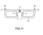
- Fig. 11 is a diagrammatic view for describing the position of each of the notification sections disposed on the base portion.
- the imaging notification sections 89 are disposed so that they are layered on the image drawing notification sections 12, as shown in Fig. 11 .
- Light having exited out of the imaging notification sections 89 is visible from the front, the right side, and the left side of the base portion 83.
- the present embodiment provides, at least, the following advantageous effect.
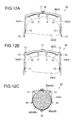
- FIG. 12A to 12C Another embodiment of the image display apparatus will be described next with reference to Figs. 12A to 12C .
- the present embodiment differs from the first embodiment in that the image drawing notification sections 12 are disposed in different positions. The same points as those in the first embodiment will not be described.
- Figs. 12A to 12C are diagrammatic plan views for describing the positions where the image drawing notification sections are disposed. That is, in an image display apparatus 92, the image drawing notification sections 12 are disposed on the frame 3b and the sidepieces 3a, as shown in Fig. 12A .
- the image drawing notification section 12 disposed on the frame 3b is specifically disposed at the center thereof facing the forehead of the head 2a.
- the image drawing notification section 12 disposed in this position is visible from the front, the top of the head, and the lateral sides of the viewer 2.
- the image drawing notification sections 12 disposed on the sidepieces 3a are specifically disposed on the right and left sides and on the side toward the back of the head.
- the image drawing notification sections 12 disposed in these positions are visible from the rear and the lateral sides of the viewer 2.
- the image drawing notification sections 12 can therefore diffuse the notification laser light 16b in the frontward, rearward, rightward, and leftward directions with respect to the viewer 2.
- the image drawing notification sections 12 are disposed on the frame 3b and the sidepieces 3a, as shown in Fig. 12B .
- the image drawing notification sections 12 disposed on the frame 3b are specifically disposed on the right and left sides.
- the image drawing notification sections 12 disposed in these positions are visible from the center, right, and left with respect to a position in front of the viewer 2.
- the image drawing notification sections 12 disposed on the sidepieces 3a are specifically disposed on the front right and left portions.
- the image drawing notification sections 12 disposed in these positions are visible from the right and left sides of the viewer 2.
- the image drawing notification sections 12 can therefore diffuse the notification laser light 16b frontward, rightward, and leftward with respect to the viewer 2.
- An image display apparatus 94 includes a base portion 95 as the support, and the base portion 95 is formed of a frame portion 95a, a first wrap portion 95b, and a second wrap portion 95c, as shown in Fig. 12C .
- the first wrap portion 95b is connected to the left end of the frame portion 95a and extends along the head 2a of the viewer 2 on the left in Fig. 12C .
- the second wrap portion 95c is connected to the right end of the frame portion 95a and extends along the head 2a of the viewer 2 on the right in Fig. 12C .
- the first wrap portion 95b and the second wrap portion 95c overlap with each other.
- Each of the first wrap portion 95b and the second wrap portion 95c is provided with a surface fastener, which allows the first wrap portion 95b and the second wrap portion 95c to repeatedly engage with each other and disengage from each other.
- the first wrap portion 95b and the second wrap portion 95c do not necessarily engage with each other via surface fasteners but may, for example, be bonded to each other via a hook or a button.
- the image drawing notification sections 12 are disposed on right and left portions of the frame portion 95a on the side of the top of the head.
- the image drawing notification sections 12 disposed in these positions can diffuse the notification laser light 16b in central, rightward, and leftward directions with respect to a position in front of the viewer 2.
- the image drawing notification section 12 disposed on the second wrap portion 95c is specifically disposed on the rear of the head 2a.
- the image drawing notification section 12 disposed in this position can diffuse the notification laser light 16b rearward, rightward, and leftward with respect to the viewer 2.
- the image drawing notification sections 12 can therefore diffuse the notification laser light 16b frontward, rearward, rightward, and leftward with respect to the viewer 2.
- FIG. 13A to 13C Another embodiment of the image display apparatus will be described next with reference to Figs. 13A to 13C .
- the present embodiment differs from the first embodiment in that the image drawing notification sections 12 are differently structured. The same points as those in the first embodiment will not be described.
- Figs. 13A to 13C are diagrammatic side cross-sectional views showing a variety of structures of the image drawing notification sections.
- Figs. 13A, 13B, and 13C show different forms of the image drawing notification sections. That is, as shown in Fig. 13A , an image drawing notification section 98 as the notification section includes a cylindrical base 99, and a hole is formed through the base 99 in the upward/downward direction in Fig. 13A .
- the notification optical fiber 15a is inserted into the hole and fixed therein.
- the notification laser light 16b exits out of the notification optical fiber 15a upward in Fig. 13A .
- a light diffuser 100 is disposed above the notification optical fiber 15a in Fig. 13A .
- the light diffuser 100 is made of a light transmissive material, has a circular columnar shape, and has air bubbles present therein.
- the density of the air bubbles increases with distance from the notification optical fiber 15a.
- the air bubbles may be replaced with particles that reflect light.
- the particles can be metal particles or pieces produced by minutely cutting a metal thin film.
- the laser light 16b passes through the light diffuser 100, the laser light is diffused and redirected in a variety of directions.
- An exterior portion 101 is provided so that it covers the light diffuser 100.
- the exterior portion 101 has a cylindrical shape having a bottom and transmits light. The notification laser light 16b therefore passes through the exterior portion 101 and travels in the diffused directions.
- an image drawing notification section 102 as the notification section includes a cylindrical base 103, and a hole is formed through the base 103 in the upward/downward direction in Fig. 13B .
- the notification optical fiber 15a is inserted into the hole and fixed therein.
- the notification laser light 16b exits out of the notification optical fiber 15a upward in Fig. 13B .
- a light diffuser 104 is provided above the notification optical fiber 15a in Fig. 13B with a space therebetween.
- the light diffuser 104 is made of a light transmissive material, has a conical shape, and has a pattern 104a formed of minutes dots and provided on the surface of the light diffuser.
- the pattern 104a may be made of a pigment that reflects and diffuses light, for example, in a printing process.
- the pigment can, for example, be silver white, titanium white, or zinc white.
- the notification laser light 16b is reflected off and diffused by the pattern 104a of the light diffuser 104.
- the notification laser light 16b that passes through the light diffuser 104 travels straight.
- An exterior portion 105 is provided so that it covers the light diffuser 104.
- the exterior portion 105 has a cylindrical shape having a bottom and transmits light. The notification laser light 16b therefore passes through the exterior portion 105 and travels in the diffused directions.
- an image drawing notification section 106 as the notification section includes a cylindrical base 107, and a hole is formed through the base 107 in the upward/downward direction in Fig. 13C .
- the notification optical fiber 15a is inserted into the hole and fixed therein.
- the notification laser light 16b exits out of the notification optical fiber 15a upward in Fig. 13C .
- a light diffuser 108 is provided above the notification optical fiber 15a in Fig. 13C .
- the light diffuser 108 is made of a light transmissive material, has a circular columnar shape, and has a pattern 108a formed of minutes dots and provided on the surface of the light diffuser.
- the pattern 108a may be made of a pigment that reflects and diffuses light, for example, in a printing process.
- the pigment can, for example, be silver white, titanium white, or zinc white.
- the notification laser light 16b is reflected off and diffused by the pattern 108a of the light diffuser 108.
- the notification laser light 16b incident on the light diffuser 108 is reflected off the surface of the light diffuser 108.
- the notification laser light 16b is diffused when it impinges on the pattern 108a.
- An exterior portion 109 is provided so that it covers the light diffuser 108, and a space filled with air is created between the light diffuser 108 and the exterior portion 109.
- the exterior portion 109 has a cylindrical shape having a bottom and transmits light. The notification laser light 16b therefore passes through the exterior portion 109 and travels in the diffused directions.
- the present embodiment provides, at least, the following advantageous effect.
- the half-silvered mirrors 10 are disposed inside the frame 3b.
- Each of the half-silvered mirrors 10 may be replaced with a total reflection mirror.
- the viewer 2 can concentrate on observing video images drawn by the image display apparatus.
- the image drawing notification sections 12 can notify that image drawing is underway also in this case.
- only one imaging section 11 is provided at the center of the frame 3b.
- Two imaging sections 11 may be provided on the frame 3b for stereoscopic imaging. In this case, the imaging sections are preferably disposed with a distance therebetween. Images that provide a greater amount of stereoscopic sensation can be provided.
- Two microphones 11a may also be provided for stereoscopic recording. Sound that provides a wide spatial sensation can be recorded.
- each of the image drawing notification sections 12 has a circular columnar shape.
- Each of the image drawing notification sections 12 does not necessarily have a specific shape and may, for example, have a spherical shape, a spindle shape, a box-like shape, a cubic shape, or a polyhedral shape.
- Each of the image drawing notification sections 12 may have a shape according to the exterior shape of the image display apparatus 1. In this case, a variety of exterior shapes of the image display apparatus can be provided.
- the right-side green light source 26, the right-side blue light source 27, and the right-side red light source 28 are provided to draw a color image.
- a color image is not necessarily drawn, and a black-and-white image may be drawn.
- the number of light sources, mirrors, and other components can be reduced to provide a compact, lightweight image display apparatus.
- light sources for the right eye 2e and light sources for the left eye 2f are provided for stereoscopic image drawing.
- the same image may be drawn to be viewed with the right eye 2e and the left eye 2f.
- the number of light sources, mirrors, and other components can be reduced to provide a compact, lightweight image display apparatus.
- the image drawing notification sections 12 are emitting light during image drawing operation to notify that the image drawing is underway.
- the image drawing notification sections 12 may be caused to emit light in a flashing manner when the imaging section 11 is used to perform imaging operation to notify that the imaging is underway. Further, when image drawing and imaging are simultaneously performed, the frequency at which the image drawing notification sections 12 emit light in a flashing manner may be changed or a pattern according to which the image drawing notification sections 12 emit light in a flashing manner may be changed. Only one image drawing notification section 12 may be used to notify that image drawing is underway, that imaging is underway, and that image drawing and imaging are underway.
- the laser light 16 outputted from red light sources causes the image drawing notification sections 12 to emit light.
- blue or green laser light 16 may cause the image drawing notification sections 12 to emit light.
- any two of the color laser light beams 16 or the three color laser light beams 16 may be combined with each other. Since the number of colors of the light diffused through the image drawing notification sections 12 can be increased, notification can be issued by using an optimum color.
- a reflection film is used to split the laser light 16.
- Another method for splitting the laser light 16 may be used.
- the laser light 16 may be caused to be incident on the interface between materials having different refractive indices.
- the angle of incidence at which the laser light 16 is incident on the interface may be changed to cause part of the laser light 16 to be reflected off or pass through the interface.
- the laser light 16 may be split by using a combination of diffraction gratings.
- variable ND filter 33 controls the notification laser light 16b in such a way that the power thereof is not greater than the power judgment value 55.
- the variable ND filter 33 may be replaced with an ND filer having a fixed attenuation factor. Since no member for controlling the attenuation factor is required, the image display apparatus 1 can be more readily manufactured.
- the base portion 3 is securely mounted on the head 2a with the base portion 3 supported by the ears 2b and the nose 2d.
- How to securely place the frame 3b on the head 2a is not limited to the technique described above.
- the frame 3b may be placed on a hat.
- a support that extends from the frame 3b via the top of the head 2a to the rear of the head 2a may be provided.
- the frame 3b may be readily placed in an arbitrary manner.
- the power of the image drawing laser light 16a is set to be lower than the power of the notification laser light 16b.
- the power of the image drawing laser light 16a may instead be equal to or higher than the power of the notification laser light 16b.
- the power may be changed so that the output light is readily viewed and hence visible notification of image drawing operation is readily recognized.
- the right-side green light source 26 to the left-side red light source 31 are disposed in the display control unit 69.
- the right-side green light source 26 to the left-side red light source 31 may be disposed in the base portion 70.
- no light-source optical fiber 71 is present between the display control unit 69 and the base portion 70 but only the wiring lines are present, whereby the tube can be more flexible.
- the splitters 59 and 62 in the second embodiment described above are used in place of the first half-silvered mirror 32 in the first embodiment. Further, the splitters 59 and 62 may be used in place of the first half-silvered mirror 32 in the third embodiment. Moreover, the splitters 59 and 62 may be used in place of the first half-silvered mirror 32 in the fifth embodiment. Still further, the splitters 59 and 62 may be used in place of the fourth half-silvered mirror 86 in the fifth embodiment.
- the imaging notification section 89 in the fifth embodiment described above may be used with the base portion 70 in the third embodiment. In this case as well, whether the imaging section 11 is performing imaging can be notified.
- the image drawing notification section 98, the image drawing notification section 102, and the image drawing notification section 106 in the seventh embodiment described above can be used in place of not only the image drawing notification sections 12 in the first embodiment but also the imaging notification section 89.
- the image drawing notification sections 98, 102, and 106 can also be used in each of the second to sixth embodiments.
Landscapes
- Physics & Mathematics (AREA)
- General Physics & Mathematics (AREA)
- Optics & Photonics (AREA)
- Engineering & Computer Science (AREA)
- Multimedia (AREA)
- Signal Processing (AREA)
Abstract
Description
- The present invention relates to an image display apparatus.
- An image apparatus mounted on the head of a person is known.
JP-A-2009-86365 JP-A-2009-86365 - When the optical axis of an optical fiber is shifted as in
JP-A-2009-86365 - An advantage of some aspects of the invention is to provide an image display apparatus that allows efficient use of light.
- The invention can be implemented as the following aspects or application examples.
- This application example is directed to an image display apparatus mounted around on head of a person, the apparatus including a light source that emits laser light, a splitter that splits the laser light into first laser light and second laser light having a different power than the first laser light, an image drawing section that causes the first laser light to be reflected off a mirror and causes the mirror to make pivotal motion to perform image drawing, a controller that controls the pivotal motion of the mirror, and a notification section that notifies other persons by diffusing the second laser light that the image drawing section is performing image drawing with.
- According to this application example, the light source emits laser light toward the splitter. The splitter splits the laser light into the first laser light and the second laser light. The split laser light beams travel as follows: the first laser light impinges on the image drawing section; and the second laser light impinges on the notification section. The image drawing section includes a mirror, and the first laser light impinges on the mirror. The controller controls pivotal motion of the mirror to change the direction in which the first laser light travels for image drawing. When the image drawing section is performing image drawing, the notification section diffuses the second laser light to notify (e.g., make readily apparent, alert or broadcast) that the image drawing is underway. When the image drawing section is not performing image drawing, the light source emits no laser light, and no second laser light is therefore diffused. As a result, whether or not the image display apparatus is performing image drawing can be notified. The image display apparatus uses the laser light emitted from the light source both in the image drawing and notification operation, whereby the laser light can be efficiently used.
- This application example is directed to the image display apparatus according to the application example described above, wherein the power of the first laser light is lower than the power of the second laser light.
- According to this application example, the laser light is split so that the power of the first laser light is lower than the power of the second laser light. When the amount of laser light emitted from the light source is very small, the power of the first laser light is unstable. The light source is therefore operated to emit laser light the amount of which is large enough to ensure stable light emission operation. In this case, when the split first laser light has a high power, the first laser light having undergone image drawing operation may damage the eyes. In this application example, the power of the second laser light is set to be higher than the power of the first laser light. Therefore, even when the light source emits laser light having a high power, the first laser light has a low power and image drawing can be performed by using the first laser light having a safe power.
- This application example is directed to the image display apparatus according to the application example described above, wherein the splitter splits the laser light into the first laser light and the second laser light using a reflection film that transmits part of the laser light.
- According to this application example, the splitter includes a reflection film. A reflection film reflects a greater amount of light when the thickness thereof is greater, whereas transmitting a greater amount of light when the thickness thereof is smaller. The splitter can therefore readily adjust the optical intensities of the first laser light and the second laser light.
- This application example is directed to the image display apparatus according to the application example described above, wherein the laser light is formed of a plurality of light rays having different colors, and the splitter combines the plurality of light rays with each other and separates the plurality of light rays from each other.
- According to this application example, the light source emits laser light formed of a plurality of light rays. The image drawing section can therefore perform image drawing with a large number of color light beams. The splitter combines the light beams with each other and separates the light beams from each other simultaneously. The image display apparatus can therefore be readily manufactured because the apparatus is simplified as compared with a case where an optical system that combines the light beams with each other and an optical system that separates the light beams from each other are separate optical systems.
- This application example is directed to the image display apparatus according to the application example described above, wherein the second laser light is red laser light.
- According to this application example, the second laser light is red laser light, and the notification section diffuses the red light. Red light is more noticeable than blue light and green light. The notification section can therefore noticeably notify that image drawing is underway.
- This application example is directed to the image display apparatus according to the application example described above, wherein the laser light is guided through a light-source optical fiber, the first laser light is guided through a first optical fiber, and the second laser light is guided through a second optical fiber, and in the splitter, an end surface of the light-source optical fiber is connected to an end surface of the first optical fiber and an end surface of the second optical fiber, and the area of the end surface of the first optical fiber where the end surface of the first optical fiber is connected to the end surface of the light-source optical fiber is narrower than the area of the end surface of the second optical fiber where the end surface of the second optical fiber is connected to the end surface of the light-source optical fiber.
- According to this application example, part of the laser light having exited out of the light-source optical fiber is incident on the first optical fiber, and part of the laser light is incident on the second optical fiber. The light incident area of the end surface of the first optical fiber is narrower than the light incident area of the end surface of the second optical fiber. The power of the first laser light incident on the first optical fiber can therefore be lower than the power of the second laser light incident on the second optical fiber.
- This application example is directed to the image display apparatus according to the application example described above, wherein the image display apparatus further includes an imaging section, and the notification section diffuses the second laser light to notify that the imaging section is performing imaging.
- According to this application example, the notification section uses the second laser light to notify whether or not the imaging section is performing imaging. Using no second laser light requires a notification light source. The image display apparatus can therefore be readily manufactured because the apparatus can be simplified as compared with a case where a light source for notifying whether the imaging section is performing imaging is provided.
- This application example is directed to the image display apparatus according to the application example described above, wherein the image display apparatus further includes a light attenuator that attenuates the power of the second laser light.
- According to this application example, the light attenuator adjusts the power of the second laser light. The light attenuator can therefore prevent the light diffused by the notification section from being too glaring.
- This application example is directed to the image display apparatus according to the application example described above, wherein the light attenuator attenuates the second laser light in accordance with the power of the second laser light to suppress change in the power of the second laser light diffused by the notification section.
- According to this application example, the light attenuator attenuates the second laser light when the power thereof is high to prevent change in the power of the second laser light diffused by the notification section. The light attenuator therefore allows the light diffused by the notification section to have a readily recognizable power.
- This application example is directed to the image display apparatus according to the application example described above, wherein the image display apparatus further includes a support that supports the image drawing section with the aid of the head of the person, and the notification section is disposed on the support in a position visible from the front and lateral sides of the head of the person.
- According to this application example, the notification section is disposed on the support, and a person who looks at the head of the person from the front can check the notification section. Further, a person who looks at the head of the person from either of the lateral sides can also check the notification section. The notification section can therefore issue notification forward and sideways with respect to the person to notify that the image display apparatus is performing image drawing.
- This application example is directed to the image display apparatus according to the application example described above, wherein the notification section is disposed on the support in a position visible from the lateral side on the right and the lateral side on the left when viewed from the front of the head of the person.
- According to this application example, the notification section is visible from both right and left sides of the head of the person viewed from the front. Since the notification section can therefore readily be recognized from both sides of the person, the notification section can issue notification within a wide angular range to notify that the image display apparatus is performing image drawing.
- This application example is directed to an image display apparatus mounted on the head of a person, the apparatus including a light source that emits laser light, a splitter that splits the laser light into first laser light and second laser light different from the first laser light in terms of power, an image drawing section that performs image drawing by using the first laser light, and a notification section that notifies other persons by using the second laser light that the image drawing section is performing image drawing.
- According to this application example, the light source emits laser light toward the splitter. The splitter splits the laser light into the first laser light and the second laser light. The split laser light beams travel as follows: The first laser light impinges on the image drawing section; and the second laser light impinges on the notification section. The image drawing section performs image drawing by using the first laser light. When the image drawing section is performing image drawing, the notification section diffuses the second laser light to notify that the image drawing is underway. When the image drawing section is not performing image drawing, the light source emits no laser light, and no second laser light is therefore diffused. As a result, whether or not the image display apparatus is performing image drawing can be notified. The image display apparatus uses the laser light emitted from the light source both in the image drawing and notification operation, whereby the laser light can be efficiently used.
- This application example is directed to the image display apparatus according to the application example described above, wherein the power of the first laser light is lower than the power of the second laser light.
- According to this application example, the laser light is split so that the power of the first laser light is lower than the power of the second laser light. When the amount of laser light emitted from the light source is very small, the power of the first laser light is unstable. The light source is therefore operated to emit laser light the amount of which is large enough to ensure stable light emission operation. In this case, when the split first laser light has a high power, the first laser light having undergone image drawing operation may damage the eyes. In this application example, the power of the second laser light is set to be higher than the power of the first laser light. Therefore, even when the light source emits laser light having a high power, the first laser light has a low power and image drawing can be performed by using the first laser light having a safe power.
- Embodiment of the invention will be described with reference to the accompanying drawings, wherein like numbers reference like elements.
-
Fig. 1 is a schematic perspective view showing the structure of an image display apparatus according to a first embodiment. -
Fig. 2 is a diagrammatic plan view showing the structure of the image display apparatus. -
Fig. 3 is an electrical control block diagram showing the structure of the image display apparatus. -
Fig. 4A is a diagrammatic side cross-sectional view showing the structure of a scanning optical output section, andFig. 4B is a diagrammatic plan view showing the structure of a scanner. -
Fig. 5A is a diagrammatic cross-sectional view showing the structure of a notification section,Fig. 5B is a diagrammatic cross-sectional view showing the structure of a variable ND filter, andFig. 5C is a diagrammatic plan view showing the structure of a disk filter. -
Fig. 6A is a graph showing the relationship between the power of laser light inputted to the variable ND filter and the attenuation factor of a disk filter, andFig. 6B is a graph showing the relationship between the power of the laser light inputted to the variable ND filter and the power of output light outputted from the variable ND filter. -
Figs. 7A to 7C relate to a second embodiment,Fig. 7A is a diagrammatic side cross-sectional view showing the structure of a splitter,Fig. 7B is a diagrammatic plan cross-sectional view showing the structure of the splitter, andFig. 7C is a diagrammatic side cross-sectional view showing the structure of another splitter. -
Fig. 8 is an electrical control block diagram showing the structure of an image display apparatus according to a third embodiment. -
Fig. 9 is a diagrammatic plan view showing the structure of an image display apparatus according to a fourth embodiment. -
Fig. 10 is an electrical control block diagram showing the structure of an image display apparatus according to a fifth embodiment. -
Fig. 11 is a diagrammatic view for describing the position of each notification section disposed on a base portion. -
Figs. 12A to 12C relate to a sixth embodiment and are diagrammatic plan views for describing the positions where image drawing notification sections are provided. -
Figs. 13A to 13C relate to a seventh embodiment and are diagrammatic side cross-sectional views showing a variety of structures of each of the image drawing notification sections. - A description will be made of characteristic examples of embodiments of an image display apparatus with reference to
Figs. 1 to 13A, 13B, and 13C . The embodiments will be described below with reference to the drawings. Each member is drawn in different scales so that the member is recognizably large in the drawings. - An image display apparatus according to a first embodiment will be described with reference to
Figs. 1 to 6A and 6B .Fig. 1 is a schematic perspective view showing the structure of the image display apparatus. The image display apparatus 1 is mounted on ahead 2a of aviewer 2, as shown inFig. 1 . The image display apparatus 1 includes abase portion 3 as a support having a shape similar to the frame of glasses. Thebase portion 3 includessidepieces 3a and aframe 3b. - When the image display apparatus is mounted on the
head 2a, thesidepieces 3a are located on the lateral sides of thehead 2a and sandwiched between thehead 2a andears 2b of theviewer 2. Thesidepieces 3a are attached to both ends of thebase portion 3 and located on the right and left sides of thehead 2a. Theframe 3b is disposed between the twosidepieces 3a. When the image display apparatus is mounted on thehead 2a, theframe 3b is located in front of thehead 2a in aposition facing eyes 2c of theviewer 2. A hinge is provided between theframe 3b and each of thesidepiece 3a. The hinges allow thesidepieces 3a to be folded relative to theframe 3b. A pair ofnose pads 4 are attached to theframe 3b and come into contact with anose 2d of theviewer 2. Among the components of thebase portion 3, thenose pads 4 and thesidepieces 3a come into contact with thehead 2a, and thebase portion 3 is supported with the aid of thenose pads 4 and thesidepieces 3a. - A
cable 5 is connected to one of thesidepieces 3a, and adisplay control unit 6 is connected to thecable 5. Thecable 5 has an electric wiring line and an optical fiber built therein. Thedisplay control unit 6 is connected to a video recording/reproducingapparatus 8 via acable 7. - The
base portion 3 is provided with scanningoptical output sections 9 as a pair of image drawing sections above thenose pads 4 inFig. 1 , and half-silveredmirrors 10 are disposed as the pair of image drawing sections in positions facing theeyes 2c. Thebase portion 3 is further provided with animaging section 11 in a position between the pair of scanningoptical output sections 9, and theimaging section 11 has amicrophone 11a built therein. An imagedrawing notification section 12 is provided as a notification section having a circular columnar shape on thebase portion 3 on the upper side inFig. 1 in the vicinity of a portion where theframe 3b and each of thesidepiece 3a are connected to each other. In detail, the imagedrawing notification sections 12 are disposed on thebase portion 3 in positions visible from the front and lateral sides of thehead 2a. In other words, the imagedrawing notification sections 12 are disposed on thebase portion 3, when viewed from the front of thehead 2a, in a position visible from the right side and in a position visible from the left side. -
Fig. 2 is a diagrammatic plan view showing the structure of the image display apparatus. Aloudspeaker 13 is provided between thehead 2a and each of thesidepieces 3a, as shown inFig. 2 . Theloudspeaker 13 is preferably a bone-conduction loudspeaker. Anelectric wiring line 14 and anoptical fiber 15, which are extensions of those in thecable 5, are provided inside thesidepieces 3a and theframe 3b. The scanningoptical output sections 9, the bone-conduction loudspeakers 13, and theimaging section 11 are connected to theelectric wiring line 14 and driven by thedisplay control unit 6. - The scanning
optical output sections 9 and the imagedrawing notification sections 12 are connected to theoptical fiber 15 and receives laser light 16 from thedisplay control unit 6. The scanningoptical output sections 9 continuously deflect thelaser light 16 in upward, downward, rightward, and leftward directions and output the resultant light toward the half-silvered mirrors 10. The outputted laser light is reflected off the half-silveredmirrors 10 and travels toward theeyes 2c of theviewer 2. Theviewer 2 observes a virtual image formed by the image display apparatus 1. -
Fig. 3 is an electrical control block diagram showing the structure of the image display apparatus. Thedisplay control unit 6 provided in the image display apparatus 1 accommodates an input/output section 17, and the video recording/reproducingapparatus 8 is connected to the input/output section 17, as shown inFig. 3 . The video recording/reproducingapparatus 8 includes a storage section, which stores video image data, still image data, and audio data. The video recording/reproducingapparatus 8 outputs the video image data and the still image data to the input/output section 17. On the other hand, when the image display apparatus 1 outputs video image data, still image data, and audio data through the input/output section 17, the video recording/reproducingapparatus 8 receives the video image data, the still image data, and the audio data as inputs and stores them in the storage section. - The input/
output section 17 is provided with a connector, a switch, and a variable resistor (not shown). Thecable 7 is connected to the connector. The switch is disposed at a plurality of locations for power on/off operation of the image display apparatus 1, activation and deactivation of audio output, and other purposes. The variable resistor is disposed at a plurality of locations for adjustment of brightness of video images, adjustment of luminance of light through the imagedrawing notification sections 12, adjustment of volume of sound from the bone-conduction loudspeakers 13, and other purposes. - A
controller 20 is connected to the input/output section 17. Alight source driver 21, ascan driver 22, alight attenuation driver 23, aloudspeaker driver 24, animaging driver 25, and other components are connected to thecontroller 20, and thecontroller 20 controls action of each of the components. Specifically, when the input/output section 17 inputs a video signal from the video recording/reproducingapparatus 8 to thecontroller 20, thecontroller 20 outputs a luminance signal associated with video images and a luminance adjustment signal inputted to the corresponding variable resistor to thelight source driver 21. Further, when the input/output section 17 inputs the video signal to thecontroller 20, thecontroller 20 outputs a scan signal associated with the video images to thescan driver 22. In addition, thecontroller 20 outputs a red luminance signal that is part of the video signal to thelight attenuation driver 23. - A right-side
green light source 26, a right-side bluelight source 27, a right-sidered light source 28, a left-sidegreen light source 29, a left-side bluelight source 30, and a left-sidered light source 31 are connected to thelight source driver 21. The right-sidegreen light source 26, the right-side bluelight source 27, and the right-sidered light source 28 supply thelaser light 16 to the scanningoptical output section 9 that outputs thelaser light 16 to theright eye 2e. The left-sidegreen light source 29, the left-side bluelight source 30, and the left-sidered light source 31 supply thelaser light 16 to the scanningoptical output section 9 that outputs thelaser light 16 to theleft eye 2f. - When the video signal is a signal for a stereoscopic image, the video signal has a right-eye video signal to be observed with the
right eye 2e and a left-eye video signal to be observed with theleft eye 2f. When the video signal is a signal for a color image, each of the right-eye and left-eye video signals has a green signal, a blue signal, and a red signal. - The
light source driver 21 outputs electric power according to the video signal to each of the right-sidegreen light source 26 to the left-sidered light source 31. In detail, electric power according to the green signal of the right-eye video signal is outputted to the right-sidegreen light source 26, and electric power according to the blue signal of the right-eye video signal is outputted to the right-side bluelight source 27. Further, electric power according to the red signal of the right-eye video signal is outputted to the right-sidered light source 28. Similarly, electric power according to the green signal of the left-eye video signal is outputted to the left-sidegreen light source 29, and electric power according to the blue signal of the left-eye video signal is outputted to the left-side bluelight source 30. Further, electric power according to the red signal of the left-eye video signal is outputted to the left-sidered light source 31. - Each of the right-side
green light source 26 and the right-side bluelight source 27 has an ND (neutral density) filter built therein. The attenuation factor of the ND filter is not limited to a specific value, butlaser light 16 having a magnitude of about 1/10000 of the amount of laser light emitted from the light source is outputted through the ND filter in the present embodiment. The light emitted from the right-sidered light source 28 is not attenuated and the entire amount of laser light is outputted. - The
laser light 16 emitted from the right-sidered light source 28 impinges on a first half-silveredmirror 32, which works as a splitter. Part of thelaser light 16 emitted from the right-sidered light source 28 is reflected off and redirected by the first half-silveredmirror 32 to form image drawinglaser light 16a as first laser light. The ratio of the amount of image drawinglaser light 16a to the amount oflaser light 16 emitted from the right-sidered light source 28 is not limited to a specific value and is about 1/500000 to 1/1000000 in the present embodiment. For example, in the present embodiment, thelaser light 16 emitted from the right-sidered light source 28 has an power ranging from 100 to 150 mW, and the image drawinglaser light 16a has an power ranging from 200 to 300 nW.Notification laser light 16b having the remaining amount (power) of light as second laser light travels straight through the first half-silveredmirror 32 and impinges on avariable ND filter 33, which works as a light attenuator. Therefore, the image drawinglaser light 16a is reflected off the first half-silveredmirror 32, and thenotification laser light 16b exits through the first half-silveredmirror 32 at the same time. The power of the image drawinglaser light 16a is lower than the power of thenotification laser light 16b. Thevariable ND filter 33 attenuates thenotification laser light 16b passing therethrough, and the attenuation factor of thevariable ND filter 33 is changed by thelight attenuation driver 23, which drives thevariable ND filter 33. - The
notification laser light 16b having passed through thevariable ND filter 33 impinges on a focusinglens 34. Thenotification laser light 16b having passed through the focusinglens 34 impinges on a notificationoptical fiber 15a as a second optical fiber. The focusinglens 34 focuses thenotification laser light 16b to the center of an end surface of the notificationoptical fiber 15a. The focusinglens 34 can thus guide thenotification laser light 16b into the notificationoptical fiber 15a with a small amount of accompanied loss. - The image
drawing notification section 12 is disposed on the opposite end of the notificationoptical fiber 15a to the focusinglens 34. The imagedrawing notification section 12 is disposed on thebase portion 3 in the vicinity of theright eye 2e. Thenotification laser light 16b having guided through the notificationoptical fiber 15a is diffused by the imagedrawing notification section 12. A person who looks at the imagedrawing notification section 12 is notified that theviewer 2 is observing video images. - The red image drawing
laser light 16a reflected off the first half-silveredmirror 32 impinges on a second half-silveredmirror 35, which works as the splitter, and part of the laser light passes through the second half-silveredmirror 35. Theblue laser light 16 emitted from the right-side bluelight source 27 also impinges on the second half-silveredmirror 35, and part of the laser light is reflected off and redirected by the second half-silveredmirror 35. The red image drawinglaser light 16a having passed through the second half-silveredmirror 35 and the blue image drawinglaser light 16a having been reflected off the second half-silveredmirror 35 are combined with each other, and the combined laser light impinges on a third half-silveredmirror 36, which works as the splitter. - Part of both the red and blue image drawing
laser light 16a having impinged on the third half-silveredmirror 36 is reflected off the third half-silveredmirror 36 and impinges on a focusinglens 37. The green laser light 16 outputted from the right-sidegreen light source 26 also impinges on the third half-silveredmirror 36, and part of the laser light passes through the third half-silveredmirror 36 and impinges on the focusinglens 37. The red, blue, and green image drawinglaser light beams 16a having impinged on the focusinglens 37 are combined with each other, and the focusinglens 37 focuses the combined light to the center of an end surface of an image drawingoptical fiber 15b as a first optical fiber. The focusinglens 37 can thus guide the image drawinglaser light 16a into the image drawingoptical fiber 15b with a small amount of accompanied loss. - The first half-silvered
mirror 32 to the third half-silveredmirror 36 form the splitter, and each of the half-silvered mirrors is provided with a reflection film. The reflection films are therefore used to separate thelaser light 16 outputted from the right-sidegreen light source 26 to the right-sidered light source 28 into the image drawinglaser light 16a and thenotification laser light 16b. A reflection film reflects a greater amount of light when the thickness thereof is greater, whereas transmitting a greater amount of light when the thickness thereof is smaller. The first half-silveredmirror 32 can therefore readily adjust the optical intensities of the image drawinglaser light 16a and thenotification laser light 16b. - One of the scanning
optical output sections 9 is disposed at the opposite end of the image drawingoptical fiber 15b to the focusinglens 37. The image drawinglaser light 16a guided through the image drawingoptical fiber 15b impinges on the scanningoptical output section 9. The scanningoptical output section 9 is provided with a mirror and causes the mirror to make pivotal motion in upward, downward, rightward, and leftward directions. The image drawinglaser light 16a having impinged on the scanningoptical output section 9 is redirected by the scanningoptical output section 9 and impinges on the half-silveredmirror 10. Thescan driver 22 controls the pivotal motion of the mirror in the scanningoptical output section 9 to cause the mirror to scan the half-silveredmirror 10 with the image drawinglaser light 16a. The image drawinglaser light 16a reflected off the half-silveredmirror 10 impinges on theright eye 2e. - The image drawing
laser light 16a that impinges on theright eye 2e has been modulated in terms of luminance based on the video signal and has undergone the scanning of the half-silveredmirror 10. Theviewer 2 can therefore observe a virtual image drawn on the half-silveredmirror 10. - The path along which the
laser light 16 outputted from the left-sidegreen light source 29 to the left-sidered light source 31 travels and reaches theleft eye 2f is the same as the path along which thelaser light 16 outputted from the right-sidegreen light source 26 to the right-sidered light source 28 travels and reaches theright eye 2e, and no description of the path associated with the left-side light sources will therefore be made. - When the input/
output section 17 inputs the audio signal to thecontroller 20 from the video recording/reproducingapparatus 8, thecontroller 20 outputs the audio signal and a volume adjustment signal inputted to the corresponding variable resistor to theloudspeaker driver 24. Theloudspeaker driver 24 outputs a drive signal produced by amplifying the audio signal in accordance with the volume adjustment signal. The pair of bone-conduction loudspeakers 13 are connected to theloudspeaker driver 24 and driven by the drive signal. - The
imaging section 11 and themicrophone 11a are connected to theimaging driver 25. Theimaging driver 25 drives theimaging section 11 to perform imaging and outputs the resultant video signal. Theimaging driver 25 further drives themicrophone 11a to convert sound into an audio signal. After theimaging driver 25 outputs the video signal and the audio signal to thecontroller 20, thecontroller 20 outputs the video signal and the audio signal to the video recording/reproducingapparatus 8 via the input/output section 17. The video recording/reproducingapparatus 8 receives the video signal and the audio signal as inputs and stores them. -
Fig. 4A is a diagrammatic side cross-sectional view showing the structure of each of the scanning optical output sections, andFig. 4B is a diagrammatic plan view showing the structure of a scanner. The scanningoptical output section 9 includes asubstrate 40, and thesubstrate 40 has a cavity formed therein, as shown inFig. 4A . A hole is provided in thesubstrate 40 in an upper portion thereof inFig. 4A , and the axis of the hole extends in the upward/downward direction. The image drawingoptical fiber 15b is inserted into the hole and fixed therein. Acoupling lens 41 is provided below the image drawingoptical fiber 15b inFig. 4A , and the image drawinglaser light 16a having exited out of the image drawingoptical fiber 15b passes through thecoupling lens 41. - The
coupling lens 41 adjusts the spot diameter of the image drawinglaser light 16a having exited out of the image drawingoptical fiber 15b. Thecoupling lens 41 further has a function of a collimator lens that parallelizes the image drawinglaser light 16a. Ascanner 42 is provided below thecoupling lens 41 inFig. 4A . Thescanner 42 has amirror 42a formed at the center of the surface of the scanner that faces thecoupling lens 41. The image drawinglaser light 16a having passed through thecoupling lens 41 is incident on themirror 42a, reflected off and redirected by themirror 42a. - A
magnet 43 is provided on the opposite surface of thescanner 42 to the mirror with a pair ofsupports 42f interposed between the surface and themagnet 43. Anelectromagnet 44 is provided in thesubstrate 40 on the side where themagnet 43 is disposed with respect to thescanner 42, and theelectromagnet 44 exerts an attractive force or a repulsive force on themagnet 43. Thecontroller 20 drives thescanner 42 by instructing thescan driver 22 to supply theelectromagnet 44 with a current having a sawtoothvertical scan waveform 45 and a current having a sinusoidalhorizontal scan waveform 46. The two waveforms are formed so that the frequency of thehorizontal scan waveform 46 is higher than the frequency of thevertical scan waveform 45. - A
collector lens 47 is provided in a position along the direction in which the image drawinglaser light 16a reflected off themirror 42a travels. Thecollector lens 47 is preferably an aspheric lens. The image drawinglaser light 16a passes through thecollector lens 47 and is reflected off the half-silveredmirror 10. Thecollector lens 47 collects the image drawinglaser light 16a in such a way that the image drawinglaser light 16a reflected off the half-silveredmirror 10 is parallelized. - As shown in
Fig. 4B , themirror 42a located at the center of thescanner 42 is supported byfirst beams 42b provided in the upward/downward direction inFig. 4B . Themirror 42a therefore pivots around thefirst beams 42b. Thefirst beams 42b are fixed to an annularfirst support frame 42c located around themirror 42a. Thefirst support frame 42c is provided with twosupports 42f, which support both ends of themagnet 43. Thefirst support frame 42c is supported bysecond beams 42d provided in the rightward/leftward direction inFig. 4B . Thefirst support frame 42c therefore pivots around thesecond beams 42d. Thesecond beams 42d are fixed to a rectangularsecond support frame 42e located around thefirst support frame 42c, and thesecond support frame 42e is fixed to thesubstrate 40. - The current having the
vertical scan waveform 45 and the current having thehorizontal scan waveform 46 are conducted through theelectromagnet 44. The natural frequency of themirror 42a, which pivots around thefirst beams 42b, is equal to the frequency of thehorizontal scan waveform 46. Themirror 42 therefore pivots around thefirst beams 42b in response to thehorizontal scan waveform 46. The natural frequency of thefirst support frame 42c and themirror 42a, which pivot around thesecond beams 42d, is equal to the frequency of thevertical scan waveform 45. Themirror 42a therefore pivots around thesecond beams 42d in response to thevertical scan waveform 45. - The axial direction of the pivotal motion around the
first beams 42b is perpendicular to the axial direction of the pivotal motion around thesecond beams 42d. When themirror 42a pivots around thesecond beams 42d, the position where thelaser light 16 impinges on the half-silveredmirror 10 moves in the upward/downward direction with respect to theviewer 2. Thelaser light 16 thus undergoes vertical scanning. When themirror 42a pivots around thefirst beams 42b, the position where thelaser light 16 impinges on the half-silveredmirror 10 moves in the rightward/leftward direction with respect to theviewer 2. Thelaser light 16 thus undergoes horizontal scanning. Themirror 42a causes thelaser light 16 to undergo horizontal scanning in response to thehorizontal scan waveform 46 and vertical scanning in response to thevertical scan waveform 45. -
Fig. 5A is a diagrammatic cross-sectional view showing the structure of each of the notification sections. Each of the imagedrawing notification sections 12 includes acylindrical base 48, which has a hole formed through the base 48 in the upward/downward direction inFig. 5A . The notificationoptical fiber 15a is inserted into the hole and fixed therein. Thenotification laser light 16b exits upward inFig. 5A out of the notificationoptical fiber 15a. Adiffuser plate 49 is provided above the notificationoptical fiber 15a inFig. 5A . A large number of irregularities are formed on the surfaces of thediffuser plate 49. When thenotification laser light 16b passes through thediffuser plate 49, the laser light is diffused and redirected in a variety of directions. A circular columnar space is present above thediffuser plate 49 inFig. 5A , and anexterior portion 50 is provided so that it covers the space. Theexterior portion 50 has a cylindrical shape having a bottom and has a large number of irregularities formed on the inner surface thereof. When thenotification laser light 16b passes through theexterior portion 50, the laser light is therefore further diffused and redirected in a variety of directions. As a result, the power distribution of thelaser light 16 changes from an angled shape to a substantially spherical shape. -
Fig. 5B is a diagrammatic cross-sectional view showing the structure of the variable ND filter.Fig. 5C is a diagrammatic plan view showing the structure of a disk filter. Thevariable ND filter 33 includes asubstrate 51 having a box-like shape, as shown inFig. 5B . Two through holes are formed in thesubstrate 51, and a light-source-sideoptical fiber 15c is inserted into one of the through holes and fixed therein. Amotor 52 is provided in the other through hole. Themotor 52 is preferably a stepper motor, and the angle of rotation thereof is controlled by thelight attenuation driver 23. Adisk filter 53 having a circular-plate-like shape is attached to arotary shaft 52a of themotor 52 and located in a position facing the light-source-sideoptical fiber 15c. Thenotification laser light 16b having exited out of the light-source-sideoptical fiber 15c impinges on thedisk filter 53. - The focusing
lens 34 is disposed on the opposite side of thedisk filter 53 to the light-source-sideoptical fiber 15c. Thenotification laser light 16b having impinged on thedisk filter 53 passes through thedisk filter 53 and impinges on the focusinglens 34. The notificationoptical fiber 15a is disposed on the opposite side of the focusinglens 34 to thedisk filter 53. Thenotification laser light 16b having impinged on the focusinglens 34 passes through the focusinglens 34 and is focused on the end surface of the notificationoptical fiber 15a. Thenotification laser light 16b focused onto the notificationoptical fiber 15a travels through the notificationoptical fiber 15a. - The
disk filter 53 rotates around therotary shaft 52a and changes its attenuation factor at which thenotification laser light 16b is attenuated in accordance with the circumferential position where the laser light passes, as shown inFig. 5C . When themotor 52 rotates thedisk filter 53, the attenuation factor at which thelaser light 16 that passes through thedisk filter 53 is attenuated can be controlled in accordance with the angle of rotation. -
Fig. 6A is a graph showing the relationship between the power of the laser light that impinges on the variable ND filter and the attenuation factor of the disk filter.Fig. 6B is a graph showing the relationship between the power of the laser light that impinges on the variable ND filter and the power of output light having exited through the variable ND filter. - In
Fig. 6A , the horizontal axis represents the power of input light, and the power increases from left to right. The power along the horizontal axis represents the power of thenotification laser light 16b that exits out of the light-source-sideoptical fiber 15c and impinges on thevariable ND filter 33. The vertical axis represents the attenuation factor at which thevariable ND filter 33 attenuates thenotification laser light 16b. The attenuation factor decreases from above to below. The input light is thelaser light 16 that impinges on thedisk filter 53. Anattenuation factor line 54 represents the relationship between the power of the input light and the attenuation factor. - When the power of the input light is lower than a
power judgment value 55, thevariable ND filter 33 does not attenuate the input light, as indicated by theattenuation factor line 54. When the power of the input light is greater than thepower judgment value 55, thevariable ND filter 33 attenuates the input light in proportion to the power of the input light. - The
controller 20 outputs data that indicates the amount of light to be outputted from the right-sidered light source 28 to thelight source driver 21 and thelight attenuation driver 23. Thelight attenuation driver 23 performs an arithmetical operation on the data that indicates the amount of light by using predetermined parameters to calculate an estimated power of the input light. Thelight attenuation driver 23 then calculates the attenuation factor of thevariable ND filter 33 based on theattenuation factor line 54 and the estimated power of the input light. Thelight attenuation driver 23 then rotates themotor 52, to which thevariable ND filter 33 is attached, in such a way that the attenuation factor of thedisk filter 53 in a position where thenotification laser light 16b passes is equal to the calculated attenuation factor. Thevariable ND filter 33 thus attenuates thelaser light 16. - In
Fig. 6B , the horizontal axis represents the power of the input light, and the power increases from left to right. The output light is thelaser light 16 having passed through thedisk filter 53. The vertical axis represents the power of the output light, and the power decreases from above to below. The power along the vertical axis represents the power of thenotification laser light 16b outputted from thevariable ND filter 33 to the notificationoptical fiber 15a. - An
power correlation line 56 shows the relationship between the power of the input light and the power of the output light. When the power of the input light is smaller than or equal to thepower judgment value 55, the input light is not attenuated, and hence the power of the output light is equal to that of the input light, as indicated by thepower correlation line 56. When the power of the input light is greater than thepower judgment value 55, the input light is attenuated. As a result, the power of the output light is maintained at thepower judgment value 55. Thenotification laser light 16b diffused by the imagedrawing notification section 12 is thus limited to be smaller than or equal to a predetermined power. - The
laser light 16 outputted from the left-sidered light source 31 also passes through thevariable ND filter 33. Thevariable ND filter 33 attenuates thenotification laser light 16b associated with the left-side light source 31 in the same manner as thelaser light 16 outputted from the right-sidered light source 28 is attenuated. Thenotification laser light 16b diffused by the left imagedrawing notification section 12 is therefore also limited to be smaller than or equal to the predetermined power. - The above described embodiment provides, at least, the following advantageous effects.
- (1) According to the present embodiment, when the scanning
optical output sections 9 and the half-silveredmirrors 10 draw a virtual image, the imagedrawing notification sections 12 diffuse thenotification laser light 16b and notify (e.g., alerts) that image drawing is underway. The imagedrawing notification sections 12 can thus notify whether or not the image display apparatus 1 is performing image drawing. - (2) According to the present embodiment, the
laser light 16 is split so that the power of the image drawinglaser light 16a is lower than the power of thenotification laser light 16b. When each of the right-sidegreen light source 26 to the left-sidered light source 31 emitslaser light 16 having a very low power, the power is unstable. Each of the right-sidegreen light source 26 to the left-sidered light source 31 is therefore operated to emitlaser light 16 having an power high enough to ensure a stable power. In this case, when the split image drawinglaser light 16a has a high power, the eyes may be damaged. In the present embodiment, the power of thenotification laser light 16b is set to be higher than the power of the image drawinglaser light 16a. Therefore, even when each of the right-sidegreen light source 26 to the left-sidered light source 31 emitslaser light 16 having a high power, the image drawinglaser light 16a has a low power and image drawing can be performed by using the image drawinglaser light 16a having a safe power. - (3) According to the present embodiment, the first half-silvered
mirror 32 is provided with a reflection film. A reflection film reflects a greater amount of light when the thickness thereof is greater, whereas transmitting a greater amount of light when the thickness thereof is smaller. The first half-silveredmirror 32 can therefore readily adjust the optical intensities of the image drawinglaser light 16a and thenotification laser light 16b. - (4) According to the present embodiment, the right-side
green light source 26 to the right-sidered light source 28 emit green, blue, and red laser light beams 16, respectively. The first half-silveredmirror 32 to the third half-silveredmirror 36, each of which is provided with a reflection film, are used to combine the image drawinglaser light beams 16a with each other and separate the notification laser light beams 16b from the other light beams at the same time. The configuration of the apparatus can therefore be simplified as compared with a case where an optical system that combines the image drawinglaser light beams 16a with each other and an optical system that separates the notificationlaser light beam 16b from the other laser light beams are separate optical systems. - (5) According to the present embodiment, the
notification laser light 16b is red laser light, and the imagedrawing notification sections 12 diffuse the red light. Red light is more noticeable than blue light and green light. The imagedrawing notification sections 12 can therefore noticeably notify that image drawing is underway. - (6) According to the present embodiment, the
variable ND filter 33 adjusts the power of thenotification laser light 16b. Thevariable ND filter 33 can therefore prevent the light diffused by the imagedrawing notification sections 12 from being too glaring. - (7) According to the present embodiment, the
variable ND filter 33 attenuates thenotification laser light 16b when the power thereof is high to prevent change in the power of thenotification laser light 16b diffused by the imagedrawing notification sections 12. Thevariable ND filter 33 therefore allows thenotification laser light 16b diffused by the imagedrawing notification sections 12 to have a readily recognizable power. - (8) According to the present embodiment, the image
drawing notification sections 12 are disposed on thebase portion 3, and a person who looks at thehead 2a from the front can check the imagedrawing notification sections 12. Further, a person who looks at thehead 2a from either of the lateral sides can also check the imagedrawing notification sections 12. The imagedrawing notification sections 12 can therefore issue notification forward and sideways with respect to theviewer 2 to notify that the image display apparatus 1 is performing image drawing. - (9) According to the present embodiment, the image
drawing notification sections 12 are visible from both right and left sides of thehead 2a viewed from the front. Since the imagedrawing notification sections 12 can therefore readily be recognized from both sides of theviewer 2, the imagedrawing notification sections 12 can issue notification within a wide angular range to notify that the image display apparatus 1 is performing image drawing. - Another embodiment of the image display apparatus will be described next with reference to
Figs. 7A to 7C . The present embodiment differs from the first embodiment in that the first half-silveredmirror 32 is differently formed. The same points as those in the first embodiment will not be described. -
Fig. 7A is a diagrammatic side cross-sectional view showing the structure of the splitter. That is, in the present embodiment, the first half-silveredmirror 32 is replaced with asplitter 59, as shown inFig. 7A . Thesplitter 59 includes abase portion 60 having a box-like shape. A hole is formed in thebase portion 60 from above inFig. 7A to a depth equal to one-half the thickness of thebase portion 60, and a light-sourceoptical fiber 61 is inserted into the hole and fixed therein. The light-sourceoptical fiber 61 has a flat end surface on the lower side inFig. 7A . Thelaser light 16 from the right-sidered light source 28 impinges on the light-sourceoptical fiber 61. - Two holes are formed in the
base portion 60 from below inFig. 7A to a depth where the holes reach the light-sourceoptical fiber 61. The two holes communicate with each other in the radial direction. The notificationoptical fiber 15a is disposed in the hole on the right side inFig. 7A , and the image drawingoptical fiber 15b is disposed in the hole on the left side inFig. 7A . The notificationoptical fiber 15a and the image drawingoptical fiber 15b are fixed to thebase portion 60. Each of the notificationoptical fiber 15a and the image drawingoptical fiber 15b has a flat end surface on the upper side inFig. 7A . The end surface of the light-sourceoptical fiber 61 on the lower side inFig. 7A is in contact with the end surface of each of the notificationoptical fiber 15a and the image drawingoptical fiber 15b on the upper side inFig. 7A . It is preferable to provide a light transmissive resin or any other suitable material between the end surfaces so that the refractive index does not sharply change. Providing such a material prevents thelaser light 16 from being reflected off the end surfaces. -
Fig. 7B is a diagrammatic plan cross-sectional view showing the structure of the splitter taken along the line A-A' inFig. 7A . The notificationoptical fiber 15a and the image drawingoptical fiber 15b have flat surfaces where they come into contact with each other and are disposed so that they are in contact with each other, as shown inFig. 7B . The area of the end surface of the light-sourceoptical fiber 61 where it overlaps with the end surface of the image drawingoptical fiber 15b is narrower than the area of the end surface of the light-sourceoptical fiber 61 where it overlaps with the end surface of the notificationoptical fiber 15a. - The
laser light 16 having passed through the light-sourceoptical fiber 61 is therefore split into two laser light beams inputted to the notificationoptical fiber 15a and the image drawingoptical fiber 15b. The power of thelaser light 16 inputted to the image drawingoptical fiber 15b is lower than the power of thelaser light 16 inputted to the notificationoptical fiber 15a. Thelaser light 16 having passed through the light-sourceoptical fiber 61 has a Gaussian power distribution, and the power is maximized at the center of the light-sourceoptical fiber 61. The notificationoptical fiber 15a is in contact with the portion where the power is maximized. As a result, the power of thelaser light 16 inputted to the image drawingoptical fiber 15b is lower than the power of thelaser light 16 inputted to notificationoptical fiber 15a. - Another form of the splitter that splits the
laser light 16 will be introduced below.Fig. 7C is a diagrammatic side cross-sectional view showing the structure of the splitter. That is, the first half-silveredmirror 32 is replaced with asplitter 62, as shown inFig. 7C . Thesplitter 62 has abase portion 63 having a box-like shape. Acavity 63a is formed in a central portion of thebase portion 63. A hole is formed in thebase portion 63 from above inFig. 7C toward thecavity 63a, and the light-sourceoptical fiber 61 is inserted into the hole and fixed therein. The light-sourceoptical fiber 61 has a flat end surface on the lower side inFig. 7C . Thelaser light 16 from the right-sidered light source 28 impinges on the light-sourceoptical fiber 61. - Two holes are formed in the
base portion 63 from below inFig. 7C toward thecavity 63a. The notificationoptical fiber 15a is disposed in the hole on the right side inFig. 7C , and the image drawingoptical fiber 15b is disposed in the hole on the left side inFig. 7C . The notificationoptical fiber 15a and the image drawingoptical fiber 15b are fixed to thebase portion 63. Each of the notificationoptical fiber 15a and the image drawingoptical fiber 15b has a flat end surface on the upper side inFig. 7C . - A notification optical fiber for
connection 64 as the second optical fiber is provided between the end surface of the light-sourceoptical fiber 61 that faces downward inFig. 7C and the end surface of the notificationoptical fiber 15a that faces upward inFig. 7C . An image drawing optical fiber forconnection 65 as the first optical fiber is provided between the end surface of the light-sourceoptical fiber 61 that faces downward inFig. 7C and the end surface of the image drawingoptical fiber 15b that faces upward inFig. 7C . It is preferable to provide a light transmissive adhesive or any other suitable material between the end surfaces so that the refractive index does not sharply change. Providing such a material prevents thelaser light 16 from being reflected off the end surfaces. - The area of the end surface of the light-source
optical fiber 61 where it overlaps with the end surface of the image drawing optical fiber forconnection 65 is narrower than the area of the end surface of the light-sourceoptical fiber 61 where it overlaps with the end surface of the notification optical fiber forconnection 64. Thelaser light 16 having passed through the light-sourceoptical fiber 61 is thus split into two laser light beams inputted to the notificationoptical fiber 15a and the image drawingoptical fiber 15b. The power of thelaser light 16 inputted to the image drawingoptical fiber 15b is lower than the power of thelaser light 16 inputted to the notificationoptical fiber 15a. The power is maximized at the center of the light-sourceoptical fiber 61. The notification optical fiber forconnection 64 is in contact with the portion where the power is maximized. As a result, the power of thelaser light 16 inputted to the image drawing optical fiber forconnection 65 is lower than the power of thelaser light 16 inputted to the notification optical fiber forconnection 64. - The present embodiment provides, at least, the following advantageous effects.
- (1) According to the present embodiment, in the
splitter 59, part of thelaser light 16 having exited out of the light-sourceoptical fiber 61 is incident on the notificationoptical fiber 15a, and part of thelaser light 16 is incident on the image drawingoptical fiber 15b. The light incident area of the end surface of the image drawingoptical fiber 15b is narrower than the light incident area of the end surface of the notificationoptical fiber 15a. The power of the image drawinglaser light 16a incident on the image drawingoptical fiber 15b can therefore be lower than the power of thenotification laser light 16b incident on the notificationoptical fiber 15a. Adjusting the positional relationship of the notificationoptical fiber 15a and the image drawingoptical fiber 15b with the light-sourceoptical fiber 61 allows the ratio between the amount of image drawinglaser light 16a and the amount ofnotification laser light 16b to be readily adjusted. - (2) According to the present embodiment, in the
splitter 62, part of thelaser light 16 having exited out of the light-sourceoptical fiber 61 is incident on the notificationoptical fiber 15a, and part of thelaser light 16 is incident on the image drawingoptical fiber 15b. The area of the end surface of the image drawing optical fiber forconnection 65, which is connected to the light-sourceoptical fiber 61, is narrower than the area of the end surface of the notification optical fiber forconnection 64, which is connected to the light-sourceoptical fiber 61. The power of the image drawinglaser light 16a incident on the image drawingoptical fiber 15b can therefore be lower than the power of thenotification laser light 16b incident on the notificationoptical fiber 15a. Adjusting the areas of the notification optical fiber forconnection 64 and the image drawing optical fiber forconnection 65, which are in contact with the light-sourceoptical fiber 61, allows the ratio between the amount of image drawinglaser light 16a and the amount ofnotification laser light 16b to be readily adjusted. - Another embodiment of the image display apparatus will be described next with reference to
Fig. 8 . The present embodiment differs from the first embodiment in that the splitter and thevariable ND filter 33 are relocated from thedisplay control unit 6 to thebase portion 3. The same points as those in the first embodiment will not be described. -
Fig. 8 is an electrical control block diagram showing the structure of the image display apparatus. That is, in the present embodiment, animage display apparatus 68 includes adisplay control unit 69 and abase portion 70, as shown inFig. 8 . Theimage display apparatus 68 is provided with the right-sidegreen light source 26, the right-side bluelight source 27, and the right-sidered light source 28. The laser light beams 16 emitted from the light sources are combined with each other by the first half-silveredmirror 32, the second half-silveredmirror 35, and the third half-silveredmirror 36. The combinedlaser light 16 is focused by the focusinglens 37 and incident on a light-sourceoptical fiber 71. The light-sourceoptical fiber 71 transports thelaser light 16 from thedisplay control unit 69 to thebase portion 70. The light-sourceoptical fiber 71 and wiring lines that connect thedisplay control unit 69 to thebase portion 70 are accommodated in a tube (not shown). - The
base portion 70 is provided with asplitter 72, and the light-sourceoptical fiber 71 is connected to thesplitter 72. Thesplitter 72 is provided with a splitting half-silveredmirror 72a. Thelaser light 16 having exited out of the light-sourceoptical fiber 71 impinges on the splitting half-silveredmirror 72a. The splitting half-silveredmirror 72a receives the image drawinglaser light 16a and transmits about 1/10000 of the amount of image drawinglaser light 16a. Thesplitter 72 then uses a focusing lens (not shown) to focus the image drawinglaser light 16a and outputs the focused laser light toward an image drawingoptical fiber 73. The image drawingoptical fiber 73 guides the image drawinglaser light 16a to the scanningoptical output section 9, and the image drawinglaser light 16a impinges on the scanningoptical output section 9. The scanningoptical output section 9 scans the half-silveredmirror 10 located within the field of view of theright eye 2e with the image drawinglaser light 16a to form a virtual image. - The
notification laser light 16b reflected off the splitting half-silveredmirror 72a is focused by a collector lens (not shown) and incident on a notificationoptical fiber 74. The notificationoptical fiber 74 guides thenotification laser light 16b to thevariable ND filter 33, and thenotification laser light 16b impinges on thevariable ND filter 33. Thevariable ND filter 33 attenuates thenotification laser light 16b when the power thereof is greater than thepower judgment value 55 to the power equal to thepower judgment value 55 and outputs the attenuated laser light to the imagedrawing notification section 12. The imagedrawing notification section 12 is disposed on thebase portion 70 in the vicinity of theright eye 2e. The imagedrawing notification section 12 diffuses the inputtednotification laser light 16b. - The
image display apparatus 68 is further provided with the left-sidegreen light source 29, the left-side bluelight source 30, and the left-sidered light source 31. Thelaser light 16 outputted from each of the left-side light sources follows the same path along which thelaser light 16 outputted from each of the right-side light sources travels, and no detailed description of the optical path associated with the left-side light sources will therefore be made. The scanningoptical output section 9 scans the half-silveredmirror 10 located within the field of view of theleft eye 2f with the image drawinglaser light 16a to form a virtual image. Thenotification laser light 16b separated by thesplitter 72 is diffused by the imagedrawing notification section 12 disposed on thebase portion 70 in the vicinity of theleft eye 2f. - The present embodiment provides, at least, the following advantageous effect.
- (1) According to the present embodiment, the
display control unit 69 and thebase portion 70 are connected to each other via the light-sourceoptical fibers 71 and wiring lines. The optical fibers and the wiring lines that connect thedisplay control unit 69 and thebase portion 70 to each other are accommodated in a tube. When a large number of optical fibers are used, they undesirably require a thick tube, whereas in the present embodiment, the tube can be thin and hence can be not noticeably large. - Another embodiment of the image display apparatus will be described next with reference to
Fig. 9 . The present embodiment differs from the first embodiment in that thedisplay control unit 6 is disposed on thebase portion 3. The same points as those in the first embodiment will not be described. -
Fig. 9 is a diagrammatic plan view showing the structure of the image display apparatus. That is, in the present embodiment, animage display apparatus 77 includes thebase portion 3 formed of thesidepieces 3a and theframe 3b, as shown inFig. 9 . One of thesidepieces 3a is provided with adisplay control unit 78. Thedisplay control unit 78 has the same function as that of thedisplay control unit 6 in the first embodiment. - The
image display apparatus 77 has a structure in which thebase portion 3 and thedisplay control unit 78 are integrated with each other. Thedisplay control unit 78 therefore does not need to be accommodated, for example, in a chest pocket of theviewer 2, whereby theimage display apparatus 77 can be readily operated. Further, since thebase portion 3 and thedisplay control unit 78 are not connected to each other with a long cord, a cumbersome cord accommodating operation can be eliminated. - Another embodiment of the image display apparatus will be described next with reference to
Figs. 10 and11 . The present embodiment differs from the first embodiment in that imaging notification sections are provided as well as the imagedrawing notification sections 12. The imaging notification sections notify that theimaging section 11 is performing imaging. The same points as those in the first embodiment will not be described. -
Fig. 10 is an electrical control block diagram showing the structure of the image display apparatus. That is, in the present embodiment, animage display apparatus 81 includes adisplay control unit 82 and abase portion 83, as shown inFig. 10 . Theimage display apparatus 81 further includes thelight source driver 21, and the right-sidegreen light source 26, a right-side bluelight source 84, the right-sidered light source 28, the left-sidegreen light source 29, a left-side bluelight source 85, and the left-sidered light source 31 are connected to thelight source driver 21. - Each of the right-side
green light source 26 and the left-sidegreen light source 29 has an ND filter built therein. Each of the ND filters receives the emittedlaser light 16 and outputs about 1/10000 of the amount of laser light. Light emitted from the right-side bluelight source 84, the right-sidered light source 28, the left-side bluelight source 85, and the left-sidered light source 31 is not attenuated and the entire amount of light is outputted. - The
laser light 16 emitted from the right-side bluelight source 84 impinges on a fourth half-silveredmirror 86. The fourth half-silveredmirror 86 reflects and redirects about 1/10000 of thelaser light 16 emitted from the right-side bluelight source 84 to form the image drawinglaser light 16a. Imagingnotification laser light 16c as the second laser light travels straight through the fourth half-silveredmirror 86 and impinges on the light-source-sideoptical fiber 15c, which leads to avariable ND filter 87. Thevariable ND filter 87 has the same function as that of thevariable ND filter 33 and hence controls the attenuation factor at which the imagingnotification laser light 16c passing through thevariable ND filter 87 is attenuated. Thevariable ND filter 87 is driven by thelight attenuation driver 23 and controlled by thecontroller 20. - When the
imaging section 11 is performing imaging, thecontroller 20 drives thelight attenuation driver 23 to control thevariable ND filter 87 in such a way that the power of the imagingnotification laser light 16c is not greater than thepower judgment value 55. When theimaging section 11 is not performing imaging, thecontroller 20 increases the attenuation factor of thevariable ND filter 87 to lower the power of the imagingnotification laser light 16c passing through thevariable ND filter 87. Alternatively, thecontroller 20 prevents the imagingnotification laser light 16c from passing through thevariable ND filter 87. - The imaging
notification laser light 16c having passed through thevariable ND filter 87 impinges on a focusinglens 88. The imagingnotification laser light 16c having passed through the focusinglens 88 impinges on an imaging notificationoptical fiber 15d. Animaging notification section 89 is provided as the notification section on the opposite end of the imaging notificationoptical fiber 15d to the focusinglens 88. Theimaging notification section 89 is disposed on thebase portion 83 in the vicinity of the imagedrawing notification section 12. When theimaging section 11 is performing imaging, the imagingnotification laser light 16c guided through the imaging notificationoptical fiber 15d is diffused by theimaging notification section 89. When theimaging section 11 is not performing imaging, theimaging notification section 89 becomes dim. A person who looks at theimaging notification section 89 is notified whether or not theviewer 2 is performing imaging by using theimaging section 11. - The path along which the
laser light 16 outputted from the left-side bluelight source 85 travels and forms the imagingnotification laser light 16c, which is diffused by theimaging notification section 89, is the same as the path of the imagingnotification laser light 16c outputted from the right-side bluelight source 84 to theimaging notification section 89, and no description will be made of the path associated with the left-side bluelight source 85. The path along which thelaser light 16 outputted from the left-sidegreen light source 29 to the left-sidered light source 31 travels and reaches theleft eye 2f is the same as the path along which thelaser light 16 outputted from the right-sidegreen light source 26 to the right-sidered light source 28 travels and reaches theright eye 2e, and no description of the path associated with the left-side light sources will therefore be made. - The
imaging section 11 captures images but does not draw the images on the half-silveredmirror 10 in some cases. In such cases, thelight source driver 21 drives the right-side bluelight source 84 and the left-side bluelight source 85 but does not drive the right-sidegreen light source 26, the right-sidered light source 28, the left-sidegreen light source 29, or the left-sidered light source 31. Thescan driver 22 then does not scan the half-silveredmirror 10 with the image drawinglaser light 16a but directs the image drawinglaser light 16a to positions that are invisible to theright eye 2e and theleft eye 2f. Alternatively, thescan driver 22 may direct the image drawinglaser light 16a to positions on the half-silveredmirror 10 but on the edges of the fields of view of theright eye 2e and theleft eye 2f. It is preferable that the image drawinglaser light 16a is directed to positions where theviewer 2 is not annoyed. In this case, thelight source driver 21 and thescan driver 22 may be driven so that characters or figures representing that imaging is underway are displayed. Still alternatively, an optical switch that controls whether or not the image drawinglaser light 16a is allowed to pass may be provided. -
Fig. 11 is a diagrammatic view for describing the position of each of the notification sections disposed on the base portion. Theimaging notification sections 89 are disposed so that they are layered on the imagedrawing notification sections 12, as shown inFig. 11 . Light having exited out of theimaging notification sections 89 is visible from the front, the right side, and the left side of thebase portion 83. - The present embodiment provides, at least, the following advantageous effect.
- (1) According to the present embodiment, the
imaging notification sections 89 diffuse the imaging notification laser light 16c to notify whether or not theimaging section 11 is performing imaging. Using no imagingnotification laser light 16c requires a separate notification light source. Theimage display apparatus 81 can therefore be readily manufactured because the structure of the apparatus can be simplified as compared with a case where a light source for notifying whether theimaging section 11 is performing imaging is provided. - Another embodiment of the image display apparatus will be described next with reference to
Figs. 12A to 12C . The present embodiment differs from the first embodiment in that the imagedrawing notification sections 12 are disposed in different positions. The same points as those in the first embodiment will not be described. -
Figs. 12A to 12C are diagrammatic plan views for describing the positions where the image drawing notification sections are disposed. That is, in animage display apparatus 92, the imagedrawing notification sections 12 are disposed on theframe 3b and thesidepieces 3a, as shown inFig. 12A . The imagedrawing notification section 12 disposed on theframe 3b is specifically disposed at the center thereof facing the forehead of thehead 2a. The imagedrawing notification section 12 disposed in this position is visible from the front, the top of the head, and the lateral sides of theviewer 2. - The image
drawing notification sections 12 disposed on thesidepieces 3a are specifically disposed on the right and left sides and on the side toward the back of the head. The imagedrawing notification sections 12 disposed in these positions are visible from the rear and the lateral sides of theviewer 2. The imagedrawing notification sections 12 can therefore diffuse thenotification laser light 16b in the frontward, rearward, rightward, and leftward directions with respect to theviewer 2. - In an
image display apparatus 93, the imagedrawing notification sections 12 are disposed on theframe 3b and thesidepieces 3a, as shown inFig. 12B . The imagedrawing notification sections 12 disposed on theframe 3b are specifically disposed on the right and left sides. The imagedrawing notification sections 12 disposed in these positions are visible from the center, right, and left with respect to a position in front of theviewer 2. - The image
drawing notification sections 12 disposed on thesidepieces 3a are specifically disposed on the front right and left portions. The imagedrawing notification sections 12 disposed in these positions are visible from the right and left sides of theviewer 2. The imagedrawing notification sections 12 can therefore diffuse thenotification laser light 16b frontward, rightward, and leftward with respect to theviewer 2. - An
image display apparatus 94 includes abase portion 95 as the support, and thebase portion 95 is formed of aframe portion 95a, afirst wrap portion 95b, and asecond wrap portion 95c, as shown inFig. 12C . Thefirst wrap portion 95b is connected to the left end of theframe portion 95a and extends along thehead 2a of theviewer 2 on the left inFig. 12C . Similarly, thesecond wrap portion 95c is connected to the right end of theframe portion 95a and extends along thehead 2a of theviewer 2 on the right inFig. 12C . On the rear of thehead 2a, thefirst wrap portion 95b and thesecond wrap portion 95c overlap with each other. Each of thefirst wrap portion 95b and thesecond wrap portion 95c is provided with a surface fastener, which allows thefirst wrap portion 95b and thesecond wrap portion 95c to repeatedly engage with each other and disengage from each other. Thefirst wrap portion 95b and thesecond wrap portion 95c do not necessarily engage with each other via surface fasteners but may, for example, be bonded to each other via a hook or a button. - The image
drawing notification sections 12 are disposed on right and left portions of theframe portion 95a on the side of the top of the head. The imagedrawing notification sections 12 disposed in these positions can diffuse thenotification laser light 16b in central, rightward, and leftward directions with respect to a position in front of theviewer 2. The imagedrawing notification section 12 disposed on thesecond wrap portion 95c is specifically disposed on the rear of thehead 2a. The imagedrawing notification section 12 disposed in this position can diffuse thenotification laser light 16b rearward, rightward, and leftward with respect to theviewer 2. The imagedrawing notification sections 12 can therefore diffuse thenotification laser light 16b frontward, rearward, rightward, and leftward with respect to theviewer 2. - Another embodiment of the image display apparatus will be described next with reference to
Figs. 13A to 13C . The present embodiment differs from the first embodiment in that the imagedrawing notification sections 12 are differently structured. The same points as those in the first embodiment will not be described. -
Figs. 13A to 13C are diagrammatic side cross-sectional views showing a variety of structures of the image drawing notification sections. In other words,Figs. 13A, 13B, and 13C show different forms of the image drawing notification sections. That is, as shown inFig. 13A , an imagedrawing notification section 98 as the notification section includes acylindrical base 99, and a hole is formed through the base 99 in the upward/downward direction inFig. 13A . The notificationoptical fiber 15a is inserted into the hole and fixed therein. Thenotification laser light 16b exits out of the notificationoptical fiber 15a upward inFig. 13A . Alight diffuser 100 is disposed above the notificationoptical fiber 15a inFig. 13A . Thelight diffuser 100 is made of a light transmissive material, has a circular columnar shape, and has air bubbles present therein. The density of the air bubbles increases with distance from the notificationoptical fiber 15a. The air bubbles may be replaced with particles that reflect light. The particles can be metal particles or pieces produced by minutely cutting a metal thin film. - When the
notification laser light 16b passes through thelight diffuser 100, the laser light is diffused and redirected in a variety of directions. Anexterior portion 101 is provided so that it covers thelight diffuser 100. Theexterior portion 101 has a cylindrical shape having a bottom and transmits light. Thenotification laser light 16b therefore passes through theexterior portion 101 and travels in the diffused directions. - As shown in
Fig. 13B , an imagedrawing notification section 102 as the notification section includes acylindrical base 103, and a hole is formed through the base 103 in the upward/downward direction inFig. 13B . The notificationoptical fiber 15a is inserted into the hole and fixed therein. Thenotification laser light 16b exits out of the notificationoptical fiber 15a upward inFig. 13B . Alight diffuser 104 is provided above the notificationoptical fiber 15a inFig. 13B with a space therebetween. Thelight diffuser 104 is made of a light transmissive material, has a conical shape, and has apattern 104a formed of minutes dots and provided on the surface of the light diffuser. Thepattern 104a may be made of a pigment that reflects and diffuses light, for example, in a printing process. The pigment can, for example, be silver white, titanium white, or zinc white. - The
notification laser light 16b is reflected off and diffused by thepattern 104a of thelight diffuser 104. Thenotification laser light 16b that passes through thelight diffuser 104 travels straight. Anexterior portion 105 is provided so that it covers thelight diffuser 104. Theexterior portion 105 has a cylindrical shape having a bottom and transmits light. Thenotification laser light 16b therefore passes through theexterior portion 105 and travels in the diffused directions. - As shown in
Fig. 13C , an imagedrawing notification section 106 as the notification section includes acylindrical base 107, and a hole is formed through the base 107 in the upward/downward direction inFig. 13C . The notificationoptical fiber 15a is inserted into the hole and fixed therein. Thenotification laser light 16b exits out of the notificationoptical fiber 15a upward inFig. 13C . Alight diffuser 108 is provided above the notificationoptical fiber 15a inFig. 13C . Thelight diffuser 108 is made of a light transmissive material, has a circular columnar shape, and has apattern 108a formed of minutes dots and provided on the surface of the light diffuser. Thepattern 108a may be made of a pigment that reflects and diffuses light, for example, in a printing process. The pigment can, for example, be silver white, titanium white, or zinc white. - The
notification laser light 16b is reflected off and diffused by thepattern 108a of thelight diffuser 108. Thenotification laser light 16b incident on thelight diffuser 108 is reflected off the surface of thelight diffuser 108. Thenotification laser light 16b is diffused when it impinges on thepattern 108a. Anexterior portion 109 is provided so that it covers thelight diffuser 108, and a space filled with air is created between thelight diffuser 108 and theexterior portion 109. Theexterior portion 109 has a cylindrical shape having a bottom and transmits light. Thenotification laser light 16b therefore passes through theexterior portion 109 and travels in the diffused directions. - The present embodiment provides, at least, the following advantageous effect.
- (1) According to the present embodiment, the image
drawing notification section 98, the imagedrawing notification section 102, and the imagedrawing notification section 106 diffuse thenotification laser light 16b having exited out of the notificationoptical fiber 15a. Whether or not the imagedrawing notification section 98, the imagedrawing notification section 102, and the imagedrawing notification section 106 are emitting light can therefore be readily checked from any direction. - The invention is not limited to the embodiments described above, and a variety of changes and modifications can be made thereto by those skilled in the art within the technical scope of the invention. Some of these variations are described below.
- In the first embodiment described above, the half-silvered
mirrors 10 are disposed inside theframe 3b. Each of the half-silveredmirrors 10 may be replaced with a total reflection mirror. In this case, theviewer 2 can concentrate on observing video images drawn by the image display apparatus. The imagedrawing notification sections 12 can notify that image drawing is underway also in this case. - In the first embodiment described above, only one
imaging section 11 is provided at the center of theframe 3b. Twoimaging sections 11 may be provided on theframe 3b for stereoscopic imaging. In this case, the imaging sections are preferably disposed with a distance therebetween. Images that provide a greater amount of stereoscopic sensation can be provided. Twomicrophones 11a may also be provided for stereoscopic recording. Sound that provides a wide spatial sensation can be recorded. - In the first embodiment described above, each of the image
drawing notification sections 12 has a circular columnar shape. Each of the imagedrawing notification sections 12 does not necessarily have a specific shape and may, for example, have a spherical shape, a spindle shape, a box-like shape, a cubic shape, or a polyhedral shape. Each of the imagedrawing notification sections 12 may have a shape according to the exterior shape of the image display apparatus 1. In this case, a variety of exterior shapes of the image display apparatus can be provided. - In the first embodiment described above, the right-side
green light source 26, the right-side bluelight source 27, and the right-sidered light source 28 are provided to draw a color image. A color image is not necessarily drawn, and a black-and-white image may be drawn. In this case, the number of light sources, mirrors, and other components can be reduced to provide a compact, lightweight image display apparatus. - In the first embodiment described above, light sources for the
right eye 2e and light sources for theleft eye 2f are provided for stereoscopic image drawing. Alternatively, the same image may be drawn to be viewed with theright eye 2e and theleft eye 2f. In this case, the number of light sources, mirrors, and other components can be reduced to provide a compact, lightweight image display apparatus. - In the first embodiment described above, the image
drawing notification sections 12 are emitting light during image drawing operation to notify that the image drawing is underway. The imagedrawing notification sections 12 may be caused to emit light in a flashing manner when theimaging section 11 is used to perform imaging operation to notify that the imaging is underway. Further, when image drawing and imaging are simultaneously performed, the frequency at which the imagedrawing notification sections 12 emit light in a flashing manner may be changed or a pattern according to which the imagedrawing notification sections 12 emit light in a flashing manner may be changed. Only one imagedrawing notification section 12 may be used to notify that image drawing is underway, that imaging is underway, and that image drawing and imaging are underway. - In the first embodiment described above, the
laser light 16 outputted from red light sources causes the imagedrawing notification sections 12 to emit light. Instead of using the red light sources, blue orgreen laser light 16 may cause the imagedrawing notification sections 12 to emit light. Further, any two of the color laser light beams 16 or the three color laser light beams 16 may be combined with each other. Since the number of colors of the light diffused through the imagedrawing notification sections 12 can be increased, notification can be issued by using an optimum color. - In the first embodiment described above, a reflection film is used to split the
laser light 16. Another method for splitting thelaser light 16 may be used. For example, thelaser light 16 may be caused to be incident on the interface between materials having different refractive indices. In this method, the angle of incidence at which thelaser light 16 is incident on the interface may be changed to cause part of thelaser light 16 to be reflected off or pass through the interface. As a still another method, thelaser light 16 may be split by using a combination of diffraction gratings. - In the first embodiment described above, the
variable ND filter 33 controls thenotification laser light 16b in such a way that the power thereof is not greater than thepower judgment value 55. When the power of thenotification laser light 16b diffused through each of the imagedrawing notification sections 12 is allowed to vary, thevariable ND filter 33 may be replaced with an ND filer having a fixed attenuation factor. Since no member for controlling the attenuation factor is required, the image display apparatus 1 can be more readily manufactured. - In the first embodiment described above, the
base portion 3 is securely mounted on thehead 2a with thebase portion 3 supported by theears 2b and thenose 2d. How to securely place theframe 3b on thehead 2a is not limited to the technique described above. For example, theframe 3b may be placed on a hat. Instead, a support that extends from theframe 3b via the top of thehead 2a to the rear of thehead 2a may be provided. Theframe 3b may be readily placed in an arbitrary manner. - In the first embodiment described above, the power of the image drawing
laser light 16a is set to be lower than the power of thenotification laser light 16b. The power of the image drawinglaser light 16a may instead be equal to or higher than the power of thenotification laser light 16b. The power may be changed so that the output light is readily viewed and hence visible notification of image drawing operation is readily recognized. - In the third embodiment described above, the right-side
green light source 26 to the left-sidered light source 31 are disposed in thedisplay control unit 69. The right-sidegreen light source 26 to the left-sidered light source 31 may be disposed in thebase portion 70. In this case, no light-sourceoptical fiber 71 is present between thedisplay control unit 69 and thebase portion 70 but only the wiring lines are present, whereby the tube can be more flexible. - The
splitters mirror 32 in the first embodiment. Further, thesplitters mirror 32 in the third embodiment. Moreover, thesplitters mirror 32 in the fifth embodiment. Still further, thesplitters mirror 86 in the fifth embodiment. - The
imaging notification section 89 in the fifth embodiment described above may be used with thebase portion 70 in the third embodiment. In this case as well, whether theimaging section 11 is performing imaging can be notified. - The image
drawing notification section 98, the imagedrawing notification section 102, and the imagedrawing notification section 106 in the seventh embodiment described above can be used in place of not only the imagedrawing notification sections 12 in the first embodiment but also theimaging notification section 89. The imagedrawing notification sections
Claims (12)
- An image display apparatus to be mounted on a head of a person, the apparatus comprising:a light source that is arranged to emit laser light;a splitter that is arranged to split the laser light into first laser light and second laser light, the second laser light having a different power than the first laser light;an image drawing section that is arranged to perform image drawing by using the first laser light; anda notification section that is arranged to emits a notification by using the second laser light that the image drawing section is performing the image drawing.
- The image display apparatus of claim 1,
wherein the image drawing section is arranged to cause the first laser light to be reflected off a mirror and to cause the mirror to make pivotal motion to perform image drawing;
further comprising a controller that is arranged to control the pivotal motion of the mirror. - The image display apparatus according to claim 1 or 2, wherein the power of the first laser light is lower than the power of the second laser light.
- The image display apparatus according to one of the preceding claims,
wherein the splitter is arranged to split the laser light into the first laser light and the second laser light using a reflection film that is arranged to transmit part of the laser light. - The image display apparatus according to one of the preceding claims,
wherein the laser light includes a plurality of light rays having different colors, and
the splitter is arranged to simultaneously combine a first part of the plurality of light rays with each other and to separate a second part of the plurality of light rays from each other. - The image display apparatus according to one of the preceding claims,
wherein the second laser light is red. - The image display apparatus according to one of the preceding claims, further comprising:a light-source optical fiber that is arranged to guide the laser light therethrough;a first optical fiber that is arranged to guide the first laser light therethrough; anda second optical fiber that is arranged to guide the second laser light therethrough; andwherein, in the splitter, an end surface of the light-source optical fiber is connected to an end surface of the first optical fiber and an end surface of the second optical fiber, andan area of the end surface of the first optical fiber where the end surface of the first optical fiber is connected to the end surface of the light-source optical fiber is narrower than an area of the end surface of the second optical fiber where the end surface of the second optical fiber is connected to the end surface of the light-source optical fiber.
- The image display apparatus according to one of the preceding claims, further comprising:an imaging section operatively associated with the image drawing section,wherein the notification section is arranged to use the second laser light to notify that the imaging section is performing imaging.
- The image display apparatus according to one of the preceding claims,
further comprising a light attenuator that is arranged to attenuate the power of the second laser light. - The image display apparatus according to claim 9, wherein the light attenuator is arranged to attenuate the second laser light in accordance with the power of the second laser light to suppress a change in the power of the second laser light by the notification section.
- The image display apparatus according to one of the preceding claims,
further comprising a support that is arranged to support the image drawing section with the aid of the head of the person,
wherein the notification section is disposed on the support in a position visible from a front and lateral sides of the head of the person. - The image display apparatus according to one of the preceding claims,
further comprising a support that is arranged to support the image drawing section with the aid of the head of the person,
wherein the notification section is disposed on the support in a position visible from a right lateral side and a left lateral side when viewed from a front of the head of the person.
Applications Claiming Priority (1)
| Application Number | Priority Date | Filing Date | Title |
|---|---|---|---|
| JP2013014036A JP6079268B2 (en) | 2013-01-29 | 2013-01-29 | Image display device |
Publications (1)
| Publication Number | Publication Date |
|---|---|
| EP2759863A1 true EP2759863A1 (en) | 2014-07-30 |
Family
ID=50068793
Family Applications (1)
| Application Number | Title | Priority Date | Filing Date |
|---|---|---|---|
| EP14152627.7A Withdrawn EP2759863A1 (en) | 2013-01-29 | 2014-01-27 | Head mounted image display device |
Country Status (5)
| Country | Link |
|---|---|
| US (2) | US9182594B2 (en) |
| EP (1) | EP2759863A1 (en) |
| JP (1) | JP6079268B2 (en) |
| KR (1) | KR20140097014A (en) |
| CN (1) | CN103969828B (en) |
Families Citing this family (25)
| Publication number | Priority date | Publication date | Assignee | Title |
|---|---|---|---|---|
| JP6079268B2 (en) * | 2013-01-29 | 2017-02-15 | セイコーエプソン株式会社 | Image display device |
| TWI622803B (en) * | 2016-08-30 | 2018-05-01 | 廣達電腦股份有限公司 | Head-mounted display device |
| JP6857384B2 (en) * | 2016-11-24 | 2021-04-14 | 国立大学法人大阪大学 | Optical element |
| US10823966B2 (en) * | 2016-12-08 | 2020-11-03 | Darwin Hu | Light weight display glasses |
| US11002967B2 (en) * | 2016-12-08 | 2021-05-11 | Darwin Hu | Method and system for communication between a wearable display device and a portable device |
| US20190129183A1 (en) * | 2016-12-08 | 2019-05-02 | Snail Innovation Institute | Integrated frames in wearable display devices |
| US11391955B2 (en) * | 2016-12-08 | 2022-07-19 | Darwin Hu | Display devices for displaying holograms |
| US20190162967A1 (en) * | 2016-12-08 | 2019-05-30 | Darwin Hu | Light weight display glasses using an active optical cable |
| US11231589B2 (en) * | 2016-12-08 | 2022-01-25 | Darwin Hu | Ultralight wearable display device |
| US10725301B2 (en) * | 2016-12-08 | 2020-07-28 | Darwin Hu | Method and apparatus for transporting optical images |
| CN108732752B (en) * | 2017-01-12 | 2022-04-05 | 胡大文 | Display equipment for virtual reality and augmented reality |
| KR102716952B1 (en) * | 2017-03-28 | 2024-10-14 | 매직 립, 인코포레이티드 | Augmented reality system where spatialized audio is tied to user-operated virtual objects |
| JP6801618B2 (en) * | 2017-09-23 | 2020-12-16 | ブラザー工業株式会社 | Portable image display device and image display control method |
| JP6777052B2 (en) * | 2017-09-29 | 2020-10-28 | ブラザー工業株式会社 | Head mounted display |
| JP6785385B2 (en) | 2018-03-07 | 2020-11-18 | マジック リープ, インコーポレイテッドMagic Leap,Inc. | Visual tracking of peripheral devices |
| CN110196494B (en) * | 2018-06-03 | 2022-01-11 | 胡大文 | Wearable display system and method for delivering optical images |
| CN110297327A (en) * | 2018-06-03 | 2019-10-01 | 胡大文 | Using the lightweight display device of active optical cable |
| CN110196495B (en) * | 2018-06-03 | 2022-02-15 | 胡大文 | Light display device |
| US10969586B2 (en) * | 2018-07-10 | 2021-04-06 | Darwin Hu | Ultra light-weight see-through display glasses |
| WO2020184106A1 (en) * | 2019-03-13 | 2020-09-17 | 国立大学法人福井大学 | Optical waveguide-type optical multiplexer, optical waveguide-type multiplexing light source optical device, and image projecting device |
| JP7582675B2 (en) | 2019-11-06 | 2024-11-13 | ヒーズ アイピー ホールディングス エルエルシー | System and method for displaying objects with depth |
| US12320984B2 (en) | 2020-08-14 | 2025-06-03 | Oomii Inc. | Head wearable virtual image module for superimposing virtual image on real-time image |
| US11953689B2 (en) * | 2020-09-30 | 2024-04-09 | Hes Ip Holdings, Llc | Virtual image display system for virtual reality and augmented reality devices |
| JP7601521B2 (en) | 2021-02-08 | 2024-12-17 | ヒーズ アイピー ホールディングス エルエルシー | Systems and methods for enhancing vision |
| CN119620402A (en) * | 2024-10-15 | 2025-03-14 | 杭州智元研究院有限公司 | An augmented reality head mounted display system |
Citations (5)
| Publication number | Priority date | Publication date | Assignee | Title |
|---|---|---|---|---|
| WO1996007947A1 (en) * | 1994-08-31 | 1996-03-14 | Virtual I/O, Inc. | Personal display system |
| JP2009086365A (en) | 2007-09-28 | 2009-04-23 | Brother Ind Ltd | Image display device |
| JP2011075952A (en) * | 2009-09-30 | 2011-04-14 | Brother Industries Ltd | Image display device |
| US20110199582A1 (en) * | 2010-02-12 | 2011-08-18 | Brother Kogyo Kabushiki Kaisha | Light Source Unit, Optical Scanning Display, and Retinal Scanning Display |
| US20120105310A1 (en) * | 2010-11-03 | 2012-05-03 | Trex Enterprises Corporation | Dynamic foveal vision display |
Family Cites Families (6)
| Publication number | Priority date | Publication date | Assignee | Title |
|---|---|---|---|---|
| JP3303342B2 (en) | 1992-07-09 | 2002-07-22 | ソニー株式会社 | Glasses type display |
| JPH08307753A (en) | 1995-05-09 | 1996-11-22 | Minolta Co Ltd | Video system consisting of camera and display device and display device |
| US7542210B2 (en) * | 2006-06-29 | 2009-06-02 | Chirieleison Sr Anthony | Eye tracking head mounted display |
| JP4720844B2 (en) * | 2008-03-31 | 2011-07-13 | ブラザー工業株式会社 | Image display device |
| JP2014126753A (en) | 2012-12-27 | 2014-07-07 | Seiko Epson Corp | Head-mounted display |
| JP6079268B2 (en) * | 2013-01-29 | 2017-02-15 | セイコーエプソン株式会社 | Image display device |
-
2013
- 2013-01-29 JP JP2013014036A patent/JP6079268B2/en active Active
-
2014
- 2014-01-22 US US14/161,030 patent/US9182594B2/en active Active
- 2014-01-24 KR KR1020140008715A patent/KR20140097014A/en not_active Withdrawn
- 2014-01-27 EP EP14152627.7A patent/EP2759863A1/en not_active Withdrawn
- 2014-01-27 CN CN201410039688.4A patent/CN103969828B/en active Active
-
2015
- 2015-10-06 US US14/875,863 patent/US9658459B2/en active Active
Patent Citations (5)
| Publication number | Priority date | Publication date | Assignee | Title |
|---|---|---|---|---|
| WO1996007947A1 (en) * | 1994-08-31 | 1996-03-14 | Virtual I/O, Inc. | Personal display system |
| JP2009086365A (en) | 2007-09-28 | 2009-04-23 | Brother Ind Ltd | Image display device |
| JP2011075952A (en) * | 2009-09-30 | 2011-04-14 | Brother Industries Ltd | Image display device |
| US20110199582A1 (en) * | 2010-02-12 | 2011-08-18 | Brother Kogyo Kabushiki Kaisha | Light Source Unit, Optical Scanning Display, and Retinal Scanning Display |
| US20120105310A1 (en) * | 2010-11-03 | 2012-05-03 | Trex Enterprises Corporation | Dynamic foveal vision display |
Also Published As
| Publication number | Publication date |
|---|---|
| CN103969828A (en) | 2014-08-06 |
| JP6079268B2 (en) | 2017-02-15 |
| US9182594B2 (en) | 2015-11-10 |
| KR20140097014A (en) | 2014-08-06 |
| JP2014145889A (en) | 2014-08-14 |
| US20140211289A1 (en) | 2014-07-31 |
| US9658459B2 (en) | 2017-05-23 |
| US20160025984A1 (en) | 2016-01-28 |
| CN103969828B (en) | 2017-10-20 |
Similar Documents
| Publication | Publication Date | Title |
|---|---|---|
| US9658459B2 (en) | Head-mounted image display apparatus | |
| JP7378520B2 (en) | Display system with multiple light pipes for multiple light emitters | |
| JP7554883B2 (en) | Methods, devices and systems for illuminating spatial light modulators - Patents.com | |
| JP7560618B2 (en) | Waveguide-Based Illumination for Head-Mounted Display Systems | |
| US11256095B2 (en) | Reflective switching device for inputting different wavelengths of light into waveguides | |
| JP5226528B2 (en) | Display having an image guiding substrate | |
| WO2018057660A2 (en) | Augmented reality system | |
| US12124029B2 (en) | Beam scanner with PIC input and display based thereon | |
| KR20200003250A (en) | Directionally illuminated waveguide arrangement | |
| CN109075239A (en) | Light output system with reflector and lens for highly spatially uniform light output | |
| US11307415B1 (en) | Head mounted display with active optics feedback and calibration | |
| US20230133231A1 (en) | Optical element for expanding and uniforming beam of light | |
| JPWO2020090422A1 (en) | Video display device | |
| US11848542B1 (en) | Active optics feedback and calibration | |
| EP4423559A1 (en) | In-field imaging system for eye tracking | |
| WO2023081418A1 (en) | Gaze-guided audio |
Legal Events
| Date | Code | Title | Description |
|---|---|---|---|
| PUAI | Public reference made under article 153(3) epc to a published international application that has entered the european phase |
Free format text: ORIGINAL CODE: 0009012 |
|
| 17P | Request for examination filed |
Effective date: 20140127 |
|
| AK | Designated contracting states |
Kind code of ref document: A1 Designated state(s): AL AT BE BG CH CY CZ DE DK EE ES FI FR GB GR HR HU IE IS IT LI LT LU LV MC MK MT NL NO PL PT RO RS SE SI SK SM TR |
|
| AX | Request for extension of the european patent |
Extension state: BA ME |
|
| R17P | Request for examination filed (corrected) |
Effective date: 20150116 |
|
| RBV | Designated contracting states (corrected) |
Designated state(s): AL AT BE BG CH CY CZ DE DK EE ES FI FR GB GR HR HU IE IS IT LI LT LU LV MC MK MT NL NO PL PT RO RS SE SI SK SM TR |
|
| 17Q | First examination report despatched |
Effective date: 20180808 |
|
| STAA | Information on the status of an ep patent application or granted ep patent |
Free format text: STATUS: THE APPLICATION HAS BEEN WITHDRAWN |
|
| 18W | Application withdrawn |
Effective date: 20181206 |