EP2759850A1 - Tomography device - Google Patents
Tomography device Download PDFInfo
- Publication number
- EP2759850A1 EP2759850A1 EP11872804.7A EP11872804A EP2759850A1 EP 2759850 A1 EP2759850 A1 EP 2759850A1 EP 11872804 A EP11872804 A EP 11872804A EP 2759850 A1 EP2759850 A1 EP 2759850A1
- Authority
- EP
- European Patent Office
- Prior art keywords
- coincidence
- radiation
- modules
- detected data
- tomography apparatus
- Prior art date
- Legal status (The legal status is an assumption and is not a legal conclusion. Google has not performed a legal analysis and makes no representation as to the accuracy of the status listed.)
- Withdrawn
Links
Images



Classifications
-
- G—PHYSICS
- G01—MEASURING; TESTING
- G01T—MEASUREMENT OF NUCLEAR OR X-RADIATION
- G01T1/00—Measuring X-radiation, gamma radiation, corpuscular radiation, or cosmic radiation
- G01T1/16—Measuring radiation intensity
- G01T1/161—Applications in the field of nuclear medicine, e.g. in vivo counting
- G01T1/164—Scintigraphy
-
- G—PHYSICS
- G01—MEASURING; TESTING
- G01T—MEASUREMENT OF NUCLEAR OR X-RADIATION
- G01T1/00—Measuring X-radiation, gamma radiation, corpuscular radiation, or cosmic radiation
- G01T1/29—Measurement performed on radiation beams, e.g. position or section of the beam; Measurement of spatial distribution of radiation
- G01T1/2914—Measurement of spatial distribution of radiation
- G01T1/2985—In depth localisation, e.g. using positron emitters; Tomographic imaging (longitudinal and transverse section imaging; apparatus for radiation diagnosis sequentially in different planes, steroscopic radiation diagnosis)
-
- A—HUMAN NECESSITIES
- A61—MEDICAL OR VETERINARY SCIENCE; HYGIENE
- A61B—DIAGNOSIS; SURGERY; IDENTIFICATION
- A61B6/00—Apparatus or devices for radiation diagnosis; Apparatus or devices for radiation diagnosis combined with radiation therapy equipment
- A61B6/02—Arrangements for diagnosis sequentially in different planes; Stereoscopic radiation diagnosis
- A61B6/03—Computed tomography [CT]
- A61B6/037—Emission tomography
-
- G—PHYSICS
- G01—MEASURING; TESTING
- G01T—MEASUREMENT OF NUCLEAR OR X-RADIATION
- G01T1/00—Measuring X-radiation, gamma radiation, corpuscular radiation, or cosmic radiation
- G01T1/16—Measuring radiation intensity
- G01T1/20—Measuring radiation intensity with scintillation detectors
- G01T1/2006—Measuring radiation intensity with scintillation detectors using a combination of a scintillator and photodetector which measures the means radiation intensity
Definitions
- the present invention relates to a radiation tomography apparatus that images radiation emitted from a subject.
- the present invention is directed to a radiation tomography apparatus that generates a tomographic image through performing coincidence.
- a conventional radiation tomography apparatus 50 includes a top board 52 configured to support a subject M placed thereon, and a detector ring 62 configured to detect annihilation radiation pairs.
- the detector ring 62 has an opening into which the subject M is insertable together with the top board 52.
- the conventional radiation tomography apparatus 50 When the conventional radiation tomography apparatus 50 is used to determine radiopharmaceutical distribution in the subject M, the subject M is moved inside the opening of the detector ring 62. Thereafter, positions of occurrence of annihilation radiation-pairs emitted from the subject M are imaged, whereby a radiation tomographic image is obtained.
- a radiation tomography apparatus is referred to as a PET
- the PET apparatus identifies occurrence status of the annihilation radiation-pairs by counting the number of coincidence events, thereby obtaining a tomographic image.
- the coincidence event represents detection of two rays of radiation at different positions in the detector ring 62.
- the detector ring 62 has radiation detectors arranged annularly. Consequently, an annihilation radiation-pair is detected coincidently with different radiation detectors. Each of the radiation detectors cannot determine whether or not the detected radiation is derived from the annihilation radiation-pair. Accordingly, the conventional construction transmits the detected data received from the radiation detectors to one substrate 63. See Figure 8 .
- the substrate 63 receives the detected data from all the radiation detectors constituting the detector ring 62.
- the substrate 63 finds two pieces of the detected data having coincident detection time. In such manner, one coincidence event is to be found.
- the substrate 63 successively finds coincidence events through checking the detected data, and counts the number of coincidence events.
- the number of coincidence events obtained in such manner is used for generating a tomographic image. See, for example, Japanese Patent Publication No. 2008-190901A .
- Patent Literature 1 Japanese Patent Publication No. 2008-190901A
- the conventional construction has the following drawback. Specifically, the conventional construction has difficulty in changing an apparatus design. As illustrated in Figure 8 , the conventional construction includes one substrate 63 for the detector ring 62, the substrate 63 counting the number of coincidence events.
- the number of radiation detectors constituting the detector ring 62 is variable depending on purposes of the apparatus. For instance, a radiation tomography apparatus for imaging a whole body of a subject includes a detector ring 62 with approximately one hundred radiation detectors being arranged annularly. Moreover, a radiation tomography apparatus for animal experiment includes a detector ring 62 with approximately eight radiation detectors being arranged annularly.
- the conventional construction needs to prepare one substrate 63 for counting the number of coincidence events for the detector ring 62. Consequently, upon development of a new radiation tomography apparatus, it may be necessary to redesign the substrate 63 for counting the number of coincidence events. It is assumed, for example, that a new radiation tomography apparatus is to be developed having the detector ring constituted by fifty radiation detectors arranged annularly. In addition, it is also assumed that such the detector ring has not been manufactured. The conventional construction needs to prepare a new substrate 63 that allows counting the number of coincidence events in the fifty radiation detectors. This is because no substrate 63 corresponding to such the detector ring has been designed yet.
- the substrates 63 adaptable to the number of radiation detectors may be necessarily produced newly upon the development of the radiation tomography apparatus. Such the circumstance contributes to increase in cost of the development of the radiation tomography apparatus.
- the present invention has been made regarding the state of the art noted above, and its one object is to provide a radiation tomography apparatus of a low price that facilitates a design change of a detector ring to suppress costs of development.
- one aspect of the present invention discloses a radiation tomography apparatus including a plurality of radiation detectors, and a plurality of modules.
- the modules are connected to the radiation detectors respectively, and are connected to one another to send and receive detected data outputted from the radiation detectors mutually, thereby sharing the detected data and counting the number of coincidence events.
- the radiation tomography apparatus includes a plurality of modules configured to receive the detected data from the different radiation detectors. Then, the modules each send and receive the detected data mutually, thereby sharing the detected data and counting the number of coincidence events.
- a plurality of modules cooperates to function as a coincidence device that counts the number of coincidence events. That is, when manufacturing radiation tomography apparatus, merely wiring the coincidence modules achieves implementation of the coincidence unit. This allows manufacturing the radiation tomography apparatus without new development of the substrate for performing coincidence. Consequently, the radiation tomography apparatus of a low price can be provided with suppressed costs of the development.
- the modules of the radiation tomography apparatus are provided in the radiation detectors respectively.
- the above construction is a more detailed construction of the radiation tomography apparatus according to the present invention.
- the modules are provided in the radiation detectors respectively so as to correspond to the radiation detectors in a one-to-one manner. This ensures to divide a function of the coincidence device.
- the radiation tomography apparatus further includes a clock configured to send time information to the modules collectively, and the modules determine a coincidence property of the detected data in accordance with the time information received from the clock. Such is more desirable.
- Each of the modules determines the coincidence property of the detected data in accordance with the time information received from the clock. This allows performance coincidence accurately in accordance with the time information with more accuracy.
- the radiation tomography apparatus includes a control information setting device configured to send control information on coincidence to each of the modules collectively, and the modules operate in accordance with the control information received from the control information setting device. Such is more desirable.
- the above construction is a more detailed construction of the radiation tomography apparatus according to the present invention.
- the modules each operate in accordance with the control information received from the control information setting device collectively. This allows immediate reflection of changing the control information to the coincidence device.
- the detection data is sent from one to the other of two modules among the modules, the two modules corresponding to the radiation detectors adjacent to each other in the detector ring constituted by the radiation detectors arranged annularly, and the detected data is similarly sent and received repeatedly, whereby the detected data received from one of the radiation detector is sent to one of the modules corresponding to the radiation detector located half the detector ring away.
- the detection data is sent from one to the other of two modules among the modules, the two modules corresponding to the radiation detectors adjacent to each other in the detector ring constituted by the radiation detectors arranged annularly, and the detected data is similarly sent and received repeatedly, whereby the detected data received from one of the radiation detector is sent to one of the modules corresponding to the radiation detector located half the detector ring away.
- the above construction is a more detailed construction of the radiation tomography apparatus according to the present invention.
- the detected data received from a radiation detector corresponding to a module is sent up to a module corresponding to a radiation detector located half the detector ring away. This allows more accurate performance of coincidence to the modules.
- the radiation tomography apparatus is used for whole-body subject imaging, breast imaging, or small animal imaging.
- the above construction is a more detailed construction of the radiation tomography apparatus according to the present invention.
- the number of radiation detectors constituting the detector ring is variable among the constructions of such the apparatus.
- the embodiment of the present invention can achieve a coincidence device by merely wiring the modules. This causes unnecessary development of a new substrate performing coincidence.
- the radiation tomography apparatus includes a plurality of modules receiving detected data from different radiation detectors, respectively. Then, the modules each send and receive the detected data mutually, thereby sharing the detected data and counting the number of coincidence events. That is, when manufacturing radiation tomography apparatus, merely wiring the coincidence modules achieves implementation of the coincidence unit. This allows manufacturing the radiation tomography apparatus without new development of the substrate for coincidence. Consequently, the radiation tomography apparatus of a low price can be provided with suppressed costs of the development.
- FIG. 1 is a function block diagram illustrating the radiation tomography apparatus 9 according to Embodiment 1.
- the radiation tomography apparatus 9 according to Embodiment 1 is used for whole-body imaging.
- the radiation tomography apparatus 9 includes a top board 10 configured to support a subject M placed thereon, a gantry 11 with an opening through which the top board 10 is guided in a longitudinal direction (z-direction) of the top board 10, and a detector ring 12 in a ring shape provided inside the gantry 11 and configured to guide the top board 10 in the z-direction.
- the opening of the detector ring 12 is cylindrical extending in the z-direction (the longitudinal direction of the top board 10, i.e., a body-axis direction of the subject M). Accordingly, the detector ring 12 itself extends in the z-direction.
- the gantry 11 has the opening sufficient for accommodating the subject M, into which the subject M is to be inserted.
- the top board 10 can pass through the opening of the gantry 11 (detector ring 12) in the z-direction, and is movable forward and backward in the z-direction.
- a top board moving mechanism 15 slides the top board 10 as above.
- a top board movement controller 16 controls the top board moving mechanism 15.
- the top board movement controller 16 is a top board movement control device for controlling the top board moving mechanism 15.
- the top board 10 slides from outside the detector ring 12 in its entirety, and one end of the top board 10 is guided into the opening of the detector ring 12.
- the detector ring 12 is provided inside the gantry 11 for detecting annihilation ⁇ -ray pairs emitted from the subject M.
- the detector ring 12 has a cylindrical shape extending in the body-axis direction of the subject M, and has a length of approximately 15cm to 26cm.
- Ring absorbers 13a, 13b cover both ends of the detector ring 12 in a central axis direction (z-direction).
- the absorbers 13a, 13b are made of a material metal having difficulty in passing through ⁇ -rays, thereby preventing ⁇ -rays to enter externally into the detector ring 12.
- the absorbers 13a, 13b remove ⁇ -rays, obstructive for imaging a tomographic image D of the subject M, that are generated outside the detector ring 12.
- the absorbers 13a, 13b each have an internal diameter smaller than that of the detector ring 12.
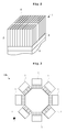
- FIG. 2 is a perspective view illustrating the radiation detector according to Embodiment 1.
- the radiation detector 1 includes a scintillator 2 configured to convert ⁇ -rays into fluorescence, and a light detector 3 configured to detect the fluorescence.
- a light guide 4 configured to transmit the fluorescence is disposed between the scintillator 2 and the light detector 3.
- the scintillator 2 has scintillation counter crystals arranged two-dimensionally.
- Each of the scintillation counter crystals C is composed of Ce-doped Lu 2(1-x) Y 2x SiO 5 (hereinafter referred to as LYSO).
- the light detector 3 allows determination of an occurrence position of fluorescence about which scintillation counter crystal emits fluorescence as well as about intensity of the fluorescence and time when the fluorescence is generated.
- the radiation detector 1 determines energy of the detected ⁇ -rays from the intensity of the fluorescence, thereby allowing output of data on the energy.
- the scintillator 2 having the configuration of Embodiment 1 is only exemplification of an aspect that may be adopted. Consequently, the configuration of the present invention is not limited to this.
- a plurality of radiation detectors 1 is arranged in a virtual circle on a plane orthogonal to the z-direction to form a unit ring 12b.
- a plurality of unit rings 12b is arranged in the central-axis direction (z-direction) to form the detector ring 12.
- a clock 19 sends time information with serial numbers to a coincidence unit 21.
- a control information setting unit 23 sends information (control information) on control of the coincidence unit 21 to the coincidence unit 21.
- the coincidence unit 21 is to operate in accordance with the control information.
- the control information is a set value, such as a time window and an energy window, referred to upon determination of the coincidence property.
- the coincidence unit 21 corresponds to the coincidence device in the present invention.
- the control information setting unit 23 corresponds to the control information setting device in the present invention.
- a radiation pulse calculating unit 20 identifies a position where the detector ring 12 detected ⁇ -rays. Then, information on the detected position identified by the radiation pulse calculating unit 20 is sent to the coincidence unit 21. The radiation pulse calculating unit 20 obtains energy of incident ⁇ -rays in addition to the detected position.
- the coincidence unit 21 receives detected data from the radiation pulse calculating unit 20. It is conceivable that two ⁇ -rays entering in the detector ring 12 coincidently is an annihilation ⁇ -ray pair derived from the radiopharmaceutical in the subject.
- the coincidence unit 21 counts frequency of detecting the annihilation gamma-ray pair entering coincidently for every combination of two scintillation counter crystals constituting the detector ring 12, and the resultant is sent to a coincidence data holder 22. Counting the number of ⁇ -rays entering coincidently is referred to as coincidence.
- the coincidence unit 21 uses the time information that the clock 19 gives to the detected data for determining the coincident property of the detected data. In such manner, the coincidence unit 21 counts the number of coincidence events that radiation enters coincidently into two of the radiation detectors 1 constituting the detector ring 12.
- the radiation pulse calculating unit 20 is constituted by radiation pulse calculating modules 20a provided in the radiation detectors 1, respectively.
- the radiation detectors 1 constitute the detector ring 12.
- the radiation pulse calculating modules 20a are connected to the radiation detectors 1 in a one-to-one manner. Accordingly, the radiation pulse calculating modules 20a are prepared to all the radiation detectors.
- each of the radiation pulse calculating modules 20a stores data (positional detector data) representing a position of the radiation detector corresponding to the radiation pulse calculating module 20a in the detector ring 12.
- the radiation pulse calculating modules 20a each store different types of detector positional data. This is because the radiation detectors 1 are located in different positions in the detector ring 12.
- the coincidence unit 21 is constituted by coincidence modules 21a each provided in the radiation pulse calculating modules 20a respectively.
- the coincidence modules 21a are connected to the radiation pulse calculating modules 20a in a one-to-one manner. Accordingly, the coincidence modules 21a are connected to all the radiation detectors 1 in a one-to-one manner. That is, one module 21a obtains detected data from one radiation detector corresponding thereto (specifically, detected data is obtained through one radiation pulse calculating module 20a). Moreover, another coincidence module 21a obtains detected data from another radiation detector corresponding thereto (specifically, detected data is obtained through another radiation pulse calculating module 20a).
- the coincidence module 21a corresponds to the module in the present invention.
- the radiation detector 1 When detecting ⁇ -rays, the radiation detector 1 sends original signals concerning ⁇ -ray detection to the corresponding radiation pulse calculating module 20a.
- the radiation pulse calculating module 20a identifies an incident position in the radiation detector 1 where the ⁇ -rays enter in accordance with the original signals. Thereafter, the radiation pulse calculating module 20a identifies which position in the detector ring 12 corresponds to the presently identified incident position. The position in the detector ring 12 is identified with the detector positional data. Finally, the radiation pulse calculating module 20a outputs the detected data to the coincidence unit 21.
- the coincidence module 21a When receiving the detected data from the radiation pulse calculating module 20a corresponding to the coincidence module 21a, the coincidence module 21a applies time information with reference to time information from the clock 19. Thereafter, coincidence is performed with the detected data to which the time information has been applied.
- the coincidence module 21a is also connected to another coincidence module 21a, and accordingly, the detected data with the applied time information is sent to the other coincidence module 21a. In such manner, the coincidence modules 21a each send and receive the detected data to and from one another, thereby sharing the detected data and performing coincidence.
- Figure 5 illustrates sending and receiving of the detected data among the coincidence modules 21a.
- the coincidence unit 21 is constituted by four coincidence modules 21a.
- Figure 5 illustrates on the left thereof four coincidence module Ma, Mb, Mc, Md based on the positions of the radiation detectors.
- the coincidence modules Ma, Mb, Mc, Md are each arranged clockwisely.
- the coincidence modules Ma, Mb, Mc, and Md send the detected data clockwisely.
- the coincidence module Ma sends the detected data to the coincidence module Mb
- the coincidence module Mb sends the detected data to the coincidence module Mc.
- the coincidence module Mc sends the detected data to the coincidence module Md
- the coincidence module Md sends the detected data to the coincidence module Ma.
- clockwise sending is performed for expediency of explanation. Alternatively, counterclockwise sending may be performed.
- Figure 5 on the right thereof illustrates the coincidence modules Ma, Mb, Mc, and Md having received the detected data from the corresponding radiation pulse calculating modules 20a.
- sending and receiving of the detected data is not performed among the coincidence modules in this state.
- the detected data that the coincidence module Ma receives from the radiation pulse calculating module 20a is expressed as detected data Da
- the detected data that the coincidence module Mb receives from the radiation pulse calculating module 20a is expressed as detected data Db
- the detected data that the coincidence module Mc receives from the radiation pulse calculating module 20a is expressed as detected data Dc
- the detected data that the coincidence module Md receives from the radiation pulse calculating module 20a is expressed as detected data Dd.
- Figure 6 illustrates sending and receiving the detected data Da, Db, Dc, Dd of the detected data among the coincidence modules Ma, Mb, Mc, Md.
- the coincidence module Ma sends the detected data Da to the coincidence module Mb
- the coincidence module Mb sends the detected data Db to the coincidence module Mc.
- the coincidence module Mc sends the detected data Dc to the coincidence module Md
- the coincidence module Md sends the detected data Dd to the coincidence module Ma.
- the coincidence module Ma holds the detected data Da besides the detected data Dd from the coincidence module Md. Consequently, the coincidence module Ma allows performing coincidence to the detected data Dd, Da. This achieves counting the number of annihilation ⁇ -ray pairs entering in two radiation detectors corresponding to the coincidence modules Md, Ma.
- the coincidence module Mb holds the detected data Db besides the detected data Da from the coincidence module Ma.
- the coincidence module Mc holds the detected data Dc besides the detected data Db from the coincidence module Mb.
- the coincidence module Md holds the detected data Dd besides the detected data Dc from the coincidence module Mc.
- the coincidence module Mb allows performing coincidence to the detected data Da, Db
- the coincidence module Mc allows performing coincidence to the detected data Db, Dc
- the coincidence module Md allows performing coincidence to the detected data Dc, Dd.
- the coincidence module Ma sends the detected data Dd to the coincidence module Mb, and the coincidence module Mb sends the detected data Da to the coincidence module Mc. Then, the coincidence module Mc sends the detected data Db to the coincidence module Md, and the coincidence module Md sends the detected data Dc to the coincidence module Ma.
- the coincidence module Ma holds the detected data Da besides the detected data Dc from the coincidence module Md. Consequently, the coincidence module Ma allows performing coincidence to the detected data Da, Dc. This achieves counting the number of annihilation ⁇ -ray pairs entering in two radiation detectors corresponding to the coincidence modules Ma, Mc.
- the coincidence module Mb holds the detected data Db besides the detected data Dd from the coincidence module Ma.
- the coincidence module Mc holds the detected data Dc besides the detected data Da from the coincidence module Mb.
- the coincidence module Md holds the detected data Dd besides the detected data Db from the coincidence module Mc.
- the coincidence module Mb allows performing coincidence to the detected data Db, Db
- the coincidence module Mc allows performing coincidence to the detected data Da, Dc
- the coincidence module Md allows performing coincidence to the detected data Db, Dd.
- one module sends the detected data to another module, the one and the other modules corresponding to the adjacent radiation detectors 1 in the detector ring 12. Similarly, such sending and receiving is repeatedly performed. As a result, the detected data received from a radiation detector corresponding to a module is sent to a module corresponding to a radiation detector located half the detector ring away. This allows performing coincidence to every combination of the radiation detectors. At this time, sending and receiving is performed between the coincidence modules Ma, Mb, Mc, and Md adjacent to each other. Moreover, one-way and chained sending of the detected data is performed so as the detected data not to be sent to its source coincidence module.
- the coincidence modules adjacent to each other mean coincidence modules corresponding to adjacent radiation detectors 1.
- the coincidence modules 21a each send the coincidence data to the coincidence data holder 22.
- An image generating section 25 obtains the tomographic image D of the subject M in accordance with the coincidence data held in the coincidence data holder 22.
- the clock 19 Upon sending the time information to the coincidence unit 21, the clock 19 sends the time information to all the coincidence modules 21a collectively. Consequently, the coincidence modules 21a each ensure to recognize current time. Moreover, the coincidence modules 21a sends the obtained time information to the radiation pulse calculating modules 20a respectively corresponding to the coincidence modules 21a.
- the radiation pulse calculating modules 20a operate in accordance with the time information.
- control information setting unit 23 sends the control information to all the coincidence module 21a collectively. This ensures to control operation of the coincidence modules 21a.
- the radiation tomography apparatus 9 includes a main controller 41 configured to control each section en bloc, and a display unit 36 configured to display configured to display a radiation tomographic image.
- the main controller 41 has a CPU, and provides each section 16, 19, 20, 21, 23, 25 by executing various programs.
- the each section may be divided into a control device assigned to the section.
- a console 35 inputs operation by an operator to each section 16, 19, 20, 21, 23, and 25.
- the subject M is inserted into the detector ring 12 to conduct an inspection with the construction of Embodiment 1. Then, detection of an annihilation gamma-ray pair emitted from the subject M starts. From this time, the coincidence modules 21a start transferring the detected data mutually. The coincidence module 21a sends to another coincidence module 21a the detected data obtained from radiation pulse calculating module 20a by itself and the detected data received from another coincidence module 21a. The coincidence module 21a performs coincidence along with such operation. Then, the image generating section 25 obtains a tomographic image representing radiopharmaceutical distribution within the subject in accordance with the coincidence data generated by the coincidence unit 21. The display unit 36 displays the tomographic image, and an inspection is completed.
- the radiation tomography apparatus 9 includes a plurality of coincidence modules 21a receiving the detected data from different radiation detectors 1.
- the coincidence modules 21a each send and receive the detected data to and from one another, thereby sharing the detected data and counting the number of coincidence events. That is, a plurality of coincidence modules 21a cooperates to function as the coincidence unit 21 counting the number of coincidence events.
- a plurality of coincidence modules 21a cooperates to function as the coincidence unit 21 counting the number of coincidence events.
- merely wiring the coincidence modules 21a achieves implementation of the coincidence unit 21. This allows manufacture of the radiation tomography apparatus 9 without new development of the substrate for coincidence. Consequently, the radiation tomography apparatus 9 of low costs can be provided with suppressed costs of the development.
- the coincidence modules 21a are provided in the radiation detectors 1 respectively so as to correspond to the radiation detectors 1 in a one-to-one manner. This ensures to divide a function of the coincidence device 21.
- Each of the coincidence modules 21a determines the coincidence property of the detected data in accordance with the time information received from the clock 19 collectively. This allows performing coincidence in accordance with the time information with more accuracy.
- the coincidence modules 21a operate in accordance with the control information received from the control information setting unit 23 collectively. This allows immediate reflection of changing the control information to the coincidence unit 21.
- the above construction is a more concrete construction of the radiation tomography apparatus 9 according to the embodiment of the present invention.
- the detected data received from one radiation detector 1 corresponding to one coincidence module 21a is sent to one coincidence module 21a corresponding to a radiation detector 1 located half the detector ring 12 away. This allows more accurate performance of coincidence to the modules.
- the present invention is not limited to the above construction, but may be modified as under.
- the present invention is suitable for a radiation tomography apparatus for medical use.
Landscapes
- Health & Medical Sciences (AREA)
- Life Sciences & Earth Sciences (AREA)
- Physics & Mathematics (AREA)
- High Energy & Nuclear Physics (AREA)
- Molecular Biology (AREA)
- Medical Informatics (AREA)
- Engineering & Computer Science (AREA)
- General Physics & Mathematics (AREA)
- Spectroscopy & Molecular Physics (AREA)
- Nuclear Medicine, Radiotherapy & Molecular Imaging (AREA)
- Biomedical Technology (AREA)
- Optics & Photonics (AREA)
- General Health & Medical Sciences (AREA)
- Surgery (AREA)
- Radiology & Medical Imaging (AREA)
- Heart & Thoracic Surgery (AREA)
- Biophysics (AREA)
- Animal Behavior & Ethology (AREA)
- Pathology (AREA)
- Public Health (AREA)
- Veterinary Medicine (AREA)
- Nuclear Medicine (AREA)
- Measurement Of Radiation (AREA)
Abstract
Description
- The present invention relates to a radiation tomography apparatus that images radiation emitted from a subject. In particular, the present invention is directed to a radiation tomography apparatus that generates a tomographic image through performing coincidence.
- Description will be given of a concrete construction of a conventional radiation tomography apparatus. As illustrated in
Figure 7 , a conventionalradiation tomography apparatus 50 includes atop board 52 configured to support a subject M placed thereon, and adetector ring 62 configured to detect annihilation radiation pairs. Thedetector ring 62 has an opening into which the subject M is insertable together with thetop board 52. - When the conventional
radiation tomography apparatus 50 is used to determine radiopharmaceutical distribution in the subject M, the subject M is moved inside the opening of thedetector ring 62. Thereafter, positions of occurrence of annihilation radiation-pairs emitted from the subject M are imaged, whereby a radiation tomographic image is obtained. Such a radiation tomography apparatus is referred to as a PET - (positron emission tomography) apparatus. The PET apparatus identifies occurrence status of the annihilation radiation-pairs by counting the number of coincidence events, thereby obtaining a tomographic image. Here, the coincidence event represents detection of two rays of radiation at different positions in the
detector ring 62. - The
detector ring 62 has radiation detectors arranged annularly. Consequently, an annihilation radiation-pair is detected coincidently with different radiation detectors. Each of the radiation detectors cannot determine whether or not the detected radiation is derived from the annihilation radiation-pair. Accordingly, the conventional construction transmits the detected data received from the radiation detectors to onesubstrate 63. SeeFigure 8 . Thesubstrate 63 receives the detected data from all the radiation detectors constituting thedetector ring 62. Thesubstrate 63 finds two pieces of the detected data having coincident detection time. In such manner, one coincidence event is to be found. - The
substrate 63 successively finds coincidence events through checking the detected data, and counts the number of coincidence events. The number of coincidence events obtained in such manner is used for generating a tomographic image. See, for example, Japanese Patent Publication No.2008-190901A -
Patent Literature 1 Japanese Patent Publication No.2008-190901A - However, the conventional construction has the following drawback. Specifically, the conventional construction has difficulty in changing an apparatus design. As illustrated in
Figure 8 , the conventional construction includes onesubstrate 63 for thedetector ring 62, thesubstrate 63 counting the number of coincidence events. The number of radiation detectors constituting thedetector ring 62 is variable depending on purposes of the apparatus. For instance, a radiation tomography apparatus for imaging a whole body of a subject includes adetector ring 62 with approximately one hundred radiation detectors being arranged annularly. Moreover, a radiation tomography apparatus for animal experiment includes adetector ring 62 with approximately eight radiation detectors being arranged annularly. - The conventional construction needs to prepare one
substrate 63 for counting the number of coincidence events for thedetector ring 62. Consequently, upon development of a new radiation tomography apparatus, it may be necessary to redesign thesubstrate 63 for counting the number of coincidence events. It is assumed, for example, that a new radiation tomography apparatus is to be developed having the detector ring constituted by fifty radiation detectors arranged annularly. In addition, it is also assumed that such the detector ring has not been manufactured. The conventional construction needs to prepare anew substrate 63 that allows counting the number of coincidence events in the fifty radiation detectors. This is because nosubstrate 63 corresponding to such the detector ring has been designed yet. - In other words, with the conventional construction, the
substrates 63 adaptable to the number of radiation detectors may be necessarily produced newly upon the development of the radiation tomography apparatus. Such the circumstance contributes to increase in cost of the development of the radiation tomography apparatus. - The present invention has been made regarding the state of the art noted above, and its one object is to provide a radiation tomography apparatus of a low price that facilitates a design change of a detector ring to suppress costs of development.
- The present invention adopts the following construction for overcoming the above drawback. That is, one aspect of the present invention discloses a radiation tomography apparatus including a plurality of radiation detectors, and a plurality of modules. The modules are connected to the radiation detectors respectively, and are connected to one another to send and receive detected data outputted from the radiation detectors mutually, thereby sharing the detected data and counting the number of coincidence events.
- The radiation tomography apparatus according to the aspect of the present invention includes a plurality of modules configured to receive the detected data from the different radiation detectors. Then, the modules each send and receive the detected data mutually, thereby sharing the detected data and counting the number of coincidence events. In other words, a plurality of modules cooperates to function as a coincidence device that counts the number of coincidence events. That is, when manufacturing radiation tomography apparatus, merely wiring the coincidence modules achieves implementation of the coincidence unit. This allows manufacturing the radiation tomography apparatus without new development of the substrate for performing coincidence. Consequently, the radiation tomography apparatus of a low price can be provided with suppressed costs of the development.
- Moreover, it is more desirable that the modules of the radiation tomography apparatus are provided in the radiation detectors respectively.
- The above construction is a more detailed construction of the radiation tomography apparatus according to the present invention. The modules are provided in the radiation detectors respectively so as to correspond to the radiation detectors in a one-to-one manner. This ensures to divide a function of the coincidence device.
- Moreover, the radiation tomography apparatus further includes a clock configured to send time information to the modules collectively, and the modules determine a coincidence property of the detected data in accordance with the time information received from the clock. Such is more desirable.
- The above construction is a more detailed construction of the radiation tomography apparatus according to the present invention. Each of the modules determines the coincidence property of the detected data in accordance with the time information received from the clock. This allows performance coincidence accurately in accordance with the time information with more accuracy.
- Moreover, the radiation tomography apparatus includes a control information setting device configured to send control information on coincidence to each of the modules collectively, and the modules operate in accordance with the control information received from the control information setting device. Such is more desirable.
- The above construction is a more detailed construction of the radiation tomography apparatus according to the present invention. The modules each operate in accordance with the control information received from the control information setting device collectively. This allows immediate reflection of changing the control information to the coincidence device.
- Moreover, in the radiation tomography apparatus, the detection data is sent from one to the other of two modules among the modules, the two modules corresponding to the radiation detectors adjacent to each other in the detector ring constituted by the radiation detectors arranged annularly, and the detected data is similarly sent and received repeatedly, whereby the detected data received from one of the radiation detector is sent to one of the modules corresponding to the radiation detector located half the detector ring away. Such is more desirable.
- The above construction is a more detailed construction of the radiation tomography apparatus according to the present invention. The detected data received from a radiation detector corresponding to a module is sent up to a module corresponding to a radiation detector located half the detector ring away. This allows more accurate performance of coincidence to the modules.
- Moreover, it is more desirable that the radiation tomography apparatus is used for whole-body subject imaging, breast imaging, or small animal imaging.
- The above construction is a more detailed construction of the radiation tomography apparatus according to the present invention. The number of radiation detectors constituting the detector ring is variable among the constructions of such the apparatus. However, the embodiment of the present invention can achieve a coincidence device by merely wiring the modules. This causes unnecessary development of a new substrate performing coincidence.
- The radiation tomography apparatus according to the embodiment of the present invention includes a plurality of modules receiving detected data from different radiation detectors, respectively. Then, the modules each send and receive the detected data mutually, thereby sharing the detected data and counting the number of coincidence events. That is, when manufacturing radiation tomography apparatus, merely wiring the coincidence modules achieves implementation of the coincidence unit. This allows manufacturing the radiation tomography apparatus without new development of the substrate for coincidence. Consequently, the radiation tomography apparatus of a low price can be provided with suppressed costs of the development.
-
-
Figure 1 is a function block diagram illustrating a radiation tomography apparatus according to one embodiment of the present invention. -
Figure 2 is a perspective view illustrating a radiation detector according to the embodiment. -
Figure 3 is a plan view illustrating a detector ring according to the embodiment. -
Figure 4 is a schematic view illustrating a coincidence unit according to the embodiment. -
Figures 5 and6 are schematic views each illustrating operation of a coincidence module according to the embodiment. -
Figure 7 is a sectional view illustrating a conventional radiation tomography apparatus. -
Figure 8 is a schematic view illustrating the conventional radiation tomography apparatus. - Description will be given of embodiments of the present invention with reference to drawings.
- Description will be given hereinunder of a
radiation tomography apparatus 9 according to one embodiment of the present invention with reference to drawings.Figure 1 is a function block diagram illustrating theradiation tomography apparatus 9 according toEmbodiment 1. Theradiation tomography apparatus 9 according toEmbodiment 1 is used for whole-body imaging. Theradiation tomography apparatus 9 includes atop board 10 configured to support a subject M placed thereon, agantry 11 with an opening through which thetop board 10 is guided in a longitudinal direction (z-direction) of thetop board 10, and adetector ring 12 in a ring shape provided inside thegantry 11 and configured to guide thetop board 10 in the z-direction. The opening of thedetector ring 12 is cylindrical extending in the z-direction (the longitudinal direction of thetop board 10, i.e., a body-axis direction of the subject M). Accordingly, thedetector ring 12 itself extends in the z-direction. Thegantry 11 has the opening sufficient for accommodating the subject M, into which the subject M is to be inserted. - The
top board 10 can pass through the opening of the gantry 11 (detector ring 12) in the z-direction, and is movable forward and backward in the z-direction. A topboard moving mechanism 15 slides thetop board 10 as above. A top board movement controller 16 controls the topboard moving mechanism 15. The top board movement controller 16 is a top board movement control device for controlling the topboard moving mechanism 15. Thetop board 10 slides from outside thedetector ring 12 in its entirety, and one end of thetop board 10 is guided into the opening of thedetector ring 12. - The
detector ring 12 is provided inside thegantry 11 for detecting annihilation γ-ray pairs emitted from the subject M. Thedetector ring 12 has a cylindrical shape extending in the body-axis direction of the subject M, and has a length of approximately 15cm to 26cm.Ring absorbers detector ring 12 in a central axis direction (z-direction). Theabsorbers detector ring 12. Theabsorbers detector ring 12. Theabsorbers detector ring 12. - Description will be given next of the
radiation detector 1 constituting thedetector ring 12.Figure 2 is a perspective view illustrating the radiation detector according toEmbodiment 1. As illustrated inFigure 2 , theradiation detector 1 includes ascintillator 2 configured to convert γ-rays into fluorescence, and alight detector 3 configured to detect the fluorescence. Moreover, alight guide 4 configured to transmit the fluorescence is disposed between thescintillator 2 and thelight detector 3. - The
scintillator 2 has scintillation counter crystals arranged two-dimensionally. Each of the scintillation counter crystals C is composed of Ce-doped Lu2(1-x)Y2xSiO5 (hereinafter referred to as LYSO). Thelight detector 3 allows determination of an occurrence position of fluorescence about which scintillation counter crystal emits fluorescence as well as about intensity of the fluorescence and time when the fluorescence is generated. Theradiation detector 1 determines energy of the detected γ-rays from the intensity of the fluorescence, thereby allowing output of data on the energy. Here, thescintillator 2 having the configuration ofEmbodiment 1 is only exemplification of an aspect that may be adopted. Consequently, the configuration of the present invention is not limited to this. - Description will be given of the
detector ring 12. As illustrated inFigure 3 ofEmbodiment 1, a plurality ofradiation detectors 1 is arranged in a virtual circle on a plane orthogonal to the z-direction to form aunit ring 12b. A plurality of unit rings 12b is arranged in the central-axis direction (z-direction) to form thedetector ring 12. - A
clock 19 sends time information with serial numbers to acoincidence unit 21. A controlinformation setting unit 23 sends information (control information) on control of thecoincidence unit 21 to thecoincidence unit 21. Thecoincidence unit 21 is to operate in accordance with the control information. The control information is a set value, such as a time window and an energy window, referred to upon determination of the coincidence property. Thecoincidence unit 21 corresponds to the coincidence device in the present invention. The controlinformation setting unit 23 corresponds to the control information setting device in the present invention. - A radiation
pulse calculating unit 20 identifies a position where thedetector ring 12 detected γ-rays. Then, information on the detected position identified by the radiationpulse calculating unit 20 is sent to thecoincidence unit 21. The radiationpulse calculating unit 20 obtains energy of incident γ-rays in addition to the detected position. - The
coincidence unit 21 receives detected data from the radiationpulse calculating unit 20. It is conceivable that two γ-rays entering in thedetector ring 12 coincidently is an annihilation γ-ray pair derived from the radiopharmaceutical in the subject. Thecoincidence unit 21 counts frequency of detecting the annihilation gamma-ray pair entering coincidently for every combination of two scintillation counter crystals constituting thedetector ring 12, and the resultant is sent to acoincidence data holder 22. Counting the number of γ-rays entering coincidently is referred to as coincidence. Here, thecoincidence unit 21 uses the time information that theclock 19 gives to the detected data for determining the coincident property of the detected data. In such manner, thecoincidence unit 21 counts the number of coincidence events that radiation enters coincidently into two of theradiation detectors 1 constituting thedetector ring 12. - Description will be given of the radiation
pulse calculating unit 20 withFigure 4 . As illustrated inFigure 4 , the radiationpulse calculating unit 20 is constituted by radiationpulse calculating modules 20a provided in theradiation detectors 1, respectively. Theradiation detectors 1 constitute thedetector ring 12. The radiationpulse calculating modules 20a are connected to theradiation detectors 1 in a one-to-one manner. Accordingly, the radiationpulse calculating modules 20a are prepared to all the radiation detectors. In addition, each of the radiationpulse calculating modules 20a stores data (positional detector data) representing a position of the radiation detector corresponding to the radiationpulse calculating module 20a in thedetector ring 12. The radiationpulse calculating modules 20a each store different types of detector positional data. This is because theradiation detectors 1 are located in different positions in thedetector ring 12. - Description will be given next of the
coincidence unit 21 withFigure 4 . As illustrated inFigure 4 , thecoincidence unit 21 is constituted bycoincidence modules 21a each provided in the radiationpulse calculating modules 20a respectively. Thecoincidence modules 21a are connected to the radiationpulse calculating modules 20a in a one-to-one manner. Accordingly, thecoincidence modules 21a are connected to all theradiation detectors 1 in a one-to-one manner. That is, onemodule 21a obtains detected data from one radiation detector corresponding thereto (specifically, detected data is obtained through one radiationpulse calculating module 20a). Moreover, anothercoincidence module 21a obtains detected data from another radiation detector corresponding thereto (specifically, detected data is obtained through another radiationpulse calculating module 20a). Thecoincidence module 21a corresponds to the module in the present invention. - Description will be given of operation of the
position identifying unit 20. When detecting γ-rays, theradiation detector 1 sends original signals concerning γ-ray detection to the corresponding radiationpulse calculating module 20a. The radiationpulse calculating module 20a identifies an incident position in theradiation detector 1 where the γ-rays enter in accordance with the original signals. Thereafter, the radiationpulse calculating module 20a identifies which position in thedetector ring 12 corresponds to the presently identified incident position. The position in thedetector ring 12 is identified with the detector positional data. Finally, the radiationpulse calculating module 20a outputs the detected data to thecoincidence unit 21. - Description will be given next of operation of the
coincidence unit 21. When receiving the detected data from the radiationpulse calculating module 20a corresponding to thecoincidence module 21a, thecoincidence module 21a applies time information with reference to time information from theclock 19. Thereafter, coincidence is performed with the detected data to which the time information has been applied. - The
coincidence module 21a is also connected to anothercoincidence module 21a, and accordingly, the detected data with the applied time information is sent to theother coincidence module 21a. In such manner, thecoincidence modules 21a each send and receive the detected data to and from one another, thereby sharing the detected data and performing coincidence. -
Figure 5 illustrates sending and receiving of the detected data among thecoincidence modules 21a. For simple explanation, it is assumed that thecoincidence unit 21 is constituted by fourcoincidence modules 21a.Figure 5 illustrates on the left thereof four coincidence module Ma, Mb, Mc, Md based on the positions of the radiation detectors. InFigure 5 , the coincidence modules Ma, Mb, Mc, Md are each arranged clockwisely. - Description will be given of operation of the coincidence modules Ma, Mb, Mc, and Md. As illustrated in
Figure 5 on the left thereof, the coincidence modules Ma, Mb, Mc, and Md send the detected data clockwisely. Specifically, the coincidence module Ma sends the detected data to the coincidence module Mb, and the coincidence module Mb sends the detected data to the coincidence module Mc. Then, the coincidence module Mc sends the detected data to the coincidence module Md, and the coincidence module Md sends the detected data to the coincidence module Ma. Here, clockwise sending is performed for expediency of explanation. Alternatively, counterclockwise sending may be performed. -
Figure 5 on the right thereof illustrates the coincidence modules Ma, Mb, Mc, and Md having received the detected data from the corresponding radiationpulse calculating modules 20a. In other words, sending and receiving of the detected data is not performed among the coincidence modules in this state. Here, the detected data that the coincidence module Ma receives from the radiationpulse calculating module 20a is expressed as detected data Da, the detected data that the coincidence module Mb receives from the radiationpulse calculating module 20a is expressed as detected data Db. Moreover, the detected data that the coincidence module Mc receives from the radiationpulse calculating module 20a is expressed as detected data Dc, and the detected data that the coincidence module Md receives from the radiationpulse calculating module 20a is expressed as detected data Dd. -
Figure 6 illustrates sending and receiving the detected data Da, Db, Dc, Dd of the detected data among the coincidence modules Ma, Mb, Mc, Md. Firstly, as illustrated on the left ofFigure 6 , the coincidence module Ma sends the detected data Da to the coincidence module Mb, and the coincidence module Mb sends the detected data Db to the coincidence module Mc. Then, the coincidence module Mc sends the detected data Dc to the coincidence module Md, and the coincidence module Md sends the detected data Dd to the coincidence module Ma. - At the time when such sending has been performed (see the left of
Figure 6 ), the coincidence module Ma holds the detected data Da besides the detected data Dd from the coincidence module Md. Consequently, the coincidence module Ma allows performing coincidence to the detected data Dd, Da. This achieves counting the number of annihilation γ-ray pairs entering in two radiation detectors corresponding to the coincidence modules Md, Ma. - Similarly, at the time when such sending has been performed (see the left of
Figure 6 ), the coincidence module Mb holds the detected data Db besides the detected data Da from the coincidence module Ma. In addition, the coincidence module Mc holds the detected data Dc besides the detected data Db from the coincidence module Mb. The coincidence module Md holds the detected data Dd besides the detected data Dc from the coincidence module Mc. - Accordingly, at the time when such sending has been performed (see the left of
Figure 6 ), the coincidence module Mb allows performing coincidence to the detected data Da, Db, and the coincidence module Mc allows performing coincidence to the detected data Db, Dc. Moreover, the coincidence module Md allows performing coincidence to the detected data Dc, Dd. - Thereafter, as illustrated in the right of
Figure 6 , the coincidence module Ma sends the detected data Dd to the coincidence module Mb, and the coincidence module Mb sends the detected data Da to the coincidence module Mc. Then, the coincidence module Mc sends the detected data Db to the coincidence module Md, and the coincidence module Md sends the detected data Dc to the coincidence module Ma. - At the time illustrated in the left of
Figure 6 , the coincidence module Ma holds the detected data Da besides the detected data Dc from the coincidence module Md. Consequently, the coincidence module Ma allows performing coincidence to the detected data Da, Dc. This achieves counting the number of annihilation γ-ray pairs entering in two radiation detectors corresponding to the coincidence modules Ma, Mc. - Similarly, at the time illustrated in the right of
Figure 6 , the coincidence module Mb holds the detected data Db besides the detected data Dd from the coincidence module Ma. In addition, the coincidence module Mc holds the detected data Dc besides the detected data Da from the coincidence module Mb. The coincidence module Md holds the detected data Dd besides the detected data Db from the coincidence module Mc. - Accordingly, at the time illustrated in the right of
Figure 6 , the coincidence module Mb allows performing coincidence to the detected data Db, Db, and the coincidence module Mc allows performing coincidence to the detected data Da, Dc. Moreover, the coincidence module Md allows performing coincidence to the detected data Db, Dd. - As noted above, among the coincidence modules Ma, Mb, Mc, and Md, one module sends the detected data to another module, the one and the other modules corresponding to the
adjacent radiation detectors 1 in thedetector ring 12. Similarly, such sending and receiving is repeatedly performed. As a result, the detected data received from a radiation detector corresponding to a module is sent to a module corresponding to a radiation detector located half the detector ring away. This allows performing coincidence to every combination of the radiation detectors. At this time, sending and receiving is performed between the coincidence modules Ma, Mb, Mc, and Md adjacent to each other. Moreover, one-way and chained sending of the detected data is performed so as the detected data not to be sent to its source coincidence module. Here, the coincidence modules adjacent to each other mean coincidence modules corresponding toadjacent radiation detectors 1. - The
coincidence modules 21a each send the coincidence data to thecoincidence data holder 22. Animage generating section 25 obtains the tomographic image D of the subject M in accordance with the coincidence data held in thecoincidence data holder 22. - Description will be given next of operation of the
clock 19. Upon sending the time information to thecoincidence unit 21, theclock 19 sends the time information to all thecoincidence modules 21a collectively. Consequently, thecoincidence modules 21a each ensure to recognize current time. Moreover, thecoincidence modules 21a sends the obtained time information to the radiationpulse calculating modules 20a respectively corresponding to thecoincidence modules 21a. The radiationpulse calculating modules 20a operate in accordance with the time information. - Similarly, upon sending the control information to the
coincidence unit 21, the controlinformation setting unit 23 sends the control information to all thecoincidence module 21a collectively. This ensures to control operation of thecoincidence modules 21a. - The
radiation tomography apparatus 9 includes amain controller 41 configured to control each section en bloc, and adisplay unit 36 configured to display configured to display a radiation tomographic image. Themain controller 41 has a CPU, and provides eachsection console 35 inputs operation by an operator to eachsection - Description will be given next of operation of the radiation tomography apparatus. As illustrated in
Figure 1 , the subject M is inserted into thedetector ring 12 to conduct an inspection with the construction ofEmbodiment 1. Then, detection of an annihilation gamma-ray pair emitted from the subject M starts. From this time, thecoincidence modules 21a start transferring the detected data mutually. Thecoincidence module 21a sends to anothercoincidence module 21a the detected data obtained from radiationpulse calculating module 20a by itself and the detected data received from anothercoincidence module 21a. Thecoincidence module 21a performs coincidence along with such operation. Then, theimage generating section 25 obtains a tomographic image representing radiopharmaceutical distribution within the subject in accordance with the coincidence data generated by thecoincidence unit 21. Thedisplay unit 36 displays the tomographic image, and an inspection is completed. - As noted above, the
radiation tomography apparatus 9 according to the embodiment of the present invention includes a plurality ofcoincidence modules 21a receiving the detected data fromdifferent radiation detectors 1. Thecoincidence modules 21a each send and receive the detected data to and from one another, thereby sharing the detected data and counting the number of coincidence events. That is, a plurality ofcoincidence modules 21a cooperates to function as thecoincidence unit 21 counting the number of coincidence events. In other words, when manufacturingradiation tomography apparatus 9, merely wiring thecoincidence modules 21a achieves implementation of thecoincidence unit 21. This allows manufacture of theradiation tomography apparatus 9 without new development of the substrate for coincidence. Consequently, theradiation tomography apparatus 9 of low costs can be provided with suppressed costs of the development. - Moreover, the
coincidence modules 21a are provided in theradiation detectors 1 respectively so as to correspond to theradiation detectors 1 in a one-to-one manner. This ensures to divide a function of thecoincidence device 21. - Each of the
coincidence modules 21a determines the coincidence property of the detected data in accordance with the time information received from theclock 19 collectively. This allows performing coincidence in accordance with the time information with more accuracy. - Moreover, in the above embodiment, the
coincidence modules 21a operate in accordance with the control information received from the controlinformation setting unit 23 collectively. This allows immediate reflection of changing the control information to thecoincidence unit 21. - The above construction is a more concrete construction of the
radiation tomography apparatus 9 according to the embodiment of the present invention. The detected data received from oneradiation detector 1 corresponding to onecoincidence module 21a is sent to onecoincidence module 21a corresponding to aradiation detector 1 located half thedetector ring 12 away. This allows more accurate performance of coincidence to the modules. - The present invention is not limited to the above construction, but may be modified as under.
-
- (1) The above construction is an apparatus for imaging a whole body of a subject. However, the present invention is limited to such the construction. The present invention is applicable to an apparatus for imaging a head of a subject, or an apparatus for breast imaging. Moreover, the present invention is applicable to an apparatus for imaging small animals. The number of radiation detectors constituting the detector ring is variable among the constructions of such the apparatus. However, the embodiment of the present invention can achieve a coincidence device by merely wiring the modules. This causes unnecessary development of a new substrate that performs coincidence.
- (2) In the above construction, the
radiation detectors 1 correspond to thecoincidence modules 21a respectively. However, the present invention is not limited to the construction. Alternatively, a plurality of (e.g., two)radiation detectors 1 correspond to thecoincidence module 21a. Theradiation tomography apparatus 9 may have such a construction. In this case, the radiationpulse calculating modules 20a may correspond to theradiation detectors 1 in a one-to-one manner or to thecoincidence modules 21a in a one-to-one manner. Especially, with the apparatus having a plurality of unit detector rings 12a, a plurality ofradiation detectors 1 laminated in the z-direction may be assigned to onecoincidence module 21a. - (3) In each of the foregoing embodiments, the scintillation counter crystal is composed of LYSO. Alternatively, the scintillation counter crystal may be composed of other materials, such as LGSO (Lu2(1-X)G2XSiO5) or GSO (Gd2SiO5). According to this modification, a method of manufacturing a radiation detector may be provided that allows provision of a radiation detector of a low price.
- (4) The optical detector in each of the foregoing embodiments is constituted by a photomultiplier tube. However, the present invention is not limited to this. A photodiode, an avalanche photodiode, a semiconductor detector, or the like may be used instead of the photomultiplier tube.
- As described above, the present invention is suitable for a radiation tomography apparatus for medical use.
-
- 1
- radiation detector
- 12
- detector ring
- 19
- clock
- 21
- coincidence unit (coincidence device)
- 21a
- coincidence module (module)
- 23
- control information setting unit (control information setting device)
Claims (6)
- A radiation tomography apparatus, comprising:a plurality of radiation detectors; anda plurality of modules, whereinthe modules are connected to the radiation detectors respectively, and are connected to one another, andthe modules send and receive detected data outputted from the radiation detectors mutually, thereby sharing the detected data and counting the number of coincidence events.
- The radiation tomography apparatus according to claim 1, wherein
the modules are provided in the radiation detectors respectively. - The radiation tomography apparatus according to claim 1 or 2, further comprising:a clock configured to send time information to the modules collectively, whereinthe modules determine a coincidence property of the detected data in accordance with the time information received from the clock.
- The radiation tomography apparatus according to any of claims 1 to 3, further comprising:a control information setting device configured to send control information on coincidence to each of the modules collectively, whereinthe modules operate in accordance with the control information received from the control information setting device.
- The radiation tomography apparatus according to any of claims 1 to 4,
wherein
the detection data is sent from one to the other of two modules among the modules , the two modules corresponding to the radiation detectors adjacent to each other in the detector ring constituted by the radiation detectors arranged annularly, and the detected data is similarly sent and received repeatedly, whereby the detected data received from one of the radiation detector is sent to one of the modulecorresponding to the radiation detector located half the detector ring away. - The radiation tomography apparatus according to any of claims 1 to 5,
wherein
the radiation tomography apparatus is used for imaging a whole-body of the subject, for imaging a head of the subject, for breast imaging, or for small animal imaging.
Applications Claiming Priority (1)
| Application Number | Priority Date | Filing Date | Title |
|---|---|---|---|
| PCT/JP2011/005352 WO2013042173A1 (en) | 2011-09-22 | 2011-09-22 | Tomography device |
Publications (2)
| Publication Number | Publication Date |
|---|---|
| EP2759850A1 true EP2759850A1 (en) | 2014-07-30 |
| EP2759850A4 EP2759850A4 (en) | 2015-04-01 |
Family
ID=47913990
Family Applications (1)
| Application Number | Title | Priority Date | Filing Date |
|---|---|---|---|
| EP11872804.7A Withdrawn EP2759850A4 (en) | 2011-09-22 | 2011-09-22 | Tomography device |
Country Status (6)
| Country | Link |
|---|---|
| US (1) | US9086491B2 (en) |
| EP (1) | EP2759850A4 (en) |
| JP (1) | JP5725190B2 (en) |
| CN (1) | CN103782196B (en) |
| TW (1) | TWI505817B (en) |
| WO (1) | WO2013042173A1 (en) |
Family Cites Families (12)
| Publication number | Priority date | Publication date | Assignee | Title |
|---|---|---|---|---|
| US5241181A (en) * | 1992-07-27 | 1993-08-31 | General Electric Company | Coincidence detector for a PET scanner |
| JP4659962B2 (en) * | 2000-10-04 | 2011-03-30 | 株式会社東芝 | Nuclear medicine diagnostic equipment |
| WO2003098264A1 (en) * | 2002-05-15 | 2003-11-27 | Hamamatsu Photonics K.K. | Image processing system and image processing method |
| US7778787B2 (en) * | 2004-08-13 | 2010-08-17 | Koninklijke Philips Electronics N.V. | Timing calibration for TOF-PET scanner |
| JP2006090827A (en) * | 2004-09-24 | 2006-04-06 | Hitachi Ltd | Radiation inspection apparatus and timing correction method thereof |
| WO2007015198A2 (en) | 2005-08-04 | 2007-02-08 | Koninklijke Philips Electronics N.V. | Modular signal processing backbone for pet |
| CN101460864B (en) | 2006-09-19 | 2012-02-01 | 株式会社岛津制作所 | Method for determining parameters required for identification mechanism of scintillator array of nuclear medicine diagnostic apparatus |
| JP4621188B2 (en) | 2006-09-29 | 2011-01-26 | 株式会社日立製作所 | Nuclear medicine diagnostic equipment |
| US9348033B2 (en) | 2006-12-15 | 2016-05-24 | Shimadzu Corporation | Positron CT apparatus |
| JP2008190901A (en) | 2007-02-01 | 2008-08-21 | Hitachi Ltd | Positron emission tomography system |
| WO2009101677A1 (en) * | 2008-02-13 | 2009-08-20 | Shimadzu Corporation | Radiation detector and tomographic system equipped with the same |
| WO2010013356A1 (en) * | 2008-07-31 | 2010-02-04 | 株式会社島津製作所 | Radiation tomographic equipment |
-
2011
- 2011-09-22 EP EP11872804.7A patent/EP2759850A4/en not_active Withdrawn
- 2011-09-22 JP JP2013534465A patent/JP5725190B2/en active Active
- 2011-09-22 CN CN201180073368.5A patent/CN103782196B/en not_active Expired - Fee Related
- 2011-09-22 US US14/346,658 patent/US9086491B2/en not_active Expired - Fee Related
- 2011-09-22 WO PCT/JP2011/005352 patent/WO2013042173A1/en not_active Ceased
-
2012
- 2012-09-21 TW TW101134598A patent/TWI505817B/en not_active IP Right Cessation
Also Published As
| Publication number | Publication date |
|---|---|
| TW201316956A (en) | 2013-05-01 |
| CN103782196A (en) | 2014-05-07 |
| CN103782196B (en) | 2016-12-28 |
| US9086491B2 (en) | 2015-07-21 |
| US20140239184A1 (en) | 2014-08-28 |
| JP5725190B2 (en) | 2015-05-27 |
| JPWO2013042173A1 (en) | 2015-03-26 |
| TWI505817B (en) | 2015-11-01 |
| EP2759850A4 (en) | 2015-04-01 |
| WO2013042173A1 (en) | 2013-03-28 |
Similar Documents
| Publication | Publication Date | Title |
|---|---|---|
| JP6298451B2 (en) | Image processing system and image processing method | |
| RU2543544C2 (en) | Pet-detector assembly with improved assessment characteristics | |
| EP2454612B1 (en) | Strip device and method for determining the location and time of reaction of the gamma quanta and the use of the device to determine the location and time of reaction of the gamma quanta in positron emission tomography | |
| US9784850B2 (en) | Multimodal imaging apparatus | |
| JP4670991B2 (en) | Radiation detector and tomography apparatus provided with the same | |
| Lewellen | The challenge of detector designs for PET | |
| CN113274043B (en) | Radiological diagnosis device and radiological diagnosis method | |
| JP2011059099A (en) | Pet (positron emission tomography) detector element using photomultiplier tube of different size | |
| JP6545565B2 (en) | Detector, nuclear medicine imaging apparatus, PET-CT apparatus and PET-MRI apparatus | |
| US8395128B2 (en) | Radiation tomography apparatus | |
| US20160073976A1 (en) | Nuclear medicine diagnostic apparatus and nuclear medicine image generating method | |
| CN105395208A (en) | PET detection device with single photon emission computed tomography function | |
| JP2018112455A (en) | Nuclear medicine diagnosis device and calibration method | |
| CN102028484B (en) | Detector module for an emission tomography scanner | |
| JP2010101682A (en) | Nuclear medicine diagnosis apparatus | |
| US9086491B2 (en) | Radiation tomography apparatus | |
| JP7022125B2 (en) | Optical sensor signal processing method | |
| EP2392946B1 (en) | Radiation tomography apparatus | |
| US20120228511A1 (en) | Positron emission computed tomography apparatus | |
| US20120312996A1 (en) | Nuclear medicine imaging apparatus and analyzing system | |
| JP2024055098A (en) | PET device, method and program | |
| JP2024033150A (en) | Image acquisition device and image acquisition method | |
| JP2009229336A (en) | Method and device for improving sensitivity of positron image | |
| JPWO2014033785A1 (en) | Radiation tomography equipment | |
| Deng et al. | Conceptual design of a combined CLI/PET scanner via all event-by-event readout |
Legal Events
| Date | Code | Title | Description |
|---|---|---|---|
| PUAI | Public reference made under article 153(3) epc to a published international application that has entered the european phase |
Free format text: ORIGINAL CODE: 0009012 |
|
| 17P | Request for examination filed |
Effective date: 20140324 |
|
| AK | Designated contracting states |
Kind code of ref document: A1 Designated state(s): AL AT BE BG CH CY CZ DE DK EE ES FI FR GB GR HR HU IE IS IT LI LT LU LV MC MK MT NL NO PL PT RO RS SE SI SK SM TR |
|
| DAX | Request for extension of the european patent (deleted) | ||
| A4 | Supplementary search report drawn up and despatched |
Effective date: 20150227 |
|
| GRAP | Despatch of communication of intention to grant a patent |
Free format text: ORIGINAL CODE: EPIDOSNIGR1 |
|
| RIC1 | Information provided on ipc code assigned before grant |
Ipc: A61B 6/03 20060101AFI20180531BHEP Ipc: G01T 1/29 20060101ALI20180531BHEP |
|
| INTG | Intention to grant announced |
Effective date: 20180619 |
|
| STAA | Information on the status of an ep patent application or granted ep patent |
Free format text: STATUS: THE APPLICATION IS DEEMED TO BE WITHDRAWN |
|
| 18D | Application deemed to be withdrawn |
Effective date: 20181030 |