EP2759668A1 - Door hinge assembly - Google Patents
Door hinge assembly Download PDFInfo
- Publication number
- EP2759668A1 EP2759668A1 EP14165930.0A EP14165930A EP2759668A1 EP 2759668 A1 EP2759668 A1 EP 2759668A1 EP 14165930 A EP14165930 A EP 14165930A EP 2759668 A1 EP2759668 A1 EP 2759668A1
- Authority
- EP
- European Patent Office
- Prior art keywords
- housing
- hinge assembly
- mounting member
- opening
- abutting portion
- Prior art date
- Legal status (The legal status is an assumption and is not a legal conclusion. Google has not performed a legal analysis and makes no representation as to the accuracy of the status listed.)
- Withdrawn
Links
Images



Classifications
-
- E—FIXED CONSTRUCTIONS
- E05—LOCKS; KEYS; WINDOW OR DOOR FITTINGS; SAFES
- E05F—DEVICES FOR MOVING WINGS INTO OPEN OR CLOSED POSITION; CHECKS FOR WINGS; WING FITTINGS NOT OTHERWISE PROVIDED FOR, CONCERNED WITH THE FUNCTIONING OF THE WING
- E05F1/00—Closers or openers for wings, not otherwise provided for in this subclass
- E05F1/08—Closers or openers for wings, not otherwise provided for in this subclass spring-actuated, e.g. for horizontally sliding wings
- E05F1/10—Closers or openers for wings, not otherwise provided for in this subclass spring-actuated, e.g. for horizontally sliding wings for swinging wings, e.g. counterbalance
- E05F1/12—Mechanisms in the shape of hinges or pivots, operated by springs
- E05F1/1246—Mechanisms in the shape of hinges or pivots, operated by springs with a coil spring perpendicular to the pivot axis
- E05F1/1253—Mechanisms in the shape of hinges or pivots, operated by springs with a coil spring perpendicular to the pivot axis with a compression spring
- E05F1/1261—Mechanisms in the shape of hinges or pivots, operated by springs with a coil spring perpendicular to the pivot axis with a compression spring for counterbalancing
-
- E—FIXED CONSTRUCTIONS
- E05—LOCKS; KEYS; WINDOW OR DOOR FITTINGS; SAFES
- E05D—HINGES OR SUSPENSION DEVICES FOR DOORS, WINDOWS OR WINGS
- E05D11/00—Additional features or accessories of hinges
- E05D11/06—Devices for limiting the opening movement of hinges
-
- E—FIXED CONSTRUCTIONS
- E05—LOCKS; KEYS; WINDOW OR DOOR FITTINGS; SAFES
- E05Y—INDEXING SCHEME ASSOCIATED WITH SUBCLASSES E05D AND E05F, RELATING TO CONSTRUCTION ELEMENTS, ELECTRIC CONTROL, POWER SUPPLY, POWER SIGNAL OR TRANSMISSION, USER INTERFACES, MOUNTING OR COUPLING, DETAILS, ACCESSORIES, AUXILIARY OPERATIONS NOT OTHERWISE PROVIDED FOR, APPLICATION THEREOF
- E05Y2900/00—Application of doors, windows, wings or fittings thereof
- E05Y2900/30—Application of doors, windows, wings or fittings thereof for domestic appliances
- E05Y2900/304—Application of doors, windows, wings or fittings thereof for domestic appliances for dishwashers
-
- E—FIXED CONSTRUCTIONS
- E05—LOCKS; KEYS; WINDOW OR DOOR FITTINGS; SAFES
- E05Y—INDEXING SCHEME ASSOCIATED WITH SUBCLASSES E05D AND E05F, RELATING TO CONSTRUCTION ELEMENTS, ELECTRIC CONTROL, POWER SUPPLY, POWER SIGNAL OR TRANSMISSION, USER INTERFACES, MOUNTING OR COUPLING, DETAILS, ACCESSORIES, AUXILIARY OPERATIONS NOT OTHERWISE PROVIDED FOR, APPLICATION THEREOF
- E05Y2900/00—Application of doors, windows, wings or fittings thereof
- E05Y2900/30—Application of doors, windows, wings or fittings thereof for domestic appliances
- E05Y2900/308—Application of doors, windows, wings or fittings thereof for domestic appliances for ovens
Definitions
- the present invention relates generally to hinge assemblies, and more particularly, to hinge assemblies for appliance doors.
- Hinge assemblies for doors in appliances such as ovens have various structures the differences of which can result in a number of advantages and drawbacks in terms of operability, reliability, durability, feel, etc.
- a door may provide an intermediate position between a fully closed position and a fully opened position that may be helpful when using the appliance.
- a hinge assembly structure provided to overcome the former problem may not maintain the intermediate position as intended.
- a hinge assembly for a door enclosing a compartment includes: a first housing configured to be mounted in a compartment, the first housing including a first opening; a second housing configured to be mounted in a door, the second opening including a front wall and two adjacent side walls extending therefrom defining a channel, the second housing further including a second opening on the front wall; a mounting member including a distal end, a proximal end, and a proximal intermediate point, the distal end configured to be inserted into the first opening and engage the first housing, and the mounting member pivotally coupled to the second housing at the proximal end and projecting out of the channel through the second opening; and a link member including a first end and a second end, the first end pivotally coupled to the proximal intermediate point, a shaft through the second end configured to slide along a predetermined path between the side walls, wherein the predetermined path is delineated by a pair of grooves formed on each of the
- a hinge assembly for a door enclosing a compartment includes: a first housing configured to be mounted in the compartment and including a front wall and two adjacent side walls extending therefrom defining a channel, the front wall including an opening leading to the channel, the opening partially defined by a lower edge, an upper stop and a lower stop extending between the side walls in the channel, the upper stop located higher in the channel than the lower stop, the lower stop located closer to the front wall than the upper stop; a second housing configured to be mounted in the door; and a mounting member including a distal end and a proximal end, the proximal end of the mounting member pivotally coupled to the second housing, the distal end of the mounting member including a first abutting portion, a second abutting portion and a slot, the distal end of the mounting member configured to be inserted in the opening so that the first abutting portion engages the upper stop, the second abutting portion engages the lower stop and the slot engages
- Example embodiments that incorporate one or more aspects of the present invention are described and illustrated in the drawings. These illustrated examples are not intended to be a limitation on the present invention. For example, one or more aspects of the present invention can be utilized in other embodiments and even other types of devices.
- FIG. 7 shows an example of an appliance 100 in which a hinge assembly of the present invention can be implemented.
- the type of appliance 100 shown is an oven but the present invention may be applicable to any device with a compartment that is enclosed by a door 110 such as a dishwasher, a furnace, a rotisserie, a kiln, or the like.
- the door 110 is generally mounted adjacent the compartment using a pair of hinge assemblies on each side of the bottom of the door 110 so that the door 110 is rotated upward for closing and rotated downward for opening.
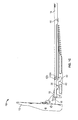
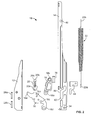
- FIG. 1 shows an example embodiment of the hinge assembly 10 which may include a first housing 12, a second housing 14, a mounting member 16, a link member 18, a locking member 20, and a biasing element 22.
- the first housing 12 is a part that is secured inside the body of the appliance 100 and receives the portion of the hinge assembly 10 that is located on the door 110.
- the first housing 12 is mounted in an upright position adjacent an opening of the compartment.
- the first housing 12 includes a front wall 12a and two side walls 12b that extend from the front wall 12a into the appliance 100. These walls 12a, 12b combine to form a channel 24 that extends along the longitudinal length of the first housing 12.
- the front wall 12a also includes an elongate first opening 26 and apertures that accept fastening means such as screws, nuts-and-bolts, or the like to secure the first housing 12 to the appliance 100.
- the first opening 26 includes a top portion 26a that has an upper edge 26c and is rectangular and a bottom portion 26b that tapers toward a lower edge 26d of the first opening 26.
- the side walls 12b have a substantially trapezoidal shape although other shapes may also be contemplated.
- the first housing 12 also includes an upper stop 28a and a lower stop 28b that extend transversely between the side walls 12b.
- the stops 28a, 28b may be formed through any means known in the art and in this embodiment are formed from pins or rivets which are inserted through apertures on one side wall and are secured to the first housing 12 through deformation on the other side wall.
- the upper stop 28a is located higher in the channel 24 than the lower stop 28b.
- the lower stop 28b is located closer to the front wall 12a than the upper stop 28a.
- the stops 28a, 28b have a round cross-section in this embodiment but other cross-sectional shapes are also contemplated.
- the cross-sectional area of the upper stop 28a may differ from that of the lower stop 28b in size and shape.
- the second housing 14 is a part that is secured inside the door 110 of the appliance 100 and may house a majority of the parts in this assembly.
- the second housing 14 is mounted in an upright position matching the orientation of the first housing 12.
- the second housing 14 at least partially houses the biasing element 22, the link member 18 and the mounting member 16.
- the second housing 14 may include a front wall 14a and two side walls 14b extending therefrom into the door 110 and may thereby form a channel 30 that extends along the length of the second housing 14 similar to the channel 24 of the first housing 12.
- the walls 14b may be configured with apertures to accommodate fastening means such as screws, nuts-and-bolts, or the like to secure the second housing 14 to the door 110.
- the walls 14a, 14b may also be configured with elongate beads or raised portions 32 for purposes of reinforcement.
- the side walls 14b may include transversely extending bars, shafts or pins by which some parts of the hinge assembly 10 are secured or pivotally coupled to the second housing 14 in order to structurally reinforce the second housing 14 and guard against deformation from repeated loading.
- the mounting member 16 may be a claw-like plate structure including a distal end 16a, a distal intermediate point 16b, a proximal intermediate point 16c, and a proximal end 16d.
- the proximal end 16d is pivotally coupled to a pin 34 ( FIG. 1A ) extending between the side walls 14b of the second housing 14.
- the mounting member 16 extends from the channel 30 of the second housing 14 through a second opening 36 ( FIG. 3 ) of the second housing 14 formed at the bottom of the front wall 14a.
- the mounting member 16 is also pivotally coupled to a first end 18a ( FIG. 2 ) of the link member 18 at the proximal intermediate point 16c.
- the link member 18, which may include a front wall and two side walls extending therefrom, also includes a second end 18b ( FIG. 2 ) which is connected to a moving end 22a ( FIG. 2 ) of the biasing element 22.
- a shaft 38 passes through the second end 18b of the link member 18 and the ends of the shaft 38 extend into passages 40 formed on the side wall 14b of the second housing 14.
- the passages 40 can be open slots, as shown in the drawings or can take the form of enclosed channels formed by molding the second housing 14 to integrate the passages 40 or by welding a separate cover piece over a pre-existing slot in the second housing 14.
- the shaft 38 may be formed from a pin, a rivet or the like and in the case of an open slot, as shown, may be dimensioned such that the ends of the shaft 38 project out of the passages 40.
- the shaft 38 may include features allowing the shaft 38 to be secured to the second housing 14 by fastening means known in the art such as seal rings adapted to be inserted in an annular groove on the shaft 38.
- the passages 40 define a predetermined path 42 that the ends of the shaft 38 travel along as the door 110 moves from a closed door position to an open door position.
- the predetermined path 42 may have a variety of forms and may be linear, curved, or a combination of the two. In the present embodiment, as shown in FIG. 1C , the predetermined path 42 can be substantially divided into an upper linear section 42a, a detent section 42b, and a lower linear section 42c.
- the detent position provides an intermediate and partially open position of the door which is commonly known as the "broil position."
- the shaft 38 is at the uppermost position in the predetermined path 42 when the door 110 is closed and is at the lowermost position when the door 110 is open.
- the delineation of the predetermined path 42 can also be supplemented by a cam bracket 44, shown in FIG. 5 , which is inserted in the second housing 14 abutting the passages 40 within the channel 30.
- the geometry of a bottom part 44a of the cam bracket 44 matches an upper contour 40a ( FIG. 3 ) of passages 40 such that the movement of the ends of the shaft 38 is further restricted by the cam bracket 44.
- the cam bracket 44 can be secured to the second housing 14 through a snap-in mechanism 44b and be further welded to the second housing 14.
- the biasing element 22 is a compression spring with a fixed end 22b and a moving end 22a both of which provide a hook for attachment.
- the fixed end 22b is connected to a pin 46 ( FIG. 1 C) extending between the side walls 14b in an upper portion of the channel 30 while the moving end 22a biases the link member 18 upward such that the mounting member 16 is biased to rotate toward the second housing 14.
- the locking member 20 may include a front wall and side walls extending therefrom and includes a bottom end 20a that is pivotally coupled to the distal intermediate point 16b of the mounting member 16.
- the locking member 20 can be manually pivoted and is dimensioned such that an upper end 20b of the locking member 20, which has a recess 20c, can rest against an upper edge 36a ( FIG. 3 ) of second opening 36 in a ready-for-mounting position or against the upper edge 26c of the first opening 26 in a mounted position.
- the locking member 20 maintains the mounting member 16 and the second housing 14 separated such that the distal end 16a of the mounting member 16 can be inserted into the first opening 26.
- the distal end 16a of the mounting member 16 includes a first abutting portion 17a, a second abutting portion 17b, and a slot 17c.
- the first abutting portion 17a may be formed from a pointed protrusion a tip of which is upwardly bent to form a recessed area at the top part of the protrusion that can receive the upper stop 28a.
- a bottom part of the protrusion includes a second abutting portion 17b that may be a concave recess that can receive the lower stop 28b.
- the bottom part of the protrusion also includes a slot 17c in which the lower edge 26d of the first opening 26 can fit into.
- the slot 17c may be straight or L-shaped as in this embodiment.
- the mounting member 16 is inserted into the first opening 26 so that the lower edge 26d of the first opening 26 enters the slot 17c and the recessed area of the first abutting portion 17a wraps around the upper stop 28a.
- the recess of the second abutting portion 17b is configured to be supported by the lower stop 28b in the process.
- the weight of the door 110 maintains the lower edge 26d of the first opening 26 in the slot 17c, and the upper stop 28a and the lower stop 28b prevent the mounting member 16 from rotating backward and being dislodged from the first housing 12.
Landscapes
- Engineering & Computer Science (AREA)
- Mechanical Engineering (AREA)
- Hinges (AREA)
Abstract
Description
- The present invention relates generally to hinge assemblies, and more particularly, to hinge assemblies for appliance doors.
- Hinge assemblies for doors in appliances such as ovens have various structures the differences of which can result in a number of advantages and drawbacks in terms of operability, reliability, durability, feel, etc. For example, a door may provide an intermediate position between a fully closed position and a fully opened position that may be helpful when using the appliance. However, such a door may also encounter problems when transitioning between multiple positions in that the movement may not be smooth and may require more force than desired. Also, a hinge assembly structure provided to overcome the former problem may not maintain the intermediate position as intended. Thus, there is a need to provide a hinge assembly structure that is an improvement over the existing structures while providing a solution to known problems.
- In accordance with a first aspect of the present invention, a hinge assembly for a door enclosing a compartment includes: a first housing configured to be mounted in a compartment, the first housing including a first opening; a second housing configured to be mounted in a door, the second opening including a front wall and two adjacent side walls extending therefrom defining a channel, the second housing further including a second opening on the front wall; a mounting member including a distal end, a proximal end, and a proximal intermediate point, the distal end configured to be inserted into the first opening and engage the first housing, and the mounting member pivotally coupled to the second housing at the proximal end and projecting out of the channel through the second opening; and a link member including a first end and a second end, the first end pivotally coupled to the proximal intermediate point, a shaft through the second end configured to slide along a predetermined path between the side walls, wherein the predetermined path is delineated by a pair of grooves formed on each of the side walls.
- According to a further aspect of the present invention a hinge assembly for a door enclosing a compartment includes: a first housing configured to be mounted in the compartment and including a front wall and two adjacent side walls extending therefrom defining a channel, the front wall including an opening leading to the channel, the opening partially defined by a lower edge, an upper stop and a lower stop extending between the side walls in the channel, the upper stop located higher in the channel than the lower stop, the lower stop located closer to the front wall than the upper stop; a second housing configured to be mounted in the door; and a mounting member including a distal end and a proximal end, the proximal end of the mounting member pivotally coupled to the second housing, the distal end of the mounting member including a first abutting portion, a second abutting portion and a slot, the distal end of the mounting member configured to be inserted in the opening so that the first abutting portion engages the upper stop, the second abutting portion engages the lower stop and the slot engages the lower edge.
-
-
FIG. 1 A is a side view of an example of a hinge assembly in a closed position in accordance with the present invention. -
FIG. 1 B is a side view of the hinge assembly in a partially opened position. -
FIG. 1 C is a side view of the hinge assembly in a fully opened position. -
FIG. 2 is an exploded view of the hinge assembly. -
FIG. 3 is a perspective view of a second housing. -
FIG. 4 is a perspective view of a first housing. -
FIG. 5 is a perspective view of a cam bracket. -
FIG. 6 is a side view of a mounting member. -
FIG. 7 is a view of an appliance in which the hinge assembly can be mounted. - Example embodiments that incorporate one or more aspects of the present invention are described and illustrated in the drawings. These illustrated examples are not intended to be a limitation on the present invention. For example, one or more aspects of the present invention can be utilized in other embodiments and even other types of devices.
-
FIG. 7 shows an example of anappliance 100 in which a hinge assembly of the present invention can be implemented. The type ofappliance 100 shown is an oven but the present invention may be applicable to any device with a compartment that is enclosed by adoor 110 such as a dishwasher, a furnace, a rotisserie, a kiln, or the like. In such appliances, thedoor 110 is generally mounted adjacent the compartment using a pair of hinge assemblies on each side of the bottom of thedoor 110 so that thedoor 110 is rotated upward for closing and rotated downward for opening. -
FIG. 1 shows an example embodiment of thehinge assembly 10 which may include afirst housing 12, asecond housing 14, amounting member 16, alink member 18, alocking member 20, and abiasing element 22. - The
first housing 12 is a part that is secured inside the body of theappliance 100 and receives the portion of thehinge assembly 10 that is located on thedoor 110. Thefirst housing 12 is mounted in an upright position adjacent an opening of the compartment. As shown inFIG. 4 , thefirst housing 12 includes afront wall 12a and twoside walls 12b that extend from thefront wall 12a into theappliance 100. Thesewalls channel 24 that extends along the longitudinal length of thefirst housing 12. Thefront wall 12a also includes an elongatefirst opening 26 and apertures that accept fastening means such as screws, nuts-and-bolts, or the like to secure thefirst housing 12 to theappliance 100. Thefirst opening 26 includes atop portion 26a that has anupper edge 26c and is rectangular and abottom portion 26b that tapers toward alower edge 26d of thefirst opening 26. In this embodiment, theside walls 12b have a substantially trapezoidal shape although other shapes may also be contemplated. Thefirst housing 12 also includes anupper stop 28a and alower stop 28b that extend transversely between theside walls 12b. Thestops first housing 12 through deformation on the other side wall. Theupper stop 28a is located higher in thechannel 24 than thelower stop 28b. Thelower stop 28b is located closer to thefront wall 12a than theupper stop 28a. Thestops upper stop 28a may differ from that of thelower stop 28b in size and shape. - The
second housing 14 is a part that is secured inside thedoor 110 of theappliance 100 and may house a majority of the parts in this assembly. Thesecond housing 14 is mounted in an upright position matching the orientation of thefirst housing 12. In this embodiment, thesecond housing 14 at least partially houses thebiasing element 22, thelink member 18 and themounting member 16. As shown inFIG. 3 , thesecond housing 14 may include afront wall 14a and twoside walls 14b extending therefrom into thedoor 110 and may thereby form achannel 30 that extends along the length of thesecond housing 14 similar to thechannel 24 of thefirst housing 12. Thewalls 14b may be configured with apertures to accommodate fastening means such as screws, nuts-and-bolts, or the like to secure thesecond housing 14 to thedoor 110. Thewalls portions 32 for purposes of reinforcement. Theside walls 14b may include transversely extending bars, shafts or pins by which some parts of thehinge assembly 10 are secured or pivotally coupled to thesecond housing 14 in order to structurally reinforce thesecond housing 14 and guard against deformation from repeated loading. - As shown in
FIG. 6 , themounting member 16 may be a claw-like plate structure including adistal end 16a, a distalintermediate point 16b, a proximalintermediate point 16c, and aproximal end 16d. Theproximal end 16d is pivotally coupled to a pin 34 (FIG. 1A ) extending between theside walls 14b of thesecond housing 14. Themounting member 16 extends from thechannel 30 of thesecond housing 14 through a second opening 36 (FIG. 3 ) of thesecond housing 14 formed at the bottom of thefront wall 14a. Themounting member 16 is also pivotally coupled to afirst end 18a (FIG. 2 ) of thelink member 18 at the proximalintermediate point 16c. Thelink member 18, which may include a front wall and two side walls extending therefrom, also includes asecond end 18b (FIG. 2 ) which is connected to a movingend 22a (FIG. 2 ) of thebiasing element 22. As shown inFIGS. 1A-1 C , ashaft 38 passes through thesecond end 18b of thelink member 18 and the ends of theshaft 38 extend intopassages 40 formed on theside wall 14b of thesecond housing 14. Thepassages 40 can be open slots, as shown in the drawings or can take the form of enclosed channels formed by molding thesecond housing 14 to integrate thepassages 40 or by welding a separate cover piece over a pre-existing slot in thesecond housing 14. Theshaft 38 may be formed from a pin, a rivet or the like and in the case of an open slot, as shown, may be dimensioned such that the ends of theshaft 38 project out of thepassages 40. Theshaft 38 may include features allowing theshaft 38 to be secured to thesecond housing 14 by fastening means known in the art such as seal rings adapted to be inserted in an annular groove on theshaft 38. - The
passages 40 define apredetermined path 42 that the ends of theshaft 38 travel along as thedoor 110 moves from a closed door position to an open door position. Thepredetermined path 42 may have a variety of forms and may be linear, curved, or a combination of the two. In the present embodiment, as shown inFIG. 1C , thepredetermined path 42 can be substantially divided into an upperlinear section 42a, adetent section 42b, and a lowerlinear section 42c. The detent position provides an intermediate and partially open position of the door which is commonly known as the "broil position." In this embodiment, theshaft 38 is at the uppermost position in thepredetermined path 42 when thedoor 110 is closed and is at the lowermost position when thedoor 110 is open. [0021] The delineation of thepredetermined path 42 can also be supplemented by acam bracket 44, shown inFIG. 5 , which is inserted in thesecond housing 14 abutting thepassages 40 within thechannel 30. The geometry of a bottom part 44a of thecam bracket 44 matches anupper contour 40a (FIG. 3 ) ofpassages 40 such that the movement of the ends of theshaft 38 is further restricted by thecam bracket 44. Thecam bracket 44 can be secured to thesecond housing 14 through a snap-inmechanism 44b and be further welded to thesecond housing 14. - In this embodiment, as shown in
FIG. 2 , the biasingelement 22 is a compression spring with afixed end 22b and a movingend 22a both of which provide a hook for attachment. Thefixed end 22b is connected to a pin 46 (FIG. 1 C) extending between theside walls 14b in an upper portion of thechannel 30 while the movingend 22a biases thelink member 18 upward such that the mountingmember 16 is biased to rotate toward thesecond housing 14. - As shown in
FIG. 2 , the lockingmember 20 may include a front wall and side walls extending therefrom and includes abottom end 20a that is pivotally coupled to the distalintermediate point 16b of the mountingmember 16. The lockingmember 20 can be manually pivoted and is dimensioned such that anupper end 20b of the lockingmember 20, which has arecess 20c, can rest against anupper edge 36a (FIG. 3 ) ofsecond opening 36 in a ready-for-mounting position or against theupper edge 26c of thefirst opening 26 in a mounted position. In the ready-for-mounting position, the lockingmember 20 maintains the mountingmember 16 and thesecond housing 14 separated such that thedistal end 16a of the mountingmember 16 can be inserted into thefirst opening 26. Once the mountingmember 16 is mounted to thefirst housing 26, the lockingmember 20 in the mounted position no longer intervenes with the pivoting of the hinge. - As shown in
FIG. 6 , thedistal end 16a of the mountingmember 16 includes a firstabutting portion 17a, a secondabutting portion 17b, and a slot 17c. The firstabutting portion 17a may be formed from a pointed protrusion a tip of which is upwardly bent to form a recessed area at the top part of the protrusion that can receive theupper stop 28a. A bottom part of the protrusion includes a secondabutting portion 17b that may be a concave recess that can receive thelower stop 28b. The bottom part of the protrusion also includes a slot 17c in which thelower edge 26d of thefirst opening 26 can fit into. The slot 17c may be straight or L-shaped as in this embodiment. - In order to mount the
door 110 on theappliance 100, as shown inFIG. 1A , the mountingmember 16 is inserted into thefirst opening 26 so that thelower edge 26d of thefirst opening 26 enters the slot 17c and the recessed area of the first abuttingportion 17a wraps around theupper stop 28a. The recess of the second abuttingportion 17b is configured to be supported by thelower stop 28b in the process. The weight of thedoor 110 maintains thelower edge 26d of thefirst opening 26 in the slot 17c, and theupper stop 28a and thelower stop 28b prevent the mountingmember 16 from rotating backward and being dislodged from thefirst housing 12. Once theupper end 20b of the lockingmember 20 is pivoted to rest on theupper edge 26c of thefirst opening 26, the mounting process is complete and thedoor 110 can be manually adjusted to move back and forth from the closed position going through the partially open position to the fully open position. - The invention has been described with reference to the example embodiments described above. Modifications and alterations will occur to others upon a reading and understanding of this specification. Example embodiments incorporating one or more aspects of the invention are intended to include all such modifications and alterations.
Claims (10)
- A hinge assembly (10) for a door (110) enclosing a compartment, the hinge assembly (110) including:a first housing (12) configured to be mounted in a compartment, the first housing including a first opening (26);a second housing (14) configured to be mounted in the door (110), the second housing (14) including a front wall (14a) and two adjacent side walls (14b) extending therefrom defining a channel (30), the second housing (14) further including a second opening (36) on the front wall (14a);a mounting member (16) including a distal end (16a), a proximal end (16d), and a proximal intermediate point (16c), the distal end (16a) configured to be inserted into the first opening (26) and engage the first housing (12), and the mounting member (16) pivotally coupled to the second housing (14) at the proximal end (16d) and projecting out of the channel (30) through the second opening (36); anda link member (18) including a first end (18a) and a second end (18b), the first end (18a) pivotally coupled to the proximal intermediate point (16c), a shaft (38) through the second end (18b) configured to slide along a predetermined path (42) between the side walls (14b),wherein the predetermined path (42) is delineated by a pair of passages (40) formed on each of the side walls (14b).
- The hinge assembly of claim 1, wherein the predetermined path (42) is further delineated by a cam bracket (44) inserted in the channel (30).
- The hinge assembly of claim 1, further including a biasing element (22) including a moving end (22a) and a fixed end (22b), the moving end pivotally coupled to the second end (18b) of the link member (18), the fixed end (22b) coupled to the second housing (14), the biasing element (22) biased to rotate the door (110) and abut the enclosed structure.
- The hinge assembly of claim 1, the mounting member (16) further including a distal intermediate point (16b), a locking member (20) pivotally coupled to the distal intermediate point (16b) of the mounting member (16), the locking member (20) having a coupled bottom end (20a) and a free upper end (20b), the locking member (20) configured to lock the second housing(14) about the mounting member (16) in a detent position.
- The hinge assembly of claim 1, wherein at least one of the front wall (14a) and the two side walls (14b) of the second housing member (14) is reinforced by an elongate bead.
- The hinge assembly (10) for a door (110) enclosing a compartment according to claim 1, the hinge assembly (10) including:said first housing (12) configured to be mounted in the compartment and including a front wall (12a) and two adjacent side walls (12b) extending therefrom defining a channel (24), the front wall (12a) including a first opening (26) leading to the channel (24), the first opening (26) partially defined by a lower edge (26d), an upper stop (28a) and a lower stop (28b) extending between the side walls (12b) in the channel (24), the upper stop (28a) located higher in the channel (24) than the lower stop (28b), the lower stop (28b) located closer to the front wall (12) than the upper stop (28a);said second housing (14) configured to be mounted in the door (110); andsaid mounting member (16) including thea distal end (16a) and the proximal end (16d), the proximal end (16d) of the mounting member (16) pivotally coupled to the second housing (14), the distal end (16a) of the mounting member (16) including a first abutting portion (17a), a second abutting portion (17b) and a slot (17c), the distal end (16a) of the mounting member (16) configured to be inserted in said first opening (26) so that the first abutting portion (17a) engages the upper stop (28a),the second abutting portion engages the lower stop (28b) and the slot (17c) engages the lower edge (26d).
- The hinge assembly of claim 6, wherein the distal end (16a) is a protrusion, the first abutting portion (17a) is formed at a top part of the protrusion, and the second abutting portion (17b) and the slot (17c) are formed at a bottom part of the protrusion.
- The hinge assembly of claim 7, wherein the first abutting portion (17a) is formed by an upwardly bent tip and the second abutting portion (17b) is formed by a recess in the protrusion.
- The hinge assembly of claim 6, wherein the first opening (26) is substantially elongate and includes a top portion (26a) that is rectangular and a bottom portion (26b) that the gradually tapers toward the lower edge (26d).
- The hinge assembly of claim 6, wherein the upper and lower stops (28a, 28b) have a round cross section.
Applications Claiming Priority (2)
| Application Number | Priority Date | Filing Date | Title |
|---|---|---|---|
| US12/416,243 US20100251521A1 (en) | 2009-04-01 | 2009-04-01 | Door hinge assembly |
| EP10723840A EP2414608A2 (en) | 2009-04-01 | 2010-03-29 | Door hinge assembly |
Related Parent Applications (1)
| Application Number | Title | Priority Date | Filing Date |
|---|---|---|---|
| EP10723840A Division EP2414608A2 (en) | 2009-04-01 | 2010-03-29 | Door hinge assembly |
Publications (1)
| Publication Number | Publication Date |
|---|---|
| EP2759668A1 true EP2759668A1 (en) | 2014-07-30 |
Family
ID=42289461
Family Applications (2)
| Application Number | Title | Priority Date | Filing Date |
|---|---|---|---|
| EP10723840A Withdrawn EP2414608A2 (en) | 2009-04-01 | 2010-03-29 | Door hinge assembly |
| EP14165930.0A Withdrawn EP2759668A1 (en) | 2009-04-01 | 2010-03-29 | Door hinge assembly |
Family Applications Before (1)
| Application Number | Title | Priority Date | Filing Date |
|---|---|---|---|
| EP10723840A Withdrawn EP2414608A2 (en) | 2009-04-01 | 2010-03-29 | Door hinge assembly |
Country Status (6)
| Country | Link |
|---|---|
| US (1) | US20100251521A1 (en) |
| EP (2) | EP2414608A2 (en) |
| CN (1) | CN102405325B (en) |
| AU (1) | AU2010236885B2 (en) |
| CA (1) | CA2756227C (en) |
| WO (1) | WO2010120481A2 (en) |
Families Citing this family (15)
| Publication number | Priority date | Publication date | Assignee | Title |
|---|---|---|---|---|
| WO2012115467A2 (en) * | 2011-02-24 | 2012-08-30 | Lg Electronics Inc. | Laundry treatment apparatus |
| SI24023A (en) * | 2012-03-06 | 2013-09-30 | Turna D.O.O. | A device and a method for controlled door closing |
| US9404299B2 (en) * | 2012-05-02 | 2016-08-02 | Bsh Home Appliances Corporation | Home appliance with adjustable hinges |
| ITBO20120244A1 (en) * | 2012-05-04 | 2013-11-05 | Nuova Star Spa | HINGE FOR DOORS OR DOORS, OF HOUSEHOLD APPLIANCES SUCH AS OVENS, DISHWASHER OR SIMILAR |
| CN105209705B (en) * | 2013-04-18 | 2017-02-15 | 深圳市金合联投资有限公司 | Hinge |
| CN105593449A (en) * | 2013-09-02 | 2016-05-18 | 深圳市金合联投资有限公司 | Hinge |
| US9181737B1 (en) | 2014-06-03 | 2015-11-10 | Whirlpool Corporation | Oven door opening magnetic hinge |
| DE102015110561A1 (en) * | 2015-07-01 | 2017-01-05 | Form Orange Produktentwicklung | Drawer with a bottom plate, a cover, a rear wall and two side walls, which are firmly connected |
| ITUB20155424A1 (en) * | 2015-11-10 | 2017-05-10 | C M I Cerniere Mecc Industriali Srl | HINGE DEVICE WITH POSSIBILITY OF BREATHER OPENING |
| ITUB20156022A1 (en) * | 2015-11-30 | 2017-05-30 | Leandro Cappellotto | MOVEMENT MECHANISM OF FURNITURE DOORS |
| US11071439B2 (en) * | 2015-12-21 | 2021-07-27 | Electrolux Appliances Aktiebolag | Bracket, dishwasher and method of attaching a structure to a wall of a dishwasher |
| US11377890B1 (en) * | 2020-12-31 | 2022-07-05 | Whirlpool Corporation | Appliance door hinge assembly |
| WO2022217423A1 (en) * | 2021-04-12 | 2022-10-20 | 深圳市金合联供应链技术有限公司 | Flap-down door cushion hinge |
| IT202200012248A1 (en) * | 2022-06-09 | 2023-12-09 | C M I Cerniere Mecc Industriali Srl | SIMPLIFIED MULTI-FUNCTIONALITY HINGE |
| WO2024111898A1 (en) * | 2022-11-24 | 2024-05-30 | 삼성전자주식회사 | Cooking appliance |
Citations (4)
| Publication number | Priority date | Publication date | Assignee | Title |
|---|---|---|---|---|
| DE10152907A1 (en) * | 2001-02-15 | 2002-09-05 | Gronbach Forschungs Und Entwic | Hinge for a stove hatch |
| US20060032019A1 (en) * | 2004-05-03 | 2006-02-16 | Adam Kistner | Appliance hinge |
| US20070101542A1 (en) * | 2005-11-04 | 2007-05-10 | Poong Won Industry Co., Ltd. | Door hinge |
| US20070232135A1 (en) * | 2006-03-31 | 2007-10-04 | Nuova Star S.P.A. | Connection for hinge |
Family Cites Families (15)
| Publication number | Priority date | Publication date | Assignee | Title |
|---|---|---|---|---|
| IT1257777B (en) * | 1992-03-26 | 1996-02-13 | IMPROVED HINGE FOR THE RELEASE OF DOORS OR DOORS TO A RESPECTIVE SUPPORT STRUCTURE | |
| DE10019738C1 (en) * | 2000-04-20 | 2001-08-30 | Edscha Ag | Drivable flap hinge |
| US6453510B1 (en) * | 2000-09-21 | 2002-09-24 | Mansfield Assemblies Co. | Single link dual-contact point hinge assembly |
| US20030172920A1 (en) * | 2001-02-15 | 2003-09-18 | Lina Gronbach | Hinge for a stove door |
| US6968597B2 (en) * | 2002-05-31 | 2005-11-29 | Mansfield Assemblies Co. | Hinge assembly having improved stop |
| KR100474425B1 (en) * | 2003-04-30 | 2005-03-10 | 삼성전자주식회사 | Hinge apparatus for cover of office machine |
| US6892424B1 (en) * | 2003-08-08 | 2005-05-17 | Mansfield Assemblies Co. | Single link hinge assembly with break-away link |
| US7134169B2 (en) * | 2004-01-15 | 2006-11-14 | Mansfield Assemblies Co. | Hinge assembly and door mounting system including same |
| BRPI0513268B1 (en) * | 2004-07-14 | 2016-05-17 | Blum Gmbh Julius | actuation mechanism for a supported actuator arm that can rotate |
| US7945996B2 (en) * | 2007-04-05 | 2011-05-24 | Boise State University | Self-closing hinge |
| CN101338783B (en) * | 2007-07-04 | 2011-03-30 | 深圳富泰宏精密工业有限公司 | Hinge structure and portable electronic device using the hinge structure |
| US20090025181A1 (en) * | 2007-07-26 | 2009-01-29 | George Burger | Slow Closing Hinge Apparatus |
| US20090126154A1 (en) * | 2007-11-21 | 2009-05-21 | Cheng Uei Precision Industry Co., Ltd. | Hinge apparatus |
| KR100959211B1 (en) * | 2008-04-22 | 2010-05-19 | 풍원공업 주식회사 | Door lock |
| US8201304B2 (en) * | 2009-02-25 | 2012-06-19 | General Electric Company | Compliant door hinge |
-
2009
- 2009-04-01 US US12/416,243 patent/US20100251521A1/en not_active Abandoned
-
2010
- 2010-03-29 EP EP10723840A patent/EP2414608A2/en not_active Withdrawn
- 2010-03-29 EP EP14165930.0A patent/EP2759668A1/en not_active Withdrawn
- 2010-03-29 CN CN201080014822.5A patent/CN102405325B/en not_active Expired - Fee Related
- 2010-03-29 AU AU2010236885A patent/AU2010236885B2/en not_active Ceased
- 2010-03-29 CA CA2756227A patent/CA2756227C/en not_active Expired - Fee Related
- 2010-03-29 WO PCT/US2010/029011 patent/WO2010120481A2/en not_active Ceased
Patent Citations (4)
| Publication number | Priority date | Publication date | Assignee | Title |
|---|---|---|---|---|
| DE10152907A1 (en) * | 2001-02-15 | 2002-09-05 | Gronbach Forschungs Und Entwic | Hinge for a stove hatch |
| US20060032019A1 (en) * | 2004-05-03 | 2006-02-16 | Adam Kistner | Appliance hinge |
| US20070101542A1 (en) * | 2005-11-04 | 2007-05-10 | Poong Won Industry Co., Ltd. | Door hinge |
| US20070232135A1 (en) * | 2006-03-31 | 2007-10-04 | Nuova Star S.P.A. | Connection for hinge |
Also Published As
| Publication number | Publication date |
|---|---|
| CN102405325A (en) | 2012-04-04 |
| CA2756227C (en) | 2015-01-27 |
| US20100251521A1 (en) | 2010-10-07 |
| CA2756227A1 (en) | 2010-10-21 |
| EP2414608A2 (en) | 2012-02-08 |
| WO2010120481A2 (en) | 2010-10-21 |
| AU2010236885A1 (en) | 2011-10-13 |
| WO2010120481A3 (en) | 2010-12-09 |
| CN102405325B (en) | 2014-10-29 |
| AU2010236885B2 (en) | 2014-08-14 |
Similar Documents
| Publication | Publication Date | Title |
|---|---|---|
| CA2756227C (en) | Door hinge assembly | |
| EP2035640B1 (en) | Domestic appliance with concealed hinge | |
| EP2295692B1 (en) | Door or wing for electrical household appliances | |
| US8250707B2 (en) | Door hinge assembly with intermediate stop position | |
| US11841144B2 (en) | Cooking appliance | |
| US9307582B2 (en) | Microwave oven having hood | |
| EP2749722A1 (en) | Hinge assembly with damping device | |
| EP2687786A2 (en) | Assembly of a door hinge of an oven of a household appliance with dampened closing | |
| WO2015023646A1 (en) | Range limited latch | |
| US6601897B2 (en) | Vehicle interior panel having compartment and swing door | |
| EP4023944B1 (en) | Appliance door hinge assembly | |
| US11199331B2 (en) | Cooking oven with cavity drawer having movable door | |
| US7765643B2 (en) | Connection for hinge | |
| EP4007870B1 (en) | Vertical hood | |
| US10704307B1 (en) | Adjustable receiver for appliance hinge | |
| EP3747703B1 (en) | Slide door structure | |
| AU2010244727B2 (en) | Door hinge for opening and closing a door of a domestic appliance | |
| CN118900972A (en) | Door and household appliance having a movable handle with a handle bracket engaged above a front panel | |
| EP2532973B1 (en) | Household Appliance | |
| KR101549511B1 (en) | Door handle | |
| KR102588817B1 (en) | Wing knob device for air vent | |
| WO2011113212A1 (en) | Locking device for windows and doors | |
| EP4180598B1 (en) | Hinge and electrical device | |
| EP1998117B1 (en) | Food cooking oven with a door closing device | |
| EP2110628A1 (en) | Home refrigerator |
Legal Events
| Date | Code | Title | Description |
|---|---|---|---|
| 17P | Request for examination filed |
Effective date: 20140425 |
|
| AC | Divisional application: reference to earlier application |
Ref document number: 2414608 Country of ref document: EP Kind code of ref document: P |
|
| AK | Designated contracting states |
Kind code of ref document: A1 Designated state(s): AT BE BG CH CY CZ DE DK EE ES FI FR GB GR HR HU IE IS IT LI LT LU LV MC MK MT NL NO PL PT RO SE SI SK SM TR |
|
| PUAI | Public reference made under article 153(3) epc to a published international application that has entered the european phase |
Free format text: ORIGINAL CODE: 0009012 |
|
| RAP1 | Party data changed (applicant data changed or rights of an application transferred) |
Owner name: ELECTROLUX HOME PRODUCTS, INC. |
|
| RBV | Designated contracting states (corrected) |
Designated state(s): AT BE BG CH CY CZ DE DK EE ES FI FR GB GR HR HU IE IS IT LI LT LU LV MC MK MT NL NO PL PT RO SE SI SK SM TR |
|
| R17P | Request for examination filed (corrected) |
Effective date: 20150113 |
|
| STAA | Information on the status of an ep patent application or granted ep patent |
Free format text: STATUS: THE APPLICATION IS DEEMED TO BE WITHDRAWN |
|
| 18D | Application deemed to be withdrawn |
Effective date: 20161001 |