EP2759623A1 - Spinning machine, take-up device, and textile machine - Google Patents
Spinning machine, take-up device, and textile machine Download PDFInfo
- Publication number
- EP2759623A1 EP2759623A1 EP12834445.4A EP12834445A EP2759623A1 EP 2759623 A1 EP2759623 A1 EP 2759623A1 EP 12834445 A EP12834445 A EP 12834445A EP 2759623 A1 EP2759623 A1 EP 2759623A1
- Authority
- EP
- European Patent Office
- Prior art keywords
- section
- motor
- abnormality
- yarn
- spinning
- Prior art date
- Legal status (The legal status is an assumption and is not a legal conclusion. Google has not performed a legal analysis and makes no representation as to the accuracy of the status listed.)
- Withdrawn
Links
- 238000009987 spinning Methods 0.000 title claims abstract description 128
- 239000004753 textile Substances 0.000 title claims abstract description 22
- 230000005856 abnormality Effects 0.000 claims abstract description 128
- 125000004122 cyclic group Chemical group 0.000 claims abstract description 107
- 230000000737 periodic effect Effects 0.000 claims abstract description 95
- 238000004804 winding Methods 0.000 claims abstract description 85
- 238000012544 monitoring process Methods 0.000 claims abstract description 78
- 239000000835 fiber Substances 0.000 claims abstract description 43
- 238000001514 detection method Methods 0.000 claims abstract description 32
- 230000007547 defect Effects 0.000 abstract description 12
- 238000000034 method Methods 0.000 description 23
- 230000008569 process Effects 0.000 description 13
- 238000011144 upstream manufacturing Methods 0.000 description 10
- 230000002093 peripheral effect Effects 0.000 description 6
- 230000009471 action Effects 0.000 description 3
- 238000010586 diagram Methods 0.000 description 3
- 230000001902 propagating effect Effects 0.000 description 3
- 230000007246 mechanism Effects 0.000 description 2
- 230000004397 blinking Effects 0.000 description 1
- 230000000694 effects Effects 0.000 description 1
- 230000006870 function Effects 0.000 description 1
- 239000004973 liquid crystal related substance Substances 0.000 description 1
- 230000000644 propagated effect Effects 0.000 description 1
- 238000007378 ring spinning Methods 0.000 description 1
- 230000032258 transport Effects 0.000 description 1
Images


Classifications
-
- D—TEXTILES; PAPER
- D01—NATURAL OR MAN-MADE THREADS OR FIBRES; SPINNING
- D01H—SPINNING OR TWISTING
- D01H5/00—Drafting machines or arrangements ; Threading of roving into drafting machine
- D01H5/18—Drafting machines or arrangements without fallers or like pinned bars
- D01H5/32—Regulating or varying draft
- D01H5/38—Regulating or varying draft in response to irregularities in material ; Measuring irregularities
-
- B—PERFORMING OPERATIONS; TRANSPORTING
- B65—CONVEYING; PACKING; STORING; HANDLING THIN OR FILAMENTARY MATERIAL
- B65H—HANDLING THIN OR FILAMENTARY MATERIAL, e.g. SHEETS, WEBS, CABLES
- B65H54/00—Winding, coiling, or depositing filamentary material
- B65H54/02—Winding and traversing material on to reels, bobbins, tubes, or like package cores or formers
- B65H54/40—Arrangements for rotating packages
- B65H54/42—Arrangements for rotating packages in which the package, core, or former is rotated by frictional contact of its periphery with a driving surface
-
- B—PERFORMING OPERATIONS; TRANSPORTING
- B65—CONVEYING; PACKING; STORING; HANDLING THIN OR FILAMENTARY MATERIAL
- B65H—HANDLING THIN OR FILAMENTARY MATERIAL, e.g. SHEETS, WEBS, CABLES
- B65H63/00—Warning or safety devices, e.g. automatic fault detectors, stop-motions ; Quality control of the package
- B65H63/04—Warning or safety devices, e.g. automatic fault detectors, stop-motions ; Quality control of the package responsive to excessive tension or irregular operation of apparatus
-
- D—TEXTILES; PAPER
- D01—NATURAL OR MAN-MADE THREADS OR FIBRES; SPINNING
- D01H—SPINNING OR TWISTING
- D01H13/00—Other common constructional features, details or accessories
- D01H13/14—Warning or safety devices, e.g. automatic fault detectors, stop motions ; Monitoring the entanglement of slivers in drafting arrangements
-
- D—TEXTILES; PAPER
- D01—NATURAL OR MAN-MADE THREADS OR FIBRES; SPINNING
- D01H—SPINNING OR TWISTING
- D01H13/00—Other common constructional features, details or accessories
- D01H13/32—Counting, measuring, recording or registering devices
-
- B—PERFORMING OPERATIONS; TRANSPORTING
- B65—CONVEYING; PACKING; STORING; HANDLING THIN OR FILAMENTARY MATERIAL
- B65H—HANDLING THIN OR FILAMENTARY MATERIAL, e.g. SHEETS, WEBS, CABLES
- B65H2701/00—Handled material; Storage means
- B65H2701/30—Handled filamentary material
- B65H2701/31—Textiles threads or artificial strands of filaments
Definitions
- the present invention relates to a spinning machine, a winding device, and a textile machine.
- Patent Literature 1 A textile machine described in Patent Literature 1 has been conventionally known as a technique in such a field.
- the technique described in Patent Literature 1 digitizes a yarn unevenness electric signal obtained from a yarn unevenness detector (for example, a clearer) installed on a textile machine such as a spinning frame, and analyzes the digitized signal with a calculator, thereby detecting yarn unevenness.
- a yarn unevenness detector for example, a clearer
- Patent Literature 2 a technique described in Patent Literature 2 has been known as an abnormality detection method for a drafting device in a spinning machine. With this technique, variation in load torque acting on a driving motor that drives a drafting roller is monitored, and the operation of the drafting device is stopped if it is determined that there is an abnormality because the variation of the load torque exceeded a certain rate.
- Patent Literature 1 may fail to detect relatively long-periodic unevenness if an unevenness detector has insufficient detection accuracy.
- the technique described in Patent Literature 2 monitors variation in load torque on a motor, but does not detect a cyclic abnormality.
- An object of the present invention is to provide a spinning machine that is capable of detecting a cyclic abnormality of a drafting roller and improving detection accuracy of such an abnormality.
- the present invention aims to provide a winding device that is capable of detecting a cyclic abnormality of a rotary drum and improving detection accuracy of such an abnormality.
- the present invention aims to provide a textile machine that is capable of detecting a cyclic abnormality of a rotary body and improving detection accuracy of such an abnormality.
- a spinning machine includes: a drafting roller drafting a fiber band; a motor rotationally driving the drafting roller; a monitoring section monitoring at least one of torque and revolution speed of the motor; and a periodic unevenness determining section determining a cyclic abnormality of the drafting roller that appears as periodic unevenness on the fiber band, on the basis of a monitor result of the monitoring section.
- This spinning machine monitors at least one of the torque and the revolution speed of the motor driving the drafting roller that drafts the fiber band, determining whether or not a cyclic abnormality appears on the drafting roller on the basis of the monitor result.
- the cyclic abnormality of the drafting roller that appears as periodic unevenness on the fiber band can be detected, and a cyclic abnormality of the drafted fiber band can be detected.
- a conventional unevenness detector commonly installed on a spinning machine may fail to detect long-periodic unevenness.
- the values of torque and/or revolution speed (monitor value) of the motor can be detected precisely.
- the periodic unevenness determining section can determine the periodic abnormality on the fiber band in higher accuracy than the clearer, on the basis of the monitor value obtained by monitoring the motor.
- the periodic unevenness determining section may perform frequency analysis on a value relating to at least one of the torque and the revolution that are each the monitor result of the monitoring section to determine the cyclic abnormality of the drafting roller.
- the frequency analysis is effective means for determining a cyclic abnormality, thus the cyclic abnormality of the drafting roller can be detected precisely.
- the spinning machine may include a plurality of such drafting rollers arranged along a transporting direction of the fiber band, and a plurality of such motors independently driving the drafting rollers.
- the periodic unevenness determining section may determine which motor out of the motors has cyclic abnormalities, on the basis of the monitor result of the monitoring section. With this configuration, the periodic unevenness determining section can reliably identify which drafting roller among the drafting rollers has a cause of a periodic unevenness. It is difficult to determine the drafting roller causing the periodic unevenness with unevenness detection using a conventional clearer in the case where multiple periodic unevenness occurs in an overlapping manner.
- the spinning machine may further include a periodic unevenness detecting section disposed on a downstream of the drafting roller.
- the periodic unevenness detecting section may detect unevenness on the fiber band drafted with the drafting roller.
- the periodic unevenness determining section may determine a cyclic abnormality of the drafting roller on the basis of the monitor result of the monitoring section and a detection result of the unevenness detecting section to detect the periodic unevenness on the fiber band.
- the periodic unevenness determining section can precisely detect the cyclic abnormality of the drafting rollers on the basis of the monitor result on the motors driving the drafting rollers and the detection result of the unevenness on the fiber band detected by the unevenness detecting section.
- the spinning machine may further include a notifying section notifying information relating to the monitor result of the monitoring section.
- a notifying section notifying information relating to the monitor result of the monitoring section.
- An operator can easily check for a cyclic abnormality of the drafting rollers and promptly take an appropriate action, on the basis of the information notified by the notifying section.
- the notifying section are a displaying section and an audio outputting section. In the case where the notifying section is the displaying section, the operator can easily check the cyclic abnormality by looking at the displaying section.
- the spinning machine may further include: an air spinning device spinning the fiber band drafted with the drafting roller, with swirl flows; and a winding device winding the fiber band spun from the air spinning device into a package.
- the periodic unevenness determining section may determine a cyclic abnormality of the drafting roller while the winding device winds the fiber band into the package.
- the periodic unevenness determining section can determine a cyclic abnormality of the drafting rollers even while the winding device winds the fiber band into the package. Thus, decrease in operating efficiency of the spinning machine can be reduced.
- a windier includes: a rotary drum making contacting with and rotating a winding package to cause the winding package to wind a yarn; a motor rotationally driving the rotary drum; a monitoring section monitoring at least one of torque and revolution speed of the motor; and a determining section determining a cyclic abnormality of the rotary drum on the basis of a monitor result of the monitoring section.
- This winding device monitors at least one of the torque and the revolution speed of the motor driving the rotary drum, determining whether or not a cyclic abnormality appears on the rotary drum on the basis of the monitor result.
- the cyclic abnormality of the rotary drum can be detected to ensure detection of an abnormality such as eccentricity of the winding package, therefore, the reliability of the winding device can be improved.
- the winding device are a winding device in a spinning machine, and an automatic winder.
- the determining section may perform frequency analysis on a value relating to at least one of the torque and the revolution speed that are each the monitor result of the monitoring section to determine the cyclic abnormality of the rotary drum.
- the frequency analysis is effective means for determining a cyclic abnormality, thus the cyclic abnormality of the rotary drum can be detected precisely.
- the winding device may further include: a notifying section notifying information relating to the monitor result of the monitoring section.
- a notifying section notifying information relating to the monitor result of the monitoring section.
- the operator can easily check a cyclic abnormality of the drafting rollers and promptly take an appropriate action, on the basis of the information notified by the notifying section.
- the notifying section are a displaying section and an audio outputting section. In the case where the notifying section is the displaying section, the operator can easily check the cyclic abnormality by looking at the displaying section.
- a textile machine includes: a rotary body transporting a fiber band; a motor rotationally driving the rotary body; a monitoring section monitoring at least one of torque and revolution speed of the motor; and a determining section determining a cyclic abnormality of the rotary body on the basis of a monitor result of the monitoring section.
- a rotary body transporting a fiber band includes a device transporting a fiber band and other devices capable of performing certain processing, such as “drafting a fiber band (sliver)" and/or “winding a yarn”, accompanying the rotation of the rotary body.
- the determining section may perform frequency analysis on a value relating to at least one of the torque and the revolution speed that are each the monitor result of the monitoring section to determine the cyclic abnormality of the rotary body.
- the frequency analysis is effective means for determining a cyclic abnormality, thus the cyclic abnormality of the rotary body can be detected precisely.
- the textile machine may further include: a notifying section notifying information relating to the monitor result of the monitoring section.
- the operator can easily check a cyclic abnormality of the rotary body and promptly take an appropriate action, on the basis of the information notified by the notifying section.
- Examples of the notifying section are a displaying section and an audio outputting section. In the case where the notifying section is the displaying section, the operator can easily check the cyclic abnormality by looking at the displaying section.
- a spinning machine of the present invention is capable of detecting a cyclic abnormality of a drafting roller and improving detection accuracy of such an abnormality.
- a winding device of the present invention is capable of detecting a cyclic abnormality of a rotary drum and improving detection accuracy of such an abnormality.
- a textile machine of the present invention is capable of detecting a cyclic abnormality of a rotary body and improving detection accuracy of such an abnormality.
- a spinning frame (spinning machine) according to an embodiment of the present invention is described with reference to the accompanying drawings. Note that an "upstream” and a “downstream” in this description mean the upstream and the downstream in a running direction of a yarn during spinning, respectively.
- a spinning frame 1 illustrated in Fig. 1 and Fig. 2 includes a plurality of spinning units 2 aligned next to each other.
- the spinning frame 1 includes a yarnm joining carriage 3 capable of running along the aligning direction of the spinning units 2, a motor box 5, a central controller (not illustrated) controlling the spinning frame 1, and unit controllers 60 (refer to Fig. 3 and Fig. 4 ) controlling the spinning units 2.
- the central controller may be installed in the motor box 5.
- the central controller is electrically connected to the multiple unit controllers 60 to integrally control the unit controllers 60.
- the unit controller 60 is provided to each spinning unit 2 to independently control the spinning unit 2 (will be described in detail later).
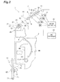
- Each spinning unit 2 (spinning machine) includes a drafting device 7, a spinning section 9 (air spinning device), a yarn clearer 52, a yarn slack-eliminating device 12 (yarn storage device), and a winding device 13, in this order from upstream to downstream.
- the drafting device 7 is provided near the top end of a case 6 of the spinning frame 1.
- a fiber band 8 fed from the drafting device 7 is supplied to the spinning section 9 to be spun.
- a spun yarn 10 that has been spun by the spinning section 9 passes through the yarn clearer 52. Thereafter, the spun yarn 10 is fed by the yarn slack-eliminating device 12 and wound by the winding device 13, whereby a package 45 is formed.
- the drafting device 7 drafts a sliver 15 to obtain a fiber band 8.
- the drafting device 7 includes a plurality of pairs of drafting rollers 16, 17, 19, and 20 (rotary bodies) aligned along a feeding direction (transporting direction) of the fiber band 8 and drafts the fiber band 8 with the drafting rollers 16, 17, 19, and 20.
- the drafting device 7 includes back rollers 16, third rollers 17, second rollers 19 around which apron belts 18 are wound, and front rollers 20, serving as the drafting rollers 16, 17, 19, and 20, respectively.
- the drafting rollers 16, 17, 19, and 20 each include a pair of a top roller and a bottom roller. The top roller and the bottom roller are arranged to sandwich therebetween the sliver 15.
- the drafting device 7 includes a drafting cradle (not illustrated).
- the drafting cradle supports the top rollers and opens and closes by swinging about a certain pivot. Under a state in which the drafting cradle is closed, the top rollers make contact with the bottom rollers, and the drafting device 7 drafts the fiber band 8. If the drafting cradle is not closed at a proper position, a periodic unevenness can be generated on the fiber band 8.
- the drafting device 7 includes motors 31 to 34 to drive the bottom rollers of the drafting rollers 16, 17, 19, and 20.
- the motor 31 rotationally drives the back roller 16.
- the motor 32 rotationally drives the third roller 17.
- the motor 33 rotationally drives the second roller 19.
- the motor 34 rotationally drives the front roller 20.
- a single motor rotationally drives a single drafting roller in the present embodiment, a single motor may rotationally drive a plurality of drafting rollers.
- a single motor may rotationally drive the back roller 16 and the third roller 17 which are drafting rollers in a low-speed side.
- the top rollers of the drafting rollers 16, 17, 19, and 20 are configured to rotate by following the bottom rollers rotationally driven by the motors 31 to 34.
- the spinning unit 2 includes a motor controller 30 that controls the rotation of the motors 31 to 34.
- the motor controller 30 is electrically connected to the motors 31 to 34.
- the motor controller 30 can detect load torque acting on each of the motors 31 to 34.
- the motor controller 30 can detect the revolution speed of the output shaft of each of the motors 31 to 34. It is enough for the motor controller 30 to be capable of detecting at least one of the torque and the revolution speed.
- the motor controller 30 outputs data relating to the torque and/or the revolution speed of each of the motor s 31 to 34 to the unit controller 60.
- the detailed structure of the spinning section 9 is not illustrated, but the present embodiment employs a pneumatic structure using swirling air flow (swirl flow) to twist the fiber band 8, so as to produce a spun yarn 10.
- swirling air flow swirling air flow
- the yarn slack-eliminating device 12 applies certain tension to the spun yarn 10 and draws the spun yarn 10 from the spinning section 9.
- the yarn slack-eliminating device 12 prevents the spun yarn 10 from slacking by storing the spun yarn 10 fed out from the spinning section 9 when the yarn joining carriage 3 performs yarn joining.
- the yarn slack-eliminating device 12 adjusts the tension of the spun yarn 10 so as to prevent the variation in the tension of the spun yarn 10 at the winding device 13 from propagating to the spinning section 9.
- the yarn slack-eliminating device 12 includes a slack eliminating roller (yarn storage roller) 21, a yarn hooking member 22, an upstream guide 23, an electric motor 25, a downstream guide 26, and a yarn storage amount sensor 27.
- the yarn hooking member 22 is configured to hook the spun yarn 10.
- the yarn hooking member 22 hooked with the spun yarn 10 integrally rotates with the slack eliminating roller 21, thereby winding the spun yarn 10 on an outer peripheral surface of the slack eliminating roller 21.
- the slack eliminating roller 21 winds a certain amount of the spun yarn 10 around the outer peripheral surface thereof to store the spun yarn 10.
- the slack eliminating roller 21 is rotationally driven by the electric motor 25. Rotation of the slack eliminating roller 21 tightens the spun yarn 10 wound around the outer peripheral surface of the slack eliminating roller 21, thereby drawing the spun yarn 10 from the upstream of the yarn slack-eliminating device 12. That is, when the spun yarn 10 is wound around the outer peripheral surface of the slack eliminating roller 21, rotation of the slack eliminating roller 21 in a certain revolution speed applies certain tension to the spun yarn 10 and draws the spun yarn 10 out from the spinning section 9 at a certain speed, thereby transporting the spun yarn 10 to the downstream at a certain speed.
- a certain contact area can be obtained between the slack eliminating roller 21 and the spun yarn 10 by winding the certain amount of the spun yarn 10 around the outer peripheral surface of the slack eliminating roller 21.
- This configuration enables the slack eliminating roller 21 to hold and draw the spun yarn 10 with sufficient strength.
- the spun yarn 10 can be drawn out from the spinning section 9 at a stable speed without causing slip for example.
- the spinning frame 1 of the present embodiment applies the tension to the spun yarn 10 with the slack-eliminating device 12, thereby drawing out the spun yarn 10 from the spinning section 9 at an accurate speed with less variation.
- the yarn storage amount sensor 27 detects a storage amount of the spun yarn 10 stored on the slack eliminating roller 21 in a non-contact manner and sends the detected storage amount to the unit controller 60.
- the upstream guide 23 is arranged slightly upstream of the slack eliminating roller 21.
- the upstream guide 23 properly guides the spun yarn 10 to the outer peripheral surface of the slack eliminating roller 21.
- the upstream guide 23 prevents a twist of the spun yarn 10 propagating from the spinning section 9 from being propagated to the downstream of the upstream guide 23.
- the yarn clearer 52 is provided between the spinning section 9 and the slack-eliminating device 12, in the front face side of the case 6 of the spinning frame 1.
- the spun yarn 10 spun in the spinning section 9 passes through the yarn clearer 52 before being wound by the slack-eliminating device 12.
- the yarn clearer 52 monitors the thickness of the spun yarn 10 running therethrough and sends a yarn defect detection signal to the unit controller 60 (controller) if a yarn defect on the spun yarn 10 is detected.
- the yarn clearer 52 is arranged downstream of the drafting device 7 and serves as an unevenness detecting section detecting unevenness on the fiber band 8 drafted with the drafting device 7.
- the unit controller 60 stops the drafting device 7, the spinning section 9, and other devices, in a certain timing. In this case, the unit controller 60 cuts the spun yarn 10 by interrupting the blow of compressed air from a nozzle in the spinning section 9 which generates swirl flow.
- the unit controller 60 sends a control signal to the yarn joining carriage 3 to move the yarn joining carriage 3 to the front of the relevant spinning unit 2. Thereafter, the unit controller 60 drives the spinning section 9 and other devices again, causes the yarn joining carriage 3 to perform yarn joining, and restarts winding.
- the yarn slack-eliminating device 12 eliminates slack on the spun yarn 10 by storing the spun yarn 10 continuously fed out from the spinning section 9 on the slack eliminating roller 21 during a period from the restart of spinning in the spinning section 9 to the restart of winding.
- the yarn joining carriage 3 includes a splicer (yarn joining device) 43, a suction pipe 44, and a suction mouth 46.
- a splicer yarn joining device
- the suction pipe 44 swings up and down about a pivot, sucks and catches a yarn end fed out from the spinning section 9, and guides it to the splicer 43.
- the suction mouth 46 swings up and down about a pivot, sucks and catches a yarn end from the package 45 supported with the winding device 13, and guides it to the splicer 43.
- the splicer 43 joins the yarn ends guided thereto.
- the winding device 13 includes a cradle arm 71 supported to be able to swing about a pivot 70.
- the cradle arm 71 rotationally supports a bobbin 48 for winding the spun yarn 10.
- the winding device 13 includes a winding drum 72 (rotary drum), and a traverse device 75.
- the winding drum 72 can drive while making contact with an outer circumferential surface of the bobbin 48 or the package 45.
- the traverse device 75 includes a traverse guide 76 that can hook the spun yarn 10. While reciprocating the traverse guide 76 using unillustrated driving means, the winding device 13 drives the winding drum 72 with an electric motor (not illustrated) for rotating the package 45 making contact with the winding drum 72, thereby winding the spun yarn 10 while traversing the spun yarn 10.
- Fig. 1 illustrates the winding device 13 that is configured to wind the cylindrical package 45.
- the winding device 13, however, may be configured to wind a conical package.
- the spinning frame 1 may be configured to rotationally drive the winding drums 72 of the spinning units 2 using a common electric motor or configured to provide each spinning unit 2 with a dedicated electric motor and rotationally drive each winding drum 72 independently.
- the unit controller 60 can detect cyclic abnormalities on the drafting rollers 16, 17, 19, and 20.
- the unit controller 60 includes a central processing unit (CPU) performing arithmetic processing, a read only memory (ROM) and a random access memory (RAM) each serving as a storage, an input signal circuit, an output signal circuit, and a power supply circuit, for example.
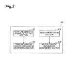
- the unit controller 60 executes a program stored in the storage, thereby realizing a yarn unevenness signal detecting section 61, a yarn unevenness/periodic unevenness determining section 62, a motor monitoring section 63 (monitoring section), and a motor periodic unevenness determining section 64.
- the yarn unevenness signal detecting section 61 is electrically connected to the yarn clearer 52 and obtains information relating to yarn unevenness output from the yarn clearer 52.
- the yarn unevenness/periodic unevenness determining section 62 obtains information output from the yarn unevenness signal detecting section 61 to determine whether periodic yarn unevenness (periodic unevenness) is formed on the spun yarn 10.
- the motor monitoring section 63 is electrically connected to the motor controller 30 and obtains information (monitor value) relating to torque of each of the motors 31 to 34 and/or information (monitor value) relating to revolution speed of each of the motors 31 to 34, output from the motor controller 30.
- the motor monitoring section 63 serves as a monitoring section that monitors at least one of the torque and the revolution speed of each of the motors 31 to 34.
- the information relating to torque of a motor can include information relating to load torque acting on the output shaft of the motor and information available to calculate the torque.
- the information relating to revolution speed of a motor can include information relating to revolution speed of the output shaft of the motor and information available to calculate the revolution speed.
- the motor periodic unevenness determining section 64 obtains information (monitor value) relating to the torque of each of the motors 31 to 34 and/or information (monitor value) relating to the revolution speed of each of the motors 31 to 34, output from the motor monitoring section 63 to determine whether there are cyclic abnormalities on the drafting rollers 16, 17, 19, and 20.
- the motor periodic unevenness determining section 64 determines that the spun yarn 10 has a periodic unevenness if a cyclic abnormality is detected on at least one of the drafting rollers 16, 17, 19, and 20.
- the motor periodic unevenness determining section 64 identifies drafting rollers among the drafting rollers 16, 17, 19, and 20 that have a cyclic abnormality. When determining that the monitor value of the motor 31 has a cyclic abnormality, the motor periodic unevenness determining section 64 determines that the back rollers 16 have a cyclic abnormality. When determining that the monitor value of the motor 32 has a cyclic abnormality, the motor periodic unevenness determining section 64 determines that the third rollers 17 have a cyclic abnormality. When determining that the monitor value of the motor 33 has a cyclic abnormality, the motor periodic unevenness determining section 64 determines that the second rollers 19 (or the apron belts 18) have a cyclic abnormality. When determining that the monitor value of the motor 34 has a cyclic abnormality, the motor periodic unevenness determining section 64 determines that the front rollers 20 have a cyclic abnormality.
- the motor periodic unevenness determining section 64 determines whether or not a cyclic abnormality appears on the drafting rollers 16, 17, 19, and 20 by performing frequency analysis on a value (monitor value) relating to at least one of the torque and the revolution speed of each of the motors 31 to 34.
- the motor periodic unevenness determining section 64 performs frequency analysis such as fast Fourier transform (FFT) calculation in order to convert a time axis into frequency.
- FFT fast Fourier transform
- the monitor periodic unevenness determining section 64 may analyze the torque and/or the revolution speed by different techniques and determine whether or not a cyclic abnormality appears on the drafting rollers 16, 17, 19, and 20.
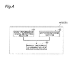
- the spinning frame 1 may include a unit controller 60B illustrated in Fig. 4 , instead of the unit controller 60 illustrated in Fig. 3 .
- the unit controller 60B illustrated in Fig. 4 differs from the unit controller 60 illustrated in Fig. 3 in that a periodic unevenness determining section 65 is included therein, instead of the yarn unevenness/periodic unevenness determining section 62 and the motor periodic unevenness determining section 63.
- the periodic unevenness determining section 65 obtains information relating to the detection result output from the yarn unevenness signal detecting section 61 and information (monitor value) relating to the torque of each of the motors 31 to 34 and/or information (monitor value) relating to the revolution speed of each of the motors 31 to 34, output from the motor monitoring section 63.
- the periodic unevenness determining section 65 detects a cyclic abnormality of the drafting rollers 16, 17, 19, and 20 on the basis of the monitor result (monitor value) from the motor monitoring section 63 and the detection result from the yarn unevenness signal detecting section 61.
- the periodic unevenness determining section 65 determines that the spun yarn 10 has a periodic unevenness if a cyclic abnormality is detected on at least one of the drafting rollers 16, 17, 19, and 20.
- the periodic unevenness determining section 65 has both functions of the yarn unevenness/periodic unevenness determining section 62 and the motor periodic unevenness determining section 63.
- the spinning frame 1 includes a displaying section 66 (notifying section) that displays the determination result from the motor periodic unevenness determining section 64 (or the periodic unevenness determining section 65).
- the displaying section 66 may be provided on the case of the motor box 5 of the spinning frame 1.
- a liquid crystal display device may be used as the displaying section 66.
- the displaying section 66 electrically connected to the unit controller 60 can display information relating to whether there is a cyclic abnormality.
- the displaying section 66 can display different information other than the display contents relating to the abnormality in the drafting rollers 16, 17, 19, and 20.
- the spinning frame 1 may include an audio outputting section instead of the displaying section 66. This configuration allows the spinning frame 1 to notify whether there is an abnormality by a voice and/or an alarm.
- a warning lamp for example, may be used as the displaying section.
- the periodic unevenness detection process is performed, for example, in a normal spinning operation.
- the unit controller 60 processes steps S11 to S 14, steps S21 to S24, steps S31 to S34, and steps S41 to S44, concurrently. These processes are performed repeatedly.
- the processing of steps S11 to S14, steps S21 to S24, steps S31 to S34, and steps S41 to S44 may be performed in this order or in a different order.
- the motor monitoring section 63 of the unit controller 60 monitors the motor 34 rotationally driving the bottom roller of the front rollers 20 to obtain the monitor value (such as torque and revolution speed) of the motor 34 (step S11).
- the motor periodic unevenness determining section 54 of the unit controller 60 obtains the monitor value of the motor 34 from the motor monitoring section 63, and performs FFT calculation on the obtained monitor value (step S 12).
- the motor periodic unevenness determining section 64 of the unit controller 60 determines whether there is a cyclic abnormality on the basis of the analysis result of the FFT calculation (step S13). For example, the motor periodic unevenness determining section 64 determines that there is a cyclic abnormality in the case where the data vary periodically (Yes at step S13). When it is determined that there is a cyclic abnormality, the process of the unit controller 60 proceeds to step S14. When it is determined that there is no cyclic abnormality (No at step S13), the process of the unit controller 60 terminates. At step S14, the motor periodic unevenness determining section 64 determines that a periodic unevenness caused by the front rollers 20 is appearing on the spun yarn 10.
- the motor monitoring section 63 of the unit controller 60 monitors the motor 33 rotationally driving the bottom roller of the second rollers 19 to obtain the monitor value (such as torque and revolution speed) of the motor 33 (step S21).
- the motor periodic unevenness determining section 54 of the unit controller 60 obtains the monitor value of the motor 33 from the motor monitoring section 63, and performs FFT calculation on the obtained monitor value (step S22).
- the motor periodic unevenness determining section 64 of the unit controller 60 determines whether there is a cyclic abnormality on the basis of the analysis result of the FFT calculation (step S23). For example, the motor periodic unevenness determining section 64 determines that there is a cyclic abnormality in the case where portions including a prominent value appear periodically (Yes at step S23). When it is determined that there is a cyclic abnormality, the process of the unit controller 60 proceeds to step S24. When it is determined that there is no cyclic abnormality (No at step S23), the process of the unit controller 60 terminates. At step S24, the motor periodic unevenness determining section 64 determines that a periodic unevenness caused by the second rollers 19 (apron belt 18) is appearing on the spun yarn 10.
- the motor monitoring section 63 of the unit controller 60 monitors the motor 32 rotationally driving the bottom roller of the third rollers 17 to obtain the monitor value (such as torque and revolution speed) of the motor 32 (step S31).
- the motor periodic unevenness determining section 54 of the unit controller 60 obtains the monitor value of the motor 32 from the motor monitoring section 63, and performs FFT calculation on the obtained monitor value (step S32).
- the motor periodic unevenness determining section 64 of the unit controller 60 determines whether there is a cyclic abnormality on the basis of the analysis result of the FFT calculation (step S33). For example, the motor periodic unevenness determining section 64 determines that there is a cyclic abnormality in the case where portions including a prominent value appear periodically (Yes at step S33), and the process proceeds to step S34. When it is determined that there is no cyclic abnormality (No at step S33), the process of the unit controller 60 terminates. At step S34, the motor periodic unevenness determining section 64 determines that a periodic unevenness caused by the third rollers 17 is appearing on the spun yarn 10.
- the motor monitoring section 63 of the unit controller 60 monitors the motor 31 rotationally driving the bottom roller of the back rollers 16 to obtain the monitor value (such as torque and revolution speed) of the motor 31 (step S41).
- the motor periodic unevenness determining section 54 of the unit controller 60 obtains the monitor value of the motor 31 from the motor monitoring section 63, and performs FFT calculation on the obtained monitor value (step S42).
- the motor periodic unevenness determining section 64 of the unit controller 60 determines whether there is a cyclic abnormality on the basis of the analysis result of the FFT calculation (step S43). For example, the motor periodic unevenness determining section 64 determines that there is a cyclic abnormality in the case where portions including a prominent value appear periodically (Yes at step S43). When it is determined that there is a cyclic abnormality, the process of the unit controller 60 proceeds to step S44. When it is determined that there is no cyclic abnormality (No at step S43), the process of the unit controller 60 terminates. At step S44, the motor periodic unevenness determining section 64 determines that a periodic unevenness caused by the back rollers 16 is appearing on the spun yarn 10.
- the unit controller 60 displays the above-mentioned determination results on the displaying section 66 after steps steps S14, S24, S34, and S44 (step S15).
- the displaying section 66 displays information relating to the determination results in accordance with signal output from the unit controller 60.
- the displaying section 66 indicates that the cause of the periodic unevenness occurred on the spun yarn 10 is the front roller 20.
- the displaying section 66 may display the drafting rollers 16, 17, 19, or 20 that are the cause of periodic unevenness, with character information.
- the displaying section 66 may display the layout of the drafting rollers 16, 17, 19, and 20, and exclusively highlight drafting rollers which are the cause of the periodic unevenness (for example, displaying in red and/or displaying in blinking).
- the displaying section 66 may display the determination result by displaying a graph of the monitor values of each of the drafting rollers 16, 17, 19, and/or 20.
- the unit controller 60 may stop the operation of the spinning unit 2, instead of displaying the result at step S15 or in addition to the result display.
- the unit controller 60 may cause the displaying section 66 to display that the drafting cradle is not closed at a proper position and/or at least one of the drafting rollers 16, 17, 19, and 20 has reached the replacement time thereof.
- the unit controller 60 can determine that at least one of the drafting rollers 16, 17, 19, and 20 includes a cyclic abnormality.
- the unit controller 60 may determine whether or not a cyclic abnormality is appearing on the basis of the yarn defect detection signal from the yarn clearer 52 after each step of S 13, S23, S33, and S43. For example, by comparing the determination result of FFT calculation and a signal from the yarn clearer 52, the unit controller 60 can precisely perform periodic unevenness detection when a determination can be made that periodic unevenness is appearing in the same cycle.
- the spinning frame 1 of the embodiment monitors the torque and/or the revolution speed of each of the motors 31 to 34 driving the respective drafting rollers 16, 17, 19, and 20 drafting the fiber band, thereby determining whether or not a cyclic abnormality appears on the drafting rollers 16, 17, 19, and 20 on the basis of the monitor results.
- This configuration enables detection of a cyclic abnormality of the drafting rollers 16, 17, 19, and 20, thereby detecting periodic unevenness on the spun yarn 10.
- the spinning frame 1 can detect periodic unevenness on the spun yarn 10 with higher precision than that by the detection of periodic unevenness using only a conventional clearer.
- the spinning frame 1 (air spinning machine) is not provided with a delivery roller and a nip roller in the above-described embodiment, the spinning machine of the present invention is not limited thereto and may be provided with the delivery roller and the nip roller.
- the delivery roller and the nip roller are arranged downstream of the spinning section 9, for example.
- the spun yarn 10 spun from the spinning section 9 is sandwiched between the delivery roller and the nip roller and transported, and wound in the winding device 13. Note that the torque and/or the revolution speed of a motor rotationally driving the delivery roller may be monitored to determine whether or not a cyclic abnormality appears on the delivery roller and/or the nip roller.
- the spinning machine is not limited to an air spinning machine, and may be different spinning machines including a drafting device.
- a ring spinning frame and a drawing frame are examples of the spinning machine.
- the motor monitoring section may monitor at least one of the torque and the revolution speed of the motor. For example, when the motor is a brushless motor, current detection for monitoring torque is not typically performed, and only revolution speed detection is performed. Thus, revolution speed is monitored in this case.
- the monitor result of the motor monitoring section 63 and the detection result of the yarn clearer 52 are both used to make determination.
- periodic unevenness may be detected only on the basis of the monitor result of the motor monitoring section 63.
- the spun yarn 10 is cut by interrupting the blow of compressed air from the nozzle in the spinning section 9 which generates swirl flow, however, other methods may be used to cut the spun yarn 10.
- the spun yarn 10 can be cut by a cutter arranged between the spinning section 9 and the yarn clearer 52.
- a yarn path is oriented from the upside to the downside in the machine height direction, but this is not limiting a configuration thereof.
- a different arrangement in which the yarn path is oriented from the downside to the upside may be possible.
- the spinning section 9 include a needle (needle-like member) to prevent a yarn twist in the spinning section 9 from propagating to the front rollers 20.
- the needle can be omitted.
- the air spinning machine may be configured such that the bottom roller of the drafting device and the traverse mechanism of the winding device of a plurality of the spinning units 2 are commonly driven (by a line shaft).
- the drafting device and/or the winding device may be provided independently in each winding unit.
- the spinning frame 1 in the above-described embodiment includes the motor controller 30 controlling the motors 31 to 34 and the unit controller 60 controlling the spinning units 2, separately.
- the unit controller 60 may control the motors.
- the motor controller 30 may serve as the determining section to determine whether there is a cyclic abnormality.
- the spinning frame 1 in the above-described embodiment includes the unit controller 60 that controls each spinning unit 2 independently. However, the unit controller 60 controlling a certain number of spinning units 2 may be provided for the spinning units 2.
- the unit controller 60 in the above-described embodiment normally monitors at least one of the torque and the revolution speed of each of the motors 31 to 34 during winding of the package 45. However, the monitoring may be performed during a specific time and, whether or not a cyclic abnormality appears on the drafting rollers 16, 17, 19, and 20 may be determined on the basis of the monitor result.
- the spinning frame 1 may be provided with a spinning test mode and monitor at least one of the torque and the revolution speed of each of the motors 31 to 34 while operating under the spinning test mode. In this case, whether or not a cyclic abnormality appears on the drafting rollers 16, 17, 19, and 20 may be determined on the basis of the monitor result. Note that, it is preferable to perform the monitoring during winding of the package 45 in order to maintain the operation efficiency of the spinning frame 1.
- the unit controller 60 in the above-described embodiment monitors at least one of the torque and the revolution speed of each of the motors 31 to 34 driving the respective drafting rollers 16, 17, 19, and 20 and determines whether there is periodic unevenness associated with each of the motors 31 to 34.
- the unit controller 60 may monitor at least one of the torque and the revolution speed of the specific motor among the motors 31 to 34 to determine whether there is periodic unevenness caused by a cyclic abnormality of the specific motor.
- the spinning frame 1 in the above-described embodiment includes a plurality of unit controllers 60 and the respective spinning units 2 are controlled by the unit controllers 60.
- the control of the spinning units 2 may be integrated and executed in the central controller.
- the present invention can be applied to a winding device as well as the spinning frame 1.
- Examples of the winding device in the present invention are a winding device in a spinning machine, and a winding device in an automatic winder.
- the automatic winder in the present embodiment illustrated in Fig. 6 includes a plurality of winder units 110 and a central controller (not illustrated) controlling the automatic winder. Note that the same explanations with those of the above-described embodiments are omitted.
- Each winder unit 110 winds a spun yarn 120 unwound from a yarn supplying bobbin 121 around a winding bobbin 122 while traversing the spun yarn 120 to form a package 130 having a certain length and a certain shape.
- the winder unit 110 includes a winding unit body 116 and a unit controller 160.
- the winding unit body 116 includes a yarn supplying section 112, a yarn tensioner 113, splicer 114 (yarn joining device), a yarn clearer 115, and a winding device 117 that are arranged in this order along the yarn running direction.
- the yarn supplying section 111 feeds the spun yarn 120 to be wound around the package 130.
- the yarn supplying section 111 includes an unwinding assisting device 112.
- the unwinding assisting device 112 lowers a restriction member 140 covering a core tube as the spun yarn 120 unwinds from the feeder bobbin 121 to assist the unwinding of the spun yarn 120 from the feeder bobbin 121.
- the yarn tensioner 113 applies certain tension to the spun yarn 120 to be wound around the package 130.
- a gate-type yarn tensioner in which movable comb teeth are arranged with respect to fixed comb teeth may be used as the yarn tensioner 113.
- the yarn tensioner 113 can apply constant tension to the spun yarn 120 to be wound, thereby improving the quality of the package 130.
- a disc-type yarn tensioner can be used as the yarn tensioner 113 instead of the above-described gate-type tensioner.
- the yarn clearer 115 monitors the quality of the spun yarn 120 to be wound around the package 130. When the yarn clearer 115 detects a yarn defect, the spun yarn 120 is cut and the yarn defect is removed.
- the yarn clearer 115 includes a clearer head 149 provided with a sensor (not illustrated) to detect a thickness of the spun yarn 120. The yarn clearer 115 detects a yarn defect by monitoring yarn thickness signals from the sensor. Near the clearer head 149, a cutter (not illustrated) is arranged to cut the spun yarn 120 immediately when the yarn clearer 115 detects a yarn defect.
- the splicer 114 joins the spun yarn 120 from the feeder bobbin 121 (lower yarn) and the spun yarn 120 from the package 130 (upper yarn) when the yarn clearer 115 cuts the yarn upon detection of a yarn defect or when the yarn unwound from the feeder bobbin 121 breaks, for example.
- a lower yarn guide pipe 125 is arranged below the splicer 114 (by the feeder bobbin 121) to capture the lower yarn from the feeder bobbin 121 and guide it to the splicer 114.
- An upper yarn guide pipe 126 is arranged above the splicer 114 (by the package 130) to capture the upper yarn from the package 130 and guide it to the splicer 114.
- the lower yarn guide pipe 125 and the upper yarn guide pipe 126 are able to swing about pivots 133 and 135, respectively.
- the tip end of the lower yarn guide pipe 125 is provided with a suction opening 132.
- the tip end of the upper yarn guide pipe 126 is provided with a suction mouth 134.
- the lower yarn guide pipe 125 and the upper yarn guide pipe 126 are each connected to an appropriate negative pressure source (not illustrated).
- the negative pressure source generates suction flows which allow the suction opening 132 and the suction mouth 134 to suck and capture the upper yarn and the lower yarn, respectively.
- the winding device 117 includes a cradle 123 rotationally supporting the package 130, a winding drum 124 (rotary drum, rotary body) rotating the package 130 while making contact with the package 130, a motor 153 rotationally driving the winding drum 124, and a motor controller 154 controlling the rotation of the motor 153.
- the winding drum 124 is provided with traversing grooves 127 for traversing the spun yarn 120 with respect to the package 130. With this configuration, the winder unit 110 can wind the spun yarn 120 around the package 130 while traversing the spun yarn 120.
- the motor controller 154 is electrically connected to the motor 153.
- the motor controller 154 detects load torque acting on the motor 153.
- the motor controller 154 detects the revolution speed of the output shaft of the motor 153. It is enough for the motor controller 154 to be capable of detecting at least one of the torque and the revolution speed.
- the motor controller 154 outputs data relating to the torque and/or the revolution speed of a motor 154 to the unit controller 160.
- the unit controller 160 can detect cyclic abnormalities on the winding drum 124.
- the unit controller 160 (controller) includes a CPU performing arithmetic processing, a ROM and a RAM each serving as a storage, an input signal circuit, an output signal circuit, and a power supply circuit, for example.
- the unit controller 160 executes a program stored in the storage, thereby realizing a motor monitoring section 163 (monitoring section), and a determining section 164.
- the motor monitoring section 163 is electrically connected to the motor controller 154 and obtains information (monitor value) relating to the torque of the motor 153 and/or information (monitor value) relating to the revolution speed of the motor 153, output from the motor controller 154.
- the motor monitoring section 163 serves as a monitoring section that monitors at least one of the torque and the revolution speed of the motor 153.
- the determining section 164 determines whether or not a cyclic abnormality appears on the winding drum 124 by performing frequency analysis on a value (monitor value) relating to at least one of the torque and the revolution speed of the motor 153.
- the determining section 164 performs frequency analysis such as fast Fourier transform (FFT) calculation in order to convert a time axis into frequency.
- FFT fast Fourier transform
- the determining section 164 may analyze the torque and/or the revolution speed by different techniques and determine whether or not a cyclic abnormality appears on the winding drum 124.
- the automatic winder includes a displaying section 66 (notifying section) displaying the determination result of the determining section 164.
- the displaying section 66 electrically connected to the unit controller 160 can display information relating to whether there is a cyclic abnormality.
- the displaying section 66 can display different information other than the display contents relating to the abnormality in the winding drum 124.
- the winding device 117 in the automatic winder determines whether or not a cyclic abnormality appears on the motor 153 by monitoring at least one of the torque and the revolution speed of the motor 153, thereby detecting the cyclic abnormality of the winding drum 124.
- an abnormality such as eccentricity of the package 130 can be detected in an early stage.
- the winding device 117 may include a traverse mechanism separate from a winding drum 124, instead of the winding drum 124 on which the traversing grooves 127 are formed, similarly to the winding device 13 of the spinning frame 1.
- the monitoring section of the winding device monitors at least one of the torque and the revolution speed of the motor rotationally driving a winding drum having no traversing grooves.
- the package 130 instead of the winding drum, may be rotationally driven directly.
- the monitoring section monitors at least one of the torque and the revolution speed of a motor directly rotationally driving the package 130.
- the configuration may be suitable for a textile machine provided with a motor driving a rotary body, in which a cyclic abnormality of the rotary body can be determined by monitoring at least one of the load torque acting on the motor and the revolution speed of the motor.
- Such a textile machine includes a rotary body transporting the fiber band, a motor rotationally driving the rotary body, a monitoring section monitoring at least one of torque and revolution speed of the motor, and a determining section determining a cyclic abnormality appearing on the rotary body on the basis of the monitor result of the monitoring section.
- the determining section of the textile machine may perform frequency analysis on a value relating to at least one of the torque and the revolution speed that are each the monitor result of the monitoring section to determine the cyclic abnormality of the rotary body.
- the textile machine may further include a notifying section notifying information relating to the monitor result of the monitoring section.
- Such a textile machine determines whether or not a cyclic abnormality appears on the rotary body by monitoring at least one of the torque and the revolution speed of the motor, thereby detecting a periodic abnormality on the fiber band processed by the rotary body.
- a spinning machine of the present invention is capable of detecting a cyclic abnormality of a drafting roller and improving detection accuracy of such an abnormality.
- a winding device of the present invention is capable of detecting a cyclic abnormality of a rotary drum and improving detection accuracy of such an abnormality.
- a textile machine of the present invention is capable of detecting a cyclic abnormality of a rotary body and improving detection accuracy of such an abnormality.
Landscapes
- Engineering & Computer Science (AREA)
- Mechanical Engineering (AREA)
- Textile Engineering (AREA)
- Quality & Reliability (AREA)
- Spinning Or Twisting Of Yarns (AREA)
Abstract
Description
- The present invention relates to a spinning machine, a winding device, and a textile machine.
- A textile machine described in
Patent Literature 1 has been conventionally known as a technique in such a field. The technique described inPatent Literature 1 digitizes a yarn unevenness electric signal obtained from a yarn unevenness detector (for example, a clearer) installed on a textile machine such as a spinning frame, and analyzes the digitized signal with a calculator, thereby detecting yarn unevenness. - In addition, a technique described in
Patent Literature 2 has been known as an abnormality detection method for a drafting device in a spinning machine. With this technique, variation in load torque acting on a driving motor that drives a drafting roller is monitored, and the operation of the drafting device is stopped if it is determined that there is an abnormality because the variation of the load torque exceeded a certain rate. -
- Patent Literature 1: Japanese Patent Application Laid-Open Publication No.
58-62511 - Patent Literature 2: Japanese Patent Application Laid-Open Publication No.
2003-166135 - The technique described in
Patent Literature 1 may fail to detect relatively long-periodic unevenness if an unevenness detector has insufficient detection accuracy. The technique described inPatent Literature 2 monitors variation in load torque on a motor, but does not detect a cyclic abnormality. - An object of the present invention is to provide a spinning machine that is capable of detecting a cyclic abnormality of a drafting roller and improving detection accuracy of such an abnormality.
- The present invention aims to provide a winding device that is capable of detecting a cyclic abnormality of a rotary drum and improving detection accuracy of such an abnormality.
- The present invention aims to provide a textile machine that is capable of detecting a cyclic abnormality of a rotary body and improving detection accuracy of such an abnormality.
- A spinning machine includes: a drafting roller drafting a fiber band; a motor rotationally driving the drafting roller; a monitoring section monitoring at least one of torque and revolution speed of the motor; and a periodic unevenness determining section determining a cyclic abnormality of the drafting roller that appears as periodic unevenness on the fiber band, on the basis of a monitor result of the monitoring section.
- This spinning machine monitors at least one of the torque and the revolution speed of the motor driving the drafting roller that drafts the fiber band, determining whether or not a cyclic abnormality appears on the drafting roller on the basis of the monitor result. With this configuration, the cyclic abnormality of the drafting roller that appears as periodic unevenness on the fiber band can be detected, and a cyclic abnormality of the drafted fiber band can be detected. Using a conventional unevenness detector (clearer) commonly installed on a spinning machine may fail to detect long-periodic unevenness. The values of torque and/or revolution speed (monitor value) of the motor can be detected precisely. Thus, the periodic unevenness determining section can determine the periodic abnormality on the fiber band in higher accuracy than the clearer, on the basis of the monitor value obtained by monitoring the motor.
- The periodic unevenness determining section may perform frequency analysis on a value relating to at least one of the torque and the revolution that are each the monitor result of the monitoring section to determine the cyclic abnormality of the drafting roller. The frequency analysis is effective means for determining a cyclic abnormality, thus the cyclic abnormality of the drafting roller can be detected precisely.
- The spinning machine may include a plurality of such drafting rollers arranged along a transporting direction of the fiber band, and a plurality of such motors independently driving the drafting rollers. The periodic unevenness determining section may determine which motor out of the motors has cyclic abnormalities, on the basis of the monitor result of the monitoring section. With this configuration, the periodic unevenness determining section can reliably identify which drafting roller among the drafting rollers has a cause of a periodic unevenness. It is difficult to determine the drafting roller causing the periodic unevenness with unevenness detection using a conventional clearer in the case where multiple periodic unevenness occurs in an overlapping manner.
- The spinning machine may further include a periodic unevenness detecting section disposed on a downstream of the drafting roller. The periodic unevenness detecting section may detect unevenness on the fiber band drafted with the drafting roller. The periodic unevenness determining section may determine a cyclic abnormality of the drafting roller on the basis of the monitor result of the monitoring section and a detection result of the unevenness detecting section to detect the periodic unevenness on the fiber band. The periodic unevenness determining section can precisely detect the cyclic abnormality of the drafting rollers on the basis of the monitor result on the motors driving the drafting rollers and the detection result of the unevenness on the fiber band detected by the unevenness detecting section.
- The spinning machine may further include a notifying section notifying information relating to the monitor result of the monitoring section. An operator can easily check for a cyclic abnormality of the drafting rollers and promptly take an appropriate action, on the basis of the information notified by the notifying section. Examples of the notifying section are a displaying section and an audio outputting section. In the case where the notifying section is the displaying section, the operator can easily check the cyclic abnormality by looking at the displaying section.
- The spinning machine may further include: an air spinning device spinning the fiber band drafted with the drafting roller, with swirl flows; and a winding device winding the fiber band spun from the air spinning device into a package. The periodic unevenness determining section may determine a cyclic abnormality of the drafting roller while the winding device winds the fiber band into the package.
- The periodic unevenness determining section can determine a cyclic abnormality of the drafting rollers even while the winding device winds the fiber band into the package. Thus, decrease in operating efficiency of the spinning machine can be reduced.
- A windier includes: a rotary drum making contacting with and rotating a winding package to cause the winding package to wind a yarn; a motor rotationally driving the rotary drum; a monitoring section monitoring at least one of torque and revolution speed of the motor; and a determining section determining a cyclic abnormality of the rotary drum on the basis of a monitor result of the monitoring section.
- This winding device monitors at least one of the torque and the revolution speed of the motor driving the rotary drum, determining whether or not a cyclic abnormality appears on the rotary drum on the basis of the monitor result. With this configuration, the cyclic abnormality of the rotary drum can be detected to ensure detection of an abnormality such as eccentricity of the winding package, therefore, the reliability of the winding device can be improved. Examples of the winding device are a winding device in a spinning machine, and an automatic winder.
- The determining section may perform frequency analysis on a value relating to at least one of the torque and the revolution speed that are each the monitor result of the monitoring section to determine the cyclic abnormality of the rotary drum. The frequency analysis is effective means for determining a cyclic abnormality, thus the cyclic abnormality of the rotary drum can be detected precisely.
- The winding device may further include: a notifying section notifying information relating to the monitor result of the monitoring section. The operator can easily check a cyclic abnormality of the drafting rollers and promptly take an appropriate action, on the basis of the information notified by the notifying section. Examples of the notifying section are a displaying section and an audio outputting section. In the case where the notifying section is the displaying section, the operator can easily check the cyclic abnormality by looking at the displaying section.
- A textile machine includes: a rotary body transporting a fiber band; a motor rotationally driving the rotary body; a monitoring section monitoring at least one of torque and revolution speed of the motor; and a determining section determining a cyclic abnormality of the rotary body on the basis of a monitor result of the monitoring section.
- This textile machine monitors at least one of the torque and the revolution speed of the motor driving the rotary body that transports the fiber band, determining whether or not a cyclic abnormality appears on the rotary body on the basis of the monitor result. Note that "a rotary body transporting a fiber band" includes a device transporting a fiber band and other devices capable of performing certain processing, such as "drafting a fiber band (sliver)" and/or "winding a yarn", accompanying the rotation of the rotary body.
- For example, in the case where a fiber band (including a sliver and a yarn) moving accompanying the rotation of the rotary body has a defect such as a periodically changing thickness, load torque acting on the motor varies, and the revolution speed of the motor varies. Thus, whether or not a cyclic abnormality appears on the rotary body is determined by monitoring at least one of the torque and the revolution speed of the motor, thereby detecting the periodic abnormality on the fiber band processed by the rotary body. This makes it possible to detect long-periodic unevenness which is difficult to be detected by a conventional unevenness detector (clearer).
- The determining section may perform frequency analysis on a value relating to at least one of the torque and the revolution speed that are each the monitor result of the monitoring section to determine the cyclic abnormality of the rotary body. The frequency analysis is effective means for determining a cyclic abnormality, thus the cyclic abnormality of the rotary body can be detected precisely.
- The textile machine may further include: a notifying section notifying information relating to the monitor result of the monitoring section. The operator can easily check a cyclic abnormality of the rotary body and promptly take an appropriate action, on the basis of the information notified by the notifying section. Examples of the notifying section are a displaying section and an audio outputting section. In the case where the notifying section is the displaying section, the operator can easily check the cyclic abnormality by looking at the displaying section.
- A spinning machine of the present invention is capable of detecting a cyclic abnormality of a drafting roller and improving detection accuracy of such an abnormality.
- A winding device of the present invention is capable of detecting a cyclic abnormality of a rotary drum and improving detection accuracy of such an abnormality.
- A textile machine of the present invention is capable of detecting a cyclic abnormality of a rotary body and improving detection accuracy of such an abnormality.
-
- [
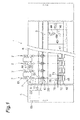
Fig. 1] Fig. 1 is a front view of a spinning frame of an embodiment of the present invention. - [
Fig. 2] Fig. 2 is a longitudinal sectional view of the spinning frame illustrated inFig. 1 . - [
Fig. 3] Fig. 3 is a block configuration diagram illustrating a unit controller in a spinning unit of a first embodiment of the present invention. - [
Fig. 4] Fig. 4 is a block configuration diagram illustrating the unit controller in the spinning unit of a second embodiment of the present invention. - [
Fig. 5] Fig. 5 is a flow chart illustrating a procedure executed in a periodic unevenness detection process. - [
Fig. 6] Fig. 6 is a schematic configuration diagram illustrating a winding unit in an automatic winder of a third embodiment of the present invention. - A spinning frame (spinning machine) according to an embodiment of the present invention is described with reference to the accompanying drawings. Note that an "upstream" and a "downstream" in this description mean the upstream and the downstream in a running direction of a yarn during spinning, respectively.
- A
spinning frame 1 illustrated inFig. 1 andFig. 2 includes a plurality of spinningunits 2 aligned next to each other. Thespinning frame 1 includes ayarnm joining carriage 3 capable of running along the aligning direction of thespinning units 2, amotor box 5, a central controller (not illustrated) controlling thespinning frame 1, and unit controllers 60 (refer toFig. 3 andFig. 4 ) controlling thespinning units 2. - For example, the central controller may be installed in the
motor box 5. The central controller is electrically connected to themultiple unit controllers 60 to integrally control theunit controllers 60. Theunit controller 60 is provided to eachspinning unit 2 to independently control the spinning unit 2 (will be described in detail later). - Each spinning unit 2 (spinning machine) includes a
drafting device 7, a spinning section 9 (air spinning device), ayarn clearer 52, a yarn slack-eliminating device 12 (yarn storage device), and a windingdevice 13, in this order from upstream to downstream. Thedrafting device 7 is provided near the top end of acase 6 of thespinning frame 1. Afiber band 8 fed from thedrafting device 7 is supplied to thespinning section 9 to be spun. A spunyarn 10 that has been spun by thespinning section 9 passes through theyarn clearer 52. Thereafter, the spunyarn 10 is fed by the yarn slack-eliminatingdevice 12 and wound by the windingdevice 13, whereby apackage 45 is formed. - The
drafting device 7 drafts asliver 15 to obtain afiber band 8. Thedrafting device 7 includes a plurality of pairs of draftingrollers fiber band 8 and drafts thefiber band 8 with the draftingrollers Fig. 2 , thedrafting device 7 includes backrollers 16,third rollers 17,second rollers 19 around whichapron belts 18 are wound, andfront rollers 20, serving as the draftingrollers rollers sliver 15. - The
drafting device 7 includes a drafting cradle (not illustrated). The drafting cradle supports the top rollers and opens and closes by swinging about a certain pivot. Under a state in which the drafting cradle is closed, the top rollers make contact with the bottom rollers, and thedrafting device 7 drafts thefiber band 8. If the drafting cradle is not closed at a proper position, a periodic unevenness can be generated on thefiber band 8. - The
drafting device 7 includesmotors 31 to 34 to drive the bottom rollers of the draftingrollers motor 31 rotationally drives theback roller 16. Themotor 32 rotationally drives thethird roller 17. Themotor 33 rotationally drives thesecond roller 19. Themotor 34 rotationally drives thefront roller 20. Although a single motor rotationally drives a single drafting roller in the present embodiment, a single motor may rotationally drive a plurality of drafting rollers. For example, a single motor may rotationally drive theback roller 16 and thethird roller 17 which are drafting rollers in a low-speed side. - The top rollers of the drafting
rollers motors 31 to 34. - The
spinning unit 2 includes amotor controller 30 that controls the rotation of themotors 31 to 34. Themotor controller 30 is electrically connected to themotors 31 to 34. Themotor controller 30 can detect load torque acting on each of themotors 31 to 34. Themotor controller 30 can detect the revolution speed of the output shaft of each of themotors 31 to 34. It is enough for themotor controller 30 to be capable of detecting at least one of the torque and the revolution speed. Themotor controller 30 outputs data relating to the torque and/or the revolution speed of each of the motor s 31 to 34 to theunit controller 60. - The detailed structure of the
spinning section 9 is not illustrated, but the present embodiment employs a pneumatic structure using swirling air flow (swirl flow) to twist thefiber band 8, so as to produce a spunyarn 10. - The yarn slack-eliminating
device 12 applies certain tension to the spunyarn 10 and draws the spunyarn 10 from thespinning section 9. The yarn slack-eliminatingdevice 12 prevents the spunyarn 10 from slacking by storing the spunyarn 10 fed out from thespinning section 9 when theyarn joining carriage 3 performs yarn joining. The yarn slack-eliminatingdevice 12 adjusts the tension of the spunyarn 10 so as to prevent the variation in the tension of the spunyarn 10 at the windingdevice 13 from propagating to thespinning section 9. - The yarn slack-eliminating
device 12 includes a slack eliminating roller (yarn storage roller) 21, ayarn hooking member 22, anupstream guide 23, anelectric motor 25, adownstream guide 26, and a yarnstorage amount sensor 27. - The
yarn hooking member 22 is configured to hook the spunyarn 10. Theyarn hooking member 22 hooked with the spunyarn 10 integrally rotates with theslack eliminating roller 21, thereby winding the spunyarn 10 on an outer peripheral surface of theslack eliminating roller 21. - The
slack eliminating roller 21 winds a certain amount of the spunyarn 10 around the outer peripheral surface thereof to store the spunyarn 10. Theslack eliminating roller 21 is rotationally driven by theelectric motor 25. Rotation of theslack eliminating roller 21 tightens the spunyarn 10 wound around the outer peripheral surface of theslack eliminating roller 21, thereby drawing the spunyarn 10 from the upstream of the yarn slack-eliminatingdevice 12. That is, when the spunyarn 10 is wound around the outer peripheral surface of theslack eliminating roller 21, rotation of theslack eliminating roller 21 in a certain revolution speed applies certain tension to the spunyarn 10 and draws the spunyarn 10 out from thespinning section 9 at a certain speed, thereby transporting the spunyarn 10 to the downstream at a certain speed. - A certain contact area can be obtained between the
slack eliminating roller 21 and the spunyarn 10 by winding the certain amount of the spunyarn 10 around the outer peripheral surface of theslack eliminating roller 21. This configuration enables theslack eliminating roller 21 to hold and draw the spunyarn 10 with sufficient strength. Thus, the spunyarn 10 can be drawn out from thespinning section 9 at a stable speed without causing slip for example. As illustrated inFig. 2 , since there is no additional component (such as a conventional delivery roller) applying the tension to the spunyarn 10 between thespinning section 9 and the slack-eliminatingdevice 12, the revolution speed of theslack eliminating roller 21 determines the speed of the spunyarn 10 drawn out from thespinning section 9. Consequently, thespinning frame 1 of the present embodiment applies the tension to the spunyarn 10 with the slack-eliminatingdevice 12, thereby drawing out the spunyarn 10 from thespinning section 9 at an accurate speed with less variation. - The yarn
storage amount sensor 27 detects a storage amount of the spunyarn 10 stored on theslack eliminating roller 21 in a non-contact manner and sends the detected storage amount to theunit controller 60. - The
upstream guide 23 is arranged slightly upstream of theslack eliminating roller 21. Theupstream guide 23 properly guides the spunyarn 10 to the outer peripheral surface of theslack eliminating roller 21. Theupstream guide 23 prevents a twist of the spunyarn 10 propagating from thespinning section 9 from being propagated to the downstream of theupstream guide 23. - The
yarn clearer 52 is provided between thespinning section 9 and the slack-eliminatingdevice 12, in the front face side of thecase 6 of thespinning frame 1. The spunyarn 10 spun in thespinning section 9 passes through theyarn clearer 52 before being wound by the slack-eliminatingdevice 12. Theyarn clearer 52 monitors the thickness of the spunyarn 10 running therethrough and sends a yarn defect detection signal to the unit controller 60 (controller) if a yarn defect on the spunyarn 10 is detected. Theyarn clearer 52 is arranged downstream of thedrafting device 7 and serves as an unevenness detecting section detecting unevenness on thefiber band 8 drafted with thedrafting device 7. - In the case where a yarn defect is detected and yarns are to be joined, the
unit controller 60 stops thedrafting device 7, thespinning section 9, and other devices, in a certain timing. In this case, theunit controller 60 cuts the spunyarn 10 by interrupting the blow of compressed air from a nozzle in thespinning section 9 which generates swirl flow. - The
unit controller 60 sends a control signal to theyarn joining carriage 3 to move theyarn joining carriage 3 to the front of therelevant spinning unit 2. Thereafter, theunit controller 60 drives thespinning section 9 and other devices again, causes theyarn joining carriage 3 to perform yarn joining, and restarts winding. In this case, the yarn slack-eliminatingdevice 12 eliminates slack on the spunyarn 10 by storing the spunyarn 10 continuously fed out from thespinning section 9 on theslack eliminating roller 21 during a period from the restart of spinning in thespinning section 9 to the restart of winding. - The
yarn joining carriage 3 includes a splicer (yarn joining device) 43, asuction pipe 44, and asuction mouth 46. When a yarn breakage or a yarn cut has occurred in onespinning unit 2, theyarn joining carriage 3 travels on arail 41 to therelevant spinning unit 2 and stops there. Thesuction pipe 44 swings up and down about a pivot, sucks and catches a yarn end fed out from thespinning section 9, and guides it to thesplicer 43. Thesuction mouth 46 swings up and down about a pivot, sucks and catches a yarn end from thepackage 45 supported with the windingdevice 13, and guides it to thesplicer 43. Thesplicer 43 joins the yarn ends guided thereto. - The winding
device 13 includes acradle arm 71 supported to be able to swing about apivot 70. Thecradle arm 71 rotationally supports abobbin 48 for winding the spunyarn 10. - The winding
device 13 includes a winding drum 72 (rotary drum), and atraverse device 75. The windingdrum 72 can drive while making contact with an outer circumferential surface of thebobbin 48 or thepackage 45. Thetraverse device 75 includes atraverse guide 76 that can hook the spunyarn 10. While reciprocating thetraverse guide 76 using unillustrated driving means, the windingdevice 13 drives the windingdrum 72 with an electric motor (not illustrated) for rotating thepackage 45 making contact with the windingdrum 72, thereby winding the spunyarn 10 while traversing the spunyarn 10.Fig. 1 illustrates the windingdevice 13 that is configured to wind thecylindrical package 45. The windingdevice 13, however, may be configured to wind a conical package. - The
spinning frame 1 may be configured to rotationally drive the windingdrums 72 of thespinning units 2 using a common electric motor or configured to provide eachspinning unit 2 with a dedicated electric motor and rotationally drive each windingdrum 72 independently. - The
unit controller 60 can detect cyclic abnormalities on the draftingrollers unit controller 60 executes a program stored in the storage, thereby realizing a yarn unevennesssignal detecting section 61, a yarn unevenness/periodicunevenness determining section 62, a motor monitoring section 63 (monitoring section), and a motor periodicunevenness determining section 64. - The yarn unevenness
signal detecting section 61 is electrically connected to theyarn clearer 52 and obtains information relating to yarn unevenness output from theyarn clearer 52. The yarn unevenness/periodicunevenness determining section 62 obtains information output from the yarn unevennesssignal detecting section 61 to determine whether periodic yarn unevenness (periodic unevenness) is formed on the spunyarn 10. - The
motor monitoring section 63 is electrically connected to themotor controller 30 and obtains information (monitor value) relating to torque of each of themotors 31 to 34 and/or information (monitor value) relating to revolution speed of each of themotors 31 to 34, output from themotor controller 30. Themotor monitoring section 63 serves as a monitoring section that monitors at least one of the torque and the revolution speed of each of themotors 31 to 34. The information relating to torque of a motor can include information relating to load torque acting on the output shaft of the motor and information available to calculate the torque. The information relating to revolution speed of a motor can include information relating to revolution speed of the output shaft of the motor and information available to calculate the revolution speed. - The motor periodic
unevenness determining section 64 obtains information (monitor value) relating to the torque of each of themotors 31 to 34 and/or information (monitor value) relating to the revolution speed of each of themotors 31 to 34, output from themotor monitoring section 63 to determine whether there are cyclic abnormalities on the draftingrollers unevenness determining section 64 determines that the spunyarn 10 has a periodic unevenness if a cyclic abnormality is detected on at least one of the draftingrollers - The motor periodic
unevenness determining section 64 identifies drafting rollers among the draftingrollers motor 31 has a cyclic abnormality, the motor periodicunevenness determining section 64 determines that theback rollers 16 have a cyclic abnormality. When determining that the monitor value of themotor 32 has a cyclic abnormality, the motor periodicunevenness determining section 64 determines that thethird rollers 17 have a cyclic abnormality. When determining that the monitor value of themotor 33 has a cyclic abnormality, the motor periodicunevenness determining section 64 determines that the second rollers 19 (or the apron belts 18) have a cyclic abnormality. When determining that the monitor value of themotor 34 has a cyclic abnormality, the motor periodicunevenness determining section 64 determines that thefront rollers 20 have a cyclic abnormality. - The motor periodic
unevenness determining section 64 determines whether or not a cyclic abnormality appears on the draftingrollers motors 31 to 34. The motor periodicunevenness determining section 64 performs frequency analysis such as fast Fourier transform (FFT) calculation in order to convert a time axis into frequency. The monitor periodicunevenness determining section 64 may analyze the torque and/or the revolution speed by different techniques and determine whether or not a cyclic abnormality appears on the draftingrollers - The
spinning frame 1 may include aunit controller 60B illustrated inFig. 4 , instead of theunit controller 60 illustrated inFig. 3 . Theunit controller 60B illustrated inFig. 4 differs from theunit controller 60 illustrated inFig. 3 in that a periodicunevenness determining section 65 is included therein, instead of the yarn unevenness/periodicunevenness determining section 62 and the motor periodicunevenness determining section 63. - The periodic
unevenness determining section 65 obtains information relating to the detection result output from the yarn unevennesssignal detecting section 61 and information (monitor value) relating to the torque of each of themotors 31 to 34 and/or information (monitor value) relating to the revolution speed of each of themotors 31 to 34, output from themotor monitoring section 63. The periodicunevenness determining section 65 detects a cyclic abnormality of the draftingrollers motor monitoring section 63 and the detection result from the yarn unevennesssignal detecting section 61. The periodicunevenness determining section 65 determines that the spunyarn 10 has a periodic unevenness if a cyclic abnormality is detected on at least one of the draftingrollers unevenness determining section 65 has both functions of the yarn unevenness/periodicunevenness determining section 62 and the motor periodicunevenness determining section 63. - The
spinning frame 1 includes a displaying section 66 (notifying section) that displays the determination result from the motor periodic unevenness determining section 64 (or the periodic unevenness determining section 65). The displayingsection 66 may be provided on the case of themotor box 5 of thespinning frame 1. A liquid crystal display device may be used as the displayingsection 66. In accordance with signals from theunit controller 60, the displayingsection 66 electrically connected to theunit controller 60 can display information relating to whether there is a cyclic abnormality. Thus, the operator can easily check for a cyclic abnormality by looking at the display contents on the displayingsection 66. The displayingsection 66 can display different information other than the display contents relating to the abnormality in the draftingrollers - The
spinning frame 1 may include an audio outputting section instead of the displayingsection 66. This configuration allows thespinning frame 1 to notify whether there is an abnormality by a voice and/or an alarm. A warning lamp, for example, may be used as the displaying section. - Next, a periodic unevenness detection process is described with reference to
Fig. 5 . The periodic unevenness detection process is performed, for example, in a normal spinning operation. As illustrated inFig. 5 , theunit controller 60 processes steps S11 to S 14, steps S21 to S24, steps S31 to S34, and steps S41 to S44, concurrently. These processes are performed repeatedly. The processing of steps S11 to S14, steps S21 to S24, steps S31 to S34, and steps S41 to S44 may be performed in this order or in a different order. - The following describes the processing of steps S11 to S14. First, the
motor monitoring section 63 of theunit controller 60 monitors themotor 34 rotationally driving the bottom roller of thefront rollers 20 to obtain the monitor value (such as torque and revolution speed) of the motor 34 (step S11). Next, the motor periodic unevenness determining section 54 of theunit controller 60 obtains the monitor value of themotor 34 from themotor monitoring section 63, and performs FFT calculation on the obtained monitor value (step S 12). - Thereafter, the motor periodic
unevenness determining section 64 of theunit controller 60 determines whether there is a cyclic abnormality on the basis of the analysis result of the FFT calculation (step S13). For example, the motor periodicunevenness determining section 64 determines that there is a cyclic abnormality in the case where the data vary periodically (Yes at step S13). When it is determined that there is a cyclic abnormality, the process of theunit controller 60 proceeds to step S14. When it is determined that there is no cyclic abnormality (No at step S13), the process of theunit controller 60 terminates. At step S14, the motor periodicunevenness determining section 64 determines that a periodic unevenness caused by thefront rollers 20 is appearing on the spunyarn 10. - The following describes the processing of steps S21 to S24. First, the
motor monitoring section 63 of theunit controller 60 monitors themotor 33 rotationally driving the bottom roller of thesecond rollers 19 to obtain the monitor value (such as torque and revolution speed) of the motor 33 (step S21). Next, the motor periodic unevenness determining section 54 of theunit controller 60 obtains the monitor value of themotor 33 from themotor monitoring section 63, and performs FFT calculation on the obtained monitor value (step S22). - Thereafter, the motor periodic
unevenness determining section 64 of theunit controller 60 determines whether there is a cyclic abnormality on the basis of the analysis result of the FFT calculation (step S23). For example, the motor periodicunevenness determining section 64 determines that there is a cyclic abnormality in the case where portions including a prominent value appear periodically (Yes at step S23). When it is determined that there is a cyclic abnormality, the process of theunit controller 60 proceeds to step S24. When it is determined that there is no cyclic abnormality (No at step S23), the process of theunit controller 60 terminates. At step S24, the motor periodicunevenness determining section 64 determines that a periodic unevenness caused by the second rollers 19 (apron belt 18) is appearing on the spunyarn 10. - The following describes the processing of steps S31 to S34. The
motor monitoring section 63 of theunit controller 60 monitors themotor 32 rotationally driving the bottom roller of thethird rollers 17 to obtain the monitor value (such as torque and revolution speed) of the motor 32 (step S31). Next, the motor periodic unevenness determining section 54 of theunit controller 60 obtains the monitor value of themotor 32 from themotor monitoring section 63, and performs FFT calculation on the obtained monitor value (step S32). - Thereafter, the motor periodic
unevenness determining section 64 of theunit controller 60 determines whether there is a cyclic abnormality on the basis of the analysis result of the FFT calculation (step S33). For example, the motor periodicunevenness determining section 64 determines that there is a cyclic abnormality in the case where portions including a prominent value appear periodically (Yes at step S33), and the process proceeds to step S34. When it is determined that there is no cyclic abnormality (No at step S33), the process of theunit controller 60 terminates. At step S34, the motor periodicunevenness determining section 64 determines that a periodic unevenness caused by thethird rollers 17 is appearing on the spunyarn 10. - The following describes the processing of steps S41 to S44. The
motor monitoring section 63 of theunit controller 60 monitors themotor 31 rotationally driving the bottom roller of theback rollers 16 to obtain the monitor value (such as torque and revolution speed) of the motor 31 (step S41). Next, the motor periodic unevenness determining section 54 of theunit controller 60 obtains the monitor value of themotor 31 from themotor monitoring section 63, and performs FFT calculation on the obtained monitor value (step S42). - Thereafter, the motor periodic
unevenness determining section 64 of theunit controller 60 determines whether there is a cyclic abnormality on the basis of the analysis result of the FFT calculation (step S43). For example, the motor periodicunevenness determining section 64 determines that there is a cyclic abnormality in the case where portions including a prominent value appear periodically (Yes at step S43). When it is determined that there is a cyclic abnormality, the process of theunit controller 60 proceeds to step S44. When it is determined that there is no cyclic abnormality (No at step S43), the process of theunit controller 60 terminates. At step S44, the motor periodicunevenness determining section 64 determines that a periodic unevenness caused by theback rollers 16 is appearing on the spunyarn 10. - The
unit controller 60 displays the above-mentioned determination results on the displayingsection 66 after steps steps S14, S24, S34, and S44 (step S15). The displayingsection 66 displays information relating to the determination results in accordance with signal output from theunit controller 60. For example, the displayingsection 66 indicates that the cause of the periodic unevenness occurred on the spunyarn 10 is thefront roller 20. The displayingsection 66 may display the draftingrollers section 66 may display the layout of the draftingrollers section 66 may display the determination result by displaying a graph of the monitor values of each of the draftingrollers - If it is determined that any one of the drafting
rollers spinning unit 2, instead of displaying the result at step S15 or in addition to the result display. As mentioned above, in the case where theunit controller 60 stops the operation of thespinning unit 2, theunit controller 60 may cause the displayingsection 66 to display that the drafting cradle is not closed at a proper position and/or at least one of the draftingrollers rollers unit controller 60 can determine that at least one of the draftingrollers - Note that, the
unit controller 60 may determine whether or not a cyclic abnormality is appearing on the basis of the yarn defect detection signal from theyarn clearer 52 after each step ofS 13, S23, S33, and S43. For example, by comparing the determination result of FFT calculation and a signal from theyarn clearer 52, theunit controller 60 can precisely perform periodic unevenness detection when a determination can be made that periodic unevenness is appearing in the same cycle. - The
spinning frame 1 of the embodiment monitors the torque and/or the revolution speed of each of themotors 31 to 34 driving therespective drafting rollers rollers rollers yarn 10. Thespinning frame 1 can detect periodic unevenness on the spunyarn 10 with higher precision than that by the detection of periodic unevenness using only a conventional clearer. - The present invention is described on the basis of an embodiment thereof, but is not limited to the embodiment.
- Although the spinning frame 1 (air spinning machine) is not provided with a delivery roller and a nip roller in the above-described embodiment, the spinning machine of the present invention is not limited thereto and may be provided with the delivery roller and the nip roller. The delivery roller and the nip roller are arranged downstream of the
spinning section 9, for example. The spunyarn 10 spun from thespinning section 9 is sandwiched between the delivery roller and the nip roller and transported, and wound in the windingdevice 13. Note that the torque and/or the revolution speed of a motor rotationally driving the delivery roller may be monitored to determine whether or not a cyclic abnormality appears on the delivery roller and/or the nip roller. - The spinning machine is not limited to an air spinning machine, and may be different spinning machines including a drafting device. A ring spinning frame and a drawing frame are examples of the spinning machine.
- The motor monitoring section (monitoring section) may monitor at least one of the torque and the revolution speed of the motor. For example, when the motor is a brushless motor, current detection for monitoring torque is not typically performed, and only revolution speed detection is performed. Thus, revolution speed is monitored in this case.
- In the detection of periodic unevenness in the above-described embodiment, the monitor result of the
motor monitoring section 63 and the detection result of theyarn clearer 52 are both used to make determination. However, periodic unevenness may be detected only on the basis of the monitor result of themotor monitoring section 63. - In the above-described embodiment, when a yarn defect is detected and yarns are to be joined, the spun
yarn 10 is cut by interrupting the blow of compressed air from the nozzle in thespinning section 9 which generates swirl flow, however, other methods may be used to cut the spunyarn 10. For example, the spunyarn 10 can be cut by a cutter arranged between thespinning section 9 and theyarn clearer 52. - In the above-described air spinning machine, a yarn path is oriented from the upside to the downside in the machine height direction, but this is not limiting a configuration thereof. For example, a different arrangement in which the yarn path is oriented from the downside to the upside may be possible.
- It is preferable that the
spinning section 9 include a needle (needle-like member) to prevent a yarn twist in thespinning section 9 from propagating to thefront rollers 20. However, the needle can be omitted. - The air spinning machine may be configured such that the bottom roller of the drafting device and the traverse mechanism of the winding device of a plurality of the
spinning units 2 are commonly driven (by a line shaft). In the air spinning machine, the drafting device and/or the winding device may be provided independently in each winding unit. - The
spinning frame 1 in the above-described embodiment includes themotor controller 30 controlling themotors 31 to 34 and theunit controller 60 controlling thespinning units 2, separately. However, theunit controller 60 may control the motors. Themotor controller 30 may serve as the determining section to determine whether there is a cyclic abnormality. - The
spinning frame 1 in the above-described embodiment includes theunit controller 60 that controls each spinningunit 2 independently. However, theunit controller 60 controlling a certain number ofspinning units 2 may be provided for thespinning units 2. - The
unit controller 60 in the above-described embodiment normally monitors at least one of the torque and the revolution speed of each of themotors 31 to 34 during winding of thepackage 45. However, the monitoring may be performed during a specific time and, whether or not a cyclic abnormality appears on the draftingrollers spinning frame 1 may be provided with a spinning test mode and monitor at least one of the torque and the revolution speed of each of themotors 31 to 34 while operating under the spinning test mode. In this case, whether or not a cyclic abnormality appears on the draftingrollers package 45 in order to maintain the operation efficiency of thespinning frame 1. - The
unit controller 60 in the above-described embodiment monitors at least one of the torque and the revolution speed of each of themotors 31 to 34 driving therespective drafting rollers motors 31 to 34. However, this is not limiting the embodiment. For example, theunit controller 60 may monitor at least one of the torque and the revolution speed of the specific motor among themotors 31 to 34 to determine whether there is periodic unevenness caused by a cyclic abnormality of the specific motor. - The
spinning frame 1 in the above-described embodiment includes a plurality ofunit controllers 60 and therespective spinning units 2 are controlled by theunit controllers 60. However, the control of thespinning units 2 may be integrated and executed in the central controller. - The present invention can be applied to a winding device as well as the
spinning frame 1. Examples of the winding device in the present invention are a winding device in a spinning machine, and a winding device in an automatic winder. - An automatic winder according to a third embodiment of the present invention is described with reference to the accompanying drawings. The automatic winder in the present embodiment illustrated in
Fig. 6 includes a plurality ofwinder units 110 and a central controller (not illustrated) controlling the automatic winder. Note that the same explanations with those of the above-described embodiments are omitted. - Each
winder unit 110 winds a spunyarn 120 unwound from ayarn supplying bobbin 121 around a windingbobbin 122 while traversing the spunyarn 120 to form apackage 130 having a certain length and a certain shape. - The
winder unit 110 includes a windingunit body 116 and aunit controller 160. The windingunit body 116 includes ayarn supplying section 112, ayarn tensioner 113, splicer 114 (yarn joining device), ayarn clearer 115, and a windingdevice 117 that are arranged in this order along the yarn running direction. - The yarn supplying section 111 feeds the spun
yarn 120 to be wound around thepackage 130. The yarn supplying section 111 includes anunwinding assisting device 112. The unwinding assistingdevice 112 lowers arestriction member 140 covering a core tube as the spunyarn 120 unwinds from thefeeder bobbin 121 to assist the unwinding of the spunyarn 120 from thefeeder bobbin 121. - The
yarn tensioner 113 applies certain tension to the spunyarn 120 to be wound around thepackage 130. A gate-type yarn tensioner in which movable comb teeth are arranged with respect to fixed comb teeth may be used as theyarn tensioner 113. Theyarn tensioner 113 can apply constant tension to the spunyarn 120 to be wound, thereby improving the quality of thepackage 130. A disc-type yarn tensioner can be used as theyarn tensioner 113 instead of the above-described gate-type tensioner. - The
yarn clearer 115 monitors the quality of the spunyarn 120 to be wound around thepackage 130. When theyarn clearer 115 detects a yarn defect, the spunyarn 120 is cut and the yarn defect is removed. Theyarn clearer 115 includes aclearer head 149 provided with a sensor (not illustrated) to detect a thickness of the spunyarn 120. Theyarn clearer 115 detects a yarn defect by monitoring yarn thickness signals from the sensor. Near theclearer head 149, a cutter (not illustrated) is arranged to cut the spunyarn 120 immediately when theyarn clearer 115 detects a yarn defect. - The
splicer 114 joins the spunyarn 120 from the feeder bobbin 121 (lower yarn) and the spunyarn 120 from the package 130 (upper yarn) when theyarn clearer 115 cuts the yarn upon detection of a yarn defect or when the yarn unwound from thefeeder bobbin 121 breaks, for example. - A lower
yarn guide pipe 125 is arranged below the splicer 114 (by the feeder bobbin 121) to capture the lower yarn from thefeeder bobbin 121 and guide it to thesplicer 114. An upperyarn guide pipe 126 is arranged above the splicer 114 (by the package 130) to capture the upper yarn from thepackage 130 and guide it to thesplicer 114. - The lower
yarn guide pipe 125 and the upperyarn guide pipe 126 are able to swing aboutpivots yarn guide pipe 125 is provided with asuction opening 132. The tip end of the upperyarn guide pipe 126 is provided with asuction mouth 134. The loweryarn guide pipe 125 and the upperyarn guide pipe 126 are each connected to an appropriate negative pressure source (not illustrated). The negative pressure source generates suction flows which allow thesuction opening 132 and thesuction mouth 134 to suck and capture the upper yarn and the lower yarn, respectively. - The winding
device 117 includes a cradle 123 rotationally supporting thepackage 130, a winding drum 124 (rotary drum, rotary body) rotating thepackage 130 while making contact with thepackage 130, amotor 153 rotationally driving the windingdrum 124, and amotor controller 154 controlling the rotation of themotor 153. The windingdrum 124 is provided with traversinggrooves 127 for traversing the spunyarn 120 with respect to thepackage 130. With this configuration, thewinder unit 110 can wind the spunyarn 120 around thepackage 130 while traversing the spunyarn 120. - The
motor controller 154 is electrically connected to themotor 153. Themotor controller 154 detects load torque acting on themotor 153. Themotor controller 154 detects the revolution speed of the output shaft of themotor 153. It is enough for themotor controller 154 to be capable of detecting at least one of the torque and the revolution speed. Themotor controller 154 outputs data relating to the torque and/or the revolution speed of amotor 154 to theunit controller 160. - The
unit controller 160 can detect cyclic abnormalities on the windingdrum 124. The unit controller 160 (controller) includes a CPU performing arithmetic processing, a ROM and a RAM each serving as a storage, an input signal circuit, an output signal circuit, and a power supply circuit, for example. Theunit controller 160 executes a program stored in the storage, thereby realizing a motor monitoring section 163 (monitoring section), and a determiningsection 164. - The
motor monitoring section 163 is electrically connected to themotor controller 154 and obtains information (monitor value) relating to the torque of themotor 153 and/or information (monitor value) relating to the revolution speed of themotor 153, output from themotor controller 154. Themotor monitoring section 163 serves as a monitoring section that monitors at least one of the torque and the revolution speed of themotor 153. - The determining
section 164 determines whether or not a cyclic abnormality appears on the windingdrum 124 by performing frequency analysis on a value (monitor value) relating to at least one of the torque and the revolution speed of themotor 153. The determiningsection 164 performs frequency analysis such as fast Fourier transform (FFT) calculation in order to convert a time axis into frequency. The determiningsection 164 may analyze the torque and/or the revolution speed by different techniques and determine whether or not a cyclic abnormality appears on the windingdrum 124. - The automatic winder includes a displaying section 66 (notifying section) displaying the determination result of the determining
section 164. In accordance with signals from theunit controller 160, the displayingsection 66 electrically connected to theunit controller 160 can display information relating to whether there is a cyclic abnormality. Thus, the operator can easily check a cyclic abnormality by looking at the display contents on the displayingsection 66. The displayingsection 66 can display different information other than the display contents relating to the abnormality in the windingdrum 124. - The winding
device 117 in the automatic winder determines whether or not a cyclic abnormality appears on themotor 153 by monitoring at least one of the torque and the revolution speed of themotor 153, thereby detecting the cyclic abnormality of the windingdrum 124. With this configuration, an abnormality such as eccentricity of thepackage 130 can be detected in an early stage. - The winding
device 117 may include a traverse mechanism separate from a windingdrum 124, instead of the windingdrum 124 on which the traversinggrooves 127 are formed, similarly to the windingdevice 13 of thespinning frame 1. In this case, the monitoring section of the winding device monitors at least one of the torque and the revolution speed of the motor rotationally driving a winding drum having no traversing grooves. - In the case where the automatic winder includes a winding drum having no traversing grooves, the
package 130, instead of the winding drum, may be rotationally driven directly. In this case, the monitoring section monitors at least one of the torque and the revolution speed of a motor directly rotationally driving thepackage 130. - The above-described embodiments describe the applications to the spinning machine and the winding device, however, the embodiments are not limiting the invention. The present invention can be embodied as other kinds of textile machines. That is, the configuration may be suitable for a textile machine provided with a motor driving a rotary body, in which a cyclic abnormality of the rotary body can be determined by monitoring at least one of the load torque acting on the motor and the revolution speed of the motor.
- Such a textile machine includes a rotary body transporting the fiber band, a motor rotationally driving the rotary body, a monitoring section monitoring at least one of torque and revolution speed of the motor, and a determining section determining a cyclic abnormality appearing on the rotary body on the basis of the monitor result of the monitoring section. The determining section of the textile machine may perform frequency analysis on a value relating to at least one of the torque and the revolution speed that are each the monitor result of the monitoring section to determine the cyclic abnormality of the rotary body. The textile machine may further include a notifying section notifying information relating to the monitor result of the monitoring section. Such a textile machine determines whether or not a cyclic abnormality appears on the rotary body by monitoring at least one of the torque and the revolution speed of the motor, thereby detecting a periodic abnormality on the fiber band processed by the rotary body.
- A spinning machine of the present invention is capable of detecting a cyclic abnormality of a drafting roller and improving detection accuracy of such an abnormality. A winding device of the present invention is capable of detecting a cyclic abnormality of a rotary drum and improving detection accuracy of such an abnormality. A textile machine of the present invention is capable of detecting a cyclic abnormality of a rotary body and improving detection accuracy of such an abnormality.
- 1... spinning frame (spinning device, textile machine), 2... spinning unit (spinning machine), 7... drafting device, 8... fiber band, 9... spinning section, 10... spun yarn, 16... back rollers (drafting roller), 17... third rollers (drafting roller), 18... apron belts, 19... second rollers (drafting roller), 20... front rollers, 30, 154... motor controller, 31 to 34... motor, 52... yarn clearer, 60, 60B, 160... unit controller, 63, 163... motor monitoring section (monitoring section), 64... motor periodic unevenness determining section (determining section), 65... periodic unevenness determining section (determining section), 66... displaying section (notifying section), 110... automatic winder (textile machine), 117... winding device in the automatic winder, 124... winding drum (rotary drum), 130... package, 164... determining section.
Claims (12)
- A spinning machine comprising:a drafting roller drafting a fiber band;a motor rotationally driving the drafting roller;a monitoring section monitoring at least one of torque and revolution speed of the motor; anda periodic unevenness determining section determining a cyclic abnormality of the drafting roller, the cyclic abnormality appearing as periodic unevenness on the fiber band, on the basis of a monitor result of the monitoring section.
- The spinning machine according to claim 1, wherein
the periodic unevenness determining section performs frequency analysis on a value relating to at least one of the torque and the revolution speed that are each the monitor result of the monitoring section to determine the cyclic abnormality of the drafting roller. - The spinning machine according to claim 1 or 2, wherein
a plurality of such drafting rollers are arranged along a transporting direction of the fiber band,
a plurality of such motors are independently driving the drafting rollers, and
the periodic unevenness determining section determines which motor out of the motors has a cyclic abnormality, on the basis of the monitor result of the monitoring section. - The spinning machine according to any one of claims 1 to 3, further comprising an unevenness detecting section disposed downstream of the drafting roller to detect unevenness on the fiber band drafted with the drafting roller, wherein
the periodic unevenness determining section determines a cyclic abnormality of the drafting roller on the basis of the monitor result of the monitoring section and a detection result of the unevenness detecting section to detect the periodic unevenness on the fiber band. - The spinning machine according to any one of claims 1 to 4, further comprising a notifying section notifying information relating to the monitor result of the monitoring section.
- The spinning machine according to any one of claims 1 to 5, further comprising:an air spinning device spinning the fiber band drafted with the drafting roller, with swirl flows; anda winding device winding the fiber band spun from the air spinning device into a package, whereinthe periodic unevenness determining section determines a cyclic abnormality of the drafting roller during winding of the package by the winding device.
- A winding device comprising:a rotary drum making contact with and rotating a winding package to wind a yarn around the winding package;a motor rotationally driving the rotary drum;a monitoring section monitoring at least one of torque and revolution speed of the motor; anda determining section determining a cyclic abnormality of the rotary drum on the basis of a monitor result of the monitoring section.
- The winding device according to claim 7, wherein
the determining section performs frequency analysis on a value relating to at least one of the torque and the revolution speed that are each the monitor result of the monitoring section to determine the cyclic abnormality of the rotary drum. - The winding device according to claim 7 or 8, further comprising:a notifying section notifying information relating to the monitor result of the monitoring section.
- A textile machine comprising:a rotary body transporting a fiber band;a motor rotationally driving the rotary body;a monitoring section monitoring at least one of torque and revolution speed of the motor; anda determining section determining a cyclic abnormality of the rotary body on the basis of a monitor result of the monitoring section.
- The textile machine according to claim 10, wherein
the determining section performs frequency analysis on a value relating to at least one of the torque and the revolution speed that are each the monitor result of the monitoring section to determine the cyclic abnormality of the rotary body. - The textile machine according to claim 10 or 11, further comprising:a notifying section notifying information relating to the monitor result of the monitoring section.
Applications Claiming Priority (2)
| Application Number | Priority Date | Filing Date | Title |
|---|---|---|---|
| JP2011207717A JP2013067916A (en) | 2011-09-22 | 2011-09-22 | Spinning machine, winding device and textile machine |
| PCT/JP2012/067088 WO2013042427A1 (en) | 2011-09-22 | 2012-07-04 | Spinning machine, take-up device, and textile machine |
Publications (2)
| Publication Number | Publication Date |
|---|---|
| EP2759623A1 true EP2759623A1 (en) | 2014-07-30 |
| EP2759623A4 EP2759623A4 (en) | 2016-06-22 |
Family
ID=47914208
Family Applications (1)
| Application Number | Title | Priority Date | Filing Date |
|---|---|---|---|
| EP12834445.4A Withdrawn EP2759623A4 (en) | 2011-09-22 | 2012-07-04 | Spinning machine, take-up device, and textile machine |
Country Status (4)
| Country | Link |
|---|---|
| EP (1) | EP2759623A4 (en) |
| JP (1) | JP2013067916A (en) |
| CN (1) | CN103827366B (en) |
| WO (1) | WO2013042427A1 (en) |
Cited By (1)
| Publication number | Priority date | Publication date | Assignee | Title |
|---|---|---|---|---|
| EP3153609A1 (en) * | 2015-10-05 | 2017-04-12 | Hanning Elektro-Werke GmbH & Co. KG | Drive assembly for a textile machine |
Families Citing this family (6)
| Publication number | Priority date | Publication date | Assignee | Title |
|---|---|---|---|---|
| JP6835840B2 (en) * | 2015-11-11 | 2021-02-24 | エーリコン テクスティル ゲゼルシャフト ミット ベシュレンクテル ハフツング ウント コンパニー コマンディートゲゼルシャフトOerlikon Textile GmbH & Co. KG | Method for quality monitoring and equipment for textured processing |
| JP2018016911A (en) * | 2016-07-28 | 2018-02-01 | 村田機械株式会社 | Analyzer |
| CN106498570B (en) * | 2016-12-14 | 2018-08-10 | 盐城工学院 | A method of having item and does test function and the integrated spinning frame of twisting winding and manufacture spun yarn |
| JP2019026981A (en) * | 2017-08-02 | 2019-02-21 | 村田機械株式会社 | Air spinning machine and display control method |
| JP2020018031A (en) * | 2018-07-23 | 2020-01-30 | 村田機械株式会社 | Load monitoring system, draft device, spinning unit and spinning machine |
| CN111017651B (en) * | 2019-11-23 | 2024-05-07 | 鲁泰纺织股份有限公司 | Fine-vein system |
Family Cites Families (15)
| Publication number | Priority date | Publication date | Assignee | Title |
|---|---|---|---|---|
| JPS5862511A (en) | 1981-10-09 | 1983-04-14 | Murata Mach Ltd | Method and device for analyzing information of yarn irregularity |
| DE3666029D1 (en) * | 1985-03-28 | 1989-11-09 | Teijin Seiki Co Ltd | Monitor of abnormality in a yarn winding apparatus |
| JPS6257956A (en) * | 1985-09-05 | 1987-03-13 | Toyoda Autom Loom Works Ltd | Yarn unevenness analyzer of spinning machine |
| JPS6257955A (en) * | 1985-09-05 | 1987-03-13 | Toyoda Autom Loom Works Ltd | Yarn unevenness analyzer of spinning machine |
| JP2000316292A (en) * | 1999-04-27 | 2000-11-14 | Canon Inc | Motor drive device, control method therefor, and image forming apparatus |
| JP2002310822A (en) * | 2001-04-09 | 2002-10-23 | Toray Ind Inc | Abnormality detection method of yarn drawing false twisting machine |
| JP2003166135A (en) * | 2001-11-26 | 2003-06-13 | Toyota Industries Corp | Method for detecting abnormality in drafting apparatus of spinning machinery and detector for abnormality and controller for spinning machinery |
| JP3951934B2 (en) * | 2003-02-24 | 2007-08-01 | トヨタ自動車株式会社 | Electric motor system, motor system abnormality detection device and abnormality detection method |
| JP2006002300A (en) * | 2004-06-18 | 2006-01-05 | Toyota Industries Corp | Method for detecting abnormality of drafting apparatus in spinning machinery |
| JP2010042904A (en) * | 2008-08-12 | 2010-02-25 | Murata Machinery Ltd | Yarn winding machine |
| JP2010166686A (en) * | 2009-01-15 | 2010-07-29 | Yaskawa Electric Corp | Motor control unit equipped with failure diagnosing section of machine |
| JP2010174387A (en) * | 2009-01-27 | 2010-08-12 | Murata Machinery Ltd | Draft device and spinning machine equipped with the same |
| JP2010269915A (en) * | 2009-05-22 | 2010-12-02 | Murata Machinery Ltd | Yarn winding device and alarm threshold value determining method for detecting rotation failure of package |
| JP5526885B2 (en) * | 2009-10-07 | 2014-06-18 | 村田機械株式会社 | Spinning unit |
| DE102010009164B4 (en) * | 2010-02-24 | 2020-07-02 | Hanning Elektro-Werke Gmbh & Co. Kg | Method and device for controlling a textile machine or a driven part of a textile machine |
-
2011
- 2011-09-22 JP JP2011207717A patent/JP2013067916A/en not_active Withdrawn
-
2012
- 2012-07-04 WO PCT/JP2012/067088 patent/WO2013042427A1/en not_active Ceased
- 2012-07-04 EP EP12834445.4A patent/EP2759623A4/en not_active Withdrawn
- 2012-07-04 CN CN201280046092.6A patent/CN103827366B/en not_active Expired - Fee Related
Cited By (1)
| Publication number | Priority date | Publication date | Assignee | Title |
|---|---|---|---|---|
| EP3153609A1 (en) * | 2015-10-05 | 2017-04-12 | Hanning Elektro-Werke GmbH & Co. KG | Drive assembly for a textile machine |
Also Published As
| Publication number | Publication date |
|---|---|
| JP2013067916A (en) | 2013-04-18 |
| CN103827366A (en) | 2014-05-28 |
| CN103827366B (en) | 2016-08-17 |
| WO2013042427A1 (en) | 2013-03-28 |
| EP2759623A4 (en) | 2016-06-22 |
Similar Documents
| Publication | Publication Date | Title |
|---|---|---|
| CN108975070B (en) | Yarn monitoring device, yarn winding machine, and yarn monitoring method | |
| JP5998709B2 (en) | Yarn monitoring device and yarn winding unit | |
| EP2573017B1 (en) | Yarn winding unit, yarn winding apparatus and spinning machine | |
| EP2690046B1 (en) | Yarn defect detecting device and winding device | |
| CN103827366B (en) | Spinning machines, winding devices and fiber machinery | |
| EP2966200B1 (en) | Spinning machine and spinning method | |
| EP3524556A1 (en) | Air spinning machine and air spinning method | |
| JP2016016957A (en) | Yarn winder and yarn winding method | |
| JP2013049932A (en) | Spinning machine | |
| EP2690043B1 (en) | Driving state detecting device, winding unit, winding machine, spinning unit, and spinning machine | |
| EP2687627B1 (en) | Textile machinery and periodic unevenness detecting method therein | |
| EP2808283A1 (en) | Yarn winding machine | |
| JP2010042904A (en) | Yarn winding machine | |
| EP2862826A1 (en) | Yarn winding machine | |
| EP3438334A1 (en) | Air spinning machine and display control method | |
| JP2014009405A (en) | Spinning machine | |
| JP2014218314A (en) | Yarn winder | |
| EP3599299A1 (en) | Load monitoring system, drafting device, spinning unit, and spinning machine | |
| CN108622728B (en) | Yarn winding machine | |
| JP2009155781A (en) | Spinning machine | |
| EP1726695A1 (en) | Core yarn production method and apparatus | |
| EP3686330B1 (en) | Spinning method, spinning machine, and spinning program | |
| JP2013067477A (en) | Yarn winding unit | |
| JP2007254919A (en) | Device for determining presence/absence of core yarn in core yarn spinning machine | |
| JP2022023371A (en) | Yarn winding machine and winding abnormality detection method |
Legal Events
| Date | Code | Title | Description |
|---|---|---|---|
| PUAI | Public reference made under article 153(3) epc to a published international application that has entered the european phase |
Free format text: ORIGINAL CODE: 0009012 |
|
| 17P | Request for examination filed |
Effective date: 20140414 |
|
| AK | Designated contracting states |
Kind code of ref document: A1 Designated state(s): AL AT BE BG CH CY CZ DE DK EE ES FI FR GB GR HR HU IE IS IT LI LT LU LV MC MK MT NL NO PL PT RO RS SE SI SK SM TR |
|
| DAX | Request for extension of the european patent (deleted) | ||
| RA4 | Supplementary search report drawn up and despatched (corrected) |
Effective date: 20160523 |
|
| RIC1 | Information provided on ipc code assigned before grant |
Ipc: B65H 54/42 20060101ALI20160517BHEP Ipc: D01H 5/38 20060101ALI20160517BHEP Ipc: B65H 63/00 20060101ALI20160517BHEP Ipc: D01H 13/14 20060101AFI20160517BHEP Ipc: D01H 13/32 20060101ALI20160517BHEP |
|
| 17Q | First examination report despatched |
Effective date: 20181031 |
|
| STAA | Information on the status of an ep patent application or granted ep patent |
Free format text: STATUS: THE APPLICATION HAS BEEN WITHDRAWN |
|
| 18W | Application withdrawn |
Effective date: 20200625 |