EP2759490A2 - Spray pump - Google Patents
Spray pump Download PDFInfo
- Publication number
- EP2759490A2 EP2759490A2 EP12833682.3A EP12833682A EP2759490A2 EP 2759490 A2 EP2759490 A2 EP 2759490A2 EP 12833682 A EP12833682 A EP 12833682A EP 2759490 A2 EP2759490 A2 EP 2759490A2
- Authority
- EP
- European Patent Office
- Prior art keywords
- cap
- spray
- hole
- seal cap
- stem
- Prior art date
- Legal status (The legal status is an assumption and is not a legal conclusion. Google has not performed a legal analysis and makes no representation as to the accuracy of the status listed.)
- Granted
Links
- 239000007921 spray Substances 0.000 title claims abstract description 76
- 239000007788 liquid Substances 0.000 claims description 25
- 239000012530 fluid Substances 0.000 claims description 10
- 239000003086 colorant Substances 0.000 claims description 6
- 238000009434 installation Methods 0.000 claims description 6
- 230000001174 ascending effect Effects 0.000 claims description 4
- 239000000463 material Substances 0.000 claims description 3
- 239000012780 transparent material Substances 0.000 claims description 2
- 230000007797 corrosion Effects 0.000 description 7
- 238000005260 corrosion Methods 0.000 description 7
- 238000007789 sealing Methods 0.000 description 4
- 238000010276 construction Methods 0.000 description 3
- 239000002537 cosmetic Substances 0.000 description 3
- 230000006835 compression Effects 0.000 description 2
- 238000007906 compression Methods 0.000 description 2
- 239000003814 drug Substances 0.000 description 1
- 230000000694 effects Effects 0.000 description 1
- 230000002708 enhancing effect Effects 0.000 description 1
- 239000003595 mist Substances 0.000 description 1
- 230000004048 modification Effects 0.000 description 1
- 238000012986 modification Methods 0.000 description 1
- 238000005086 pumping Methods 0.000 description 1
- 238000000638 solvent extraction Methods 0.000 description 1
Images
Classifications
-
- B—PERFORMING OPERATIONS; TRANSPORTING
- B65—CONVEYING; PACKING; STORING; HANDLING THIN OR FILAMENTARY MATERIAL
- B65D—CONTAINERS FOR STORAGE OR TRANSPORT OF ARTICLES OR MATERIALS, e.g. BAGS, BARRELS, BOTTLES, BOXES, CANS, CARTONS, CRATES, DRUMS, JARS, TANKS, HOPPERS, FORWARDING CONTAINERS; ACCESSORIES, CLOSURES, OR FITTINGS THEREFOR; PACKAGING ELEMENTS; PACKAGES
- B65D47/00—Closures with filling and discharging, or with discharging, devices
-
- B—PERFORMING OPERATIONS; TRANSPORTING
- B05—SPRAYING OR ATOMISING IN GENERAL; APPLYING FLUENT MATERIALS TO SURFACES, IN GENERAL
- B05B—SPRAYING APPARATUS; ATOMISING APPARATUS; NOZZLES
- B05B11/00—Single-unit hand-held apparatus in which flow of contents is produced by the muscular force of the operator at the moment of use
- B05B11/01—Single-unit hand-held apparatus in which flow of contents is produced by the muscular force of the operator at the moment of use characterised by the means producing the flow
- B05B11/10—Pump arrangements for transferring the contents from the container to a pump chamber by a sucking effect and forcing the contents out through the dispensing nozzle
- B05B11/1001—Piston pumps
-
- B—PERFORMING OPERATIONS; TRANSPORTING
- B05—SPRAYING OR ATOMISING IN GENERAL; APPLYING FLUENT MATERIALS TO SURFACES, IN GENERAL
- B05B—SPRAYING APPARATUS; ATOMISING APPARATUS; NOZZLES
- B05B1/00—Nozzles, spray heads or other outlets, with or without auxiliary devices such as valves, heating means
- B05B1/34—Nozzles, spray heads or other outlets, with or without auxiliary devices such as valves, heating means designed to influence the nature of flow of the liquid or other fluent material, e.g. to produce swirl
- B05B1/3405—Nozzles, spray heads or other outlets, with or without auxiliary devices such as valves, heating means designed to influence the nature of flow of the liquid or other fluent material, e.g. to produce swirl to produce swirl
- B05B1/341—Nozzles, spray heads or other outlets, with or without auxiliary devices such as valves, heating means designed to influence the nature of flow of the liquid or other fluent material, e.g. to produce swirl to produce swirl before discharging the liquid or other fluent material, e.g. in a swirl chamber upstream the spray outlet
- B05B1/3415—Nozzles, spray heads or other outlets, with or without auxiliary devices such as valves, heating means designed to influence the nature of flow of the liquid or other fluent material, e.g. to produce swirl to produce swirl before discharging the liquid or other fluent material, e.g. in a swirl chamber upstream the spray outlet with swirl imparting inserts upstream of the swirl chamber
-
- B—PERFORMING OPERATIONS; TRANSPORTING
- B05—SPRAYING OR ATOMISING IN GENERAL; APPLYING FLUENT MATERIALS TO SURFACES, IN GENERAL
- B05B—SPRAYING APPARATUS; ATOMISING APPARATUS; NOZZLES
- B05B11/00—Single-unit hand-held apparatus in which flow of contents is produced by the muscular force of the operator at the moment of use
-
- B—PERFORMING OPERATIONS; TRANSPORTING
- B05—SPRAYING OR ATOMISING IN GENERAL; APPLYING FLUENT MATERIALS TO SURFACES, IN GENERAL
- B05B—SPRAYING APPARATUS; ATOMISING APPARATUS; NOZZLES
- B05B11/00—Single-unit hand-held apparatus in which flow of contents is produced by the muscular force of the operator at the moment of use
- B05B11/0005—Components or details
- B05B11/0037—Containers
- B05B11/0039—Containers associated with means for compensating the pressure difference between the ambient pressure and the pressure inside the container, e.g. pressure relief means
- B05B11/0044—Containers associated with means for compensating the pressure difference between the ambient pressure and the pressure inside the container, e.g. pressure relief means compensating underpressure by ingress of atmospheric air into the container, i.e. with venting means
-
- B—PERFORMING OPERATIONS; TRANSPORTING
- B05—SPRAYING OR ATOMISING IN GENERAL; APPLYING FLUENT MATERIALS TO SURFACES, IN GENERAL
- B05B—SPRAYING APPARATUS; ATOMISING APPARATUS; NOZZLES
- B05B11/00—Single-unit hand-held apparatus in which flow of contents is produced by the muscular force of the operator at the moment of use
- B05B11/01—Single-unit hand-held apparatus in which flow of contents is produced by the muscular force of the operator at the moment of use characterised by the means producing the flow
- B05B11/10—Pump arrangements for transferring the contents from the container to a pump chamber by a sucking effect and forcing the contents out through the dispensing nozzle
- B05B11/1001—Piston pumps
- B05B11/1023—Piston pumps having an outlet valve opened by deformation or displacement of the piston relative to its actuating stem
- B05B11/1025—Piston pumps having an outlet valve opened by deformation or displacement of the piston relative to its actuating stem a spring urging the outlet valve in its closed position
-
- B—PERFORMING OPERATIONS; TRANSPORTING
- B05—SPRAYING OR ATOMISING IN GENERAL; APPLYING FLUENT MATERIALS TO SURFACES, IN GENERAL
- B05B—SPRAYING APPARATUS; ATOMISING APPARATUS; NOZZLES
- B05B11/00—Single-unit hand-held apparatus in which flow of contents is produced by the muscular force of the operator at the moment of use
- B05B11/01—Single-unit hand-held apparatus in which flow of contents is produced by the muscular force of the operator at the moment of use characterised by the means producing the flow
- B05B11/10—Pump arrangements for transferring the contents from the container to a pump chamber by a sucking effect and forcing the contents out through the dispensing nozzle
- B05B11/1042—Components or details
- B05B11/1066—Pump inlet valves
- B05B11/1067—Pump inlet valves actuated by pressure
- B05B11/1069—Pump inlet valves actuated by pressure the valve being made of a resiliently deformable material or being urged in a closed position by a spring
-
- B—PERFORMING OPERATIONS; TRANSPORTING
- B05—SPRAYING OR ATOMISING IN GENERAL; APPLYING FLUENT MATERIALS TO SURFACES, IN GENERAL
- B05B—SPRAYING APPARATUS; ATOMISING APPARATUS; NOZZLES
- B05B11/00—Single-unit hand-held apparatus in which flow of contents is produced by the muscular force of the operator at the moment of use
- B05B11/01—Single-unit hand-held apparatus in which flow of contents is produced by the muscular force of the operator at the moment of use characterised by the means producing the flow
- B05B11/10—Pump arrangements for transferring the contents from the container to a pump chamber by a sucking effect and forcing the contents out through the dispensing nozzle
- B05B11/1042—Components or details
- B05B11/1073—Springs
- B05B11/1074—Springs located outside pump chambers
-
- B—PERFORMING OPERATIONS; TRANSPORTING
- B05—SPRAYING OR ATOMISING IN GENERAL; APPLYING FLUENT MATERIALS TO SURFACES, IN GENERAL
- B05B—SPRAYING APPARATUS; ATOMISING APPARATUS; NOZZLES
- B05B7/00—Spraying apparatus for discharge of liquids or other fluent materials from two or more sources, e.g. of liquid and air, of powder and gas
- B05B7/02—Spray pistols; Apparatus for discharge
-
- B—PERFORMING OPERATIONS; TRANSPORTING
- B65—CONVEYING; PACKING; STORING; HANDLING THIN OR FILAMENTARY MATERIAL
- B65D—CONTAINERS FOR STORAGE OR TRANSPORT OF ARTICLES OR MATERIALS, e.g. BAGS, BARRELS, BOTTLES, BOXES, CANS, CARTONS, CRATES, DRUMS, JARS, TANKS, HOPPERS, FORWARDING CONTAINERS; ACCESSORIES, CLOSURES, OR FITTINGS THEREFOR; PACKAGING ELEMENTS; PACKAGES
- B65D83/00—Containers or packages with special means for dispensing contents
-
- B—PERFORMING OPERATIONS; TRANSPORTING
- B05—SPRAYING OR ATOMISING IN GENERAL; APPLYING FLUENT MATERIALS TO SURFACES, IN GENERAL
- B05B—SPRAYING APPARATUS; ATOMISING APPARATUS; NOZZLES
- B05B11/00—Single-unit hand-held apparatus in which flow of contents is produced by the muscular force of the operator at the moment of use
- B05B11/01—Single-unit hand-held apparatus in which flow of contents is produced by the muscular force of the operator at the moment of use characterised by the means producing the flow
- B05B11/10—Pump arrangements for transferring the contents from the container to a pump chamber by a sucking effect and forcing the contents out through the dispensing nozzle
- B05B11/1042—Components or details
- B05B11/1043—Sealing or attachment arrangements between pump and container
- B05B11/1049—Attachment arrangements comprising a deformable or resilient ferrule clamped or locked onto the neck of the container by displacing, e.g. sliding, a sleeve surrounding the ferrule
Definitions
- the present invention relates to a spray pump, and in particular to a spray pump which sprays liquid contents and comprises an under cap 110; an over cap 120 engaged to the under cap 110; a cylinder housing 130 which is engaged to the bottom of the over cap 120 and has a suction through hole at its lower side and a check valve 132 installed at an inner, lower side of the top of the suction through hole; a stem 140 which passes through the over cap 120; a main spring 145 which is installed between the over cap 120 and an outer circumferential surface of the stem 140; a piston rod 150 which is engaged to the stem 140 and has at least two side passage holes 152 at a lower, side surface; a first seal cap 160 which is installed movable in upward and downward directions at the bottom of the piston rod 150; a second seal cap 170 which is engaged to the piston rod 150 at the top of the first seal cap 160; an inner spring 175 which is installed between the second seal cap 170 and the first seal cap 160; a first leakage discharge hole 135 which is formed at a side surface wall
- a spray pump is sort of a pump which can spray liquid contents in mist forms when a user presses a button.
- the spray pump has been widely used so as to spray liquid cosmetic or liquid medicine which is generally stored in a container.
- Patent Document 1 Korean Registration Patent No. 10-0485039 directed to "Spray pump for cosmetic container”
- Patent Document 2 Korean Registration Patent No. 10-2000-0052881 directed to "Pump-based supply system with condensed and reduced capacity”
- the spray pump for a cosmetic container of the patent document 1 has features in that in a housing 20 is provided a cylindrical guide tube 24 which protrudes upward for thereby partitioning a compression chamber 21 and an operation chamber 22, and from a lower, outer surface of a second valve 50 integrally protrudes a sealing ring 51 in an upward direction and with a certain elastic force, the sealing ring having a downwardly tapered surface. As the pressure in the compression chamber 21 increases, the sealing ring 51 widens in an outward direction for thereby enhancing air tightness with respect to a guide tube 24.
- a metallic spring which serves to operate a pumping member comes into direct contact with the contents, which causes a corrosion of the metallic spring thanks to the contents.
- the present invention is made so as to improve the above mentioned problems. It is an object of the present invention to provide a spray pump which has features in that a seal cap positioned in the interior of a cylinder housing is provided at an upper side and a lower side, respectively, so as to prevent the leakage of liquid. At least one leakage discharge hole is formed at a wall surface of a cylinder housing, so the contents which may gather in the cylinder housing can discharge through at least one leakage discharge hole, not through a flow passage of the contents, for thereby obtaining an efficient operation.
- a spray pump which sprays liquid contents, comprising an under cap 110 which has a through hole 111 at its center; an over cap 120 which is engaged to the through hole 111 of the under cap 110 and has a stem installation hole 121 at its inner side; a cylinder housing 130 which is engaged to the bottom of the over cap 120 and has a suction through hole at its lower side and a check valve 132 installed at an inner, lower side of the top of the suction through hole for thereby allowing fluids to flow only in a suction direction; a stem 140 which passes through the stem installation hole 121 of the over cap 120, the center of the stem being passed through from its top to bottom; a main spring 145 which is installed between the over cap 120 and an outer circumferential surface of the stem 140; a piston rod 150 which is inserted into the bottom of the stem 140 and has, on its central axis, a fluid passage hole 151 whose top is open and whose bottom is closed, at least two side passage holes 152 being formed at the lower
- the stem 140 has a spring engaging shoulder 141 formed along an outer circumferential surface of the top, and main spring 145 is installed between the upper surface of the over cap 120 and the spring engaging shoulder 141, and an outer cover 195 has an opening 196 formed at its top through which opening passes the spray button 190 and is engaged to the under cap 110.
- the spray nozzle member 192 is made from a transparent material or a semitransparent material, and a spray nozzle connection member 193 whose colors change based on the spray angles of the spray nozzle member 192 is inserted between the spray passage 191 and the spray nozzle member 192.
- a seal cap positioned in the interior of a cylinder housing is provided at an upper side and a lower side, respectively, so as to prevent the leakage of liquid.
- At least one leakage discharge hole is formed at a wall surface of a cylinder housing, so the contents which may gather in the cylinder housing can discharge through at least one leakage discharge hole, not through a flow passage of the contents, for thereby obtaining an efficient operation.
- a spring engaging shoulder is formed at the top of a stem so that a metallic spring which causes a piston rod to operate does not come into direct contact with contents. It is possible to install, outside the cylinder housing, a spring which used to be installed at the bottom of a piston rod by which the contents move in the interior of the cylinder housing. The corrosion of the spring which used to happen as it comes into direct contact with the contents can be prevented. Any spoilage of the contents due to the corrosion of the spring can be prevented.
- the spray pump makes it possible to easily adjust a spray angle in a visible way with the aid of the provision of a spray nozzle connection member 193 whose colors can change based on the spray angle of a spray nozzle member 192.
- the spray pump comprises an under cap 110, an over cap 120, a cylinder housing 130, a stem 140, a main spring 145, a piston rod 150, a first seal cap 160, a second seal cap 170, an inner spring 175, a first leakage discharge hole 135, a second leakage discharge hole 136 and a spray button 190.
- the under cap 110 will be described. As shown in Figure 2 , in the center of the under cap 110 is formed a through hole 111. The under cap 110 is engaged to the top of a container which stores liquid contents. In this case, as shown in Figure 2 , it is preferred that a gasket 112 is further installed so as to increase a sealing performance between the under cap 110 and the container.
- the over cap 120 will be described. As shown in Figures 2 and 4 , the over cap 120 is engaged to a through hole 111 of the under cap 110. At an inner side of the over cap is formed a stem installation hole 121. As shown in Figures 2 and 4 , a suction through hole is formed at a lower side of the over cap 120. To the bottom of the over cap 120 is engaged the cylinder housing 130 which is installed as a check valve 132 allowing fluid to flow only in a suction direction is mounted at the bottom of the upper, inner side of the suction through hole which is formed at the lower side.
- the stem 140 passes through a stem installation hole 121 of the over cap 120.
- the top and bottom of the stem pass through.
- a spring engaging shoulder 141 is formed along an upper, outer circumferential surface of the stem.
- a main spring 145 is installed between the over cap 120 and an outer circumferential surface of the stem 140, so the stem 140 is operable with elastic force with respect to the over cap 120.
- any contacts between the liquid contents and the main spring 145 are not allowed, so it is possible to prevent corrosions or damages of the main spring 145 the problems of which used to happen as it comes into direct contact with the liquid contents.
- the main spring 145 can be installed between the over cap 120 and the stem 140 in various forms.
- a spring engaging shoulder 141 is further formed along an upper, outer circumferential surface in the stem 140, and the main spring 145 is installed between the upper surface of the cylinder over cap 120 and the spring engaging shoulder 141.
- a fluid passage hole 151 whose too is open and whose bottom is closed in the central axis.
- the piston rod 150 with at least two side passages is inserted into the side surface of the bottom of the fluid passage hole 151.
- a first seal cap 160 which closes the side passage hole 152 at the descending point and opens the side passage hole 152 at the ascending point and which is movable upward and downward.
- the outer circumferential surface of the first seal cap 160 comes into close contact with the inner surface of the cylinder housing 130.
- a second seal cap 170 which is engaged to the piston rod 150 and whose outer circumferential surface comes into close contact with the inner surface of the cylinder housing 130.
- an inner spring 175 between the second seal cap 170 and the first seal cap 160 is installed an inner spring 175, so the side passage hoe 152 can be opened or closed as the first seal cap 160 ascends or descends by a difference in the operations which is caused by the elastic force of the inner spring 175 and the viscosity of the liquid contents.
- a first leakage discharge hole 135 whose position corresponds to the top of the Top Dead Point and whose position corresponds to the bottom of the Bottom Dead Point
- a second leakage discharge hole 136 whose position corresponds to the bottom of the Top Dead Point of the second seal cap 170 is formed. If a leakage occurs through a space between the first seal cap 160 and the second seal cap 170, the second seal cap 170 descends, and leakage occurs through the second leakage discharge hole 136 and the first leakage discharge hole 135.
- the spring is installed in the space full of liquid contents all the time.
- the present invention however has features in that the inner spring 175 is positioned in a space between the first seal cap 160 and the second seal cap 170.
- the space formed between the first seal cap 160 and the second seal cap 170 may be filled with a small amount of liquid contents only when leakage occurs and may serve to efficiently discharge the leaked liquid contents immediately, so the inner spring 175 does not come into contact with the liquid contents as compared to the conventional invention, whereby damages such as corrosion don't occur in the present invention.
- a spray button 190 equipped with a spray passage 191 communicating in a lateral direction
- a spray nozzle member 192 is engaged to the top of the stem 140.
- the spray nozzle member 192 is made from a transparent or semitransparent material. It is preferred that the spray nozzle member 192 whose colors change based on the spray angle of the spray nozzle member 192 is inserted between the spray passage 191 and the spry nozzle member 192, so the spray angles can be easily checked with bare eyes based on the differences in colors.
- an outer cover 195 at the top of which is formed an opening through which the spray button 190 passes and which is engaged to the under cap 110.
- the piston rod 150 ascends by the main spring 145.
- the first seal cap 160 keeps the descended state with respect to the piston rod 150 with the aid of the inner spring 175, and the side passage hole 152 is closed.
- the pressure of the lower side of the first seal cap 160 of the cylinder housing 130 is lowered by means of the ascending operation with respect to the cylinder housing 130 of the first seal cap 160, and the liquid contents are sucked in via the home valve 132, and the sucked contents gather at the lower side of the first seal cap 160 of the cylinder housing 130 for thereby finishing one cycle.
Landscapes
- Engineering & Computer Science (AREA)
- Mechanical Engineering (AREA)
- Containers And Packaging Bodies Having A Special Means To Remove Contents (AREA)
- Closures For Containers (AREA)
- Reciprocating Pumps (AREA)
Abstract
Description
- The present invention relates to a spray pump, and in particular to a spray pump which sprays liquid contents and comprises an under
cap 110; an overcap 120 engaged to the undercap 110; acylinder housing 130 which is engaged to the bottom of the overcap 120 and has a suction through hole at its lower side and acheck valve 132 installed at an inner, lower side of the top of the suction through hole; astem 140 which passes through the overcap 120; amain spring 145 which is installed between the overcap 120 and an outer circumferential surface of thestem 140; apiston rod 150 which is engaged to thestem 140 and has at least twoside passage holes 152 at a lower, side surface; afirst seal cap 160 which is installed movable in upward and downward directions at the bottom of thepiston rod 150; asecond seal cap 170 which is engaged to thepiston rod 150 at the top of thefirst seal cap 160; aninner spring 175 which is installed between thesecond seal cap 170 and thefirst seal cap 160; a firstleakage discharge hole 135 which is formed at a side surface wall of thecylinder housing 130 and is positioned at the top of the Top Dead Point of thefirst seal cap 160 and the bottom of the Bottom Dead Point; a secondleakage discharge hole 136 which is formed at a side surface wall of thecylinder housing 130 and is positioned at the bottom of the Top Dead Point of thesecond seal cap 170; aspray button 190 which is engaged to the top of thestem 140 and has aspray passage 191 communicating in a lateral direction; and aspray nozzle member 192 which is engaged to a discharge port of the spray passage. - A spray pump is sort of a pump which can spray liquid contents in mist forms when a user presses a button. The spray pump has been widely used so as to spray liquid cosmetic or liquid medicine which is generally stored in a container.
- In terms of the spray pump, there are many examples such as the Korean Registration Patent No.
10-0485039 10-2000-0052881 - As shown in
Figure 1 , the spray pump for a cosmetic container of the patent document 1 has features in that in a housing 20 is provided a cylindrical guide tube 24 which protrudes upward for thereby partitioning acompression chamber 21 and anoperation chamber 22, and from a lower, outer surface of asecond valve 50 integrally protrudes asealing ring 51 in an upward direction and with a certain elastic force, the sealing ring having a downwardly tapered surface. As the pressure in thecompression chamber 21 increases, the sealingring 51 widens in an outward direction for thereby enhancing air tightness with respect to a guide tube 24. In case of the prior art of the patent document 1, since a spring is provided in the housing 20, a metallic spring which serves to operate a pumping member comes into direct contact with the contents, which causes a corrosion of the metallic spring thanks to the contents. - Since only one leakage discharge hole is formed at the top of the
piston ring 31, the leaked liquid gathered in a space except for a passage through which liquid can pass only when thepiston ring 31 rises can be discharged, so it is impossible to obtain an efficient discharge of leaked liquid, and such operations seem inefficient. The above described problems also lie in the prior art of the patent document 2. - Accordingly, the present invention is made so as to improve the above mentioned problems. It is an object of the present invention to provide a spray pump which has features in that a seal cap positioned in the interior of a cylinder housing is provided at an upper side and a lower side, respectively, so as to prevent the leakage of liquid. At least one leakage discharge hole is formed at a wall surface of a cylinder housing, so the contents which may gather in the cylinder housing can discharge through at least one leakage discharge hole, not through a flow passage of the contents, for thereby obtaining an efficient operation.
- It is another object of the present invention to provide a spray pump which has features in that a spring engaging shoulder is formed at the top of a stem so that a metallic spring which causes a piston rod to operate does not come into direct contact with contents. It is possible to install, outside the cylinder housing, a spring which used to be installed at the bottom of a piston rod by which the contents move in the interior of the cylinder housing. The corrosion of the spring which used to happen as it comes into direct contact with the contents can be prevented. Any spoilage of the contents due to the corrosion of the spring can be prevented.
- It is further another object of the present invention to provide a spray pump which makes it possible to easily adjust a spray angle in a visible way with the aid of a construction that the colors change based on the spray angle of a spray nozzle member.
- To achieve the above objects, there is provided a spray pump which sprays liquid contents, comprising an under
cap 110 which has a throughhole 111 at its center; an overcap 120 which is engaged to thethrough hole 111 of the undercap 110 and has astem installation hole 121 at its inner side; acylinder housing 130 which is engaged to the bottom of the overcap 120 and has a suction through hole at its lower side and acheck valve 132 installed at an inner, lower side of the top of the suction through hole for thereby allowing fluids to flow only in a suction direction; astem 140 which passes through thestem installation hole 121 of the overcap 120, the center of the stem being passed through from its top to bottom; amain spring 145 which is installed between theover cap 120 and an outer circumferential surface of thestem 140; apiston rod 150 which is inserted into the bottom of thestem 140 and has, on its central axis, afluid passage hole 151 whose top is open and whose bottom is closed, at least twoside passage holes 152 being formed at the lower side surface of thefluid passage hole 151; afirst seal cap 160 which is installed movable in upward and downward directions at the bottom of thepiston rod 150 and closes theside passage hole 152 at a descending point and opens theside passage hole 152 at an ascending point, an outer circumferential surface of thefirst seal cap 160 coming into close contact with an inner surface of thecylinder housing 130; asecond seal cap 170 which is engaged to thepiston rod 150 at the top of thefirst seal cap 160, an outer circumferential surface of thesecond seal cap 170 coming into close contact with an inner surface of thecylinder housing 130; aninner spring 175 which is installed between thesecond seal cap 170 and thefirst seal cap 160; a firstleakage discharge hole 135 which is formed at a side surface wall of thecylinder housing 130 and is positioned at the top of the Top Dead Point of thefirst seal cap 160 and the bottom of the Bottom Dead Point; a secondleakage discharge hole 136 which is formed at a side surface wall of thecylinder housing 130 and is positioned at the bottom of the Top Dead Point of thesecond seal cap 170; aspray button 190 which is engaged to the top of thestem 140 and has aspray passage 191 communicating in a lateral direction; and aspray nozzle member 192 which is engaged to a discharge port of the spray passage. - In addition, the
stem 140 has a springengaging shoulder 141 formed along an outer circumferential surface of the top, andmain spring 145 is installed between the upper surface of the overcap 120 and the springengaging shoulder 141, and anouter cover 195 has anopening 196 formed at its top through which opening passes thespray button 190 and is engaged to the undercap 110. - Meanwhile, the
spray nozzle member 192 is made from a transparent material or a semitransparent material, and a spraynozzle connection member 193 whose colors change based on the spray angles of thespray nozzle member 192 is inserted between thespray passage 191 and thespray nozzle member 192. - According to the present invention, a seal cap positioned in the interior of a cylinder housing is provided at an upper side and a lower side, respectively, so as to prevent the leakage of liquid. At least one leakage discharge hole is formed at a wall surface of a cylinder housing, so the contents which may gather in the cylinder housing can discharge through at least one leakage discharge hole, not through a flow passage of the contents, for thereby obtaining an efficient operation.
- In addition, a spring engaging shoulder is formed at the top of a stem so that a metallic spring which causes a piston rod to operate does not come into direct contact with contents. It is possible to install, outside the cylinder housing, a spring which used to be installed at the bottom of a piston rod by which the contents move in the interior of the cylinder housing. The corrosion of the spring which used to happen as it comes into direct contact with the contents can be prevented. Any spoilage of the contents due to the corrosion of the spring can be prevented.
- Meanwhile, the spray pump makes it possible to easily adjust a spray angle in a visible way with the aid of the provision of a spray
nozzle connection member 193 whose colors can change based on the spray angle of aspray nozzle member 192. -
-
Figure 1 is a cross sectional view illustrating a conventional spray pump. -
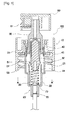
Figure 2 is a cross sectional view illustrating a spray pump according to an embodiment of the present invention. -
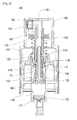
Figure 3 is a cross sectional view illustrating a state that a spray pump sprays according to an embodiment of the present invention. -
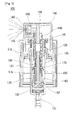
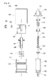
Figure 4 is a cross sectional view illustrating a state that a spry pump is disassembled and assembled according to an embodiment of the present invention. - The spray pump according to an embodiment of the present invention will be described with reference to the accompanying drawings. The same elements or parts shown in the drawings are given the same reference numerals. The detailed descriptions on the known function or construction will be omitted in the middle of the descriptions.
- As shown in
Figure 2 , the spray pump according to the present invention comprises an undercap 110, an overcap 120, acylinder housing 130, astem 140, amain spring 145, apiston rod 150, afirst seal cap 160, asecond seal cap 170, aninner spring 175, a firstleakage discharge hole 135, a secondleakage discharge hole 136 and aspray button 190. - First of all, the under
cap 110 will be described. As shown inFigure 2 , in the center of theunder cap 110 is formed a throughhole 111. Theunder cap 110 is engaged to the top of a container which stores liquid contents. In this case, as shown inFigure 2 , it is preferred that agasket 112 is further installed so as to increase a sealing performance between the undercap 110 and the container. - Next, the over
cap 120 will be described. As shown inFigures 2 and4 , theover cap 120 is engaged to athrough hole 111 of the undercap 110. At an inner side of the over cap is formed astem installation hole 121. As shown inFigures 2 and4 , a suction through hole is formed at a lower side of the overcap 120. To the bottom of the overcap 120 is engaged thecylinder housing 130 which is installed as acheck valve 132 allowing fluid to flow only in a suction direction is mounted at the bottom of the upper, inner side of the suction through hole which is formed at the lower side. - As shown in
Figures 2 and4 , thestem 140 passes through astem installation hole 121 of the overcap 120. The top and bottom of the stem pass through. A springengaging shoulder 141 is formed along an upper, outer circumferential surface of the stem. As shown inFigures 2 and3 , amain spring 145 is installed between the overcap 120 and an outer circumferential surface of thestem 140, so thestem 140 is operable with elastic force with respect to the overcap 120. As a result, any contacts between the liquid contents and themain spring 145 are not allowed, so it is possible to prevent corrosions or damages of themain spring 145 the problems of which used to happen as it comes into direct contact with the liquid contents. In this case, themain spring 145 can be installed between the overcap 120 and thestem 140 in various forms. As one example, as shown inFigures 2 and3 , it is preferred that a springengaging shoulder 141 is further formed along an upper, outer circumferential surface in thestem 140, and themain spring 145 is installed between the upper surface of the cylinder overcap 120 and the springengaging shoulder 141. - As shown in
Figures 2 and4 , at the bottom of thestem 140 is formed afluid passage hole 151 whose too is open and whose bottom is closed in the central axis. Thepiston rod 150 with at least two side passages is inserted into the side surface of the bottom of thefluid passage hole 151. As shown inFigures 2 and4 , at the bottom of thepiston rod 150 is installed afirst seal cap 160 which closes theside passage hole 152 at the descending point and opens theside passage hole 152 at the ascending point and which is movable upward and downward. The outer circumferential surface of thefirst seal cap 160 comes into close contact with the inner surface of thecylinder housing 130. - Meanwhile, as shown in
Figures 2 to 4 , at the top of thefirst seal cap 160 is installed asecond seal cap 170 which is engaged to thepiston rod 150 and whose outer circumferential surface comes into close contact with the inner surface of thecylinder housing 130. As shown inFigures 2 and4 , between thesecond seal cap 170 and thefirst seal cap 160 is installed aninner spring 175, so theside passage hoe 152 can be opened or closed as thefirst seal cap 160 ascends or descends by a difference in the operations which is caused by the elastic force of theinner spring 175 and the viscosity of the liquid contents. - As shown in
Figures 2 and4 , at a side surface wall of thecylinder housing 130 is formed a firstleakage discharge hole 135 whose position corresponds to the top of the Top Dead Point and whose position corresponds to the bottom of the Bottom Dead Point, and a secondleakage discharge hole 136 whose position corresponds to the bottom of the Top Dead Point of thesecond seal cap 170 is formed. If a leakage occurs through a space between thefirst seal cap 160 and thesecond seal cap 170, thesecond seal cap 170 descends, and leakage occurs through the secondleakage discharge hole 136 and the firstleakage discharge hole 135. Since leakage occurs over thesecond seal cap 170 only when the liquid contents all pass through the small gaps between thefirst seal cap 160, thesecond seal cap 170 and the side surface wall of thecylinder housing 130, there is barely a possibility of leakage. When leakage occurs even under the above mentioned situation, as shown inFigure 3 , thesecond seal cap 170 ascends, and the leaked content is discharged through the secondleakage discharge hole 136. Therefore, the present invention makes it possible to prevent the gathering of leaked contents at the portions except for the passages through which liquid contents pass. - In the conventional construction, the spring is installed in the space full of liquid contents all the time. The present invention however has features in that the
inner spring 175 is positioned in a space between thefirst seal cap 160 and thesecond seal cap 170. The space formed between thefirst seal cap 160 and thesecond seal cap 170 may be filled with a small amount of liquid contents only when leakage occurs and may serve to efficiently discharge the leaked liquid contents immediately, so theinner spring 175 does not come into contact with the liquid contents as compared to the conventional invention, whereby damages such as corrosion don't occur in the present invention. - Next, as shown in
Figures 2 to 4 , to the top of thestem 140 is engaged aspray button 190 equipped with aspray passage 191 communicating in a lateral direction, and to the discharge port of thespray passage 191 is engaged aspray nozzle member 192. In this case, thespray nozzle member 192 is made from a transparent or semitransparent material. It is preferred that thespray nozzle member 192 whose colors change based on the spray angle of thespray nozzle member 192 is inserted between thespray passage 191 and thespry nozzle member 192, so the spray angles can be easily checked with bare eyes based on the differences in colors. - Meanwhile, as shown in
Figures 2 and4 , when finishing a protection of the operation portions and an exterior, there is further provided anouter cover 195 at the top of which is formed an opening through which thespray button 190 passes and which is engaged to the undercap 110. - The operations of the spray pump according to an embodiment of the present invention will be described.
- In a standby state as shown in
Figure 2 , the liquid contents which are sucked via thecheck valve 132 are stored at the bottom of thefirst seal cap 160. In this case, thefirst seal cap 160 remains descended with respect to thepiston rod 150 by means of theinner spring 175 and is closing theside passage hole 152. - As shown in
Figure 3 , when a user presses thespray button 190, thepiston rod 150 descends. In this case, thefirst seal cap 160 ascends a little with respect to thepiston rod 150 by means of the pressure from the liquid contents gathered at the bottom of thefirst seal cap 160, so theside passage hole 152 is opened. Therefore, the liquid contents pass through theside passage hole 152, thefluid passage hole 151 and thespray passage 191 and are sprayed through thespray nozzle member 192. - Next, when the user releases the pressed
spray button 190, thepiston rod 150 ascends by themain spring 145. At this time, thefirst seal cap 160 keeps the descended state with respect to thepiston rod 150 with the aid of theinner spring 175, and theside passage hole 152 is closed. The pressure of the lower side of thefirst seal cap 160 of thecylinder housing 130 is lowered by means of the ascending operation with respect to thecylinder housing 130 of thefirst seal cap 160, and the liquid contents are sucked in via theheck valve 132, and the sucked contents gather at the lower side of thefirst seal cap 160 of thecylinder housing 130 for thereby finishing one cycle. - As the present invention may be embodied in several forms without departing from the spirit or essential characteristics thereof, it should also be understood that the above-described examples are not limited by any of the details of the foregoing description, unless otherwise specified, but rather should be construed broadly within its spirit and scope as defined in the appended claims, and therefore all changes and modifications that fall within the meets and bounds of the claims, or equivalences of such meets and bounds are therefore intended to be embraced by the appended claims.
Claims (3)
- A spray pump which sprays liquid contents, comprising:an under cap (110) which has a through hole 111 at its center;an over cap (120) which is engaged to the through hole 111 of the under cap 110 and has a stem installation hole (121) at its inner side;a cylinder housing (130) which is engaged to the bottom of the over cap (120) and has a suction through hole at its lower side and a check valve (132) installed at an inner, lower side of the top of the suction through hole for thereby allowing fluids to flow only in a suction direction;a stem (140) which passes through the stem installation hole 121 of the over cap (120), the center of the stem being passed through from its top to bottom;a main spring 145 which is installed between the over cap (120) and an outer circumferential surface of the stem (140);a piston rod (150) which is inserted into the bottom of the stem (140) and has, on its central axis, a fluid passage hole (151) whose top is open and whose bottom is closed, at least two side passage holes 152 being formed at the lower side surface of the fluid passage hole (151);a first seal cap (160) which is installed movable in upward and downward directions at the bottom of the piston rod 150 and closes the side passage hole (152) at a descending point and opens the side passage hole (152) at an ascending point, an outer circumferential surface of the first seal cap (160) coming into close contact with an inner surface of the cylinder housing (130);a second seal cap (170) which is engaged to the piston rod (150) at the top of the first seal cap (160), an outer circumferential surface of the second seal cap (170) coming into close contact with an inner surface of the cylinder housing (130);an inner spring (175) which is installed between the second seal cap (170) and the first seal cap (160);a first leakage discharge hole (135) which is formed at a side surface wall of the cylinder housing (130) and is positioned at the top of the Top Dead Point of the first seal cap (160) and the bottom of the Bottom Dead Point;a second leakage discharge hole 136 which is formed at a side surface wall of the cylinder housing (130) and is positioned at the bottom of the Top Dead Point of the second seal cap (170);a spray button (190) which is engaged to the top of the stem (140) and has a spray passage (191) communicating in a lateral direction; anda spray nozzle member (192) which is engaged to a discharge port of the spray passage.
- The pump of claim 1, wherein the stem (140) has a spring engaging shoulder (141) formed along an outer circumferential surface of the top, and main spring (145) is installed between the upper surface of the over cap (120) and the spring engaging shoulder (141), and an outer cover (195) has an opening (196) formed at its top through which opening passes the spray button (190) and is engaged to the under cap (110).
- The pump of either claim 1 or claim 2, wherein the spray nozzle member (192) is made from a transparent material or a semitransparent material, and a spray nozzle connection member (193) whose colors change based on the spray angles of the spray nozzle member (192) is inserted between the spray passage (191) and the spray nozzle member (192).
Applications Claiming Priority (2)
| Application Number | Priority Date | Filing Date | Title |
|---|---|---|---|
| KR20110094778A KR101233080B1 (en) | 2011-09-20 | 2011-09-20 | Spray pump |
| PCT/KR2012/007529 WO2013042951A2 (en) | 2011-09-20 | 2012-09-20 | Spray pump |
Publications (3)
| Publication Number | Publication Date |
|---|---|
| EP2759490A2 true EP2759490A2 (en) | 2014-07-30 |
| EP2759490A4 EP2759490A4 (en) | 2015-06-03 |
| EP2759490B1 EP2759490B1 (en) | 2016-08-10 |
Family
ID=47899514
Family Applications (1)
| Application Number | Title | Priority Date | Filing Date |
|---|---|---|---|
| EP12833682.3A Not-in-force EP2759490B1 (en) | 2011-09-20 | 2012-09-20 | Spray pump |
Country Status (7)
| Country | Link |
|---|---|
| US (1) | US9566596B2 (en) |
| EP (1) | EP2759490B1 (en) |
| JP (1) | JP6108181B2 (en) |
| KR (1) | KR101233080B1 (en) |
| CN (1) | CN103796934B (en) |
| ES (1) | ES2599836T3 (en) |
| WO (1) | WO2013042951A2 (en) |
Cited By (4)
| Publication number | Priority date | Publication date | Assignee | Title |
|---|---|---|---|---|
| EP2995385A1 (en) * | 2014-09-10 | 2016-03-16 | Albea do Brasil Embalagens Ltda. | System for dispensing under pressure a product |
| WO2016062541A1 (en) * | 2014-10-21 | 2016-04-28 | F. Holzer Gmbh | Pump head for a metering device, metering device, and applications |
| EP3210671A4 (en) * | 2014-10-22 | 2018-05-30 | Yonwoo Co., Ltd. | Spray orifice structure |
| WO2020144369A1 (en) * | 2019-01-10 | 2020-07-16 | Rieke Packaging Systems Limited | Vented small dose pump dispenser |
Families Citing this family (47)
| Publication number | Priority date | Publication date | Assignee | Title |
|---|---|---|---|---|
| WO2014151208A2 (en) * | 2013-03-15 | 2014-09-25 | Mwv Slatersville, Llc | Vented closure assembly for a spray container |
| KR200475205Y1 (en) * | 2013-12-03 | 2014-11-14 | (주)아모레퍼시픽 | A pump having a articulated stem structure |
| CN103706500A (en) * | 2013-12-13 | 2014-04-09 | 中山市美捷时包装制品有限公司 | Atomizing pump device |
| DE202014103981U1 (en) * | 2014-08-26 | 2015-11-30 | Rpc Bramlage Gmbh | Finger spray pump |
| EP3204112A1 (en) | 2014-10-07 | 2017-08-16 | Boston Scientific Neuromodulation Corporation | Systems, devices, and methods for electrical stimulation using feedback to adjust stimulation parameters |
| FR3028571B1 (en) * | 2014-11-14 | 2019-09-13 | Aptar France Sas | MANUAL PUMP |
| USD830827S1 (en) | 2015-09-21 | 2018-10-16 | S. C. Johnson & Son, Inc. | Container with base |
| USD858288S1 (en) | 2015-09-21 | 2019-09-03 | S. C. Johnson & Son, Inc. | Container with base |
| USD821203S1 (en) | 2015-09-21 | 2018-06-26 | S. C. Johnson & Son, Inc. | Container with cap and base |
| USD821201S1 (en) | 2015-09-21 | 2018-06-26 | S. C. Johnson & Son, Inc. | Container with base |
| USD821202S1 (en) | 2015-09-21 | 2018-06-26 | S. C. Johnson & Son, Inc. | Container with cap and base |
| CN105270760A (en) * | 2015-10-19 | 2016-01-27 | 绍兴市嘉禾塑料制品有限公司 | Spray pump with external springs |
| WO2017111263A1 (en) * | 2015-12-24 | 2017-06-29 | 강성일 | Contents dispensing pump |
| CN105413912A (en) * | 2015-12-25 | 2016-03-23 | 中山市美捷时包装制品有限公司 | A spring external spray pump |
| CN105618297A (en) * | 2015-12-25 | 2016-06-01 | 中山市美捷时包装制品有限公司 | A spring external universal lotion pump |
| CN105413913A (en) * | 2015-12-25 | 2016-03-23 | 中山市美捷时包装制品有限公司 | A spring external universal spray pump |
| US10166563B2 (en) * | 2016-01-08 | 2019-01-01 | Silgan Dispensing Systems Corporation | Pump systems, pump engines, and methods of making the same |
| EP3484628B1 (en) * | 2016-07-18 | 2020-08-26 | RPC Bramlage GmbH | Dispenser of liquid or pasty products |
| JP2018015685A (en) * | 2016-07-25 | 2018-02-01 | 株式会社丸一 | Spring pressure accumulation spray pump |
| DE102016114456A1 (en) * | 2016-08-04 | 2018-02-08 | Rpc Bramlage Gmbh | Fingerspraypumpe and nozzle head for a spray pump |
| DE102016014898A1 (en) * | 2016-12-12 | 2018-06-14 | Aptar Dortmund Gmbh | Pump and dispenser |
| US10107284B2 (en) * | 2016-12-21 | 2018-10-23 | Shanp-Yih Precision Industrial Co., Ltd. | Check valve for pump |
| KR20180002557U (en) * | 2017-02-17 | 2018-08-27 | 주식회사 종우실업 | Hand-operated Spray Pump Comprising Self-sealing Nozzle |
| WO2018187090A1 (en) | 2017-04-03 | 2018-10-11 | Boston Scientific Neuromodulation Corporation | Systems and methods for estimating a volume of activation using a compressed database of threshold values |
| BR112020012804A2 (en) * | 2017-12-27 | 2020-11-24 | Saint-Gobain Performance Plastics Corporation | cover assembly |
| KR102077606B1 (en) * | 2018-03-15 | 2020-02-17 | (주)연우 | orifice and spray vessel having the same |
| KR20200013904A (en) * | 2018-07-31 | 2020-02-10 | 신은주 | Hand pump spring for plastic container and hand pump for plastic container having the spring |
| KR101951627B1 (en) * | 2018-09-20 | 2019-02-25 | (주)삼화피앤티 | Spray pump |
| KR101963619B1 (en) | 2018-09-20 | 2019-03-29 | (주)삼화피앤티 | Spray pump |
| CN109351443B (en) * | 2018-12-02 | 2024-02-27 | 北京协同创新食品科技有限公司 | High-pressure jet nozzle and high-pressure jet crushing device using same |
| KR102216090B1 (en) * | 2019-04-02 | 2021-02-17 | 김성용 | Cosmetic vessel |
| EP3953051B1 (en) * | 2019-04-10 | 2025-04-23 | Lindal France SAS | Two-piece nozzle for aerosol dispensers |
| JP7503979B2 (en) * | 2020-09-11 | 2024-06-21 | 花王株式会社 | Pump dispenser and discharge container |
| WO2022232036A1 (en) | 2021-04-27 | 2022-11-03 | Boston Scientific Neuromodulation Corporation | Systems and methods for automated programming of electrical stimulation |
| EP4313269B1 (en) | 2021-06-15 | 2026-04-15 | Boston Scientific Neuromodulation Corporation | Methods and systems for estimating neural activation by stimulation using a stimulation system |
| KR102496965B1 (en) * | 2021-07-21 | 2023-02-07 | (주)연우 | Pump assembly |
| WO2023003387A1 (en) * | 2021-07-21 | 2023-01-26 | 주식회사 연우 | Pump assembly |
| WO2023107457A2 (en) | 2021-12-09 | 2023-06-15 | Boston Scientific Neuromodulation Corparation | Methods and systems for monitoring or assessing movement disorders or other physiological parameters using a stimulation system |
| WO2023107449A2 (en) | 2021-12-10 | 2023-06-15 | Boston Scientific Neuromodulation Corporation | Systems and methods for generating and using response maps for electrical stimulation |
| EP4415807A1 (en) | 2021-12-10 | 2024-08-21 | Boston Scientific Neuromodulation Corporation | Methods and systems for determining and using an intensity index for electrical stimulation |
| WO2023167872A1 (en) | 2022-03-02 | 2023-09-07 | Boston Scientific Neuromodulation Corporation | Systems and methods for monitoring stimulation drift in an electrical stimulation system |
| KR102768394B1 (en) * | 2022-07-22 | 2025-02-19 | 강성일 | Content exhaust pump |
| KR102679452B1 (en) * | 2022-09-08 | 2024-06-27 | 강민구 | Waterproof structure of pump dispenser for container |
| JP7844318B2 (en) * | 2022-11-30 | 2026-04-13 | 株式会社吉野工業所 | Dispenser |
| CN116588500B (en) | 2023-06-08 | 2025-10-28 | 浙江锦盛新材料股份有限公司 | A compression pump |
| CN117000079B (en) * | 2023-08-15 | 2026-03-20 | 浙江罗星化学股份有限公司 | A mixing device and its usage method for producing solvent-free polyurethane treatment agents. |
| KR102887018B1 (en) * | 2024-02-02 | 2025-11-14 | 강성일 | Content exhaust pump container |
Family Cites Families (27)
| Publication number | Priority date | Publication date | Assignee | Title |
|---|---|---|---|---|
| JPS5824183B2 (en) * | 1974-05-17 | 1983-05-19 | コンドウ ヒロシ | Chikuatsufunmusouchi |
| US4340158A (en) * | 1980-06-13 | 1982-07-20 | Realex Corporation | Vent-sealing, down-locked pump dispenser |
| US4325501A (en) * | 1980-10-31 | 1982-04-20 | Ethyl Products Company | Extended spray pump |
| US5025956A (en) * | 1988-10-11 | 1991-06-25 | Linsenbigler James G | Safety top sprayer |
| FR2726045B1 (en) * | 1994-10-19 | 1997-01-10 | Sofab | MINIATURE PREPRESSURE PUMP |
| DE19605153A1 (en) * | 1996-02-13 | 1997-08-14 | Pfeiffer Erich Gmbh & Co Kg | Discharge device for media and method for producing a discharge device or the like. |
| US6158617A (en) | 1996-10-30 | 2000-12-12 | The Procter & Gamble Company | Concentrated reduced dosage spray pump delivery system |
| US6375045B1 (en) * | 2000-03-30 | 2002-04-23 | Yonwoo Corporation | Airless type dispenser |
| JP2002066401A (en) * | 2000-06-16 | 2002-03-05 | Katsutoshi Masuda | Fluid delivery pump |
| KR100485039B1 (en) | 2002-04-12 | 2005-04-27 | 펌텍코리아 (주) | Spray pump of cosmetic case |
| KR200288637Y1 (en) * | 2002-06-07 | 2002-09-11 | 임준국 | Mixture type case |
| US6685062B1 (en) * | 2002-09-16 | 2004-02-03 | Yon Woo Corporation | Dispenser pump |
| KR100527679B1 (en) * | 2002-12-14 | 2005-11-15 | 주식회사 종우실업 | Manually-operated and small-sized spray pump with ability of soft pumping |
| FR2849000B1 (en) * | 2002-12-23 | 2005-07-08 | Valois Sas | DEVICE FOR DISPENSING FLUID PRODUCT. |
| DE10334032B4 (en) * | 2003-07-18 | 2005-06-23 | Ing. Erich Pfeiffer Gmbh | valve means |
| FR2865198B1 (en) * | 2004-01-16 | 2006-04-14 | Valois Sas | DEVICE FOR DISPENSING FLUID PRODUCT |
| KR200428274Y1 (en) * | 2006-07-19 | 2006-10-12 | (주)연우 | Dispenser container |
| FR2910449B1 (en) * | 2006-12-22 | 2009-03-06 | Rexam Dispensing Systems Sas | COMPACT PUMP HAVING CAPACITY FOR ROTULATING THE SPRAY WITH RESPECT TO THE PISTON. |
| KR200436957Y1 (en) | 2007-01-05 | 2007-10-19 | (주)연우 | Dispenser for resuction of discharged contents |
| KR100814319B1 (en) * | 2007-08-27 | 2008-03-18 | (주)연우 | Nozzle Retractable Dispenser |
| KR100819764B1 (en) | 2007-10-22 | 2008-04-08 | (주)연우 | Dispenser container |
| KR200440665Y1 (en) * | 2008-03-25 | 2008-06-24 | (주)연우 | Pumped Cosmetic Container |
| US20100135834A1 (en) * | 2008-12-03 | 2010-06-03 | Living Fountain Plastic Industrial Co., Ltd. | Double-piston mechanism of an emulsion squeeze head |
| KR200459637Y1 (en) * | 2009-12-31 | 2012-04-12 | 강성일 | Contents exhaust pump |
| US20130026186A1 (en) * | 2009-04-17 | 2013-01-31 | Walter Jenkins | Child-Resistant Fluid Dispersion Device |
| ITMI20091648A1 (en) * | 2009-09-25 | 2011-03-26 | Modapack S R L | "GROUP FOR THE PRESSURIZATION AND DISTRIBUTION OF FLUID SUBSTANCES FOR A MANUAL-OPERATED PUMP AND PUMP INCLUDING THE GROUP" |
| CN102770666B (en) * | 2010-01-28 | 2015-11-25 | 株式会社吉野工业所 | Pump |
-
2011
- 2011-09-20 KR KR20110094778A patent/KR101233080B1/en not_active Expired - Fee Related
-
2012
- 2012-09-20 EP EP12833682.3A patent/EP2759490B1/en not_active Not-in-force
- 2012-09-20 CN CN201280044139.5A patent/CN103796934B/en not_active Expired - Fee Related
- 2012-09-20 WO PCT/KR2012/007529 patent/WO2013042951A2/en not_active Ceased
- 2012-09-20 US US14/342,645 patent/US9566596B2/en not_active Expired - Fee Related
- 2012-09-20 ES ES12833682.3T patent/ES2599836T3/en active Active
- 2012-09-20 JP JP2014530607A patent/JP6108181B2/en not_active Expired - Fee Related
Cited By (6)
| Publication number | Priority date | Publication date | Assignee | Title |
|---|---|---|---|---|
| EP2995385A1 (en) * | 2014-09-10 | 2016-03-16 | Albea do Brasil Embalagens Ltda. | System for dispensing under pressure a product |
| WO2016062541A1 (en) * | 2014-10-21 | 2016-04-28 | F. Holzer Gmbh | Pump head for a metering device, metering device, and applications |
| RU2694760C2 (en) * | 2014-10-21 | 2019-07-16 | Ф. Хольцер Гмбх | Pump nozzle for dispenser, metering device and possibility of their application |
| US10384221B2 (en) | 2014-10-21 | 2019-08-20 | F. Holzer Gmbh | Pump head for a metering device, metering device and also possibilities for use |
| EP3210671A4 (en) * | 2014-10-22 | 2018-05-30 | Yonwoo Co., Ltd. | Spray orifice structure |
| WO2020144369A1 (en) * | 2019-01-10 | 2020-07-16 | Rieke Packaging Systems Limited | Vented small dose pump dispenser |
Also Published As
| Publication number | Publication date |
|---|---|
| EP2759490A4 (en) | 2015-06-03 |
| CN103796934A (en) | 2014-05-14 |
| JP2014532013A (en) | 2014-12-04 |
| JP6108181B2 (en) | 2017-04-05 |
| US20140217124A1 (en) | 2014-08-07 |
| WO2013042951A2 (en) | 2013-03-28 |
| KR101233080B1 (en) | 2013-02-14 |
| EP2759490B1 (en) | 2016-08-10 |
| CN103796934B (en) | 2015-10-07 |
| ES2599836T3 (en) | 2017-02-03 |
| WO2013042951A3 (en) | 2013-05-23 |
| US9566596B2 (en) | 2017-02-14 |
Similar Documents
| Publication | Publication Date | Title |
|---|---|---|
| EP2759490B1 (en) | Spray pump | |
| US9144813B2 (en) | Pump-type cosmetics container | |
| US4050613A (en) | Manual actuated dispensing pump | |
| JP2622795B2 (en) | Liquid pump distributor | |
| EP2737823A2 (en) | Pump-type cosmetics container | |
| EP1565270B1 (en) | Reduced-height precompression pump | |
| RU2011122957A (en) | DISPENSING CONTAINER | |
| WO2021149871A1 (en) | Pump container | |
| EP0145155B1 (en) | Dispenser for a flowable product | |
| US7108160B2 (en) | Manually operable pump for dispensing creamy substances | |
| EP1938903A3 (en) | Pump Dispenser | |
| US5738252A (en) | Upright/inverted sprayer | |
| KR20160033687A (en) | High pressure pump | |
| USRE33235E (en) | Liquid dispensing pump | |
| KR102659177B1 (en) | Dispensing member and distributor comprising the member | |
| US9296003B2 (en) | Dispensing pump | |
| KR101036269B1 (en) | Airless type cosmetic container with side discharge passage | |
| KR100485039B1 (en) | Spray pump of cosmetic case | |
| AU724771B2 (en) | Upright/inverted sprayer | |
| KR200281927Y1 (en) | Spray pump of cosmetic case | |
| US4063854A (en) | Spray pump assembly | |
| KR20180002557U (en) | Hand-operated Spray Pump Comprising Self-sealing Nozzle | |
| KR20240013631A (en) | Content exhaust pump | |
| RU2007115536A (en) | PUMP FOR DISTRIBUTION OF LIQUID SUBSTANCE WITHOUT ACCESS OF AIR AND APPROPRIATE DISPENSER | |
| TH11029B (en) | Liquid dosing pump with water barrier |
Legal Events
| Date | Code | Title | Description |
|---|---|---|---|
| PUAI | Public reference made under article 153(3) epc to a published international application that has entered the european phase |
Free format text: ORIGINAL CODE: 0009012 |
|
| 17P | Request for examination filed |
Effective date: 20140211 |
|
| AK | Designated contracting states |
Kind code of ref document: A2 Designated state(s): AL AT BE BG CH CY CZ DE DK EE ES FI FR GB GR HR HU IE IS IT LI LT LU LV MC MK MT NL NO PL PT RO RS SE SI SK SM TR |
|
| DAX | Request for extension of the european patent (deleted) | ||
| A4 | Supplementary search report drawn up and despatched |
Effective date: 20150508 |
|
| RIC1 | Information provided on ipc code assigned before grant |
Ipc: B05B 11/00 20060101ALI20150430BHEP Ipc: B65D 83/76 20060101AFI20150430BHEP Ipc: B05B 7/02 20060101ALI20150430BHEP |
|
| GRAP | Despatch of communication of intention to grant a patent |
Free format text: ORIGINAL CODE: EPIDOSNIGR1 |
|
| INTG | Intention to grant announced |
Effective date: 20160224 |
|
| GRAS | Grant fee paid |
Free format text: ORIGINAL CODE: EPIDOSNIGR3 |
|
| GRAA | (expected) grant |
Free format text: ORIGINAL CODE: 0009210 |
|
| AK | Designated contracting states |
Kind code of ref document: B1 Designated state(s): AL AT BE BG CH CY CZ DE DK EE ES FI FR GB GR HR HU IE IS IT LI LT LU LV MC MK MT NL NO PL PT RO RS SE SI SK SM TR |
|
| REG | Reference to a national code |
Ref country code: GB Ref legal event code: FG4D |
|
| REG | Reference to a national code |
Ref country code: CH Ref legal event code: EP Ref country code: AT Ref legal event code: REF Ref document number: 818772 Country of ref document: AT Kind code of ref document: T Effective date: 20160815 |
|
| REG | Reference to a national code |
Ref country code: IE Ref legal event code: FG4D |
|
| REG | Reference to a national code |
Ref country code: DE Ref legal event code: R096 Ref document number: 602012021657 Country of ref document: DE |
|
| REG | Reference to a national code |
Ref country code: FR Ref legal event code: PLFP Year of fee payment: 5 |
|
| REG | Reference to a national code |
Ref country code: LT Ref legal event code: MG4D |
|
| REG | Reference to a national code |
Ref country code: NL Ref legal event code: MP Effective date: 20160810 |
|
| REG | Reference to a national code |
Ref country code: AT Ref legal event code: MK05 Ref document number: 818772 Country of ref document: AT Kind code of ref document: T Effective date: 20160810 |
|
| PG25 | Lapsed in a contracting state [announced via postgrant information from national office to epo] |
Ref country code: RS Free format text: LAPSE BECAUSE OF FAILURE TO SUBMIT A TRANSLATION OF THE DESCRIPTION OR TO PAY THE FEE WITHIN THE PRESCRIBED TIME-LIMIT Effective date: 20160810 Ref country code: HR Free format text: LAPSE BECAUSE OF FAILURE TO SUBMIT A TRANSLATION OF THE DESCRIPTION OR TO PAY THE FEE WITHIN THE PRESCRIBED TIME-LIMIT Effective date: 20160810 Ref country code: NO Free format text: LAPSE BECAUSE OF FAILURE TO SUBMIT A TRANSLATION OF THE DESCRIPTION OR TO PAY THE FEE WITHIN THE PRESCRIBED TIME-LIMIT Effective date: 20161110 Ref country code: IT Free format text: LAPSE BECAUSE OF FAILURE TO SUBMIT A TRANSLATION OF THE DESCRIPTION OR TO PAY THE FEE WITHIN THE PRESCRIBED TIME-LIMIT Effective date: 20160810 Ref country code: FI Free format text: LAPSE BECAUSE OF FAILURE TO SUBMIT A TRANSLATION OF THE DESCRIPTION OR TO PAY THE FEE WITHIN THE PRESCRIBED TIME-LIMIT Effective date: 20160810 Ref country code: LT Free format text: LAPSE BECAUSE OF FAILURE TO SUBMIT A TRANSLATION OF THE DESCRIPTION OR TO PAY THE FEE WITHIN THE PRESCRIBED TIME-LIMIT Effective date: 20160810 Ref country code: NL Free format text: LAPSE BECAUSE OF FAILURE TO SUBMIT A TRANSLATION OF THE DESCRIPTION OR TO PAY THE FEE WITHIN THE PRESCRIBED TIME-LIMIT Effective date: 20160810 Ref country code: IS Free format text: LAPSE BECAUSE OF FAILURE TO SUBMIT A TRANSLATION OF THE DESCRIPTION OR TO PAY THE FEE WITHIN THE PRESCRIBED TIME-LIMIT Effective date: 20161210 |
|
| REG | Reference to a national code |
Ref country code: ES Ref legal event code: FG2A Ref document number: 2599836 Country of ref document: ES Kind code of ref document: T3 Effective date: 20170203 |
|
| PG25 | Lapsed in a contracting state [announced via postgrant information from national office to epo] |
Ref country code: PL Free format text: LAPSE BECAUSE OF FAILURE TO SUBMIT A TRANSLATION OF THE DESCRIPTION OR TO PAY THE FEE WITHIN THE PRESCRIBED TIME-LIMIT Effective date: 20160810 Ref country code: LV Free format text: LAPSE BECAUSE OF FAILURE TO SUBMIT A TRANSLATION OF THE DESCRIPTION OR TO PAY THE FEE WITHIN THE PRESCRIBED TIME-LIMIT Effective date: 20160810 Ref country code: SE Free format text: LAPSE BECAUSE OF FAILURE TO SUBMIT A TRANSLATION OF THE DESCRIPTION OR TO PAY THE FEE WITHIN THE PRESCRIBED TIME-LIMIT Effective date: 20160810 Ref country code: GR Free format text: LAPSE BECAUSE OF FAILURE TO SUBMIT A TRANSLATION OF THE DESCRIPTION OR TO PAY THE FEE WITHIN THE PRESCRIBED TIME-LIMIT Effective date: 20161111 Ref country code: AT Free format text: LAPSE BECAUSE OF FAILURE TO SUBMIT A TRANSLATION OF THE DESCRIPTION OR TO PAY THE FEE WITHIN THE PRESCRIBED TIME-LIMIT Effective date: 20160810 Ref country code: PT Free format text: LAPSE BECAUSE OF FAILURE TO SUBMIT A TRANSLATION OF THE DESCRIPTION OR TO PAY THE FEE WITHIN THE PRESCRIBED TIME-LIMIT Effective date: 20161212 Ref country code: BE Free format text: LAPSE BECAUSE OF NON-PAYMENT OF DUE FEES Effective date: 20160930 |
|
| PG25 | Lapsed in a contracting state [announced via postgrant information from national office to epo] |
Ref country code: EE Free format text: LAPSE BECAUSE OF FAILURE TO SUBMIT A TRANSLATION OF THE DESCRIPTION OR TO PAY THE FEE WITHIN THE PRESCRIBED TIME-LIMIT Effective date: 20160810 Ref country code: RO Free format text: LAPSE BECAUSE OF FAILURE TO SUBMIT A TRANSLATION OF THE DESCRIPTION OR TO PAY THE FEE WITHIN THE PRESCRIBED TIME-LIMIT Effective date: 20160810 |
|
| REG | Reference to a national code |
Ref country code: CH Ref legal event code: PL |
|
| REG | Reference to a national code |
Ref country code: DE Ref legal event code: R097 Ref document number: 602012021657 Country of ref document: DE |
|
| PG25 | Lapsed in a contracting state [announced via postgrant information from national office to epo] |
Ref country code: DK Free format text: LAPSE BECAUSE OF FAILURE TO SUBMIT A TRANSLATION OF THE DESCRIPTION OR TO PAY THE FEE WITHIN THE PRESCRIBED TIME-LIMIT Effective date: 20160810 Ref country code: SM Free format text: LAPSE BECAUSE OF FAILURE TO SUBMIT A TRANSLATION OF THE DESCRIPTION OR TO PAY THE FEE WITHIN THE PRESCRIBED TIME-LIMIT Effective date: 20160810 Ref country code: BG Free format text: LAPSE BECAUSE OF FAILURE TO SUBMIT A TRANSLATION OF THE DESCRIPTION OR TO PAY THE FEE WITHIN THE PRESCRIBED TIME-LIMIT Effective date: 20161110 Ref country code: BE Free format text: LAPSE BECAUSE OF FAILURE TO SUBMIT A TRANSLATION OF THE DESCRIPTION OR TO PAY THE FEE WITHIN THE PRESCRIBED TIME-LIMIT Effective date: 20160810 Ref country code: SK Free format text: LAPSE BECAUSE OF FAILURE TO SUBMIT A TRANSLATION OF THE DESCRIPTION OR TO PAY THE FEE WITHIN THE PRESCRIBED TIME-LIMIT Effective date: 20160810 Ref country code: CZ Free format text: LAPSE BECAUSE OF FAILURE TO SUBMIT A TRANSLATION OF THE DESCRIPTION OR TO PAY THE FEE WITHIN THE PRESCRIBED TIME-LIMIT Effective date: 20160810 |
|
| PLBE | No opposition filed within time limit |
Free format text: ORIGINAL CODE: 0009261 |
|
| STAA | Information on the status of an ep patent application or granted ep patent |
Free format text: STATUS: NO OPPOSITION FILED WITHIN TIME LIMIT |
|
| REG | Reference to a national code |
Ref country code: IE Ref legal event code: MM4A |
|
| PG25 | Lapsed in a contracting state [announced via postgrant information from national office to epo] |
Ref country code: MC Free format text: LAPSE BECAUSE OF FAILURE TO SUBMIT A TRANSLATION OF THE DESCRIPTION OR TO PAY THE FEE WITHIN THE PRESCRIBED TIME-LIMIT Effective date: 20160810 |
|
| 26N | No opposition filed |
Effective date: 20170511 |
|
| PG25 | Lapsed in a contracting state [announced via postgrant information from national office to epo] |
Ref country code: CH Free format text: LAPSE BECAUSE OF NON-PAYMENT OF DUE FEES Effective date: 20160930 Ref country code: IE Free format text: LAPSE BECAUSE OF NON-PAYMENT OF DUE FEES Effective date: 20160920 Ref country code: LI Free format text: LAPSE BECAUSE OF NON-PAYMENT OF DUE FEES Effective date: 20160930 |
|
| PG25 | Lapsed in a contracting state [announced via postgrant information from national office to epo] |
Ref country code: SI Free format text: LAPSE BECAUSE OF FAILURE TO SUBMIT A TRANSLATION OF THE DESCRIPTION OR TO PAY THE FEE WITHIN THE PRESCRIBED TIME-LIMIT Effective date: 20160810 Ref country code: LU Free format text: LAPSE BECAUSE OF NON-PAYMENT OF DUE FEES Effective date: 20160920 |
|
| REG | Reference to a national code |
Ref country code: FR Ref legal event code: PLFP Year of fee payment: 6 |
|
| PGFP | Annual fee paid to national office [announced via postgrant information from national office to epo] |
Ref country code: DE Payment date: 20170902 Year of fee payment: 6 Ref country code: GB Payment date: 20170925 Year of fee payment: 6 Ref country code: FR Payment date: 20170925 Year of fee payment: 6 |
|
| PGFP | Annual fee paid to national office [announced via postgrant information from national office to epo] |
Ref country code: ES Payment date: 20171003 Year of fee payment: 6 |
|
| PG25 | Lapsed in a contracting state [announced via postgrant information from national office to epo] |
Ref country code: HU Free format text: LAPSE BECAUSE OF FAILURE TO SUBMIT A TRANSLATION OF THE DESCRIPTION OR TO PAY THE FEE WITHIN THE PRESCRIBED TIME-LIMIT; INVALID AB INITIO Effective date: 20120920 |
|
| PG25 | Lapsed in a contracting state [announced via postgrant information from national office to epo] |
Ref country code: CY Free format text: LAPSE BECAUSE OF FAILURE TO SUBMIT A TRANSLATION OF THE DESCRIPTION OR TO PAY THE FEE WITHIN THE PRESCRIBED TIME-LIMIT Effective date: 20160810 Ref country code: MK Free format text: LAPSE BECAUSE OF FAILURE TO SUBMIT A TRANSLATION OF THE DESCRIPTION OR TO PAY THE FEE WITHIN THE PRESCRIBED TIME-LIMIT Effective date: 20160810 Ref country code: MT Free format text: LAPSE BECAUSE OF NON-PAYMENT OF DUE FEES Effective date: 20160930 |
|
| PG25 | Lapsed in a contracting state [announced via postgrant information from national office to epo] |
Ref country code: TR Free format text: LAPSE BECAUSE OF FAILURE TO SUBMIT A TRANSLATION OF THE DESCRIPTION OR TO PAY THE FEE WITHIN THE PRESCRIBED TIME-LIMIT Effective date: 20160810 Ref country code: AL Free format text: LAPSE BECAUSE OF FAILURE TO SUBMIT A TRANSLATION OF THE DESCRIPTION OR TO PAY THE FEE WITHIN THE PRESCRIBED TIME-LIMIT Effective date: 20160810 |
|
| REG | Reference to a national code |
Ref country code: DE Ref legal event code: R119 Ref document number: 602012021657 Country of ref document: DE |
|
| GBPC | Gb: european patent ceased through non-payment of renewal fee |
Effective date: 20180920 |
|
| PG25 | Lapsed in a contracting state [announced via postgrant information from national office to epo] |
Ref country code: DE Free format text: LAPSE BECAUSE OF NON-PAYMENT OF DUE FEES Effective date: 20190402 |
|
| PG25 | Lapsed in a contracting state [announced via postgrant information from national office to epo] |
Ref country code: FR Free format text: LAPSE BECAUSE OF NON-PAYMENT OF DUE FEES Effective date: 20180930 |
|
| PG25 | Lapsed in a contracting state [announced via postgrant information from national office to epo] |
Ref country code: GB Free format text: LAPSE BECAUSE OF NON-PAYMENT OF DUE FEES Effective date: 20180920 |
|
| REG | Reference to a national code |
Ref country code: ES Ref legal event code: FD2A Effective date: 20191031 |
|
| PG25 | Lapsed in a contracting state [announced via postgrant information from national office to epo] |
Ref country code: ES Free format text: LAPSE BECAUSE OF NON-PAYMENT OF DUE FEES Effective date: 20180921 |