EP2759486A1 - Closing system for a container - Google Patents
Closing system for a container Download PDFInfo
- Publication number
- EP2759486A1 EP2759486A1 EP13305096.3A EP13305096A EP2759486A1 EP 2759486 A1 EP2759486 A1 EP 2759486A1 EP 13305096 A EP13305096 A EP 13305096A EP 2759486 A1 EP2759486 A1 EP 2759486A1
- Authority
- EP
- European Patent Office
- Prior art keywords
- cover
- closing system
- cap
- vial
- user
- Prior art date
- Legal status (The legal status is an assumption and is not a legal conclusion. Google has not performed a legal analysis and makes no representation as to the accuracy of the status listed.)
- Withdrawn
Links
Images


Classifications
-
- B—PERFORMING OPERATIONS; TRANSPORTING
- B65—CONVEYING; PACKING; STORING; HANDLING THIN OR FILAMENTARY MATERIAL
- B65D—CONTAINERS FOR STORAGE OR TRANSPORT OF ARTICLES OR MATERIALS, e.g. BAGS, BARRELS, BOTTLES, BOXES, CANS, CARTONS, CRATES, DRUMS, JARS, TANKS, HOPPERS, FORWARDING CONTAINERS; ACCESSORIES, CLOSURES, OR FITTINGS THEREFOR; PACKAGING ELEMENTS; PACKAGES
- B65D47/00—Closures with filling and discharging, or with discharging, devices
- B65D47/04—Closures with discharging devices other than pumps
- B65D47/20—Closures with discharging devices other than pumps comprising hand-operated members for controlling discharge
- B65D47/26—Closures with discharging devices other than pumps comprising hand-operated members for controlling discharge with slide valves, i.e. valves that open and close a passageway by sliding over a port, e.g. formed with slidable spouts
- B65D47/261—Closures with discharging devices other than pumps comprising hand-operated members for controlling discharge with slide valves, i.e. valves that open and close a passageway by sliding over a port, e.g. formed with slidable spouts having a rotational or helicoidal movement
- B65D47/265—Closures with discharging devices other than pumps comprising hand-operated members for controlling discharge with slide valves, i.e. valves that open and close a passageway by sliding over a port, e.g. formed with slidable spouts having a rotational or helicoidal movement between planar parts
-
- B—PERFORMING OPERATIONS; TRANSPORTING
- B65—CONVEYING; PACKING; STORING; HANDLING THIN OR FILAMENTARY MATERIAL
- B65D—CONTAINERS FOR STORAGE OR TRANSPORT OF ARTICLES OR MATERIALS, e.g. BAGS, BARRELS, BOTTLES, BOXES, CANS, CARTONS, CRATES, DRUMS, JARS, TANKS, HOPPERS, FORWARDING CONTAINERS; ACCESSORIES, CLOSURES, OR FITTINGS THEREFOR; PACKAGING ELEMENTS; PACKAGES
- B65D51/00—Closures not otherwise provided for
- B65D51/002—Closures to be pierced by an extracting-device for the contents and fixed on the container by separate retaining means
Definitions
- the present invention relates to a closing system for a hand-held medical container, said closing system allowing both opening and closing of said container with a single hand
- Small containers that can be hold with a single hand, such as bottles, vials or tubes are widely use in everyday life to store some material in the form of a liquid, a paste or divided matter. They usually consist in a storage compartment, intended to store the material and a closing system, intended to prevent spilling of the material when the container is transported or turned over.
- the distal end of a component or apparatus must be understood as meaning the end furthest from the hand of the user and the proximal end must be understood as meaning the end closest to the hand of the user, with reference to the injection device intended to be used with said component or apparatus.
- the distal direction must be understood as the direction of injection with reference to the injection device, and the proximal direction is the opposite direction, i.e. the direction of the transfer of the product from the vial to the injection device.
- hand-held containers such as vials are commonly used to store and distribute drugs or vaccines intended to be injected to patients.
- Such containers are inexpensive, durable and can be made sterile before being filled with a pharmaceutical product.
- a number of doses can be stored in a limited space and such medical containers are therefore convenient for medical staff working outside of the hospital. Indeed, they are widely used in large scale immunization programs or during pandemics, where populations living in remote area, far away from towns and hospital facilities, need to be vaccinated or cured.
- vials are usually closed by a septum intended to be pierced by the needle of an injection device.
- This septum therefore acts as a barrier between the inside of the vial and the outside environment: it protects the pharmaceutical product stored in said vial from outside contaminants such as dust, bacteria, germs or viruses.
- the septum itself may be damaged during transportation or when handled in rough conditions. This could include shocks, excessive sunlight, excessive temperature, very low or high humidity level, or contact with hazardous liquid. Additionally, it is sometimes difficult to guaranty favorable hygienic conditions in such remote locations, and the septum and/or the vials could be contacted by unclean hands or contaminated surfaces. Finally, and in the case of multidose vials, the septum needs to be pierced several successive times i.e. as many times as the number of product doses stored into the vial. This repeated piercing could mechanically damage the septum, for example by leaving tiny holes through its material.
- a first embodiment of the present invention is a closing system for a container to be hold with a single hand, said closing system comprising:
- the closing system of the present invention is intended to be adapted to a hand-held container.
- This could be a medical container, such as for example a conventional vial for storing pharmaceutical products, such as multidose vials for vaccines.
- a vial 1 is shown on Figures 1A-1C and generally comprises a tubular barrel 2 having a longitudinal axis A, closed at an end and having a collar 3 at the opposite end, said collar 3 forming an opening 3a closed by a septum 4.
- the septum 4 is fixedly attached to the collar 3 of the vial 1 by a peripheral band 5, said peripheral band 5 leaving a part of the septum 4, herein called outer surface 4a of the septum, directly facing the outside of the vial 1, namely the outside environment.
- the septum 4 is usually made of a material impermeable to gas and liquid and it seals hermetically the content of the vial 1.
- the septum 4 is also pierceable by the needle of an injection device intended to be filled with the product contained in the vial, said septum 4 being accessible to said needle via its outer surface 4a.
- the closing system of the present invention could be integrated in the hand-held container, the cap being a part of the container wall.
- the closing system of the present invention allows an efficient closure of the vial and an efficient protection of the vial septum. Thanks to the hinge and the guiding member, it is also very simple to manipulate with a single hand: the container can be grasped by one hand and only the thumb is required to open and close the cover.
- the closing system is thus particularly valuable in the field of medicine where the health workers often need their second hand to handle a swab, another container or an injection device. Furthermore, the cover cannot be separated from the cap even if the container falls during operation. The closing system is therefore resistant to rough conditions often met in remote areas, outside the hospital.
- the hinge of the closing system comprises a shaft extending in the distal direction from the cover, and a corner hole provided in the transversal wall. This hinge allows a straightforward planar movement of the cover regarding the cap: the cover slides in a planar rotation regarding the transversal wall to give access to the access port. Moreover, the cover can be guided during the whole movement by a single finger contacting the guiding member.
- the guiding member is a stud. This shape has been found preferable to allow the user's thumb to guide the cover during the closing and the opening. Moreover, the stud also provides a visual and tactile indication to the user for an obvious operation of the closing system. Any health care worker is thus able to use the closing system in an appropriate way without a specific training.
- the guiding member could be a hole, a lug or a ring.
- the cover further comprises a pushing surface, to allow the opening of the cover by a suggested thrust movement from the user's thumb. It also provides further visual and tactile indication for an untrained user to operate the closing system in an appropriate way.
- the hinge is located on a side of the cover. This position allows a fast opening with only a limited movement of the user's thumb.
- the hinge is also located on a rear portion of the cover, to allow a natural sliding movement to the back of the closing system.
- the pushing surface is located on a front portion of the cover, in order to be located nearby the user's thumb when the user grasps the container with his hand. Due to its position, the user is lead to push onto this surface without a specific training.
- the stud is located on a rear portion of the cover. This position is advantageous to supplement the pushing surface during the opening movement, in particular in case the user does not grasp the container in the most appropriate way.
- the stud is located on a first side of the cover and the hinge is located on an opposite, second side of the cover. Consequently, the stud located on a rear portion of the cover is brought nearby the user's thumb when the cover is in the open position. The closing movement is thus rendered obvious to untrained users, as they only need to pull the stud with their thumb to close the cover.
- the pushing surface and the stud are located on the same first side of the cover.
- the pushing surface is thus located at another extremity of the cover regarding the hinge, which allows smooth and easy opening of the cover thanks to a leverage effect.
- said thumb would come in contact with the stud and a fast opening will be possible anyway.
- the closing system comprises unidirectional means only allowing a clockwise or a counterclockwise rotation. This forces the user to manipulate the closing system in only one direction, therefore restricting any inappropriate operation.
- the closing and the opening must be done in the same clockwise or counterclockwise movement, which renders the closing system safe and obvious to manipulate.
- said unidirectional means comprises a tooth located on a flexible leg substantially parallel to said cover, and three openings located on said transversal wall.
- the closing system further comprises locking means to maintain the cover in a closed position during storage. These locking means prevent undesired opening of the cover, in particular during storage and shipping.
- the locking means comprises a peg located on a longitudinal extension of said cover, and a notch located on the skirt. Only a small pressure is required to disengage the peg from the notch and these locking means efficiently prevents undesired opening without hampering a simple opening of the closing system.
- said transversal wall comprises a rear extension intended to block the user's index finger when said user grasps said closing system. This helps the user to firmly grasp the container, even if the user's hand or the container is wet or dirty. Moreover, it also helps to correctly place the thumb nearby the pushing surface and thus improves the obviousness to manipulate the closing system.
- the adaptor 10 comprises a gripping member 20 intended to secure the adaptor onto the vial 1, a counting ring 30 intended to provide information on the number of doses of product already withdrawn from the vial 1 and/or still left inside the vial 1, a cap 40, intended to be snap-fitted to the gripping member 20, a pierceable elastomeric piece 50 intended to be accommodated in the cap 40, and a cover 60 intended to prevent or allow access to the opening 3a of the vial 1, once the adaptor 10 is coupled to the vial 1.
- the gripping member 20 comprises a U-shaped body 21, having a partially tubular wall 22 with a height suitable for surrounding the collar 3 of the vial 1 (see Figures 11A-11B ).
- the gripping member further comprises two free ends 22a corresponding to the ends of the branches of the U, the U-shaped body 21 therefore forming a clipping member.
- the tubular wall 22 is provided on its outer surface with radial pegs 23 (only one being visible on Figure 2 ).
- Each free end 22a is further provided with a distal front projection forming a radial rim 24.
- the counting ring 30 is made of a flat cylinder 31 provided with a plurality of outer radial teeth 32 distributed along its periphery 31a.
- the flat cylinder 31 is further provided with a central hole 33 dimensioned and shaped so as to fit around radial outer pegs 47of the cap 40, as shown on Figures 4-6 .
- the adaptor 10 is intended to be coupled to a multidose vial 1 filled with ten doses of product.
- the counting ring 30 is provided with information data corresponding to these ten doses of product to be withdrawn from the vial 1.
- the flat cylinder 31 is thus provided with printed digits 34 indicating the numbers 1 to 10, these digits being regularly distributed along the circumference of the flat cylinder 31.
- the cap 40 comprises a transversal wall 41 having a substantially circular shape except a corner 41a, and a rear extension 41b.
- a front rim 42 is extending from the front of the transversal wall 41 in the distal direction.
- a U-shaped skirt 43 also extends from the transversal wall 41 in the distal direction, the free ends 43a of the U forming a front opening 43b of the skirt 43. Close to each free end 43a, the skirt 43 is provided on its outer surface with four recesses 43c (only two being visible on Figure 2 ) and a notch 43d immediately nearby the transversal wall 41.
- the circular transversal wall 41 is provided with a central access port 44 and with a front side hole 45.
- the transversal wall 41 is further provided in its corner 41a with a corner hole 46 surrounded by three openings 49a, 49b and 49c regularly placed around the corner hole.
- the access port 44 is designed to accommodate a needle and is described as a needle access port 44.
- the proximal face of the transversal wall 41 is provided with three radial outer pegs 47 and the U-shaped skirt 43 is provided on its inner wall with a corner transversal rim 48having a central hole 48a that faces the corner hole 46.
- the cap 40 is sized and shape for receiving the counting ring 30 and the gripping member 20.
- the counting ring 30 is plugged inside the front rim 42 thanks to the radial outer pegs 47.
- the U-shaped skirt 43 of the cap 40 is aligned with the U-shaped element 21 of the gripping member 20 when the different elements of the adaptor 10 are assembled.
- the needle access port 44 consists in a longitudinal wall 44a extending from the distal face of the transversal wall 41 and having an inner surface 44b.
- the inner surface 44b comprises an inner ring 44c having a distal abutment surface 44d present on the whole circumference of the longitudinal wall 44a as shown on Figure 6 and defining three inner radial pegs 44c extending into the needle access port 44.
- the elastomeric piece 50 has globally the shape of a cylinder with a longitudinal axis L and is intended to be accommodated inside the needle access port 44 as shown on Figure 8 .
- the elastomeric piece could have globally the shape of a cube, a pyramid or a cylinder with a non-circular base. It comprises a recess 51 opened in the proximal direction, a proximal surface 52, a distal surface 53 and an outer wall 54.
- the recess 51 with its proximal opening 51a comprises an inner longitudinal surface 51b and a bottom surface 51c provided with a central protrusion 55.
- the proximal surface 52 of the elastomeric piece 50 is slopped distally toward the center of the recess 50, preferably with an angle of 45° to 75° regarding the longitudinal axis L and is linked to the inner longitudinal surface 51b by a chamfer 52 a : a bull nose in the present case.
- the distal surface 53 defines a protruding part 53a that is extending distally.
- the outer wall 54 which links the distal surface 53 with the proximal surface 52, comprises a circular groove 56 defining a proximal shoulder 57, both circular groove and shoulder extending on the whole circumference of the longitudinal wall 54 as shown on Figure 7B .
- the circular groove 56 is intended to be engaged with the inner radial pegs 44c of the needle access port 44 and the shoulder 57 is intended to contact the abutment surface 44d of the needle access port 44 when the pierceable elastomeric piece 50 is assembled in the cap 40 as it can be seen on Figure 8 .
- the ratio between the height of the central protrusion 55 of pierceable elastomeric piece 50 regarding the height of the recess 51 is about 0.2 while the ratio between the width of the central protrusion 55 regarding the width of said recess 51 is about 0.6.
- the recess 51 has a diameter of 3 mm and a height of 2.4 mm.
- the distance between the bottom surface 51c of the recess 51 and the distal surface 53 of the elastomeric piece is about 2.8 mm. This distance should be adapted to the length of the needle lumen that will pierced the septum in order to preventambiant air to be sucked inside the vial 4 when the needle is removed from the pierceable elastomeric piece 50.
- the height of the pierceable elastomeric part is slightly higher than the height of the needle access port 44 and the protruding part 53a of the pierceable elastomeric piece is projected beyond the distal part of the longitudinal wall 44a of the needle access port 44.
- the outer surface 4a of the septum 4 is engaged by the protrusion part 53a.
- the ratio of the height of the recess 51 regarding its width is comprised between 0.3 to 0.7, while the ratio between the height of the central protrusion 55 and the height of the recess is comprised between 0.1 to 0.3 and a ratio between the width of the central protrusion and the width of the recess is about 0.3 to 0.7.
- Suitable materials for the pierceable elastomeric piece 50 of the adaptor of the invention include natural rubber, acrylate-butadiene rubber, cis-polybutadiene, chlroro or bromobutyl rubber, chlorinated polyethylene elastomers, polyalkylene oxide polymers, ethylene vinyl acetate, fluorosilicone rubbers, hexafluoropropylene-vinylidenefluoride-tetrafluoroethyleneterpolymers, butyl rubbers, polyisobutene, synthetic polyisoprene rubber, silicone rubbers, styrene-butadiene rubbers, tetrafluoroethylene propylene copolymers, thermoplastic-copolyesters, thermo-plastic elastomers, or the like or a combination thereof.
- the elastomeric piece is self-resealing and it automatically and rapidlycloses the hole produced by the piercing of the needle" for example in less than 0.5 seconds, once the needle is removed from the elastomeric piece.
- This automatic closure step may occur a high number of times, in particular as many times as necessary for removing the number N doses of product initially present in the multidose vial 1.
- Suitable materials for self-resealing pierceable elastomeric piece include synthetic polyisoprene, natural rubber, silicone rubber, thermo-plastic elastomers, or the like or a combination thereof.
- the cover 60 comprises a sheet 61 having substantially the shape of the transversal wall 41 of the cap 40, with a front portion 61a, a central portion 61b, a rear portion 61c and a corner 61d on a side of the rear portion 61c.
- the front portion 61a is intended to be aligned with the front rim 42
- the central portion 61b is intended to cover the needle access port 44
- the rear portion is intended to cover the rear extension 41b.
- the front portion 61a of the cover 60 comprises a front hole 65 intended to face the front side hole 45 of the transversal wall 41 of the cap 40 as well as a pushing surface 62 located on a side of the front portion 61a intended to be in contact with the thumb of a user when the adaptor 10 is in a used-position, as it will be described below with reference to Figure 12 .
- this pushing surface is substantially curved and turned toward the proximal direction and the front portion of the cover 60.
- the central portion 61b consists in a planar portion 64 defining a space for writing data or sticking a label.
- the rear portion 61c of the sheet 61 is provided with a guiding member 68, for example a stud extending proximally and an optional arrow 69 that can be present for indicating the direction of the rotation of the cover 60 when the adaptor 10 is in a used-potion.
- the arrow indicates the clockwise direction.
- both the guiding member 68 and the pushing surface 62 must be significantly offset to the corner 61d.
- the pushing surface 62 is located as far as possible from the corner 61d, while the guiding member 68 could be located slightly closer to that corner i.e. not at the extremity of the sheet 61.
- the ratio between the distance of the corner 61d to the guiding member 68 and the distance of the corner 61d to the center C of the sheet 61 may range from 1.5 and 0.75.
- the cover 60 is considered to have a substantially circular shape defining a center C located on the planar portion 64, therefore the pushing surface 62 is localized at about 180° from the corner 61d, while the guiding member 68 is placed approximately at 270° clockwise.
- the front hole 65 is located approximately at 135° clockwise from the corner 61d, but any other convenient area of the cover 60 could be also considered.
- the guiding member could have another form such as a hole, a lug or a ring and the distal surface bulges from the sheet 61.
- the front portion 61a includes a longitudinal extension 63 directed in the distal direction and provided with a radial peg 63a ( Figure 2 and 9B ).
- the peg 63a of the extension 63 is engaged with the notch 43d of the U-shaped skirt 43, as it can be seen on Figure 10 , thereby forming locking means.
- the planar portion 64 is provided with a window 64a having a flexible leg 64b substantially parallel to the sheet 61 and comprising a distal tooth 64c.
- the distal tooth 64c comprises a straight surface and a slopped surface.
- a discontinuous circular rim 64d comprising three segments is intended to face the needle access port 44 of the cap 40 as well as the proximal opening 51a of the pierceable elastomeric piece 60, when the cover is assembled on the adaptor 10 and in a close position. More generally the discontinuous circular rim 64d can comprise at least one discontinuous segment.
- the corner 61d of the sheet 61 is provided with a shaft 66 extending in the distal direction having a distal outer rim 66a at its extremity, as shown on Figure 9B .
- a semi-gear wheel 67 is present on the shaft 66. The semi-gear 67 is proximally spaced from the distal outer rim 66a and has outer radial teeth only on a part of its circumference.
- the sheet 61 may be made of any material such as high-density polyethylene, polypropylene, polyvinyl chloride, acrylonitrile-butadiene-styrene (ABS), silicon resin or any other rigid polymer. Alternatively, materials such as metal, wood or glass may be used.
- the adaptor 10 is shown once coupled to a vial 1 and closed by the cover 60.
- the gripping member 20 has been mounted on the collar 3 of the vial and the radial rims 24 now surround the collar 3, thereby securing the adaptor 10 on the vial 1.
- the needle access port 44 in which is lodged the pierceable elastomeric piece 60, is aligned with the septum 4 and with the opening 3a of the vial 1.
- the pierceable elastomeric piece 50 extends through the central hole 33 of the counting ring 30 to come in close contact with the outer surface 4a of the septum 4 of the vial 1.
- the protruding part 53a even distorts the outer surface 4a of the septum 4, as can be seen on Figure 11B .
- the pierceable elastomeric piece 50 is maintained in the needle access port 44 by the engagement of the inner radial pegs 44c of the needle access port in its circular groove 56.
- a proximal pressure is applied by the protruding part 53a on the outer surface 4a of the septum 4.
- the attaching means 44c, 56, 57 and 44d appropriately connect the elastomeric piece 50 and also allow a fast and straightforward assembly of the elastomeric piece 50 inside the needle access port 44.
- the elastomeric piece 50 can be presented by the distal face of the cap 40, proximally pushed into the needle access port 44. It is easily deformed in the needle access port thanks to its elastomeric properties which allows the inner radial pegs 44c to pass along the distal portion of the longitudinal wall 54 up to the circular groove 56.
- the shoulder 57 rests on the abutment surface 44d of the needle access port 44 and prevents any further proximal translation: the elastomeric piece 50 is correctly assembled with the cap 40.
- the flat cylinder 31 of the counting ring is snap-fitted on the cap 40 and the central hole 33 is engaged with the radial outer pegs 47 of the cap 40, is blocked in the distal direction. Therefore, the flat cylinder 31 is capable of rotating with respect to said radial outer pegs 47.
- the cap 40 is itself snap-fitted on the gripping member 20 thanks to the recesses 43c engaged with the radial pegs 23 present on the tubular wall 22 of U-shaped element 21 of the gripping member 20. As a consequence, the cap 40 is fixed with respect to the gripping member 20.
- the cap 40 and the U-shaped element 21 can be integrated together and form a single element, namely the gripping member.
- the cover 60 is linked to the cap 40 as the shaft 66 is plugged into the corner hole 46 of the transversal wall 41 and snap-fitted into the corner transversal rim 48 as it can be seen on Figures 4 and 9B .
- the shaft 66 can rotate within corner hole 46, in a clockwise direction indicated by the arrow 69.
- the shaft 66 together with the corner transversal rim 48 therefore form a hinge at the corners 41a and 61d of the cap 40 and the cover 60, respectively.
- This hinge (46, 66) allows the planar rotation of the cover 60 from a first position closing the needle access port 44 to a second position giving access to the needle access port 44.
- this hinge is located on a side of the cover 60. More precisely, in the present embodiment, the hinge (46, 66) is located on the rear portion of the cover 60, i.e. on the corner 61d. The cover 60, the cap 40 and the hinge (46,66) therefore form a closing system for the vial 1.
- the cover 60 is maintained in its first, close position as the peg 63a engages the notch 63d of the cap 40, the peg 63a and the notch 43d serving as locking means for preventing any undesired rotation of the cover 60.
- the cover 60 therefore allows an efficient protection against dust and contamination of the elastomeric piece 50 and thus of the septum 4 of the vial 1, when the vial 1 is not in used.
- the vials containing vaccines are stored at cold temperature (2-8°C) and, when a user takes a vial out of the refrigerated storage, some condensation could appear on the surface of the vial septum and/or on the surface of adaptor 10 as it is exposed to ambient temperature.
- the discontinuous circular rim 64d of the cover 60 is in tight contact with the transversal wall 41 of the cap 40, in particular with the portion located around the needle access port 44, when the cover 60 is in close position. This prevents any condensation from being trapped into the recess 51 while effectively closing the needle access port 44 as this discontinuous circular rim 64d allows a gas exchange between the recess 51 and the outside environment.
- distally slopped surface 52 of the elastomeric piece 50 shown on Figures 7A and 7B is also designed to guide the condensation towards the recess 51 therefore limiting the trapping of the condensation between the elastomeric piece 50 and the needle access port 44.
- the growth of bacteria around the elastomeric piece 50 is therefore widely prevented, as this space is kept dry from condensation.
- the condensation is not trapped but directed towards the recess 51 where it can be evaporated, even when the cover 60 is closed thanks to the discontinuous rim 64d.
- the protrusion 55 of the recess 51 remains a dry and clean pierceable surface as the limited amount of condensation is restricted to a portion of the bottom surface around the protrusion 55.
- the discontinuous circular rim 64d, the distally slopped surface 52 and the protrusion 55 are thus all designed in such a way to prevent or to limit contamination due to bacteria growing in condensation nearby the pierceable elastomeric piece 50 and the septum 4.
- the distal tooth 64c of the cover 60 is engaged successively with the opening 49a, 49b, and 49c of the cap 40as this tooth 64c has a slopped surface inclined toward the direction of the rotation as seen on Figure 9B . Thanks to its straight surface in the counter direction of the rotation, the flexible leg 64b and the distal tooth 64c prevent the cover 60 from moving in the counterclockwise direction, and therefore form, together with the openings 49a, 49b and 49c unidirectional means. These unidirectional means help and guide the user to operate the adaptor 10 in a safe and appropriate manner, even if he does not have received any particular training.
- the user sustains the pressure on the pushing surface 62 until the cover 60 is at 180° of its first position and allows the access to the needle access port 44.
- the user can withdraw a dose of the pharmaceutical product stored in the vial 1.
- This can be done by turning the vial over, the proximal face of the transversal wall 41 now substantially facing the ground as shown on Figure 12B .
- the user then pierces both the elastomeric piece 50 and the septum 4 of the vial 1 with the needle 71 of an injection device 70. Thanks to the proximal surface 52 of the elastomeric piece 50, slopped distally towards the center of the recess 51, the needle 71 is guided into the recess 51 to pierce directly the central protrusion 55.
- the risk of accidental pricking of the user by ripping of the needle on the needle access port is significantly reduced.
- the needle 71 pierces the elastomeric piece 50 and the septum 4, it directly penetrates the dry and clean protrusion 55, and is not contaminated by any dust or bacteria developing in condensation water.
- the user can then fill the injection device 70 by withdrawing a dose of the pharmaceutical product contained in the vial. Even if the inside of the vial 1 is under vacuum after removal of the needle 71, no outside air is sucked inside. Indeed the distal surface 53 of the elastomeric piece 50 and in particular the protruding part 53a engages the surface 4a of the septum 4. The interface between the elastomeric piece 50 and the septum 4 is preserved from outside air, condensation and contaminants; the elastomeric piece 50 and the septum 4 of the vial 1 behave has a single piece. The elastomeric piece 50 therefore allows the septum 4 of the vial to reseal before the complete removal of the needle 71 and prevent sucking of the outside air into the vial.
- the elastomeric piece With the cover 60 in an open position, the elastomeric piece is directly exposed to outside contaminants. Nonetheless, any direct contact is avoided with the bottom surface of the elastomeric piece, intended to be pierced, even if the user's fingers or any contaminated surface might come in contact with the pierceable elastomeric piece 50.
- the recess 51 and the proximal surface 52 prevent the user's finger or any other contaminated surface to contact the bottom surface 53.
- any dust would penetrate the recess or if any condensation would form, they will mainly be restricted around the protrusion 55, therefore keeping the protrusion 55, intended to be pierced, substantially away from contaminants.
- the recess 51 therefore provides an additional and valuable protection against the contamination of the inside of the vial 1. This is particularly important when the adaptor 10 is used in locations where the user has a limited access to efficient soap or sterilizing solution.
- the adaptor 10 can be closed. Performing this step implies moving the cover 60 from the second open position back to its first close position.
- the pushing surface 62 of the cover is now in the opposite direction as regards of the thumb of the user who has to pull on the stud 68 with his thumb for moving the cover 60 in a planar clockwise movement towards its close position. In this position, the peg 63a of the cover 60 is re-engaged in the notch 43d of the cap 40and the cover 60 is locked.
- the pushing surface 62 and the stud 68 therefore permit a relay as an interface for the user's thumb.
- the pushing surface 62 allows the user to rotate the cover 60 for the first 180° (the opening), while the stud 68 allows the user to rotate the cover 60 for the last 180° (the closing).
- the pushing surface can also help the user for the very last degrees of the rotation, as it is almost came back to its first position in front of the thumb.
- the stud 68 can also be used during the opening, for example if the user is unable to grasp the vial 1 in an appropriate way.
- the clockwise rotation indicated by the arrow 69 present on the cap is forced by the unidirectional means 64b, 64c, 49a, 49b and 49c.
- the fingers of user are just in contact with the cover 60 and with the rear extension 41b of the cap 40 and do not contact neither the cap 40 nor the elastomeric piece 50. This leads to a safe and straightforward operation with limited contamination, as the user is prevented from touching the pierceable elastomeric piece 50. The user is therefore preserved from any accidental pricking or movement and does not require particular training to properly operate the adaptor 10.
- the closing system comprising the transversal wall 41, the cover 61 and the hinge (46, 66) could be used with any container intended to be manipulated with a single hand, particularly in the medical area but also in the fields of cosmetics, food or industry.
- the system according to the present embodiment is included on an adaptor mounted on a container, but could be directly integrated on the container, therefore providing a container "ready-to-use" without the mounting step.
- the closing system of the present invention allows a safe and straightforward manipulation even when operated by a untrained user.
Abstract
The invention relates to a closing system for a container to be hold with a single hand, said closing system comprising:
- a cap (40) comprising a a skirt and a transversal wall (41) provided with an access port (44),
- a cover (60) substantially parallel to said cap and comprising a guiding member intended to be used by a user to manipulate said cover,
a hinge (46, 66) allowing a planar rotation of the cover (60) regarding the cap (40) from a first position closing said access port (44) to a second position giving access to the access port.
Description
- The present invention relates to a closing system for a hand-held medical container, said closing system allowing both opening and closing of said container with a single hand
- Small containers that can be hold with a single hand, such as bottles, vials or tubes are widely use in everyday life to store some material in the form of a liquid, a paste or divided matter. They usually consist in a storage compartment, intended to store the material and a closing system, intended to prevent spilling of the material when the container is transported or turned over.
- In this application, the distal end of a component or apparatus must be understood as meaning the end furthest from the hand of the user and the proximal end must be understood as meaning the end closest to the hand of the user, with reference to the injection device intended to be used with said component or apparatus. As such, in this application, the distal direction must be understood as the direction of injection with reference to the injection device, and the proximal direction is the opposite direction, i.e. the direction of the transfer of the product from the vial to the injection device.
- In the medical field, hand-held containers such as vials are commonly used to store and distribute drugs or vaccines intended to be injected to patients. Such containers are inexpensive, durable and can be made sterile before being filled with a pharmaceutical product. A number of doses can be stored in a limited space and such medical containers are therefore convenient for medical staff working outside of the hospital. Indeed, they are widely used in large scale immunization programs or during pandemics, where populations living in remote area, far away from towns and hospital facilities, need to be vaccinated or cured.
- These vials are usually closed by a septum intended to be pierced by the needle of an injection device. This septum therefore acts as a barrier between the inside of the vial and the outside environment: it protects the pharmaceutical product stored in said vial from outside contaminants such as dust, bacteria, germs or viruses.
- However, some contaminants might reach the inside of the vial despite the septum, thus damaging the efficacy and the sterility of the pharmaceutical product. This happens especially during remote healthcare operation, where pharmaceutical products such as drugs or vaccines need to be injected to populations living far away from hospital facilities in poor hygienic conditions.
- First of all, the septum itself may be damaged during transportation or when handled in rough conditions. This could include shocks, excessive sunlight, excessive temperature, very low or high humidity level, or contact with hazardous liquid. Additionally, it is sometimes difficult to guaranty favorable hygienic conditions in such remote locations, and the septum and/or the vials could be contacted by unclean hands or contaminated surfaces. Finally, and in the case of multidose vials, the septum needs to be pierced several successive times i.e. as many times as the number of product doses stored into the vial. This repeated piercing could mechanically damage the septum, for example by leaving tiny holes through its material.
- There is therefore a need for a device that would protect the septum of a vial when it is exposed to potential contamination.
- Moreover, during remote healthcare programs, a wide number of healthcare workers are usually involved and it would be difficult to provide them with specific trainings to use non obvious new devices. This is the reason why any device designed for improving the practice of health workers needs to be straightforward and obvious to operate. In addition, the healthcare workers who perform injections of pharmaceutical products to patients have to carry an injection system, a case, or other medical devices, at the same time they handle the vial. Consequently, such a device should be safe and convenient to manipulate.
- Therefore, it would be highly desirable to provide a device capable of protecting the septum of a vial while being safe, straightforward and convenient to manipulate.
- A first embodiment of the present invention is a closing system for a container to be hold with a single hand, said closing system comprising:
- a cap comprising a skirt and a transversal wall provided with an access port,
- a cover substantially parallel to said cap and comprising a guiding member intended to be used by a user to manipulate said cover,
- a hinge allowing a planar rotation of the cover regarding the cap from a first position closing said access port to a second position giving access to the access port.
- The closing system of the present invention is intended to be adapted to a hand-held container. This could be a medical container, such as for example a conventional vial for storing pharmaceutical products, such as multidose vials for vaccines. Such a
vial 1 is shown onFigures 1A-1C and generally comprises atubular barrel 2 having a longitudinal axis A, closed at an end and having acollar 3 at the opposite end, saidcollar 3 forming an opening 3a closed by aseptum 4. Usually, theseptum 4 is fixedly attached to thecollar 3 of thevial 1 by aperipheral band 5, saidperipheral band 5 leaving a part of theseptum 4, herein calledouter surface 4a of the septum, directly facing the outside of thevial 1, namely the outside environment. Theseptum 4 is usually made of a material impermeable to gas and liquid and it seals hermetically the content of thevial 1. Theseptum 4 is also pierceable by the needle of an injection device intended to be filled with the product contained in the vial, saidseptum 4 being accessible to said needle via itsouter surface 4a. - Alternatively, the closing system of the present invention could be integrated in the hand-held container, the cap being a part of the container wall.
- The closing system of the present invention allows an efficient closure of the vial and an efficient protection of the vial septum. Thanks to the hinge and the guiding member, it is also very simple to manipulate with a single hand: the container can be grasped by one hand and only the thumb is required to open and close the cover. The closing system is thus particularly valuable in the field of medicine where the health workers often need their second hand to handle a swab, another container or an injection device. Furthermore, the cover cannot be separated from the cap even if the container falls during operation. The closing system is therefore resistant to rough conditions often met in remote areas, outside the hospital.
- In embodiments, the hinge of the closing system comprises a shaft extending in the distal direction from the cover, and a corner hole provided in the transversal wall. This hinge allows a straightforward planar movement of the cover regarding the cap: the cover slides in a planar rotation regarding the transversal wall to give access to the access port. Moreover, the cover can be guided during the whole movement by a single finger contacting the guiding member.
- In embodiments, the guiding member is a stud. This shape has been found preferable to allow the user's thumb to guide the cover during the closing and the opening. Moreover, the stud also provides a visual and tactile indication to the user for an obvious operation of the closing system. Any health care worker is thus able to use the closing system in an appropriate way without a specific training. In other embodiments, the guiding member could be a hole, a lug or a ring.
- In embodiments, the cover further comprises a pushing surface, to allow the opening of the cover by a suggested thrust movement from the user's thumb. It also provides further visual and tactile indication for an untrained user to operate the closing system in an appropriate way.
- In embodiments, the hinge is located on a side of the cover. This position allows a fast opening with only a limited movement of the user's thumb. Preferably, the hinge is also located on a rear portion of the cover, to allow a natural sliding movement to the back of the closing system.
- In embodiments, the pushing surface is located on a front portion of the cover, in order to be located nearby the user's thumb when the user grasps the container with his hand. Due to its position, the user is lead to push onto this surface without a specific training.
- In embodiments, the stud is located on a rear portion of the cover. This position is advantageous to supplement the pushing surface during the opening movement, in particular in case the user does not grasp the container in the most appropriate way.
- In embodiments, the stud is located on a first side of the cover and the hinge is located on an opposite, second side of the cover. Consequently, the stud located on a rear portion of the cover is brought nearby the user's thumb when the cover is in the open position. The closing movement is thus rendered obvious to untrained users, as they only need to pull the stud with their thumb to close the cover.
- In embodiments, the pushing surface and the stud are located on the same first side of the cover. The pushing surface is thus located at another extremity of the cover regarding the hinge, which allows smooth and easy opening of the cover thanks to a leverage effect. Moreover, if the user's thumb slides from the pushing surface, for example because of water or condensation onto the cover, said thumb would come in contact with the stud and a fast opening will be possible anyway.
- In embodiments, the closing system comprises unidirectional means only allowing a clockwise or a counterclockwise rotation. This forces the user to manipulate the closing system in only one direction, therefore restricting any inappropriate operation. The closing and the opening must be done in the same clockwise or counterclockwise movement, which renders the closing system safe and obvious to manipulate.
- In embodiments, said unidirectional means comprises a tooth located on a flexible leg substantially parallel to said cover, and three openings located on said transversal wall. These unidirectional means have proven to be very reliable and easy to manufacture.
- In embodiments, the closing system further comprises locking means to maintain the cover in a closed position during storage. These locking means prevent undesired opening of the cover, in particular during storage and shipping.
- In embodiments, the locking means comprises a peg located on a longitudinal extension of said cover, and a notch located on the skirt. Only a small pressure is required to disengage the peg from the notch and these locking means efficiently prevents undesired opening without hampering a simple opening of the closing system.
- In embodiments, said transversal wall comprises a rear extension intended to block the user's index finger when said user grasps said closing system. This helps the user to firmly grasp the container, even if the user's hand or the container is wet or dirty. Moreover, it also helps to correctly place the thumb nearby the pushing surface and thus improves the obviousness to manipulate the closing system.
- The present invention will now be described in greater detail based on the following description and the appended drawings, in which:
-
Figures 1A-1C are respectively a perspective view, a partial side view and a partial cross section view of a conventional vial on which the adaptor of the invention is mounted, -
Figure 2 is an exploded perspective view of an embodiment of the adaptor of the invention, -
Figure 3 is a perspective view from the top of the cap of the adaptor ofFigure 2 , -
Figure 4 is a perspective view from the bottom of the cap of the adaptor ofFigure 2 , -
Figure 5 is a cross-section view of the adaptor ofFigure 2 , without a pierceable elastomeric piece, -
Figure 6 is a bottom view of the adaptor ofFigure 2 , without a pierceable elastomeric piece, -
Figure 7A and 7B are respectively a cross-section view and a top perspective view from the top of the elastomeric piece of the adaptor ofFigure 2 , -
Figure 8 is a cross-section view of the adaptor ofFigure 2 , with a pierceable elastomeric piece, -
Figure 9A and 9B are respectively a perspective view from the top of a cover assembled on the adaptor ofFigure 2 and a perspective view from the bottom of a cover not assembled on the adaptor ofFigure 2 , -
Figure 10 is a cross-section view of an adaptor ofFigure 9A , along line II-II' -
Figures 11A and 11B are respectively a perspective view and a cross section view of the adaptor ofFigure 2 coupled with a vial, -
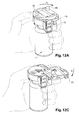
Figure 12A is a perspective view of the adaptor ofFigure 2 coupled with a vial when opened by a user. -
Figure 12B is a cross-section view of the adaptor ofFigure 2 coupled with a vial when a user withdraws a dose from the vial. -
Figure 12C is a perspective view of the adaptor ofFigure 2 coupled with a vial when closed by a user. - For purposes of the description hereinafter, the terms "upper", "lower", "right", "left", "vertical", "horizontal", "top", "bottom", "lateral", "longitudinal", and derivatives thereof shall relate to the invention as it is oriented in the drawing figures.
- With reference to
Figure 2 is shown anadaptor 10 in accordance with an embodiment of the invention, intended to be coupled on amultidose vial 1 as shown onFigures 1A-1C . Theadaptor 10 comprises a grippingmember 20 intended to secure the adaptor onto thevial 1, acounting ring 30 intended to provide information on the number of doses of product already withdrawn from thevial 1 and/or still left inside thevial 1, acap 40, intended to be snap-fitted to the grippingmember 20, a pierceableelastomeric piece 50 intended to be accommodated in thecap 40, and acover 60 intended to prevent or allow access to theopening 3a of thevial 1, once theadaptor 10 is coupled to thevial 1. - With reference to
Figure 2 , the grippingmember 20 will now be described in detail. The grippingmember 20 comprises aU-shaped body 21, having a partiallytubular wall 22 with a height suitable for surrounding thecollar 3 of the vial 1 (seeFigures 11A-11B ). The gripping member further comprises twofree ends 22a corresponding to the ends of the branches of the U, theU-shaped body 21 therefore forming a clipping member. Close to eachfree end 22a, thetubular wall 22 is provided on its outer surface with radial pegs 23 (only one being visible onFigure 2 ). Eachfree end 22a is further provided with a distal front projection forming aradial rim 24. - Still with reference to
Figure 2 , thecounting ring 30 is made of aflat cylinder 31 provided with a plurality of outerradial teeth 32 distributed along itsperiphery 31a. Theflat cylinder 31 is further provided with acentral hole 33 dimensioned and shaped so as to fit around radial outer pegs 47of thecap 40, as shown onFigures 4-6 . In the example shown onFigures 2 to 10 , theadaptor 10 is intended to be coupled to amultidose vial 1 filled with ten doses of product. As a consequence, thecounting ring 30 is provided with information data corresponding to these ten doses of product to be withdrawn from thevial 1. Theflat cylinder 31 is thus provided with printeddigits 34 indicating thenumbers 1 to 10, these digits being regularly distributed along the circumference of theflat cylinder 31. - With reference to
Figures 3 and 4 , thecap 40 will now be described in detail. Thecap 40 comprises atransversal wall 41 having a substantially circular shape except acorner 41a, and arear extension 41b. Afront rim 42 is extending from the front of thetransversal wall 41 in the distal direction. AU-shaped skirt 43 also extends from thetransversal wall 41 in the distal direction, the free ends 43a of the U forming afront opening 43b of theskirt 43. Close to eachfree end 43a, theskirt 43 is provided on its outer surface with fourrecesses 43c (only two being visible onFigure 2 ) and anotch 43d immediately nearby thetransversal wall 41. The circulartransversal wall 41 is provided with acentral access port 44 and with afront side hole 45. Thetransversal wall 41 is further provided in itscorner 41a with acorner hole 46 surrounded by threeopenings access port 44 is designed to accommodate a needle and is described as aneedle access port 44. - With reference to
Figures 4 to 6 , the proximal face of thetransversal wall 41 is provided with three radialouter pegs 47 and theU-shaped skirt 43 is provided on its inner wall with a corner transversal rim 48having acentral hole 48a that faces thecorner hole 46. Thecap 40 is sized and shape for receiving thecounting ring 30 and the grippingmember 20. As shown onFigures 5 and 6 , thecounting ring 30 is plugged inside thefront rim 42 thanks to the radial outer pegs 47. - Moreover, the
U-shaped skirt 43 of thecap 40 is aligned with theU-shaped element 21 of the grippingmember 20 when the different elements of theadaptor 10 are assembled. With reference toFigures 4 to 6 , theneedle access port 44 consists in alongitudinal wall 44a extending from the distal face of thetransversal wall 41 and having aninner surface 44b. Theinner surface 44b comprises aninner ring 44c having adistal abutment surface 44d present on the whole circumference of thelongitudinal wall 44a as shown onFigure 6 and defining three inner radial pegs 44c extending into theneedle access port 44. - With references to
Figures 7A and 7B , the pierceableelastomeric piece 50 will now be described in detail. Theelastomeric piece 50 has globally the shape of a cylinder with a longitudinal axis L and is intended to be accommodated inside theneedle access port 44 as shown onFigure 8 . In other embodiments not shown, the elastomeric piece could have globally the shape of a cube, a pyramid or a cylinder with a non-circular base. It comprises arecess 51 opened in the proximal direction, aproximal surface 52, adistal surface 53 and anouter wall 54. Therecess 51 with itsproximal opening 51a comprises an innerlongitudinal surface 51b and abottom surface 51c provided with acentral protrusion 55. Theproximal surface 52 of theelastomeric piece 50 is slopped distally toward the center of therecess 50, preferably with an angle of 45° to 75° regarding the longitudinal axis L and is linked to the innerlongitudinal surface 51b by achamfer 52 a : a bull nose in the present case. Thedistal surface 53 defines aprotruding part 53a that is extending distally. Theouter wall 54, which links thedistal surface 53 with theproximal surface 52, comprises acircular groove 56 defining aproximal shoulder 57, both circular groove and shoulder extending on the whole circumference of thelongitudinal wall 54 as shown onFigure 7B . Thecircular groove 56 is intended to be engaged with the inner radial pegs 44c of theneedle access port 44 and theshoulder 57 is intended to contact theabutment surface 44d of theneedle access port 44 when the pierceableelastomeric piece 50 is assembled in thecap 40 as it can be seen onFigure 8 . - In the embodiment shown on
Figures 7-8 , the ratio between the height of thecentral protrusion 55 of pierceableelastomeric piece 50 regarding the height of therecess 51 is about 0.2 while the ratio between the width of thecentral protrusion 55 regarding the width of saidrecess 51 is about 0.6. In the embodiment shown onFigures 7A and 7B , therecess 51 has a diameter of 3 mm and a height of 2.4 mm. The distance between thebottom surface 51c of therecess 51 and thedistal surface 53 of the elastomeric piece is about 2.8 mm. This distance should be adapted to the length of the needle lumen that will pierced the septum in order to preventambiant air to be sucked inside thevial 4 when the needle is removed from the pierceableelastomeric piece 50. - As it can be seen on
Figure 8 , the height of the pierceable elastomeric part is slightly higher than the height of theneedle access port 44 and theprotruding part 53a of the pierceable elastomeric piece is projected beyond the distal part of thelongitudinal wall 44a of theneedle access port 44. This allows theprotruding part 53a to to contact and deform theouter surface 4a of theseptum 4 when theadaptor 10 is mounted onto a medical container as it is shown onFigure 11B . In other words, theouter surface 4a of theseptum 4 is engaged by theprotrusion part 53a. In others embodiments not shown, the ratio of the height of therecess 51 regarding its width is comprised between 0.3 to 0.7, while the ratio between the height of thecentral protrusion 55 and the height of the recess is comprised between 0.1 to 0.3 and a ratio between the width of the central protrusion and the width of the recess is about 0.3 to 0.7. - Suitable materials for the pierceable
elastomeric piece 50 of the adaptor of the invention include natural rubber, acrylate-butadiene rubber, cis-polybutadiene, chlroro or bromobutyl rubber, chlorinated polyethylene elastomers, polyalkylene oxide polymers, ethylene vinyl acetate, fluorosilicone rubbers, hexafluoropropylene-vinylidenefluoride-tetrafluoroethyleneterpolymers, butyl rubbers, polyisobutene, synthetic polyisoprene rubber, silicone rubbers, styrene-butadiene rubbers, tetrafluoroethylene propylene copolymers, thermoplastic-copolyesters, thermo-plastic elastomers, or the like or a combination thereof. - Preferably, the elastomeric piece is self-resealing and it automatically and rapidlycloses the hole produced by the piercing of the needle" for example in less than 0.5 seconds, once the needle is removed from the elastomeric piece. This automatic closure step may occur a high number of times, in particular as many times as necessary for removing the number N doses of product initially present in the
multidose vial 1. Suitable materials for self-resealing pierceable elastomeric piece include synthetic polyisoprene, natural rubber, silicone rubber, thermo-plastic elastomers, or the like or a combination thereof. - The
cover 60 will now be described in detail with reference toFigures 2 ,8 ,9A and 9B . Thecover 60 comprises asheet 61 having substantially the shape of thetransversal wall 41 of thecap 40, with afront portion 61a, acentral portion 61b, arear portion 61c and acorner 61d on a side of therear portion 61c. When thecover 60 is mounted onto thecap 40 in a close position (Figure 8 and9A ), thefront portion 61a is intended to be aligned with thefront rim 42, thecentral portion 61b is intended to cover theneedle access port 44 and the rear portion is intended to cover therear extension 41b. Considering the proximal face of thesheet 61 shown onFigures 2 and9A , thefront portion 61a of thecover 60 comprises afront hole 65 intended to face thefront side hole 45 of thetransversal wall 41 of thecap 40 as well as a pushingsurface 62 located on a side of thefront portion 61a intended to be in contact with the thumb of a user when theadaptor 10 is in a used-position, as it will be described below with reference toFigure 12 . In the present embodiment, this pushing surface is substantially curved and turned toward the proximal direction and the front portion of thecover 60. Thecentral portion 61b consists in aplanar portion 64 defining a space for writing data or sticking a label. On the same side than the pushingsurface 62, therear portion 61c of thesheet 61 is provided with a guidingmember 68, for example a stud extending proximally and anoptional arrow 69 that can be present for indicating the direction of the rotation of thecover 60 when theadaptor 10 is in a used-potion. In the present case, the arrow indicates the clockwise direction. - In this preferred embodiment, both the guiding
member 68 and the pushingsurface 62 must be significantly offset to thecorner 61d. Preferably, the pushingsurface 62 is located as far as possible from thecorner 61d, while the guidingmember 68 could be located slightly closer to that corner i.e. not at the extremity of thesheet 61. For example, the ratio between the distance of thecorner 61d to the guidingmember 68 and the distance of thecorner 61d to the center C of thesheet 61 may range from 1.5 and 0.75. - More precisely, as the
cover 60 is considered to have a substantially circular shape defining a center C located on theplanar portion 64, therefore the pushingsurface 62 is localized at about 180° from thecorner 61d, while the guidingmember 68 is placed approximately at 270° clockwise. Thefront hole 65 is located approximately at 135° clockwise from thecorner 61d, but any other convenient area of thecover 60 could be also considered. - In other embodiments not shown, the guiding member could have another form such as a hole, a lug or a ring and the distal surface bulges from the
sheet 61. - Now considering the distal face of the
sheet 61 as shown onFigure 9B , thefront portion 61a includes alongitudinal extension 63 directed in the distal direction and provided with aradial peg 63a (Figure 2 and9B ). When thecover 60 is assembled onto thecap 40 in a close position, thepeg 63a of the extension 63is engaged with thenotch 43d of theU-shaped skirt 43, as it can be seen onFigure 10 , thereby forming locking means. - Furthermore, as shown on
Figures 9A and 9B , theplanar portion 64 is provided with awindow 64a having aflexible leg 64b substantially parallel to thesheet 61 and comprising adistal tooth 64c. Thedistal tooth 64c comprises a straight surface and a slopped surface. When thecover 60 is assembled with thecap 40 in a close position, thedistal tooth 64c is capable to cooperate with theopenings circular rim 64d comprising three segments is intended to face theneedle access port 44 of thecap 40 as well as theproximal opening 51a of the pierceableelastomeric piece 60, when the cover is assembled on theadaptor 10 and in a close position. More generally the discontinuouscircular rim 64d can comprise at least one discontinuous segment. Thecorner 61d of thesheet 61 is provided with ashaft 66 extending in the distal direction having a distalouter rim 66a at its extremity, as shown onFigure 9B . Additionally, asemi-gear wheel 67 is present on theshaft 66. The semi-gear 67 is proximally spaced from the distalouter rim 66a and has outer radial teeth only on a part of its circumference. - The
sheet 61 may be made of any material such as high-density polyethylene, polypropylene, polyvinyl chloride, acrylonitrile-butadiene-styrene (ABS), silicon resin or any other rigid polymer. Alternatively, materials such as metal, wood or glass may be used. - The use of an
adaptor 10 once connected with a vial ofFigures 1A-1C will now be explained with reference toFigures 11 to 12 . - With reference to
Figures 11A and 11B , theadaptor 10 is shown once coupled to avial 1 and closed by thecover 60. In this view, the grippingmember 20 has been mounted on thecollar 3 of the vial and theradial rims 24 now surround thecollar 3, thereby securing theadaptor 10 on thevial 1. In this coupled position of theadaptor 10 on thevial 1, theneedle access port 44, in which is lodged the pierceableelastomeric piece 60, is aligned with theseptum 4 and with theopening 3a of thevial 1. - The pierceable
elastomeric piece 50 extends through thecentral hole 33 of thecounting ring 30 to come in close contact with theouter surface 4a of theseptum 4 of thevial 1. In particular, the protrudingpart 53a even distorts theouter surface 4a of theseptum 4, as can be seen onFigure 11B . The pierceableelastomeric piece 50 is maintained in theneedle access port 44 by the engagement of the inner radial pegs 44c of the needle access port in itscircular groove 56. Moreover, a proximal pressure is applied by the protrudingpart 53a on theouter surface 4a of theseptum 4. Any proximal translation of the pierceableelastomeric piece 50 regarding thecap 40 is prevented as theshoulder 57 is resting on theabutment surface 44d of theneedle access port 44. The inner radial pegs 44c together with thecircular groove 56, and theabutment surface 44d together with theshoulder 57 therefore form attaching means for maintaining theelastomeric piece 50 into theneedle access port 44. - The attaching means 44c, 56, 57 and 44d appropriately connect the
elastomeric piece 50 and also allow a fast and straightforward assembly of theelastomeric piece 50 inside theneedle access port 44. Indeed, theelastomeric piece 50 can be presented by the distal face of thecap 40, proximally pushed into theneedle access port 44. It is easily deformed in the needle access port thanks to its elastomeric properties which allows the inner radial pegs 44c to pass along the distal portion of thelongitudinal wall 54 up to thecircular groove 56. Theshoulder 57 rests on theabutment surface 44d of theneedle access port 44 and prevents any further proximal translation: theelastomeric piece 50 is correctly assembled with thecap 40. - With reference to
Figures 8 ,11A and 11B , theflat cylinder 31 of the counting ring is snap-fitted on thecap 40 and thecentral hole 33 is engaged with the radial outer pegs 47 of thecap 40, is blocked in the distal direction. Therefore, theflat cylinder 31 is capable of rotating with respect to said radial outer pegs 47. - Additionally, the
cap 40 is itself snap-fitted on the grippingmember 20 thanks to therecesses 43c engaged with the radial pegs 23 present on thetubular wall 22 ofU-shaped element 21 of the grippingmember 20. As a consequence, thecap 40 is fixed with respect to the grippingmember 20. In an embodiment not shown, thecap 40 and theU-shaped element 21 can be integrated together and form a single element, namely the gripping member. - According to the
Figures 11A and 11B , thecover 60 is linked to thecap 40 as theshaft 66 is plugged into thecorner hole 46 of thetransversal wall 41 and snap-fitted into the cornertransversal rim 48 as it can be seen onFigures 4 and9B . Theshaft 66 can rotate withincorner hole 46, in a clockwise direction indicated by thearrow 69. Theshaft 66 together with the cornertransversal rim 48 therefore form a hinge at thecorners cap 40 and thecover 60, respectively. This hinge (46, 66) allows the planar rotation of thecover 60 from a first position closing theneedle access port 44 to a second position giving access to theneedle access port 44. For a straightforward and efficient rotation, this hinge is located on a side of thecover 60. More precisely, in the present embodiment, the hinge (46, 66) is located on the rear portion of thecover 60, i.e. on the corner 61d.Thecover 60, thecap 40 and the hinge (46,66) therefore form a closing system for thevial 1. - The
cover 60 is maintained in its first, close position as thepeg 63a engages the notch 63d of thecap 40, thepeg 63a and thenotch 43d serving as locking means for preventing any undesired rotation of thecover 60. Thecover 60 therefore allows an efficient protection against dust and contamination of theelastomeric piece 50 and thus of theseptum 4 of thevial 1, when thevial 1 is not in used. - Usually the vials containing vaccines are stored at cold temperature (2-8°C) and, when a user takes a vial out of the refrigerated storage, some condensation could appear on the surface of the vial septum and/or on the surface of
adaptor 10 as it is exposed to ambient temperature. The discontinuouscircular rim 64d of thecover 60 is in tight contact with thetransversal wall 41 of thecap 40, in particular with the portion located around theneedle access port 44, when thecover 60 is in close position. This prevents any condensation from being trapped into therecess 51 while effectively closing theneedle access port 44 as this discontinuouscircular rim 64d allows a gas exchange between therecess 51 and the outside environment. - Furthermore, the distally slopped
surface 52 of theelastomeric piece 50 shown onFigures 7A and 7B is also designed to guide the condensation towards therecess 51 therefore limiting the trapping of the condensation between theelastomeric piece 50 and theneedle access port 44. The growth of bacteria around theelastomeric piece 50 is therefore widely prevented, as this space is kept dry from condensation. The condensation is not trapped but directed towards therecess 51 where it can be evaporated, even when thecover 60 is closed thanks to thediscontinuous rim 64d. - Thanks to its configuration, the
protrusion 55 of therecess 51 remains a dry and clean pierceable surface as the limited amount of condensation is restricted to a portion of the bottom surface around theprotrusion 55. The discontinuouscircular rim 64d, the distally sloppedsurface 52 and theprotrusion 55 are thus all designed in such a way to prevent or to limit contamination due to bacteria growing in condensation nearby the pierceableelastomeric piece 50 and theseptum 4. - When the user needs to withdraw a first dose of product, he grasps the
adaptor 10 coupled to thevial 1, his index finger contacting theU-shaped skirt 43 and therear extension 41b of thecap 40 as can be seen onFigure 12A . The thumb is placed on the pushingsurface 62 of thecover 60, while the other fingers are gripping thevial 1. To move thecover 60 from its first close position to a second open position, the user just pushes the pushing surface with his thumb in direction A, therefore disengaging thepeg 63a of thecover 60 from thenotch 43d of thecap 40 as shown onFigure 10 . This movement leads to a planar, clockwise rotation of thecover 60 above thecap 40. During this rotation, thedistal tooth 64c of thecover 60 is engaged successively with theopening tooth 64c has a slopped surface inclined toward the direction of the rotation as seen onFigure 9B . Thanks to its straight surface in the counter direction of the rotation, theflexible leg 64b and thedistal tooth 64c prevent thecover 60 from moving in the counterclockwise direction, and therefore form, together with theopenings adaptor 10 in a safe and appropriate manner, even if he does not have received any particular training. - To complete the movement of the
cover 60 to its second, open position, the user sustains the pressure on the pushingsurface 62 until thecover 60 is at 180° of its first position and allows the access to theneedle access port 44. - Then the user can withdraw a dose of the pharmaceutical product stored in the
vial 1. This can be done by turning the vial over, the proximal face of thetransversal wall 41 now substantially facing the ground as shown onFigure 12B . The user then pierces both theelastomeric piece 50 and theseptum 4 of thevial 1 with theneedle 71 of aninjection device 70. Thanks to theproximal surface 52 of theelastomeric piece 50, slopped distally towards the center of therecess 51, theneedle 71 is guided into therecess 51 to pierce directly thecentral protrusion 55. Thanks to the appropriate inclination of the sloppedproximal surface 52, the risk of accidental pricking of the user by ripping of the needle on the needle access port is significantly reduced. When theneedle 71 pierces theelastomeric piece 50 and theseptum 4, it directly penetrates the dry andclean protrusion 55, and is not contaminated by any dust or bacteria developing in condensation water. - The user can then fill the
injection device 70 by withdrawing a dose of the pharmaceutical product contained in the vial. Even if the inside of thevial 1 is under vacuum after removal of theneedle 71, no outside air is sucked inside. Indeed thedistal surface 53 of theelastomeric piece 50 and in particular theprotruding part 53a engages thesurface 4a of theseptum 4. The interface between theelastomeric piece 50 and theseptum 4 is preserved from outside air, condensation and contaminants; theelastomeric piece 50 and theseptum 4 of thevial 1 behave has a single piece. Theelastomeric piece 50 therefore allows theseptum 4 of the vial to reseal before the complete removal of theneedle 71 and prevent sucking of the outside air into the vial. - With the
cover 60 in an open position, the elastomeric piece is directly exposed to outside contaminants. Nonetheless, any direct contact is avoided with the bottom surface of the elastomeric piece, intended to be pierced, even if the user's fingers or any contaminated surface might come in contact with the pierceableelastomeric piece 50. Therecess 51 and theproximal surface 52 prevent the user's finger or any other contaminated surface to contact thebottom surface 53. Moreover, if any dust would penetrate the recess or if any condensation would form, they will mainly be restricted around theprotrusion 55, therefore keeping theprotrusion 55, intended to be pierced, substantially away from contaminants. Therecess 51 therefore provides an additional and valuable protection against the contamination of the inside of thevial 1. This is particularly important when theadaptor 10 is used in locations where the user has a limited access to efficient soap or sterilizing solution. - After the
injection device 70 is filled with the pharmaceutical product, theadaptor 10 can be closed. Performing this step implies moving thecover 60 from the second open position back to its first close position. The pushingsurface 62 of the cover is now in the opposite direction as regards of the thumb of the user who has to pull on thestud 68 with his thumb for moving thecover 60 in a planar clockwise movement towards its close position. In this position, thepeg 63a of thecover 60 is re-engaged in thenotch 43d of the cap 40and thecover 60 is locked. - The position of the pushing
surface 62 on an opposite side from the hinge (46, 66) and preferably as far as possible, allows a leverage effect resulting in very smooth and easy movement of thecover 60 at the beginning of its rotation. The position of the guidingmember 68, offset from thecorner 61d but not at the extremity of thesheet 61, allows closing thecover 60 with a limited movement of the user's thumb. - The pushing
surface 62 and thestud 68 therefore permit a relay as an interface for the user's thumb. The pushingsurface 62 allows the user to rotate thecover 60 for the first 180° (the opening), while thestud 68 allows the user to rotate thecover 60 for the last 180° (the closing). The pushing surface can also help the user for the very last degrees of the rotation, as it is almost came back to its first position in front of the thumb. Thestud 68 can also be used during the opening, for example if the user is unable to grasp thevial 1 in an appropriate way. These two interfaces, namely the pushingsurface 62 and the guidingmember 68 therefore allows a straightforward and reliable operation of thecover 60. - During the whole operation, only a single hand is required to open and close the
cover 60 of theadaptor 10. Thanks to the hinge formed by theshaft 66 coupled with thecorner hole 46 of thecap 40, together with the pushingsurface 62 and thestud 68, the cover 60can be moved with a single thumb, the other fingers grasping both the vial and the adaptor. As a result, the user can grasp with its second hand any other required material, such as an injection device. - Moreover, the clockwise rotation indicated by the
arrow 69 present on the cap is forced by theunidirectional means cover 60 and with therear extension 41b of thecap 40 and do not contact neither thecap 40 nor theelastomeric piece 50. This leads to a safe and straightforward operation with limited contamination, as the user is prevented from touching the pierceableelastomeric piece 50. The user is therefore preserved from any accidental pricking or movement and does not require particular training to properly operate theadaptor 10. - Indeed, the closing system comprising the
transversal wall 41, thecover 61 and the hinge (46, 66) could be used with any container intended to be manipulated with a single hand, particularly in the medical area but also in the fields of cosmetics, food or industry. The system according to the present embodiment is included on an adaptor mounted on a container, but could be directly integrated on the container, therefore providing a container "ready-to-use" without the mounting step. - The closing system of the present invention allows a safe and straightforward manipulation even when operated by a untrained user.
Claims (15)
- A closing system for a container to be hold with a single hand, said closing system comprising:- a cap (40) comprising a a skirt (43) and a transversal wall (41) provided with an access port (44),- a cover (60) substantially parallel to said cap and comprising a guiding member (68) intended to be used by a user to manipulate said cover,- a hinge (46, 66) allowing a planar rotation of the cover (60) regarding the cap (40) from a first position closing said access port (44) to a second position giving access to the access port (44).
- A closing system according to claim 1, wherein the hinge (46, 66) comprises a shaft (66) extending in the distal direction from the cover (60), and a corner hole (46) provided in the transversal wall (41).
- A closing system according to claim 1 or 2, wherein said guiding member (68) is a stud.
- A closing system according to any one of claims 1 to 3, wherein said cover (60) further comprises a pushing surface (62).
- A closing system according to any one of claims 1 to 4, wherein the hinge (46, 66) is located on a side of said cover (60).
- A closing system according to any one of claims 1 to 5, wherein the hinge (46, 66) is located on a rear portion (61c) of said cover (60).
- A closing system according to claim 4 or 6, wherein the pushing surface (62) is located on a front portion (61a) of said cover (60).
- A closing system according to any one of claims 3 to 7 wherein the stud (68) is located on a rear portion (61c) of said cover (60).
- A closing system according to any one of claims 3 to 8, wherein the stud (68) is located on a first side of said cover (60), while the hinge (46, 66) is located on the opposite, second side of said cover (60).
- A closing system according to any one of claims 3 to 9, wherein the pushing surface (62) and the stud (68) are located on the same first side of said cover (60).
- A closing system according to any one of claims 1 to 10, further comprising unidirectional means (64b, 64c, 49a, 49b, 49c) only allowing a clockwise or a counterclockwise rotation.
- A closing system according to claim 11, wherein said unidirectional means comprises a tooth (64c) located on a flexible leg (64b) substantially parallel to said cover (60), and three openings (49a, 49b, 49c) located on said transversal wall 41.
- A closing system according to any one of claim 1 to 12, further comprising locking means (63a, 43d) to maintain the cover in a close position.
- A closing system according to claim 13, wherein said locking means comprises a peg (63a) located on a longitudinal extension (63) of said cover (60), and a notch (43d) located on the skirt (43).
- A closing system according to any one of claims 1 to 14, wherein said transversal wall (41) comprises a rear extension (41b) intended to block the user's index finger when said user grasps said closing system.
Priority Applications (15)
| Application Number | Priority Date | Filing Date | Title |
|---|---|---|---|
| EP13305096.3A EP2759486A1 (en) | 2013-01-28 | 2013-01-28 | Closing system for a container |
| PCT/EP2013/066161 WO2014020100A2 (en) | 2012-08-03 | 2013-08-01 | Closing system for a container |
| CN201320572806.9U CN203469036U (en) | 2012-08-03 | 2013-08-01 | Closing system for containers held by single hand |
| ES13744548T ES2897665T3 (en) | 2012-08-03 | 2013-08-01 | Closing system for a container |
| CN201310421172.1A CN103565639B (en) | 2012-08-03 | 2013-08-01 | Closed-system for container |
| SG11201408427RA SG11201408427RA (en) | 2012-08-03 | 2013-08-01 | Closing system for a container |
| AP2015008201A AP2015008201A0 (en) | 2012-08-03 | 2013-08-01 | Closing system for a container |
| EP13744548.2A EP2879967B1 (en) | 2012-08-03 | 2013-08-01 | Closing system for a container |
| MX2014014786A MX2014014786A (en) | 2012-08-03 | 2013-08-01 | Closing system for a container. |
| JP2015524785A JP6271547B2 (en) | 2012-08-03 | 2013-08-01 | Container closure system |
| KR1020157002504A KR102079412B1 (en) | 2012-08-03 | 2013-08-01 | Closing system for a container |
| CN201380041182.0A CN104520205A (en) | 2012-08-03 | 2013-08-01 | Closing system for a container |
| IN10517DEN2014 IN2014DN10517A (en) | 2012-08-03 | 2013-08-01 | |
| US14/419,070 US10335347B2 (en) | 2012-08-03 | 2013-08-01 | Closing system for a container |
| ZA2014/09211A ZA201409211B (en) | 2012-08-03 | 2014-12-15 | Closing system for a container |
Applications Claiming Priority (1)
| Application Number | Priority Date | Filing Date | Title |
|---|---|---|---|
| EP13305096.3A EP2759486A1 (en) | 2013-01-28 | 2013-01-28 | Closing system for a container |
Publications (1)
| Publication Number | Publication Date |
|---|---|
| EP2759486A1 true EP2759486A1 (en) | 2014-07-30 |
Family
ID=47750589
Family Applications (1)
| Application Number | Title | Priority Date | Filing Date |
|---|---|---|---|
| EP13305096.3A Withdrawn EP2759486A1 (en) | 2012-08-03 | 2013-01-28 | Closing system for a container |
Country Status (1)
| Country | Link |
|---|---|
| EP (1) | EP2759486A1 (en) |
Citations (6)
| Publication number | Priority date | Publication date | Assignee | Title |
|---|---|---|---|---|
| US1998373A (en) * | 1933-01-17 | 1935-04-16 | Solomon A Love | Closure cap |
| US3352445A (en) * | 1966-07-18 | 1967-11-14 | Cochin Solomon | Captive closure for a container |
| US4676788A (en) * | 1985-11-27 | 1987-06-30 | E. I. Du Pont De Nemours And Company | Guide member for a vial |
| US5405031A (en) * | 1992-11-19 | 1995-04-11 | Firma Pohl Gmbh & Co. Kg | Closure for a medicine bottle |
| WO1998009579A1 (en) * | 1996-09-04 | 1998-03-12 | The West Company, Incorporated | Reclosable vial closure |
| US20080245796A1 (en) * | 2007-04-05 | 2008-10-09 | Owens-Illinois Prescription Products Inc. | Child-resistant dispensing package |
-
2013
- 2013-01-28 EP EP13305096.3A patent/EP2759486A1/en not_active Withdrawn
Patent Citations (6)
| Publication number | Priority date | Publication date | Assignee | Title |
|---|---|---|---|---|
| US1998373A (en) * | 1933-01-17 | 1935-04-16 | Solomon A Love | Closure cap |
| US3352445A (en) * | 1966-07-18 | 1967-11-14 | Cochin Solomon | Captive closure for a container |
| US4676788A (en) * | 1985-11-27 | 1987-06-30 | E. I. Du Pont De Nemours And Company | Guide member for a vial |
| US5405031A (en) * | 1992-11-19 | 1995-04-11 | Firma Pohl Gmbh & Co. Kg | Closure for a medicine bottle |
| WO1998009579A1 (en) * | 1996-09-04 | 1998-03-12 | The West Company, Incorporated | Reclosable vial closure |
| US20080245796A1 (en) * | 2007-04-05 | 2008-10-09 | Owens-Illinois Prescription Products Inc. | Child-resistant dispensing package |
Similar Documents
| Publication | Publication Date | Title |
|---|---|---|
| EP2948122B1 (en) | Adaptor for coupling with a medical container | |
| US10751252B2 (en) | Adaptor for coupling with a medical container | |
| US5067948A (en) | Safety, packaging, injection and disposal system for pre-filled pharmaceutical vials | |
| EP2879967B1 (en) | Closing system for a container | |
| JP6240317B2 (en) | Assembly comprising an adapter and a blister for coupling to a medical container | |
| JP6051306B2 (en) | Dosing count device for coupling with medical containers | |
| US20150320639A1 (en) | Adaptor for Multidose Medical Container | |
| JP6397900B2 (en) | Assembly for coupling adapter to medical container | |
| EP2692324A1 (en) | Adaptor for coupling with a medical container | |
| EP2759486A1 (en) | Closing system for a container | |
| OA17983A (en) | Closing system for a container. | |
| US20090178998A1 (en) | Closed cover for medicinal vial | |
| SG192309A1 (en) | Adaptor for coupling with a medical container |
Legal Events
| Date | Code | Title | Description |
|---|---|---|---|
| PUAI | Public reference made under article 153(3) epc to a published international application that has entered the european phase |
Free format text: ORIGINAL CODE: 0009012 |
|
| 17P | Request for examination filed |
Effective date: 20130128 |
|
| AK | Designated contracting states |
Kind code of ref document: A1 Designated state(s): AL AT BE BG CH CY CZ DE DK EE ES FI FR GB GR HR HU IE IS IT LI LT LU LV MC MK MT NL NO PL PT RO RS SE SI SK SM TR |
|
| AX | Request for extension of the european patent |
Extension state: BA ME |
|
| STAA | Information on the status of an ep patent application or granted ep patent |
Free format text: STATUS: THE APPLICATION HAS BEEN WITHDRAWN |
|
| 18W | Application withdrawn |
Effective date: 20140721 |