EP2759471A2 - Fluidfoil - Google Patents
Fluidfoil Download PDFInfo
- Publication number
- EP2759471A2 EP2759471A2 EP13196929.7A EP13196929A EP2759471A2 EP 2759471 A2 EP2759471 A2 EP 2759471A2 EP 13196929 A EP13196929 A EP 13196929A EP 2759471 A2 EP2759471 A2 EP 2759471A2
- Authority
- EP
- European Patent Office
- Prior art keywords
- fluidfoil
- leading edge
- deflected
- edge zone
- deflected region
- Prior art date
- Legal status (The legal status is an assumption and is not a legal conclusion. Google has not performed a legal analysis and makes no representation as to the accuracy of the status listed.)
- Granted
Links
Images


Classifications
-
- F—MECHANICAL ENGINEERING; LIGHTING; HEATING; WEAPONS; BLASTING
- F01—MACHINES OR ENGINES IN GENERAL; ENGINE PLANTS IN GENERAL; STEAM ENGINES
- F01D—NON-POSITIVE DISPLACEMENT MACHINES OR ENGINES, e.g. STEAM TURBINES
- F01D5/00—Blades; Blade-carrying members; Heating, heat-insulating, cooling or antivibration means on the blades or the members
- F01D5/12—Blades
- F01D5/14—Form or construction
- F01D5/141—Shape, i.e. outer, aerodynamic form
- F01D5/145—Means for influencing boundary layers or secondary circulations
-
- B—PERFORMING OPERATIONS; TRANSPORTING
- B64—AIRCRAFT; AVIATION; COSMONAUTICS
- B64C—AEROPLANES; HELICOPTERS
- B64C11/00—Propellers, e.g. of ducted type; Features common to propellers and rotors for rotorcraft
- B64C11/16—Blades
- B64C11/18—Aerodynamic features
-
- B—PERFORMING OPERATIONS; TRANSPORTING
- B64—AIRCRAFT; AVIATION; COSMONAUTICS
- B64D—EQUIPMENT FOR FITTING IN OR TO AIRCRAFT; FLIGHT SUITS; PARACHUTES; ARRANGEMENT OR MOUNTING OF POWER PLANTS OR PROPULSION TRANSMISSIONS IN AIRCRAFT
- B64D27/00—Arrangement or mounting of power plants in aircraft; Aircraft characterised by the type or position of power plants
- B64D2027/005—Aircraft with an unducted turbofan comprising contra-rotating rotors, e.g. contra-rotating open rotors [CROR]
-
- Y—GENERAL TAGGING OF NEW TECHNOLOGICAL DEVELOPMENTS; GENERAL TAGGING OF CROSS-SECTIONAL TECHNOLOGIES SPANNING OVER SEVERAL SECTIONS OF THE IPC; TECHNICAL SUBJECTS COVERED BY FORMER USPC CROSS-REFERENCE ART COLLECTIONS [XRACs] AND DIGESTS
- Y02—TECHNOLOGIES OR APPLICATIONS FOR MITIGATION OR ADAPTATION AGAINST CLIMATE CHANGE
- Y02T—CLIMATE CHANGE MITIGATION TECHNOLOGIES RELATED TO TRANSPORTATION
- Y02T50/00—Aeronautics or air transport
- Y02T50/60—Efficient propulsion technologies, e.g. for aircraft
Definitions
- Each deflected region 45 is also provided with several tapering features.
- the depth of the deflected region 45 i.e. the vertical distance between the suction surface 43 within a deflected region 45 and the suction surface 43 at a deflection interface 48 between a deflected region 45 and a non-deflected region 47
- the spanwise tapers form two side walls 49, each having a consistent gradient.
Landscapes
- Engineering & Computer Science (AREA)
- Physics & Mathematics (AREA)
- Fluid Mechanics (AREA)
- Aviation & Aerospace Engineering (AREA)
- Mechanical Engineering (AREA)
- General Engineering & Computer Science (AREA)
- Structures Of Non-Positive Displacement Pumps (AREA)
- Separation Using Semi-Permeable Membranes (AREA)
- Ultra Sonic Daignosis Equipment (AREA)
- Fats And Perfumes (AREA)
Abstract
Description
- The present invention relates to fluidfoils and engines incorporating fluidfoils. The invention may be particularly useful when used with open-rotor gas turbine engines. For convenience the background section below references open-rotor configurations by way of example. The invention is not however limited to such uses and may be used in other applications, particularly those where the fluidfoil may have a relatively high angle of attack and where it is desirable to reduce noise and/or vortices leaving the fluidfoil.
- Certain open-rotor configurations utilise rotors designed to attain and maintain a fixed rate of rotation. In such cases the thrust provided by the rotor is controlled by varying the pitch of the blades (a higher angle of attack for increased thrust and a lower angle of attack decreased thrust). At higher angles of attack air separation at greater distances from the leading edge is more likely to occur. This is the result of a greater adverse pressure gradient encountered by air flowing towards the leading edge. Once the oncoming flow has insufficient momentum to overcome the pressure gradient it will separate. With greater separation distances from the leading edge, the wake produced by the blade is increased (increasing noise) and greater aerodynamic loss occurs (reducing efficiency). These characteristics may be particularly undesirable at take-off when high thrust (and therefore increased angle of attack) is required.
- According to a first aspect of the invention there is provided a fluidfoil optionally comprising a leading edge and optionally a leading edge zone behind the leading edge optionally extending spanwise over the full span of the fluidfoil, where the leading edge zone optionally comprises one or more deflected regions which optionally locally reduce the angle of attack of the fluidfoil.
- When the fluidfoil is in use, an area of the leading edge having a reduced angle of attack may increase the momentum of fluid approaching that area. In this way the distance from the leading edge at which flow separation occurs may be reduced. The increased momentum in the region of the deflected region may also entrain nearby flows, thereby reducing flow separation in regions of the leading edge zone that are conventional/non-deflected. By reducing the flow separation distance in advance of the leading edge, the wake caused by the fluidfoil may be reduced and so also the broadband noise produced. Further the decreased flow separation distance may also reduce overall lift loss and drag, improving efficiency. It may be for example that a slower fluidfoil speed than would otherwise be required would be sufficient to produce a given force. This may also have the additional benefit of further reducing noise.
- It is further noted that the deflected region may have a similar effect to an aerodynamic fence, blocking spanwise flow migration, thus reducing fluidfoil tip vortices.
- Throughout the remainder of this document optional features of the, some or each deflected region are for simplicity (except where otherwise specified) indicated via discussion of a single deflected region. As will be appreciated however, features discussed in relation to a single deflected region may also be applied to additional or indeed all deflected regions.
- In some embodiments the deflected region comprises a local modification to the surface contouring of the leading edge zone. It may therefore be possible to achieve the desired effect without attaching additional flow modifying components to the fluidfoil.
- In some embodiments the deflected region comprises a portion of the leading edge zone angled further towards the pressure surface of the fluidfoil than non-deflected regions of the leading edge zone which extend spanwise to either side and/or between each deflected region. In this way the deflected region may define a scoop with an associated leading edge defining a reduced angle of attack when compared to surrounding areas of the leading edge zone.
- In some embodiments the fluidfoil has a consistent angle of attack in the non-deflected regions. The combination of deflected and non-deflected regions may produce a preferred compromise between different performance envelopes of the fluidfoil. The non-deflected regions may be optimised in the normal way (e.g. efficient force production for important areas of the performance envelope), while the deflected regions assist in managing fluid flow at the leading edge and performance in particular operating regimes.
- In some embodiments there is no local chordwise extension of the leading edge associated with the deflected region. Likewise there may be no local chordwise retraction of the leading edge associated with the deflected region. Additionally or alternatively it may be that there is no local extension and/or retraction of the camber line associated with the deflected region. It may be for example that the curve of the leading edge along the span of the fluidfoil is maintained as it passes deflected and non-deflected regions of the leading edge zone. Additionally or alternatively it may be that a curve in the leading edge along the span of the fluidfoil remains positive in gradient rather than alternating between positive and negative.
- In some embodiments the extent of the deflected region decreases from the leading edge through the leading edge zone. This may create a blend (which may be gradual) into a main body of the fluidfoil which extends behind the leading edge zone. In this way the deflected region may have the desired effect on fluid impinging on the leading edge without unduly impacting on the flow of fluid over the remainder of the fluidfoil main body.
- In some embodiments the deflected region blends into a main body of the fluidfoil extending behind the leading edge zone and disappears. It may be advantageous for the deflected region to blend completely rather than continue into and/or through the main body.
- In some embodiments the depth of the deflected region tapers in one or both spanwise directions so as to blend with the respective non-deflected region of the leading edge zone. The deflected region may have a cross-section of substantially triangular form. The spanwise taper may be straight edged (with one consistent gradient or more than one gradient) or curved (convex, concave or a combination) or a combination of any of the above. A region of curved gradient may be particularly advantageous where the deflected and non-deflected regions meet.
- In some embodiments the depth of the deflected region tapers in a chordwise direction from a maximum at the leading edge so as to blend with the main body of the fluidfoil. In this way the deflected region may define an upwardly orientated ramp for fluid passing the leading edge on the suction side of the fluidfoil in the area of the deflected region. The chordwise taper may be straight edged (with one consistent gradient or more than one gradient) or curved (convex, concave or a combination) or a combination of any of the above.
- In some embodiments the spanwise width of the deflected region decreases in a chordwise direction from a maximum at the leading edge, through the leading edge zone, to no spanwise width at the interface of the leading edge zone with the main body.
- In some embodiments at least one deflected region is provided nearer to a tip than a root of the fluidfoil. In some embodiments at least one deflected region is provided beyond 80% and/or 90% of the distance from the root to the tip of the fluidfoil. In some embodiments the number of deflected regions increases from the root to the tip of the fluidfoil. Flow separation may be more likely to occur towards the tip of the fluidfoil.
- In some embodiments a pattern of deflected and non-deflected regions is provided spanwise along the leading edge zone. In some embodiments the pattern comprises alternating deflected and non-deflected regions.
- In some embodiments the fluidfoil is an open-rotor blade. The present invention may be particularly relevant to open-rotor. Open-rotor may be more susceptible to flow separation due to the thinness of the blades. Further noise may be a particular issue, potentially exacerbated by front rotor tip vortex and/or wake ingestion by the rear of a pair of contra-rotating rotors. The invention may also help to mitigate installation effect (where the incoming flow direction is not parallel to the rotation axis), especially in open-rotor blades. As will be appreciated however the invention is not limited to use with open-rotor blades. In other embodiments the fluidfoil may be a fan blade, compressor blade, turbine blade, propeller blade, wind turbine blade or ship propeller.
- According to a second aspect of the invention there is provided a gas turbine engine provided with one or more fluidfoils in accordance with the first aspect of the invention.
- In some embodiments the gas turbine engine utilises an open rotor configuration with at least one open rotor blade corresponding to the fluidfoil of the first aspect.
- In some embodiments the open rotor configuration comprises a contra-rotating pair of rotors, with at least one open rotor blade of the front-most rotor corresponding to the fluidfoil of the first aspect. As will be appreciated at least one open rotor blade of the rear-most rotor may alternatively or additionally correspond to the fluidfoil of the first aspect.
- The skilled person will appreciate that a feature described in relation to any one of the above aspects of the invention may be applied mutatis mutandis to any other aspect of the invention.
- Embodiments of the invention will now be described by way of example only, with reference to the figures, in which:
-
Figure 1 is a sectional side view of a gas turbine engine having contra-rotating propeller stages; -
Figure 2a is a top view of a portion of fluidfoil according to an embodiment of the invention; -
Figure 2b is a front view of the portion shown inFigure 2a ; -
Figure 2c shows section A-A in accordance withFigure 2a ; -
Figure 2d shows section B-B in accordance withFigure 2a ; -
Figure 3a shows a conventional fluidfoil not incorporating the present invention; -
Figure 3b shows the angle of attack of theFigure 3a fluidfoil; -
Figure 4a shows a fluidfoil in accordance with an embodiment of the invention; -
Figure 4b shows the angle of attack of theFigure 4a fluidfoil. - Referring to
Figure 1 a twin-spooled, contra-rotating propeller gas turbine engine is generally indicated at 10 and has a principal rotational axis 9. Theengine 10 comprises a core engine 11 having, in axial flow series, anair intake 12, anintermediate pressure compressor 14, a high-pressure compressor 15,combustion equipment 16, a high-pressure turbine 17, anintermediate pressure turbine 18, a free power (or low-pressure)turbine 19 and acore exhaust nozzle 20. Anacelle 21 generally surrounds the core engine 11 and defines theintake 12 andnozzle 20 and acore exhaust duct 22. Theengine 10 also comprises two contra-rotating propeller stages 23, 24 attached to and driven by thefree power turbine 19 viashaft 26. - The
gas turbine engine 10 works in a conventional manner so that air entering theintake 12 is accelerated and compressed by theintermediate pressure compressor 14 and directed into the high-pressure compressor 15 where further compression takes place. The compressed air exhausted from the high-pressure compressor 15 is directed into thecombustion equipment 16 where it is mixed with fuel and the mixture combusted. The resultant hot combustion products then expand through, and thereby drive the high-pressure, intermediate pressure andfree power turbines nozzle 20 to provide some propulsive thrust. The high-pressure, intermediate pressure andfree power turbines intermediate pressure compressors propellers propellers propellers - Referring now to
Figures 2a and 2b a portion of a fluidfoil is generally shown at 30. Thefluidfoil 31 has aleading edge 33, a leadingedge zone 35 immediately behind the leadingedge 33, amain body 37 immediately behind that and a trailingedge 39. The leadingedge zone 35 is positioned behind the leading edge 33 (along the camber line) and extends spanwise for the full length of the fluidfoil. The leadingedge zone 35 may therefore be considered to comprise a spanwise band behind the leadingedge 33. The fluidfoil has apressure surface 41 and asuction surface 43. - Within the leading
edge zone 35 are deflectedregions 45 andnon-deflected regions 47. The deflected 45 andnon-deflected regions 47 form an alternating repeating pattern in the spanwise direction. The leadingedge zone 35 encompasses the full depth of thefluidfoil 31, from and including thepressure surface 41 to and including thesuction surface 43, for the full extent of theleading edge zone 35. - The
non-deflected regions 47 contribute to the formation of a standard fluidfoil cross-sectional profile defined by the leadingedge 33,non-deflected region 47,main body 37 and trailingedge 39. This profile (A-A inFigure 2a ) is shown inFigure 2c (with a cross-section at the deflectedregion 35 corresponding to line B-B inFigure 2a shown in phantom). In thenon-deflected regions 37 the angle of attack is consistent (the same). - Where however deflected
regions 45 are provided, the standard fluidfoil cross-section is modified by a change in the contours of thepressure 41 andsuction 43 surfaces. The deflectedregion 45 reduces the angle of attack of thefluidfoil 31 locally (local to the deflectedregion 45 in contrast to the higher angle of attack in the non-deflected regions 47). This is achieved via angling the deflectedregion 45 of theleading edge zone 35 further towards thepressure surface 41 of thefluidfoil 31 thannon-deflected regions 47 of theleading edge zone 35. This angling can be seen inFigure 1 d corresponding to the cross-section through thefluidfoil 31 along line B-B inFigure 2a (also shown in phantom is the cross-section along the line A-A). This angling gives the deflected region 45 a depth and consequently the leadingedge 33 in the area of the deflectedregion 45 is below the line created by the leadingedge 33 in the area of thenon-deflected regions 47. The leadingedge 33 is therefore deflected with the leadingedge zone 35 in the deflectedregion 45, it being angled towards thepressure surface 41. It should be noted however that there is no local chordwise extension of thefluidfoil 31 in the area of the deflectedregion 45. Instead the line of the leadingedge 33 is maintained throughout its vertical deflection. - Each deflected
region 45 is also provided with several tapering features. The depth of the deflected region 45 (i.e. the vertical distance between thesuction surface 43 within a deflectedregion 45 and thesuction surface 43 at adeflection interface 48 between a deflectedregion 45 and a non-deflected region 47) tapers in both spanwise directions so as to blend with the respectivenon-deflected region 47 to either side. Consequently the deflected region forms a valley having a substantially triangular cross-sectional shape. The spanwise tapers form twoside walls 49, each having a consistent gradient. The depth of each deflectedregion 45 also tapers in a chordwise direction from a maximum at theleading edge 33 so as to blend with themain body 37 of thefluidfoil 31. This gives the deflectedregions 45 an upwards ramp. Further the spanwise width of each deflected region 45 (i.e. the distance between deflection interfaces 48 at either side of the deflected region 45) decreases in a chordwise direction from a maximum at theleading edge 33, through the leadingedge zone 35 and disappears at amain body interface 51 of theleading edge zone 35 with themain body 37. - As a consequence of the various tapering features the extent of the deflected
region 45 may be said to decrease from the leadingedge 33 through the leadingedge zone 35, such that it blends into themain body 37 and disappears. - With reference to
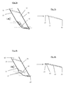
Figures 3a and 3b , features of the flow of fluid around afluidfoil 53 without deflected regions is explained. In use fluid approaches aleading edge 55 of the fluidfoil, passes the leadingedge 55 and travels over or under amain body 57 of thefluidfoil 53 before passing a trailingedge 59. The leadingedge 55 creates an adverse pressure gradient encountered by the fluid flowing towards it. This pressure gradient is stronger when thefluidfoil 53 is at higher angles of attack. The fluid flow approaching the leadingedge 55 will separate at the point where its momentum is insufficient to overcome the adverse pressure gradient. The further the fluid flow is from the leadingedge 55 at separation, the greater the size of thevortices 61 that will be produced by thefluidfoil 53. - Turning now to
Figures 4a and 4b , afluidfoil 63 is provided that is similar tofluidfoil 53. Like reference numerals for like features are used. The difference between the two fluidfoils 53 and 63 is the additional provision influidfoil 63 of aleading edge zone 65 having a deflectedregion 67 which locally reduces the angle of attack of thefluidfoil 63. Consequently fluid that is incident on the deflectedregion 67 has a higher momentum and therefore tends to separate closer to the leadingedge 55. Furthermore the higher momentum fluid tends to entrain surrounding fluid and increase its momentum even in fluid incident on other parts of the leadingedge 55 and leadingedge zone 65. The deflectedregions 67 therefore reduce the size of the vortices/wakes 61 produced by thefluidfoil 63, consequently reducing the noise it produces. Further the deflected region acts like an aerodynamic fence, partially blocking spanwise flow of fluid and therefore reducing fluidfoil tip vortices 69 (which are inefficient and may add to noise production especially where ingested by a downstream rotor). - It will be understood that the invention is not limited to the embodiments above-described and various modifications and improvements can be made without departing from the various concepts described herein. Any of the features may be employed separately or in combination with any other features and the invention extends to and includes all combinations and sub-combinations of one or more features described herein in any form of fluidfoil or gas turbine engine.
Claims (15)
- A fluidfoil comprising a leading edge and a leading edge zone behind the leading edge extending spanwise over the full span of the fluidfoil, where the leading edge zone comprises one or more deflected regions which locally reduce the angle of attack of the fluidfoil.
- A fluidfoil according to claim 1 where the deflected region comprises a local modification to the surface contouring of the leading edge zone.
- A fluidfoil according to claim 1 or claim 2 where the deflected region comprises a portion of the leading edge zone angled further towards the pressure surface of the fluidfoil than non-deflected regions of the leading edge zone which extend spanwise to either side and/or between each deflected region.
- A fluidfoil according to claim 3 where the fluidfoil has a consistent angle of attack in the non-deflected regions.
- A fluidfoil according to any preceding claim where there is no local chordwise extension of the leading edge associated with the deflected region.
- A fluidfoil according to any preceding claim where there is no local chordwise retraction of the leading edge associated with the deflected region.
- A fluidfoil according to any preceding claim where the extent of the deflected region decreases from the leading edge through the leading edge zone.
- A fluidfoil according to any preceding claim where the deflected region blends into a main body of the fluidfoil extending behind the leading edge zone and disappears.
- A fluidfoil according to claim 8 where the depth of the deflected region tapers in a chordwise direction from a maximum at the leading edge so as to blend with the main body of the fluidfoil.
- A fluidfoil according to claim 8 or claim 9 where the spanwise width of the deflected region decreases in a chordwise direction from a maximum at the leading edge, through the leading edge zone, to no spanwise width at the interface of the leading edge zone with the main body.
- A fluidfoil according to claim 3, claim 4 or any of claims 5 to 10 when dependent through to claim 3 where the depth of the deflected region tapers in one or both spanwise directions so as to blend with the respective non-deflected region of the leading edge zone.
- A fluidfoil according to any preceding claim where at least one deflected region is provided nearer to a tip than a root of the fluidfoil.
- A fluidfoil according to any preceding claim where the fluidfoil is an open-rotor blade.
- A gas turbine engine provided with one or more fluidfoils in accordance with any of claims 1 to 13.
- A gas turbine engine according to claim 14 utilising an open rotor configuration comprising a contra-rotating pair of rotors with at least one open rotor blade of the front-most rotor corresponding to the fluidfoil of any of claims 1 to 13.
Applications Claiming Priority (1)
| Application Number | Priority Date | Filing Date | Title |
|---|---|---|---|
| GBGB1301329.7A GB201301329D0 (en) | 2013-01-25 | 2013-01-25 | Fluidfoil |
Publications (3)
| Publication Number | Publication Date |
|---|---|
| EP2759471A2 true EP2759471A2 (en) | 2014-07-30 |
| EP2759471A3 EP2759471A3 (en) | 2018-01-03 |
| EP2759471B1 EP2759471B1 (en) | 2019-09-11 |
Family
ID=47843854
Family Applications (1)
| Application Number | Title | Priority Date | Filing Date |
|---|---|---|---|
| EP13196929.7A Active EP2759471B1 (en) | 2013-01-25 | 2013-12-12 | Fluidfoil |
Country Status (3)
| Country | Link |
|---|---|
| US (1) | US10113431B2 (en) |
| EP (1) | EP2759471B1 (en) |
| GB (1) | GB201301329D0 (en) |
Cited By (1)
| Publication number | Priority date | Publication date | Assignee | Title |
|---|---|---|---|---|
| EP3643877A1 (en) | 2018-10-22 | 2020-04-29 | Rolls-Royce plc | Ducted propulsor with airfoils having a leading edge with a deflected region |
Families Citing this family (4)
| Publication number | Priority date | Publication date | Assignee | Title |
|---|---|---|---|---|
| DE102022100315A1 (en) | 2022-01-07 | 2023-07-13 | MTU Aero Engines AG | Blade, in particular moving blade or guide blade, with an asymmetrical leading edge profile for a gas turbine |
| US12378887B2 (en) | 2022-11-28 | 2025-08-05 | General Electric Company | Airfoil assembly |
| US12618329B2 (en) | 2023-03-30 | 2026-05-05 | General Electric Company | Unducted airfoil assembly |
| US12215596B2 (en) | 2023-06-30 | 2025-02-04 | General Electric Company | Unducted airfoil assembly |
Family Cites Families (12)
| Publication number | Priority date | Publication date | Assignee | Title |
|---|---|---|---|---|
| US1366635A (en) | 1919-03-31 | 1921-01-25 | Edward P Conway | Propeller |
| US2800291A (en) * | 1950-10-24 | 1957-07-23 | Stephens Arthur Veryan | Solid boundary surface for contact with a relatively moving fluid medium |
| US4886421A (en) | 1984-01-09 | 1989-12-12 | Wind Feather, United Science Asc. | Wind turbine air foil |
| FR2609275B1 (en) | 1987-01-07 | 1989-03-31 | Riout Roland | PROFILED WING WITH CONTROLLED DEFORMATION AND APPLICATIONS IN PARTICULAR FOR FLYING WING AIRCRAFT |
| DE9013099U1 (en) * | 1990-09-14 | 1991-11-07 | Moser, Josef, 8058 Pretzen | rotor |
| FR2938502B1 (en) * | 2008-11-14 | 2010-12-10 | Snecma | TURBOMACHINE COMPRISING A NON-CARNEY PROPELLER EQUIPPED WITH AIR GUIDING MEANS |
| US20100329879A1 (en) | 2009-06-03 | 2010-12-30 | Presz Jr Walter M | Wind turbine blades with mixer lobes |
| EP2270312A1 (en) | 2009-07-01 | 2011-01-05 | PEM-Energy Oy | Aero- or hydrodynamic construction |
| US8573541B2 (en) | 2010-09-13 | 2013-11-05 | John Sullivan | Wavy airfoil |
| US20130224037A1 (en) * | 2011-09-13 | 2013-08-29 | Dennis Simpson | Compound airfoil |
| US9249666B2 (en) * | 2011-12-22 | 2016-02-02 | General Electric Company | Airfoils for wake desensitization and method for fabricating same |
| US9340277B2 (en) * | 2012-02-29 | 2016-05-17 | General Electric Company | Airfoils for use in rotary machines |
-
2013
- 2013-01-25 GB GBGB1301329.7A patent/GB201301329D0/en not_active Ceased
- 2013-12-12 US US14/104,607 patent/US10113431B2/en active Active
- 2013-12-12 EP EP13196929.7A patent/EP2759471B1/en active Active
Cited By (1)
| Publication number | Priority date | Publication date | Assignee | Title |
|---|---|---|---|---|
| EP3643877A1 (en) | 2018-10-22 | 2020-04-29 | Rolls-Royce plc | Ducted propulsor with airfoils having a leading edge with a deflected region |
Also Published As
| Publication number | Publication date |
|---|---|
| US10113431B2 (en) | 2018-10-30 |
| US20140212287A1 (en) | 2014-07-31 |
| EP2759471B1 (en) | 2019-09-11 |
| EP2759471A3 (en) | 2018-01-03 |
| GB201301329D0 (en) | 2013-03-06 |
Similar Documents
| Publication | Publication Date | Title |
|---|---|---|
| US10035582B2 (en) | Propeller blade for a turbomachine | |
| CN103287573B (en) | Aerofoil profile for rotating machinery | |
| AU2017261498A1 (en) | Improved wing configuration | |
| EP2287072A2 (en) | Fluidfoil tip vortex disruption | |
| US20150344127A1 (en) | Aeroelastically tailored propellers for noise reduction and improved efficiency in a turbomachine | |
| EP3027894B1 (en) | Rotor blade for a wind turbine, and wind turbine field | |
| US20160177914A1 (en) | Rotor blade with vortex generators | |
| EP3643877A1 (en) | Ducted propulsor with airfoils having a leading edge with a deflected region | |
| US10690112B2 (en) | Fluid turbine rotor blade with winglet design | |
| US10113431B2 (en) | Fluidfoil | |
| EP2685065A2 (en) | A gas turbine engine | |
| US8936435B2 (en) | System and method for root loss reduction in wind turbine blades | |
| US20180298912A1 (en) | Compressor blades and/or vanes | |
| US12352235B2 (en) | Wind turbine blades and wind turbine systems that include a co-flow jet | |
| US20140234112A1 (en) | Rotor blade | |
| EP2586973B1 (en) | Blade for a gas turbine engine | |
| EP2921401B1 (en) | Fluidfoil fence | |
| EP3717769A1 (en) | Wind turbine blade | |
| US12305611B2 (en) | Rotor blade of a wind turbine and corresponding wind turbine | |
| RU2004124502A (en) | AIR SCREW VANE, TURBOCHARGER, AIRCRAFT ROTARY wind turbine |
Legal Events
| Date | Code | Title | Description |
|---|---|---|---|
| PUAI | Public reference made under article 153(3) epc to a published international application that has entered the european phase |
Free format text: ORIGINAL CODE: 0009012 |
|
| 17P | Request for examination filed |
Effective date: 20131212 |
|
| AK | Designated contracting states |
Kind code of ref document: A2 Designated state(s): AL AT BE BG CH CY CZ DE DK EE ES FI FR GB GR HR HU IE IS IT LI LT LU LV MC MK MT NL NO PL PT RO RS SE SI SK SM TR |
|
| AX | Request for extension of the european patent |
Extension state: BA ME |
|
| RAP1 | Party data changed (applicant data changed or rights of an application transferred) |
Owner name: ROLLS-ROYCE PLC |
|
| PUAL | Search report despatched |
Free format text: ORIGINAL CODE: 0009013 |
|
| AK | Designated contracting states |
Kind code of ref document: A3 Designated state(s): AL AT BE BG CH CY CZ DE DK EE ES FI FR GB GR HR HU IE IS IT LI LT LU LV MC MK MT NL NO PL PT RO RS SE SI SK SM TR |
|
| AX | Request for extension of the european patent |
Extension state: BA ME |
|
| RIC1 | Information provided on ipc code assigned before grant |
Ipc: B64C 11/18 20060101ALI20171124BHEP Ipc: B64D 27/00 20060101ALI20171124BHEP Ipc: F01D 5/14 20060101ALI20171124BHEP Ipc: B64C 3/38 20060101AFI20171124BHEP |
|
| STAA | Information on the status of an ep patent application or granted ep patent |
Free format text: STATUS: REQUEST FOR EXAMINATION WAS MADE |
|
| R17P | Request for examination filed (corrected) |
Effective date: 20180523 |
|
| RBV | Designated contracting states (corrected) |
Designated state(s): AL AT BE BG CH CY CZ DE DK EE ES FI FR GB GR HR HU IE IS IT LI LT LU LV MC MK MT NL NO PL PT RO RS SE SI SK SM TR |
|
| STAA | Information on the status of an ep patent application or granted ep patent |
Free format text: STATUS: EXAMINATION IS IN PROGRESS |
|
| 17Q | First examination report despatched |
Effective date: 20181002 |
|
| GRAP | Despatch of communication of intention to grant a patent |
Free format text: ORIGINAL CODE: EPIDOSNIGR1 |
|
| STAA | Information on the status of an ep patent application or granted ep patent |
Free format text: STATUS: GRANT OF PATENT IS INTENDED |
|
| GRAS | Grant fee paid |
Free format text: ORIGINAL CODE: EPIDOSNIGR3 |
|
| GRAA | (expected) grant |
Free format text: ORIGINAL CODE: 0009210 |
|
| STAA | Information on the status of an ep patent application or granted ep patent |
Free format text: STATUS: THE PATENT HAS BEEN GRANTED |
|
| INTG | Intention to grant announced |
Effective date: 20190716 |
|
| AK | Designated contracting states |
Kind code of ref document: B1 Designated state(s): AL AT BE BG CH CY CZ DE DK EE ES FI FR GB GR HR HU IE IS IT LI LT LU LV MC MK MT NL NO PL PT RO RS SE SI SK SM TR |
|
| REG | Reference to a national code |
Ref country code: GB Ref legal event code: FG4D |
|
| REG | Reference to a national code |
Ref country code: CH Ref legal event code: EP |
|
| REG | Reference to a national code |
Ref country code: AT Ref legal event code: REF Ref document number: 1178121 Country of ref document: AT Kind code of ref document: T Effective date: 20190915 |
|
| REG | Reference to a national code |
Ref country code: DE Ref legal event code: R096 Ref document number: 602013060299 Country of ref document: DE Ref country code: IE Ref legal event code: FG4D |
|
| REG | Reference to a national code |
Ref country code: NL Ref legal event code: MP Effective date: 20190911 |
|
| REG | Reference to a national code |
Ref country code: LT Ref legal event code: MG4D |
|
| PG25 | Lapsed in a contracting state [announced via postgrant information from national office to epo] |
Ref country code: LT Free format text: LAPSE BECAUSE OF FAILURE TO SUBMIT A TRANSLATION OF THE DESCRIPTION OR TO PAY THE FEE WITHIN THE PRESCRIBED TIME-LIMIT Effective date: 20190911 Ref country code: HR Free format text: LAPSE BECAUSE OF FAILURE TO SUBMIT A TRANSLATION OF THE DESCRIPTION OR TO PAY THE FEE WITHIN THE PRESCRIBED TIME-LIMIT Effective date: 20190911 Ref country code: BG Free format text: LAPSE BECAUSE OF FAILURE TO SUBMIT A TRANSLATION OF THE DESCRIPTION OR TO PAY THE FEE WITHIN THE PRESCRIBED TIME-LIMIT Effective date: 20191211 Ref country code: SE Free format text: LAPSE BECAUSE OF FAILURE TO SUBMIT A TRANSLATION OF THE DESCRIPTION OR TO PAY THE FEE WITHIN THE PRESCRIBED TIME-LIMIT Effective date: 20190911 Ref country code: FI Free format text: LAPSE BECAUSE OF FAILURE TO SUBMIT A TRANSLATION OF THE DESCRIPTION OR TO PAY THE FEE WITHIN THE PRESCRIBED TIME-LIMIT Effective date: 20190911 Ref country code: NO Free format text: LAPSE BECAUSE OF FAILURE TO SUBMIT A TRANSLATION OF THE DESCRIPTION OR TO PAY THE FEE WITHIN THE PRESCRIBED TIME-LIMIT Effective date: 20191211 |
|
| RAP2 | Party data changed (patent owner data changed or rights of a patent transferred) |
Owner name: ROLLS-ROYCE PLC |
|
| PG25 | Lapsed in a contracting state [announced via postgrant information from national office to epo] |
Ref country code: ES Free format text: LAPSE BECAUSE OF FAILURE TO SUBMIT A TRANSLATION OF THE DESCRIPTION OR TO PAY THE FEE WITHIN THE PRESCRIBED TIME-LIMIT Effective date: 20190911 Ref country code: RS Free format text: LAPSE BECAUSE OF FAILURE TO SUBMIT A TRANSLATION OF THE DESCRIPTION OR TO PAY THE FEE WITHIN THE PRESCRIBED TIME-LIMIT Effective date: 20190911 Ref country code: AL Free format text: LAPSE BECAUSE OF FAILURE TO SUBMIT A TRANSLATION OF THE DESCRIPTION OR TO PAY THE FEE WITHIN THE PRESCRIBED TIME-LIMIT Effective date: 20190911 Ref country code: GR Free format text: LAPSE BECAUSE OF FAILURE TO SUBMIT A TRANSLATION OF THE DESCRIPTION OR TO PAY THE FEE WITHIN THE PRESCRIBED TIME-LIMIT Effective date: 20191212 Ref country code: LV Free format text: LAPSE BECAUSE OF FAILURE TO SUBMIT A TRANSLATION OF THE DESCRIPTION OR TO PAY THE FEE WITHIN THE PRESCRIBED TIME-LIMIT Effective date: 20190911 |
|
| REG | Reference to a national code |
Ref country code: AT Ref legal event code: MK05 Ref document number: 1178121 Country of ref document: AT Kind code of ref document: T Effective date: 20190911 |
|
| PG25 | Lapsed in a contracting state [announced via postgrant information from national office to epo] |
Ref country code: RO Free format text: LAPSE BECAUSE OF FAILURE TO SUBMIT A TRANSLATION OF THE DESCRIPTION OR TO PAY THE FEE WITHIN THE PRESCRIBED TIME-LIMIT Effective date: 20190911 Ref country code: IT Free format text: LAPSE BECAUSE OF FAILURE TO SUBMIT A TRANSLATION OF THE DESCRIPTION OR TO PAY THE FEE WITHIN THE PRESCRIBED TIME-LIMIT Effective date: 20190911 Ref country code: EE Free format text: LAPSE BECAUSE OF FAILURE TO SUBMIT A TRANSLATION OF THE DESCRIPTION OR TO PAY THE FEE WITHIN THE PRESCRIBED TIME-LIMIT Effective date: 20190911 Ref country code: AT Free format text: LAPSE BECAUSE OF FAILURE TO SUBMIT A TRANSLATION OF THE DESCRIPTION OR TO PAY THE FEE WITHIN THE PRESCRIBED TIME-LIMIT Effective date: 20190911 Ref country code: NL Free format text: LAPSE BECAUSE OF FAILURE TO SUBMIT A TRANSLATION OF THE DESCRIPTION OR TO PAY THE FEE WITHIN THE PRESCRIBED TIME-LIMIT Effective date: 20190911 Ref country code: PT Free format text: LAPSE BECAUSE OF FAILURE TO SUBMIT A TRANSLATION OF THE DESCRIPTION OR TO PAY THE FEE WITHIN THE PRESCRIBED TIME-LIMIT Effective date: 20200113 Ref country code: PL Free format text: LAPSE BECAUSE OF FAILURE TO SUBMIT A TRANSLATION OF THE DESCRIPTION OR TO PAY THE FEE WITHIN THE PRESCRIBED TIME-LIMIT Effective date: 20190911 |
|
| PG25 | Lapsed in a contracting state [announced via postgrant information from national office to epo] |
Ref country code: SK Free format text: LAPSE BECAUSE OF FAILURE TO SUBMIT A TRANSLATION OF THE DESCRIPTION OR TO PAY THE FEE WITHIN THE PRESCRIBED TIME-LIMIT Effective date: 20190911 Ref country code: IS Free format text: LAPSE BECAUSE OF FAILURE TO SUBMIT A TRANSLATION OF THE DESCRIPTION OR TO PAY THE FEE WITHIN THE PRESCRIBED TIME-LIMIT Effective date: 20200224 Ref country code: SM Free format text: LAPSE BECAUSE OF FAILURE TO SUBMIT A TRANSLATION OF THE DESCRIPTION OR TO PAY THE FEE WITHIN THE PRESCRIBED TIME-LIMIT Effective date: 20190911 Ref country code: CZ Free format text: LAPSE BECAUSE OF FAILURE TO SUBMIT A TRANSLATION OF THE DESCRIPTION OR TO PAY THE FEE WITHIN THE PRESCRIBED TIME-LIMIT Effective date: 20190911 |
|
| REG | Reference to a national code |
Ref country code: DE Ref legal event code: R097 Ref document number: 602013060299 Country of ref document: DE |
|
| PLBE | No opposition filed within time limit |
Free format text: ORIGINAL CODE: 0009261 |
|
| STAA | Information on the status of an ep patent application or granted ep patent |
Free format text: STATUS: NO OPPOSITION FILED WITHIN TIME LIMIT |
|
| PG2D | Information on lapse in contracting state deleted |
Ref country code: IS |
|
| PG25 | Lapsed in a contracting state [announced via postgrant information from national office to epo] |
Ref country code: DK Free format text: LAPSE BECAUSE OF FAILURE TO SUBMIT A TRANSLATION OF THE DESCRIPTION OR TO PAY THE FEE WITHIN THE PRESCRIBED TIME-LIMIT Effective date: 20190911 Ref country code: IS Free format text: LAPSE BECAUSE OF FAILURE TO SUBMIT A TRANSLATION OF THE DESCRIPTION OR TO PAY THE FEE WITHIN THE PRESCRIBED TIME-LIMIT Effective date: 20200112 |
|
| REG | Reference to a national code |
Ref country code: CH Ref legal event code: PL |
|
| 26N | No opposition filed |
Effective date: 20200615 |
|
| REG | Reference to a national code |
Ref country code: BE Ref legal event code: MM Effective date: 20191231 |
|
| PG25 | Lapsed in a contracting state [announced via postgrant information from national office to epo] |
Ref country code: MC Free format text: LAPSE BECAUSE OF FAILURE TO SUBMIT A TRANSLATION OF THE DESCRIPTION OR TO PAY THE FEE WITHIN THE PRESCRIBED TIME-LIMIT Effective date: 20190911 Ref country code: SI Free format text: LAPSE BECAUSE OF FAILURE TO SUBMIT A TRANSLATION OF THE DESCRIPTION OR TO PAY THE FEE WITHIN THE PRESCRIBED TIME-LIMIT Effective date: 20190911 |
|
| PG25 | Lapsed in a contracting state [announced via postgrant information from national office to epo] |
Ref country code: IE Free format text: LAPSE BECAUSE OF NON-PAYMENT OF DUE FEES Effective date: 20191212 Ref country code: LU Free format text: LAPSE BECAUSE OF NON-PAYMENT OF DUE FEES Effective date: 20191212 |
|
| PG25 | Lapsed in a contracting state [announced via postgrant information from national office to epo] |
Ref country code: BE Free format text: LAPSE BECAUSE OF NON-PAYMENT OF DUE FEES Effective date: 20191231 Ref country code: CH Free format text: LAPSE BECAUSE OF NON-PAYMENT OF DUE FEES Effective date: 20191231 Ref country code: LI Free format text: LAPSE BECAUSE OF NON-PAYMENT OF DUE FEES Effective date: 20191231 |
|
| PG25 | Lapsed in a contracting state [announced via postgrant information from national office to epo] |
Ref country code: CY Free format text: LAPSE BECAUSE OF FAILURE TO SUBMIT A TRANSLATION OF THE DESCRIPTION OR TO PAY THE FEE WITHIN THE PRESCRIBED TIME-LIMIT Effective date: 20190911 |
|
| PG25 | Lapsed in a contracting state [announced via postgrant information from national office to epo] |
Ref country code: HU Free format text: LAPSE BECAUSE OF FAILURE TO SUBMIT A TRANSLATION OF THE DESCRIPTION OR TO PAY THE FEE WITHIN THE PRESCRIBED TIME-LIMIT; INVALID AB INITIO Effective date: 20131212 Ref country code: MT Free format text: LAPSE BECAUSE OF FAILURE TO SUBMIT A TRANSLATION OF THE DESCRIPTION OR TO PAY THE FEE WITHIN THE PRESCRIBED TIME-LIMIT Effective date: 20190911 |
|
| PG25 | Lapsed in a contracting state [announced via postgrant information from national office to epo] |
Ref country code: TR Free format text: LAPSE BECAUSE OF FAILURE TO SUBMIT A TRANSLATION OF THE DESCRIPTION OR TO PAY THE FEE WITHIN THE PRESCRIBED TIME-LIMIT Effective date: 20190911 |
|
| PG25 | Lapsed in a contracting state [announced via postgrant information from national office to epo] |
Ref country code: MK Free format text: LAPSE BECAUSE OF FAILURE TO SUBMIT A TRANSLATION OF THE DESCRIPTION OR TO PAY THE FEE WITHIN THE PRESCRIBED TIME-LIMIT Effective date: 20190911 |
|
| P01 | Opt-out of the competence of the unified patent court (upc) registered |
Effective date: 20230528 |
|
| PGFP | Annual fee paid to national office [announced via postgrant information from national office to epo] |
Ref country code: GB Payment date: 20251223 Year of fee payment: 13 |
|
| PGFP | Annual fee paid to national office [announced via postgrant information from national office to epo] |
Ref country code: FR Payment date: 20251230 Year of fee payment: 13 |
|
| PGFP | Annual fee paid to national office [announced via postgrant information from national office to epo] |
Ref country code: DE Payment date: 20251229 Year of fee payment: 13 |