EP2759253A1 - Image processing apparatus - Google Patents
Image processing apparatus Download PDFInfo
- Publication number
- EP2759253A1 EP2759253A1 EP14152050.2A EP14152050A EP2759253A1 EP 2759253 A1 EP2759253 A1 EP 2759253A1 EP 14152050 A EP14152050 A EP 14152050A EP 2759253 A1 EP2759253 A1 EP 2759253A1
- Authority
- EP
- European Patent Office
- Prior art keywords
- reference line
- cross sectional
- image
- sectional position
- setting
- Prior art date
- Legal status (The legal status is an assumption and is not a legal conclusion. Google has not performed a legal analysis and makes no representation as to the accuracy of the status listed.)
- Granted
Links
- 0 CCC(CCC1)C(*)(CC2)CC12C=C=CC(*1CC1)=* Chemical compound CCC(CCC1)C(*)(CC2)CC12C=C=CC(*1CC1)=* 0.000 description 1
Images





Classifications
-
- A—HUMAN NECESSITIES
- A61—MEDICAL OR VETERINARY SCIENCE; HYGIENE
- A61B—DIAGNOSIS; SURGERY; IDENTIFICATION
- A61B3/00—Apparatus for testing the eyes; Instruments for examining the eyes
- A61B3/10—Objective types, i.e. instruments for examining the eyes independent of the patients' perceptions or reactions
- A61B3/102—Objective types, i.e. instruments for examining the eyes independent of the patients' perceptions or reactions for optical coherence tomography [OCT]
-
- A—HUMAN NECESSITIES
- A61—MEDICAL OR VETERINARY SCIENCE; HYGIENE
- A61B—DIAGNOSIS; SURGERY; IDENTIFICATION
- A61B3/00—Apparatus for testing the eyes; Instruments for examining the eyes
- A61B3/10—Objective types, i.e. instruments for examining the eyes independent of the patients' perceptions or reactions
- A61B3/1025—Objective types, i.e. instruments for examining the eyes independent of the patients' perceptions or reactions for confocal scanning
-
- A—HUMAN NECESSITIES
- A61—MEDICAL OR VETERINARY SCIENCE; HYGIENE
- A61B—DIAGNOSIS; SURGERY; IDENTIFICATION
- A61B3/00—Apparatus for testing the eyes; Instruments for examining the eyes
- A61B3/10—Objective types, i.e. instruments for examining the eyes independent of the patients' perceptions or reactions
- A61B3/14—Arrangements specially adapted for eye photography
Definitions
- the present disclosure relates to an image processing technique which processes a tomographic image of an eye to be examined.
- OCT optical coherent tomography
- the examiner inputs an instruction for designating a capturing position of a tomographic image (that is, a cross sectional position at which measurement light is scanned) to the ophthalmologic photographing apparatus while observing, with a monitor, moving images obtained by photographing a front side of the eye.
- the ophthalmologic photographing apparatus scans by the measurement light a cross sectional position designated by the examiner and generates a tomographic image based on a reflected light of the measurement light.
- An object of the present disclosure is to provide an image processing apparatus capable of appropriately setting a cross sectional position for acquiring or generating a tomographic image of tissue of an eye, to have a predetermined angle relative to a specific direction of the tissue.
- An aspect of the present disclosure provides the following arrangements:
- an axis direction of an eye E to be examined is set to a Z direction
- a horizontal direction is set to an X direction
- a vertical direction is set to a Y direction
- a surface direction of the fundus may be considered to be an XY direction.
- the ophthalmologic photographing apparatus 10 includes an OCT optical system 100, an observation optical system 200, a fixation target projection unit 300, and a controller 70.
- the OCT optical system 100 is an interference optical system which acquires a tomographic image of tissue (for example, the fundus Ef) of the eye E, and has a configuration of optical coherence tomography (OCT).
- the OCT optical system 100 includes a measurement light source 102, a coupler (light splitter) 104, a measurement optical system 106, a reference optical system 110, and a detector (light receiving element) 120.
- the measurement light source 102 emits light for acquiring a tomographic image.
- the coupler 104 splits the light emitted from the measurement light source 102 into measurement light (sample light) and reference light.
- the coupler 104 combines measurement light which is reflected by the fundus Ef and reference light generated by the reference optical system 110 and allows the detector 120 to receive the combined light.
- the measurement optical system 106 guides the measurement light split by the coupler 104 to the fundus Ef of the eye E.
- the measurement optical system 106 includes a light scanner 108 at a position which is substantially conjugate to the pupil.
- the measurement optical system 106 drives the light scanner 108 by using a driving mechanism 50 so as to scan the measurement light on the fundus Ef in a two-dimensional direction.
- a capturing position of a tomographic image on the fundus Ef is determined.
- a cross sectional position of the measurement light which is scanned by the light scanner 108 becomes a capturing position of a tomographic image.
- a variety of devices which deflect light such as a reflection mirror (a galvano mirror, a polygon mirror, or a resonant scanner) and an acoustic optical modulator (AOM) may be used as the light scanner 108.
- a reflection mirror a galvano mirror, a polygon mirror, or a resonant scanner
- AOM acoustic optical modulator
- the reference optical system 110 generates reference light. As described above, the reference light is combined with the reflected light of the measurement light from the fundus Ef.
- the reference optical system 110 may be of a Michelson type and of a Mach-Zehnder type. In the present embodiment, the reference optical system 110 reflects the light guided by the coupler 104 by using a reflection optical system which includes a reference mirror and the like. The reflected light is returned to the coupler 104 again as reference light.
- a configuration of the reference optical system 110 may be changed. For example, the reference optical system 110 may not reflect the light guided by the coupler 104 but may transmit the light through the detector 120 by using a transmission optical system such as an optical fiber.
- the OCT optical system 100 changes an optical path length difference between the measurement light and the reference light.
- the OCT optical system 100 changes the optical path length difference by moving an optical member (specifically, the reference mirror) included in the reference optical system 110 in an optical axis direction.
- a configuration for changing an optical path length difference may be disposed in a measurement optical path of the measurement optical system 106.
- the detector 120 detects an interference state of the measurement light and the reference light.
- a spectral intensity of interference light is detected by the detector 120, and a depth profile (an A scan signal) in a predetermined range is acquired through Fourier transform of the spectral intensity data.
- the ophthalmologic photographing apparatus 10 may employ a variety of OCT.
- the ophthalmologic photographing apparatus 10 may employ any one of spectral-domain OCT (SD-OCT), swept-source OCT (SS-OCT), and time-domain OCT (TD-OCT).
- the observation optical system 200 is provided so as to acquire a front image of tissue (the fundus Ef in the present embodiment) of the eye E.
- the observation optical system 200 according to the present embodiment has a configuration of a so-called scanning laser ophthalmoscope (SLO). More specifically, the observation optical system 200 includes a light scanner and a light receiving element (not illustrated).
- the light scanner scans measurement light (for example, infrared light) emitted from the light source on the fundus Ef in a two-dimensional direction.
- the light receiving element receives reflected light of the measurement light from the fundus Ef, via a confocal aperture disposed at a position which is substantially conjugate to the fundus Ef.
- the observation optical system 200 may employ a configuration (a so-called fundus camera type configuration) of acquiring a front image such as a still image and a moving image by widely applying infrared light or the like. Further, the OCT optical system 100 may be also used as the observation optical system 200. In other words, the ophthalmologic photographing apparatus 10 may acquire a front image of the tissue by using data acquired by the OCT optical system 100, the data being used to generate a tomographic image.
- a configuration a so-called fundus camera type configuration
- the OCT optical system 100 may be also used as the observation optical system 200.
- the ophthalmologic photographing apparatus 10 may acquire a front image of the tissue by using data acquired by the OCT optical system 100, the data being used to generate a tomographic image.
- the ophthalmologic photographing apparatus 10 may acquire a front image by using an integrated image of a three-dimensional tomographic image in a depth direction, an integrated value of spectrum data at respective positions in the XY direction, luminance data at respective positions in the XY direction in a specific depth direction, a retinal surface image, and the like.
- the controller 70 described later may perform alignment (matching) between a front image acquired by the observation optical system 200 and an image (for example, a two-dimensional image from a front direction, obtained by integrating data of a three-dimensional image in the depth direction) acquired by the OCT optical system 100.
- the controller 70 may correlate the three-dimensional image with the front image so as to perform processes such as display and analysis on the correlated images.
- the fixation target projection unit 300 is provided so as to induce a visual line direction of the eye E.
- the fixation target projection unit 300 includes a visible light source which generates visible light, and changes a presentation position of an index shown by the visible light source.
- the visual line direction of the eye E is changed, and thus a photographing part of the fundus Ef is changed.
- a fixation target is presented from the same direction as a photographing optical axis, a central part of the fundus Ef becomes a photographing part.
- an upper part of the fundus Ef becomes a photographing part.
- the fixation target projection unit 300 may employ various configurations.
- a configuration may be employed in which a fixation position is adjusted by turning-on positions of LEDs which are arranged in a matrix.
- a configuration may be employed in which visible light is scanned using a light scanner.
- the fixation target projection unit 300 may be of an inner fixation lighting type in which a fixation target is displayed inside the device, and may be of an outer fixation lighting type in which a fixation target is displayed outside the device.
- the controller 70 includes a CPU (processor), a RAM, a ROM, and the like.
- the CPU of the controller 70 controls the ophthalmologic photographing apparatus 10.
- the RAM temporarily stores various information.
- Various programs, initial values, and the like for controlling an operation of the ophthalmologic photographing apparatus 10 are stored in the ROM of the controller 70.
- the controller 70 is electrically connected to a nonvolatile memory 72, an operation portion 74, a display portion 75, and the like.
- the nonvolatile memory 72 is a non-transitive storage medium which can hold storage content even if the supply of power is cut off.
- a hard disk drive, a flash ROM, a USB memory attachable to and detachable from the ophthalmologic photographing apparatus 10, and the like may be used as the nonvolatile memory 72.
- a photographing control program for controlling capturing of a front image and a tomographic image, performed by the ophthalmologic photographing apparatus 10, is stored in the nonvolatile memory 72.
- a two-dimensional tomographic image, a three-dimensional image, and a front image, which are captured, and various information regarding photographing such as information regarding a capturing position of a tomographic image, are stored in the nonvolatile memory 72.
- Various operation instructions are input to the operation portion 74 by an examiner.
- the operation portion 74 outputs a signal corresponding to an input operation instruction to the controller 70.
- At least one of, for example, a mouse, a joystick, a keyboard, a touch panel, and the like may be used in the operation portion 74.
- the display portion 75 may be a display mounted in a main body of the ophthalmologic photographing apparatus 10, and may be a display connected to the main body.
- a display of a personal computer hereinafter, referred to as a "PC" may be used.
- a plurality of displays may be used together.
- Various images including a tomographic image and a front image captured by the ophthalmologic photographing apparatus 10 are displayed on the display portion 75.
- the controller 70 may be constituted by a plurality of controllers (that is, a plurality of processors).
- the controller 70 of the ophthalmologic photographing apparatus 10 may be constituted by a setting controller provided in a PC and an operation controller which controls an operation of the OCT optical system 100 or the like.
- the setting controller of the PC may set a capturing position of a tomographic image on the basis of an operation of the operation portion connected to the PC, and may instruct the operation controller to perform the setting content.
- the operation controller may control a photographing operation of each constituent element of the ophthalmologic photographing apparatus 10 on the basis of the instruction from the setting controller.
- a process of generating (acquiring) an image on the basis of a light receiving signal may be performed by either of the operation controller and the setting controller.
- the ophthalmologic photographing apparatus 10 can appropriately set an acquisition position (that is, a cross sectional position of measurement light) of a tomographic image to have a predetermined angle relative to a specific direction of tissue (for example, the fundus Ef) of the eye E.
- a specific direction of tissue for example, the fundus Ef
- the cross sectional position is set to have the predetermined angle relative to the specific direction of the tissue, and thus a tomographic image useful for diagnosis is obtained.
- the fundus Ef is divided using a line which passes through a papilla 7 and a macula 8 (refer to Fig.
- a cross sectional position is made to intersect the line passing through the papilla 7 and the macula 8
- an examiner can easily judge symmetry of tissue in which the line serves as a boundary, from a tomographic image.
- a cross sectional position is made to intersect a blood vessel 9 (refer to Fig. 2 )
- the examiner can easily judge a blood vessel diameter, a blood flow rate, a bloodstream, and the like from a tomographic image.
- Information useful to the examiner may be obtained by setting an angle of a cross sectional position depending on a lesion part. Further, useful information may be obtained by setting a cross sectional position parallel to a direction of tissue.
- the ophthalmologic photographing apparatus 10 sets a reference line 20 which is used as a reference for setting a cross sectional position 30, on a front image 2.
- the cross sectional position 30 having a predetermined angle as an angle relative to the set reference line 20 is set.
- Measurement light is scanned on tissue corresponding to the set cross sectional position 30, thereby obtaining a fundus image 5. Therefore, the ophthalmologic photographing apparatus 10 can appropriately set the cross sectional position 30 having a predetermined angle relative to a specific direction of the tissue. As a result, it is possible to easily obtain the tomographic image 5 useful for diagnosis.
- the ophthalmologic photographing apparatus 10 can execute a "designated part diagnosis mode", a "blood vessel diagnosis mode”, and a "normal mode".
- the linear reference line 20 is set at a part designated by the examiner, and an angle of the cross sectional position 30 is set on the basis of the set reference line 20. Therefore, the examiner just sets the reference line 20 in a desired direction at a desired part, and thus can easily set the cross sectional position 30 having a suitable angle.
- the reference line 20 is set along the blood vessel 9, and an angle of the cross sectional position 30 is set on the basis of the set reference line 20. Therefore, according to the "blood vessel diagnosis mode", the examiner can easily make a diagnosis related to the blood vessel 9.
- the cross sectional position 30 is set without setting the reference line 20.
- a description of the "normal mode” will be made briefly.
- a mode setting process performed by the controller 70 of the ophthalmologic photographing apparatus 10 will be described.
- any one of the "designated part diagnosis mode", the "blood vessel diagnosis mode”, and the "normal mode” is selected by the examiner.
- a photographing condition for executing a selected mode is set on the basis of an instruction from the examiner.
- the controller 70 performs the mode setting process illustrated in Fig. 3 according to the photographing control program stored in the nonvolatile memory 72.
- a selection screen (not illustrated) which allows the examiner to select a photographing mode is displayed on the display portion 75.
- the examiner operates the operation portion 74 (for example, a touch panel, a mouse, or the like) so as to input a mode selection instruction.
- the selected mode is the "designated part diagnosis mode” (S1: YES)
- a designated part photographing condition setting process is performed (S2)
- the mode setting process finishes.
- the selected mode is not the "designated part diagnosis mode” (S1: NO) but the "blood vessel diagnosis mode” (S4: YES)
- a blood vessel photographing condition setting process is performed (S5), and the mode setting process finishes.
- the "normal mode” is selected (S4. NO)
- a normal photographing condition setting process is performed (S6), and the process finishes.
- a designated part photographing condition setting screen 15 is displayed on the display portion 75.
- a reference line setting method selection item, a relative angle selection item, a cross sectional position setting method selection item, and a reference line photographing selection item are provided.
- the examiner operates the operation portion 74 so as to select any one of a plurality of options in each item.
- the controller 70 sets a photographing condition on the basis of the selection performed by the examiner.
- the reference line setting method is a method of setting the reference line 20 on the front image 2.
- the reference line setting method according to the present embodiment includes options such as "papilla and macula automatic setting”, “direct manual setting”, and “passing point manual setting”.
- the option "papilla and macula automatic setting” the reference line 20 passing through the papilla 7 and the macula 8 is automatically set.
- the examiner may manually set the reference line 20 having a desired angle at a desired position by moving a reference index which is displayed on the front image 2 in a superimposition manner.
- the examiner may set the reference line 20 passing through two passing points by manually setting the two passing points on the front image 2.
- the relative angle is an angle of the cross sectional position 30 relative to the reference line 20.
- the examiner may select either of the options "perpendicular" and "arbitrary designation”. If the examiner selects the option "perpendicular”, the cross sectional position 30 perpendicular to the reference line 20 is set. If the examiner selects the option "arbitrary designation", a state in which an angle can be input occurs, and an input angle is set as the relative angle.
- the cross sectional position setting method is a method of setting the cross sectional position 30 on the basis of the reference line 20.
- any one of options such as “manual”, “number designation”, and “space designation” may be selected.
- the examiner may manually set a desired number of cross sectional positions 30 of which an angle relative to the reference line 20 is the relative angle, at desired positions.
- the option "number designation” when the examiner designates the number of cross sectional positions 30, the cross sectional positions 30 of the designated number are set with equal spaces therebetween.
- space designation a plurality of cross sectional positions are set between two end points on the reference line 20 with spaces therebetween designated by the examiner.
- the reference line photographing indicates whether or not the cross sectional position 30 is set on the reference line 20. If an option of "YES" is selected, the cross sectional position 30 is also set on the reference line 20 in addition to the cross sectional position 30 intersecting the reference line 20. If an option of "NO" is selected, the cross sectional position 30 along the reference line 20 is not set.
- a blood vessel photographing condition setting screen 16 is displayed on the display portion 75.
- a relative angle selection item, a cross sectional position setting method selection item, and a display method selection item are provided in the blood vessel photographing condition setting screen 16.
- the relative angle selection item and the cross sectional position setting method selection item are the same as in the designated part photographing condition setting screen 15 (refer to Fig. 4 ).
- the display method is a method of displaying a tomographic image of the blood vessel 9. The examiner may select either of display methods of "moving image" and "still image”.
- a designated part photographing process performed by the controller 70 will be described.
- the fundus Ef is photographed in the "designated part diagnosis mode".
- the controller 70 performs the designated part photographing process illustrated in Fig. 6 according to the photographing control program stored in the nonvolatile memory 72.
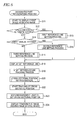
- the observation optical system 200 starts to capture a front image 2 of the fundus Ef so as to display moving images in real time on the display portion 75 (S11). If a reference line setting method selected by the examiner is the option "papilla and macula automatic setting" (S12: YES), a first reference line setting process is performed (S13), and the process proceeds to S18. If the option “direct manual setting” is selected (S12: NO, and S14: YES), a second reference line setting process is performed (S15), and the process proceeds to S 18. If the option "passing point manual setting” is selected (S14: NO), a third reference line setting process is performed (S16), and the process proceeds to S18.
- the latest captured still image of the front image 2 is acquired as a reference image and is stored in the RAM (S31).
- a well-known image process is performed on the reference image, and thus a position of the papilla 7 and a position of the macula 8 (refer to Fig. 11 ) are detected (S32).
- an algorithm for the image process any one of various algorithms such as edge detection and Hough conversion algorithms may be used.
- the linear reference line 20 which passes through both of the detected papilla 7 and macula 8 is set on the reference image (S33). The process returns to the designated part photographing process (refer to Fig. 6 ). Due to the above-described process, the reference line 20 which passes through the papilla 7 and the macula 8 is automatically set.
- a reference index which is used as an index for setting the reference line 20 is displayed on the front image 2 in a superimposition manner (S41).
- the reference index is displayed by the broken line in the same manner as in the display aspect of the reference line 20 illustrated in Fig. 2 .
- it is determined whether or not a drag operation of the reference index is started by the examiner (S42).
- the examiner operates the mouse of the operation portion 74 so as to move a pointer to the reference index, and drags the pointer so as to move the reference index.
- a method of moving the reference index may be changed. A standby state occurs until the drag operation is performed (S42: NO).
- the controller 70 rotates the reference index displayed on the front image 2 on the basis of a predetermined operation (for example, a right click operation of the mouse, a rotation operation of the wheel, an operation on the keyboard, and the like) on the operation portion 74.
- a predetermined operation for example, a right click operation of the mouse, a rotation operation of the wheel, an operation on the keyboard, and the like
- the front image 2 which is currently displayed as moving images is stopped as the latest still image (S44).
- the reference index is moved on the front image 2 which is a still image in response to an operation on the operation portion 74 (S45). Therefore, the examiner can easily set the reference line 20 on the still image without being influenced by involuntary eye movement or the like during fixation.
- the process in S45 is continuously performed until the drag operation is finished (S46: NO). If the drag operation is finished (S46: YES), the reference line 20 is set on the moved reference index (S48).
- the front image 2 which is currently displayed as a still image is converted into a moving image (S49), and the process returns to the designated part photographing process (refer to Fig.
- the linear reference line 20 is directly manually set by the examiner.
- the reference index may be moved to positions which pass through both of the papilla 7 and the macula 8.
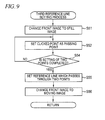
- the front image 2 which is currently displayed as a moving image is converted into the latest still image (S51).
- the examiner moves the pointer displayed on the front image 2 which is a still image with the mouse and performs a click operation, so as to designate positions of passing points of the reference line 20.
- the controller 70 sets points designated by the click operation as the passing points (S52).
- the process in S52 is repeatedly performed until setting of two passing points is completed (S54: NO). If the setting of two passing points is completed (S54: YES), the reference line 20 which passes through both passing points is set (S55).
- the front image 2 which is currently displayed as a still image is converted into a moving image (S56), and the process returns to the designated part photographing process (refer to Fig. 6 ). Due to the above-described process, the examiner just manually sets two passing points at desired positions on the front image 2, so as to set the reference line 20. For example, in a case where the examiner wishes to set the reference line 20 illustrated in Fig. 11 , a passing point may be set at each of the papilla 7 and the macula 8. In addition, the examiner can easily set the reference line 20 which crosses a lesion part or the like in a predetermined direction.
- the reference line tracking process is a process of causing a position of the reference line 20 to track a correct position on the front image 2 which is currently displayed as a moving image.
- positional deviation of the front image 2 that is, the latest front image 2 on which the reference line 20 has been set, relative to the front image 2 as a still image on which the reference line 20 was set, is detected through the above-described image process.
- Parameters of the detected positional deviation include a direction, a distance, and an angle.
- the controller 70 moves a position of the reference line 20 by a detected distance in a detected direction, and also rotates the reference line 20 by a detected angle. As a result, the reference line 20 tracks a correct position.
- the controller 70 is not required to directly compare all front images 2 which are continuously captured, with the front image 2 on which the reference line 20 was set.
- the controller 70 may repeatedly detect positional deviation between the latest front image 2 and the front image 2 which is previously captured. Also in this method, it is possible to detect positional deviation of the latest front image 2 relative to the front image 2 on which the reference line 20 was set. Further, the controller 70 may change the front image 2 which is a comparison target every time a predetermined number of front images 2 as a still image are captured.
- the controller 70 may detect a relative position of the reference line 20 for a feature point on the front image 2, and may cause the reference line 20 to track the detected relative position so that the detected relative position is maintained.
- a cross sectional position setting process is performed (S20).
- the cross sectional position 30 of measurement light that is, a capturing position of a tomographic image
- the reference line 20 set in S12 to S16 is set on the basis of the reference line 20 set in S12 to S16.
- the relative angle set in the mode setting process (refer to Fig. 3 ) is acquired (S61).
- the relative angle is an angle of the cross sectional position 30 relative to the reference line 20.
- the examiner may select the option "perpendicular" as the relative angle, and may designate a desired relative angle with the option "arbitrary designation”.
- a cross sectional position setting method which is set in the mode setting process is the option "manual" (S62).
- a scanning index (for example, the index indicating the cross sectional position 30 in Fig. 2 ) which intersects the reference line 20 at a relative angle is displayed on the front image 2 in a superimposition manner (S64).
- the scanning index is preferably displayed in an aspect different from a display aspect of a reference index (for example, the index indicating the reference line 20 in Fig. 2 ). In this case, the examiner can easily differentiate both indexes from each other.
- the scanning index is displayed in a state in which the angle relative to the reference line 20 is fixed to the set relative angle and in a state in which the scanning index can be moved on the reference line 20.
- the controller 70 preferably moves a center of the linear scanning index on the reference line 20. In this case, the reference line 20 is located at a center of a tomographic image. Therefore, the examiner can easily make a diagnosis centering on the reference line 20.
- the examiner operates the mouse of the operation portion 74 so as to move a pointer to the scanning index, and drags the pointer so as to move the scanning index.
- the controller 70 moves the scanning index on the basis of a movement amount of a component parallel to a direction (in a case where the reference line 20 is a curve, a tangential direction of the reference line 20 at a position where the scanning index is displayed) in which the reference line 20 extends, among movement directions of the pointer. Therefore, the examiner can easily move the scanning index in a desired direction even if a direction of the reference line 20 is made not to accurately match a movement direction of the pointer.
- the process proceeds to determination in S71. If the drag operation is started (S65: YES), the front image 2 which is currently displayed as a moving image is converted into the latest still image (S66). The controller 70 moves the scanning index on the front image 2 which is a still image in response to the drag operation (S67). Thus, the examiner can easily move the scanning index to a desired position without being influenced by involuntary eye movement during fixation or the like. The process in S67 is continuously performed until the drag operation is finished (S68: NO).
- the cross sectional position 30 is set on the moved scanning index (S69). As illustrated in Fig. 11 , the set cross sectional position 30 is displayed on the front image 2. Subsequently, it is determined whether or not an instruction for completing the setting of the cross sectional position 30 is input from the operation portion 74 (S71). For example, in a case of setting a plurality of cross sectional positions 30, the examiner may perform the next drag operation without inputting an instruction for completing the setting. If the instruction for completing the setting is not input (S71: NO), the process returns to the determination in S65. If the instruction for completing the setting is input (S71: YES), the process proceeds to determination in S75.
- a cross sectional position setting method set in the mode setting process (refer to Figs. 3 to 5 ) is the option "number designation” or "space designation” (S62: NO)
- the cross sectional position 30 is set in the set method (S73), and the process proceeds to the determination in S75.
- the option "number designation” is set, the cross sectional positions 30 of the designated number are set between two end points on the reference line 20 (refer to Fig. 11 ).
- centers of the respective cross sectional positions 30 are disposed with equal spaces therebetween. Accordingly, the examiner can make an efficient diagnosis related to tissue.
- the controller 70 may set a distance in the vertical direction between the respective cross sectional positions 30 to a space designated by the examiner.
- two end points on the reference line 20 may be set as appropriate. For example, in a case of the option "papilla and macula automatic setting", two end points may be respectively set in the center of the papilla 7 and the center of the macula 8. In a case of the option "passing point manual setting”, two passing points may be set as end points without change. In a case of the option "direct manual setting", the controller 70 allows the examiner to designate two end points, or may automatically set end points.
- Fig. 6 will be continuously described. If the cross sectional position setting process (S20) is finished, tracking of the cross sectional position 30 is started (S22). In the tracking process of the cross sectional position 30, in the same manner as in the above-described tracking process of the reference line 20, positional deviation of the latest front image 2 relative to the front image 2 which was acquired in the past is detected through an image process. The cross sectional position 30 is corrected on the basis of the detected positional deviation, thereby performing the tracking of the cross sectional position 30. Next, measurement light is scanned at the cross sectional position 30 of which the tracking is in progress (S23). As a result, a tomographic image 5 (refer to Fig. 2 ) at the set cross sectional position 30 is acquired.
- the captured tomographic image 5 is displayed as a moving image or a still image on the display portion 75 according to the setting (S24), and the process finishes.
- the controller 70 may repeatedly scan the measurement light at the same cross sectional position 30 multiple times so that images are continuously displayed on the display portion 75.
- a blood vessel photographing process performed by the controller 70 will be described.
- the fundus Ef is photographed in the "blood vessel diagnosis mode". If the "blood vessel diagnosis mode" is selected in the mode setting process (refer to Fig. 3 ), the controller 70 performs a blood vessel photographing process illustrated in Fig. 12 according to the photographing control program stored in the nonvolatile memory 72.
- processes in S18 to S24 of Fig. 12 are the same as the processes in S18 to S24 of the above-described designated part photographing process. Therefore, a description of the processes in S18 to S24 will be omitted or briefly made.
- the observation optical system 200 captures the front image 2 of the fundus Ef, and the front image 2 which is a still image is displayed on the display portion 75 (S81).
- a blood vessel extraction process is performed on the displayed front image 2 by using a well-known blood vessel extraction algorithm (S82).
- S82 blood vessel extraction algorithm
- four blood vessels 9 which radically extend from the papilla 7 are extracted.
- the examiner operates the operation portion 74 so as to select the blood vessel 9 for diagnosis from one or a plurality of extracted blood vessels 9.
- the number of selected blood vessels 9 may be one or more.
- a standby state occurs until the selection is completed (S83: NO).
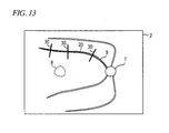
- the reference line 20 is set on the selected blood vessel 9 (that is, in the direction of the blood vessel 9) (S84). As illustrated in Fig. 13 , for the most part, the blood vessel 9 is curved, and thus the reference line 20 is also curved.
- the front image 2 is converted from the still image to a moving image (S85).
- the reference line 20 set on the blood vessel 9 is displayed on the front image 2 (S18), and a tracking process of the reference line 20 starts (S19).
- the cross sectional position 30 is set by the cross sectional position setting process (refer to Fig. 10 ) (S20).
- Fig. 13 exemplifies a case where the cross sectional position 30 is manually set at three locations.
- the controller 70 moves the scanning index in a state in which an angle relative to the curved reference line 20 is maintained. Therefore, the examiner easily and reliably sets the cross sectional position 30 having a predetermined angle relative to a curved part (in this case, the blood vessel 9).
- tracking of the cross sectional position 30 starts (S22), and measurement light is scanned on the cross sectional position 30 (S23).
- the captured tomographic image 5 is displayed as a moving image or a still image on the display portion 75 according to the setting (S24), and the process finishes.
- the controller 70 continuously acquires a plurality of tomographic images 5 which are still images so as to generate the tomographic images 5 as moving images of tissue including the blood vessel 9. Therefore, the examiner can easily make various diagnoses related to the blood vessel 9.
- the ophthalmologic photographing apparatus 10 sets an angle of the cross sectional position 30 to a predetermined angle relative to the reference line 20. Therefore, the examiner can appropriately set the cross sectional position 30 having a predetermined angle relative to a specific direction of tissue. Thus, the examiner can easily make an appropriate diagnosis.
- the ophthalmologic photographing apparatus 10 sets the cross sectional position 30 intersecting the reference line 20 at a predetermined angle. Therefore, the examiner can easily and appropriately make a diagnosis related to the eye E by using the tomographic image 5 based on a direction of tissue.
- the reference line 20 which passes through the papilla 7 and the macula 8 is set, and thus it is possible to easily confirm symmetry centering on the reference line 20 from the tomographic image 5.
- the reference line 20 may be set along the blood vessel 9, and thus the examiner can easily understand a blood vessel diameter, a blood flow rate, a bloodstream, and the like.
- the ophthalmologic photographing apparatus 10 can set the cross sectional position 30 which intersects the reference line 20 so as to be perpendicular thereto. In this case, the examiner can more accurately understand symmetry of tissue with respect to the reference line 20.
- the ophthalmologic photographing apparatus 10 may allow the examiner to designate an angle (relative angle) of the cross sectional position 30 relative to the reference line 20. Therefore, the examiner can more freely and accurately cause the ophthalmologic photographing apparatus 10 to capture a desired tomographic image 5 so as to make a diagnosis.
- the comparison can be performed using tomographic images 5 in which angles relative to a specific direction of tissue correctly match each other. More specifically, in a case where the left and right eyes are compared with each other, the ophthalmologic photographing apparatus 10 according to the present embodiment stores a relative angle of the cross sectional position 30 set when either of the eyes is photographed. Subsequently, when the other eye is photographed, the stored relative angle is horizontally reversed, and the cross sectional position 30 is set to have the reversed relative angle. Thus, the examiner can accurately compare the left eye with the right eye. Further, in a case where the left and right eyes are compared with each other, an angle of the reference line 20 relative to tissue may also be processed in the same manner as in a relative angle of the cross sectional position 30.
- the ophthalmologic photographing apparatus 10 can set the reference line 20 by moving a reference index in response to an operation instruction from the examiner.
- the examiner can easily set a desired reference line 20 while looking at the front image 2 displayed on the display portion 75.
- the ophthalmologic photographing apparatus 10 displays the scanning index on the front image 2 in a superimposition manner in an aspect different from a display aspect of the reference index indicating a position of the reference line 20.
- the ophthalmologic photographing apparatus 10 may move the scanning index in response to an operation instruction from the examiner and may set the cross sectional position 30 on the moved scanning index in a state in which an angle relative to the reference line 20 is fixed.
- the examiner can easily differentiate the reference index from the scanning index so as to accurately set the cross sectional position 30.
- the examiner can freely and accurately set the cross sectional position 30 having a predetermined angle as an angle relative to the reference line 20, at a desired position.
- the ophthalmologic photographing apparatus 10 displays the set reference line 20 on the front image 2 in a superimposition manner. Therefore, the examiner can easily and reliably check, on the front image 2, whether or not the reference line 20 is set an appropriate position.
- the ophthalmologic photographing apparatus 10 displays the front image 2 as a still image on the display portion 75 while receiving an instruction input from the examiner, for setting at least the reference line 20. Therefore, even if the eye E is moved due to involuntary eye movement during fixation, breathing of a subject, or the like, the examiner can easily and reliably set the reference line 20 on the front still image 2.
- the ophthalmologic photographing apparatus 10 can move (track) a position of the reference line 20 on the front image 2 on the basis of a capturing range of the front image 2. For example, even if a capturing range of the front image 2 varies due to involuntary eye movement during fixation after the reference line 20 is set, a position of the reference line 20 relative to captured tissue of the eye E is maintained. Therefore, even if the eye E is moved, the examiner is not required to set the reference line 20 again.
- the ophthalmologic photographing apparatus 10 sets the cross sectional position 30 so that a central position of scanning is located on the reference line 20.
- the examiner can easily confirm the tomographic image 5 centering on the reference line 20.
- the cross sectional position 30 is perpendicular to the reference line 20, the examiner can more accurately understand symmetry of tissue centering on the reference line 20.
- the ophthalmologic photographing apparatus 10 can set the reference line 20 in(along) a direction of the blood vessel 9 in the fundus Ef of the eye E.
- the examiner can easily confirm the topographic image 5 having the direction of the blood vessel 9 as a reference so as to make a diagnosis.
- the ophthalmologic photographing apparatus 10 according to the present embodiment can detect the blood vessel 9 by using the blood vessel extraction algorithm, and can set the reference line 20 in a direction of the blood vessel 9. Therefore, the ophthalmologic photographing apparatus 10 can accurately set the reference line 20 in a direction of the blood vessel 9 without the examiner needing to perform many operations.
- the ophthalmologic photographing apparatus 10 can continuously acquire a plurality of tomographic images 5 so as to generate the topographic images 5 as moving images of tissue including the blood vessel 9. Therefore, the examiner can confirm the tissue including the blood vessel 9 by the moving images. Thus, the examiner can appropriately and accurately understand a blood flow state (for example, a blood flow rate and a bloodstream) of the blood vessel 9 with a simple operation.
- a blood flow state for example, a blood flow rate and a bloodstream
- the present invention is not limited to the above-described embodiment, and may have various modifications.
- the ophthalmologic photographing apparatus 10 captures the tomographic image 5 by using the OCT optical system 100.
- the present invention is not limited to the apparatus including the OCT optical system 100.
- the present invention is applicable to an ophthalmologic photographing apparatus as long as the ophthalmologic photographing apparatus can capture the tomographic image 5 and the front image 2.
- the present invention is also applicable to a case of capturing the tomographic image 5 of parts (for example, an anterior ocular segment) other than the fundus Ef.
- the present invention is also applicable to apparatuses which photograph objects (for example, internal organs, a semiconductor, and the like) other than the eye. More specifically, in a case or the like of checking symmetry of a manufactured semiconductor, if the reference line 20 is set so as to cross a center of a part whose symmetry is to be checked, an operator can easily carry out a useful inspection.
- the linear reference line 20 is set, and if the "blood vessel diagnosis mode” is selected, the reference line 20 along the blood vessel 9 is set.
- an aspect of the reference line 20 is not limited thereto.
- the ophthalmologic photographing apparatus 10 may set the reference line 20 with other shapes such as an arc shape and a polygonal shape.
- the cross sectional position 30 having a predetermined angle as an angle relative to the reference line 20 may be set.
- the ophthalmologic photographing apparatus 10 sets the cross sectional position 30 which intersects the reference line 20 at a predetermined angle. Therefore, the examiner can easily understand the tomographic image 5 in a direction of which the tomographic image 5 intersects the reference line 20.
- the ophthalmologic photographing apparatus 10 may stipulate only an angle of the cross sectional position 30 relative to the reference line 20 without intersection between the reference line 20 and the cross sectional position 30. Also in this case, the examiner can appropriately set the cross sectional position 30 having a predetermined angle relative to a specific direction of tissue. Therefore, the ophthalmologic photographing apparatus 10 may set the cross sectional position 30 parallel to the reference line 20 or the like.
- the ophthalmologic photographing apparatus 10 may perform scanning (and thus raster scanning) at a plurality of cross sectional positions 30 which are parallel to the reference line 20 and have different distances from the reference line 20, so as to acquire three-dimensional data or map data of an object to be examined.
- the examiner can make an appropriate diagnosis by using the data which is acquired through the scanning in the appropriate direction.
- the ophthalmologic photographing apparatus 10 may set the cross sectional position 30 in a tangential direction of the reference line 20.
- the cross sectional position 30 may be invariably set to be perpendicular to the reference line 20.
- the ophthalmologic photographing apparatus 10 sets the cross sectional position 30 so that a central position of scanning is located on the reference line 20. Therefore, the examiner can easily confirm the tomographic image 5 centering on the reference line 20. However, the present invention can be realized even if a central position of scanning is not located on the reference line 20.
- the ophthalmologic photographing apparatus 10 can set the reference line 20 in any method of "papilla and macula automatic setting", “direct manual setting", and "passing point manual setting".
- the ophthalmologic photographing apparatus 10 preferably performs at least one process of setting the reference line 20.
- a description has been made of a case of setting the reference line 20 which passes through both the papilla and the macula.
- a position where the reference line 20 is set may be changed.
- the reference line 20 which passes through a lesion part and the papilla may be set.
- the reference line 20 which passes through a lesion part and the macula may be set.
- the reference line 20 which passes through the lesion part may be automatically set using the image process.
- a photographing mode is first selected, and a process such as setting of the reference line 20 is performed on the basis of the selected mode.
- a setting method of the reference line 20 may be set and changed in the middle of the photographing.
- a reference line setting method, a relative angle and cross sectional position setting method, reference line photographing, and a display method are set in advance, and then a process such as setting of the reference line 20 is performed (refer to Figs. 4 and 5 ).
- timings for performing various settings may be changed as appropriate.
- the ophthalmologic photographing apparatus 10 may set or change a relative angle after setting the reference line 20.
- the ophthalmologic photographing apparatus 10 may freely change a cross sectional position setting method in the cross sectional position setting process (refer to Fig. 10 ).
- the ophthalmologic photographing apparatus 10 may change a display method (a moving image or a still image) at any timing in response to an operation instruction from the examiner.
- the cross sectional position setting method may also be changed. For example, even in a case where the option "manual" is selected, the examiner may designate the number of cross sectional positions or a space therebetween.
- a specific setting method of the reference line 20 may be changed as appropriate.
- the ophthalmologic photographing apparatus 10 may select the reference line 20 without allowing the examiner to select either of the options "direct manual setting" and "passing point manual setting" in advance.
- the ophthalmologic photographing apparatus 10 may perform, for example, the second reference line setting process (refer to Fig. 8 ) when the reference index is dragged, and may perform the third reference line setting process (refer to Fig. 9 ) when a passing point is designated due to clicking.
- the ophthalmologic photographing apparatus 10 may set the reference line 20 based on an operation instruction from the examiner, in methods other than the options "direct manual setting" and "passing point manual setting".
- the controller 70 may set one point designated through a click operation as a passing point of the reference index, and may set the reference line 20 by changing an angle or the like of the reference index under a condition that the reference index passes through the passing point.
- the linear reference index and reference line 20 are displayed on the front image 2 so as to cross the entire display region of the display portion 75. Therefore, the examiner can accurately perform an operation while looking at an image even in a case where the reference line 20 is set to pass through two points which are spaced far apart from each other on the front image 2.
- the reference index and the reference line 20 may be lines with a specific length.
- the ophthalmologic photographing apparatus 10 displays the set reference line 20 on the front image 2. Therefore, the examiner can easily check whether or not the reference line 20 is correctly set.
- the cross sectional position 30 may be set without displaying the reference line 20. In other words, the ophthalmologic photographing apparatus 10 may set the reference line 20 on the front image 2 which is internally acquired.
- the examiner can more easily confirm setting content.
- the scanning index and the set cross sectional position 30 may be displayed in different display aspects.
- the ophthalmologic photographing apparatus 10 receives designation of a position of the reference line 20 on the front image 2 which is a still image. Therefore, the examiner can easily and reliably set the reference line 20 even in a case where the eye is moved. However, designation of a position of the reference line 20 on the front image 2 which is a moving image may be received. Also in this case, a process of tracking a position of the reference line 20 is performed after the reference line 20 is set, and thus it is possible to alleviate an operation burden on the examiner. In addition, the ophthalmologic photographing apparatus 10 may not only display a still image during setting of the reference line 20, but may also continuously display the still image during setting of the cross sectional position 30 which is subsequently performed.
- a case where a single reference line 20 is set has been exemplified.
- a plurality of reference lines 20 may be set on the front image 2.
- the ophthalmologic photographing apparatus 10 may adjust the reference line 20 which is temporarily set, in response to an operation instruction from the examiner.
- An adjustment processing method may employ the same method as the above-described processing method in S45.
- the ophthalmologic photographing apparatus 10 can automatically detect the blood vessel 9 and can set the reference line 20 along the detected blood vessel 9. Therefore, the examiner can accurately and easily set the reference line 20 on the blood vessel 9.
- a method of setting the reference line 20 on the blood vessel 9 may be changed.
- the ophthalmologic photographing apparatus 10 may determine a trajectory of the pointer which is moved in response to an operation instruction from the examiner, as a shape of the blood vessel 9, and may set the reference line 20 on the trajectory.
- the ophthalmologic photographing apparatus 10 may set the reference line 20 along a trajectory which is drawn on a touch panel.
- the ophthalmologic photographing apparatus 10 allows the examiner to select one or a plurality of blood vessels 9 on which the reference line 20 is to be set, in a case where a plurality of blood vessels 9 are automatically detected. Therefore, the examiner can easily make a diagnosis related to a desired blood vessel 9.
- the ophthalmologic photographing apparatus 10 may set the reference line 20 on all of the automatically detected blood vessels 9.
- the ophthalmologic photographing apparatus 10 may set a plurality of cross sectional positions so that the cross sectional positions do not intersect each other. Specifically, the ophthalmologic photographing apparatus 10 may prevent intersection between the cross sectional positions by adjusting a space between positions of the plurality of adjacent cross sectional positions. The intersection may be prevented by adjusting a length of the cross sectional position. The intersection between the cross sectional positions is prevented, and thus the same part is not shown in a plurality of tomographic images, thereby increasing efficiency of diagnosis.
- the ophthalmologic photographing apparatus 10 sets the reference line 20 before capturing a tomographic image, and sets the cross sectional position 30 which is a position where measurement light is scanned so that an angle relative to the set reference line 20 becomes a predetermined angle.
- the case may be performed by modifying the above-described embodiment.
- An embodiment of this modification example is exemplified.
- An image processing apparatus for example, the ophthalmologic photographing apparatus 10, the PC, or the like
- which processes a tomographic image preliminarily acquires three-dimensional data (three-dimensional image) of an object, obtained by performing raster scanning of measurement light.
- display process which is a modification of the process of Fig. 6
- a tomographic image at the set cross sectional position is acquired from the three-dimensional data instead of scanning of measurement light in S23.
- the acquired tomographic image is displayed in S24.
- the front image displayed in S11 may be a still image.
- the tracking (S 18) of the reference line 20 and the tracking (S22) of the cross sectional position may not be performed. Further, other processes such as the cross sectional position setting process (refer to Fig. 10 ) may generally employ the processes exemplified in the above-described embodiment.
- An image processing program which is executed by the image processing apparatus of this modification example may have the following configuration. "An image processing program is executed in an image processing apparatus which acquires a two-dimensional tomographic image of an object from three-dimensional data of the object, and is executed by a processor of the image processing apparatus so as to cause the image processing apparatus to perform: a three-dimensional data acquisition step of acquiring the three-dimensional data; a display control step of displaying a front image of the object on display means; an instruction reception step of receiving an input of an instruction from an examiner; a reference line setting step of setting a reference line which is used as a reference for setting a cross sectional position which is a position where the tomographic image is acquired, on the front image, in response to the instruction received in the instruction reception step; a cross sectional position setting step of setting the cross sectional position having a predetermined angle as an angle relative to the reference line set in the reference line setting step; and a tomographic image acquisition step of acquiring the tomographic image at the cross sectional position set in
- the controller 70 provided in the ophthalmologic photographing apparatus 10 controls all operations of the ophthalmologic photographing apparatus 10.
- a device which controls some of the operations of the ophthalmologic photographing apparatus 10 may be used separately from the ophthalmologic photographing apparatus 10.
- a PC is connected to the ophthalmologic photographing apparatus 10, and the PC may perform at least some of processes such as setting of the reference line 20 and setting of the cross sectional position 30.
- the PC may execute at least a part of the above-described photographing control program by using a processor.
Landscapes
- Health & Medical Sciences (AREA)
- Life Sciences & Earth Sciences (AREA)
- Medical Informatics (AREA)
- Biophysics (AREA)
- Ophthalmology & Optometry (AREA)
- Engineering & Computer Science (AREA)
- Biomedical Technology (AREA)
- Heart & Thoracic Surgery (AREA)
- Physics & Mathematics (AREA)
- Molecular Biology (AREA)
- Surgery (AREA)
- Animal Behavior & Ethology (AREA)
- General Health & Medical Sciences (AREA)
- Public Health (AREA)
- Veterinary Medicine (AREA)
- Nuclear Medicine, Radiotherapy & Molecular Imaging (AREA)
- Radiology & Medical Imaging (AREA)
- Eye Examination Apparatus (AREA)
Abstract
Description
- This application is based upon and claims the benefit of priority of Japanese Patent Application No.
2013-010442 filed on January 23, 2013 - The present disclosure relates to an image processing technique which processes a tomographic image of an eye to be examined.
- For an ophthalmologic photographing apparatus which can noninvasively capture a tomographic image of a predetermined part (for example, a fundus or an anterior ocular segment) of an eye to be examined, optical coherent tomography (OCT) using low coherent light is known (for example, refer to
JP-A-2008-29467 - There is a case where a cross sectional position is set to have a predetermined angle relative to a specific direction of tissue of an eye to be examined so as to acquire or generate a tomographic image, thereby obtaining useful information. However, it is difficult to appropriately set the cross sectional position having the predetermined angle relative to the specific direction in the ophthalmologic photographing apparatus of the related art.
- An object of the present disclosure is to provide an image processing apparatus capable of appropriately setting a cross sectional position for acquiring or generating a tomographic image of tissue of an eye, to have a predetermined angle relative to a specific direction of the tissue.
- An aspect of the present disclosure provides the following arrangements:
- (1) An image processing apparatus configured to process a tomographic image of an object to be examined, comprising:
- reference line setting means for setting a reference line, which is used as a reference for setting a cross sectional position, on a front image of the object, the cross sectional position being a position where a two-dimensional topographic image is acquired from three-dimensional data of the object, or a position where measurement light for generating a tomographic image is scanned; and
- cross sectional position setting means for setting the cross sectional position having a predetermined angle as an angle relative to the set reference line.
- (2) The image processing apparatus according to (1), wherein the cross sectional position setting means sets the cross sectional position which intersects the reference line at a predetermined angle.
- (3) The image processing apparatus according to (2), wherein the cross sectional position setting means sets the cross sectional position which perpendicularly intersects the reference line.
- (4) The image processing apparatus according to (1), wherein the cross sectional position setting means receives designation of an angle of the cross sectional position relative to the reference line, and sets the cross sectional position having the designated angle as an angle relative to the reference line.
- (5) The image processing apparatus according to any one of (1) to (4), wherein the cross sectional position setting means locates a center of the cross sectional position on the reference line.
- (6) The image processing apparatus according to (1), wherein the cross sectional position setting means sets the cross sectional position which is parallel to the reference line.
- (7) The image processing apparatus according to any one of (1) to (6) further comprising:
- three-dimensional data acquisition means for acquiring three-dimensional data of the object; and
- topographic image acquisition means for acquiring a tomographic image at the cross sectional position set in the front image based on the three-dimensional data.
- (8) The image processing apparatus according to any one of (1) to (6) further comprising:
- scanning control means for controlling driving of scanning means for scanning the measurement light on the tissue of the object in such a manner that the measurement light is scanned on tissue corresponding to the cross sectional position set in the front image.
- (9) The image processing apparatus according to (6), further comprising raster scanning control means for controlling driving of scanning means for scanning the measurement light on the tissue of the object in such a manner that the measurement light is scanned on tissue corresponding to a plurality of cross sectional positions set to be parallel to the reference line.
- (10) The image processing apparatus according to any one of (1) to (9), wherein the reference line setting means sets at least one of the reference line and the cross sectional position in response to an instruction input from the examiner while the front image which is a still image is displayed on display means.
- (11) The image processing apparatus according to any one of (1) to (10), further comprising:
- tracking means for detecting positional deviation of the front image after the reference line is set with respect to the front image when the reference line setting means sets the reference line through an image process, and tracking a position of the reference line after the reference line is set to a correct position on the front image based on the result of the detected positional deviation.
- (12) The image processing apparatus according to any one of (1) to (11), wherein the reference line setting means performs an image process on the front image, and automatically sets the reference line on the basis of a result of the image process.
- (13) The image processing apparatus according to (12), wherein the reference line setting means detects positions of a papilla and a macula of an eye which is the object by performing an image process on the front image, and automatically sets the linear reference line which passes through both of the detected papilla and macula.
- (14) The image processing apparatus according to (12), wherein the reference line setting means performs a blood vessel detection process on the front image by using a blood vessel extraction algorithm, and sets the reference line in a direction of the detected blood vessel.
- (15) The image processing apparatus according to (14) further comprising:
- blood vessel moving image generation means for generating the topographic image as moving images of the tissue including the blood vessel, by continuously acquiring a plurality of tomographic images each of which is obtained by scanning the measurement light on the tissue of the object corresponding to a single cross sectional position.
- (16) A method of controlling an image processing apparatus configured to process a tomographic image of an object to be examined, the method comprising:
- setting a reference line, which is used as a reference for setting a cross sectional position, on a front image of the object, the cross sectional position being a position where a two-dimensional tomographic image is acquired from three-dimensional data of the object, or a position where measurement light for generating a tomographic image is scanned; and
- setting the cross sectional position having a predetermined angle as an angle relative to the set reference line.
- According to the technique of the present disclosure, it is possible to appropriately set a cross sectional position for acquiring or generating a tomographic image of tissue of an eye, at a predetermined angle with respect to a specific direction of the tissue.
-
-
Fig. 1 is a diagram illustrating a schematic configuration of anophthalmologic photographing apparatus 10. -
Fig. 2 is a diagram illustrating examples of afront image 2 and atomographic image 5 displayed on adisplay portion 75. -
Fig. 3 is a flowchart illustrating a mode setting process performed by theophthalmologic photographing apparatus 10. -
Fig. 4 is a diagram illustrating an example of a designated part diagnosis modecondition setting screen 15. -
Fig. 5 is a diagram illustrating an example of a blood vessel diagnosis modecondition setting screen 16. -
Fig. 6 is a flowchart illustrating a designated part photographing process performed by theophthalmologic photographing apparatus 10. -
Fig. 7 is a flowchart illustrating a first reference line setting process which is performed in the designated part photographing process. -
Fig. 8 is a flowchart illustrating a second reference line setting process which is performed in the designated part photographing process. -
Fig. 9 is a flowchart illustrating a third reference line setting process which is performed in the designated part photographing process. -
Fig. 10 is a flowchart illustrating a cross sectional position setting process which is performed in the designated part photographing process. -
Fig. 11 is a diagram exemplifying a state in which five crosssectional positions 30 are set on the basis of areference line 20 set in a designated part. -
Fig. 12 is a flowchart illustrating a blood vessel photographing process performed by theophthalmologic photographing apparatus 10. -
Fig. 13 is a diagram exemplifying a state in which three crosssectional positions 30 are set on the basis of areference line 20 set in ablood vessel 9. - Hereinafter, an exemplary embodiment of the present disclosure will be described with reference to the drawings. In the following description, an axis direction of an eye E to be examined is set to a Z direction, a horizontal direction is set to an X direction, and a vertical direction is set to a Y direction. A surface direction of the fundus may be considered to be an XY direction.
- With reference to
Fig. 1 , a schematic configuration of anophthalmologic photographing apparatus 10 according to the present embodiment will be described. The ophthalmologic photographing apparatus (optical coherence tomographic apparatus) 10 according to the present embodiment includes an OCToptical system 100, an observationoptical system 200, a fixationtarget projection unit 300, and acontroller 70. - The OCT
optical system 100 is an interference optical system which acquires a tomographic image of tissue (for example, the fundus Ef) of the eye E, and has a configuration of optical coherence tomography (OCT). Specifically, the OCToptical system 100 includes ameasurement light source 102, a coupler (light splitter) 104, a measurementoptical system 106, a referenceoptical system 110, and a detector (light receiving element) 120. - The
measurement light source 102 emits light for acquiring a tomographic image. Thecoupler 104 splits the light emitted from themeasurement light source 102 into measurement light (sample light) and reference light. Thecoupler 104 combines measurement light which is reflected by the fundus Ef and reference light generated by the referenceoptical system 110 and allows thedetector 120 to receive the combined light. - The measurement
optical system 106 guides the measurement light split by thecoupler 104 to the fundus Ef of the eye E. Specifically, the measurementoptical system 106 includes alight scanner 108 at a position which is substantially conjugate to the pupil. The measurementoptical system 106 drives thelight scanner 108 by using adriving mechanism 50 so as to scan the measurement light on the fundus Ef in a two-dimensional direction. As a result, a capturing position of a tomographic image on the fundus Ef is determined. In other words, a cross sectional position of the measurement light which is scanned by thelight scanner 108 becomes a capturing position of a tomographic image. For example, a variety of devices which deflect light, such as a reflection mirror (a galvano mirror, a polygon mirror, or a resonant scanner) and an acoustic optical modulator (AOM) may be used as thelight scanner 108. - The reference
optical system 110 generates reference light. As described above, the reference light is combined with the reflected light of the measurement light from the fundus Ef. The referenceoptical system 110 may be of a Michelson type and of a Mach-Zehnder type. In the present embodiment, the referenceoptical system 110 reflects the light guided by thecoupler 104 by using a reflection optical system which includes a reference mirror and the like. The reflected light is returned to thecoupler 104 again as reference light. A configuration of the referenceoptical system 110 may be changed. For example, the referenceoptical system 110 may not reflect the light guided by thecoupler 104 but may transmit the light through thedetector 120 by using a transmission optical system such as an optical fiber. - The OCT
optical system 100 changes an optical path length difference between the measurement light and the reference light. The OCToptical system 100 according to the present embodiment changes the optical path length difference by moving an optical member (specifically, the reference mirror) included in the referenceoptical system 110 in an optical axis direction. A configuration for changing an optical path length difference may be disposed in a measurement optical path of the measurementoptical system 106. - The
detector 120 detects an interference state of the measurement light and the reference light. In a case of Fourier domain OCT, a spectral intensity of interference light is detected by thedetector 120, and a depth profile (an A scan signal) in a predetermined range is acquired through Fourier transform of the spectral intensity data. The ophthalmologic photographingapparatus 10 may employ a variety of OCT. For example, theophthalmologic photographing apparatus 10 may employ any one of spectral-domain OCT (SD-OCT), swept-source OCT (SS-OCT), and time-domain OCT (TD-OCT). - The observation
optical system 200 is provided so as to acquire a front image of tissue (the fundus Ef in the present embodiment) of the eye E. The observationoptical system 200 according to the present embodiment has a configuration of a so-called scanning laser ophthalmoscope (SLO). More specifically, the observationoptical system 200 includes a light scanner and a light receiving element (not illustrated). The light scanner scans measurement light (for example, infrared light) emitted from the light source on the fundus Ef in a two-dimensional direction. The light receiving element receives reflected light of the measurement light from the fundus Ef, via a confocal aperture disposed at a position which is substantially conjugate to the fundus Ef. - The observation
optical system 200 may employ a configuration (a so-called fundus camera type configuration) of acquiring a front image such as a still image and a moving image by widely applying infrared light or the like. Further, the OCToptical system 100 may be also used as the observationoptical system 200. In other words, theophthalmologic photographing apparatus 10 may acquire a front image of the tissue by using data acquired by the OCToptical system 100, the data being used to generate a tomographic image. More specifically, theophthalmologic photographing apparatus 10 may acquire a front image by using an integrated image of a three-dimensional tomographic image in a depth direction, an integrated value of spectrum data at respective positions in the XY direction, luminance data at respective positions in the XY direction in a specific depth direction, a retinal surface image, and the like. - The
controller 70 described later may perform alignment (matching) between a front image acquired by the observationoptical system 200 and an image (for example, a two-dimensional image from a front direction, obtained by integrating data of a three-dimensional image in the depth direction) acquired by the OCToptical system 100. In this case, thecontroller 70 may correlate the three-dimensional image with the front image so as to perform processes such as display and analysis on the correlated images. - The fixation
target projection unit 300 is provided so as to induce a visual line direction of the eye E. In the present embodiment, the fixationtarget projection unit 300 includes a visible light source which generates visible light, and changes a presentation position of an index shown by the visible light source. As a result, the visual line direction of the eye E is changed, and thus a photographing part of the fundus Ef is changed. For example, when a fixation target is presented from the same direction as a photographing optical axis, a central part of the fundus Ef becomes a photographing part. When the fixation target is presented over the photographing optical axis, an upper part of the fundus Ef becomes a photographing part. The fixationtarget projection unit 300 may employ various configurations. For example, a configuration may be employed in which a fixation position is adjusted by turning-on positions of LEDs which are arranged in a matrix. A configuration may be employed in which visible light is scanned using a light scanner. The fixationtarget projection unit 300 may be of an inner fixation lighting type in which a fixation target is displayed inside the device, and may be of an outer fixation lighting type in which a fixation target is displayed outside the device. - The
controller 70 includes a CPU (processor), a RAM, a ROM, and the like. The CPU of thecontroller 70 controls theophthalmologic photographing apparatus 10. The RAM temporarily stores various information. Various programs, initial values, and the like for controlling an operation of the ophthalmologic photographingapparatus 10 are stored in the ROM of thecontroller 70. - The
controller 70 is electrically connected to anonvolatile memory 72, anoperation portion 74, adisplay portion 75, and the like. Thenonvolatile memory 72 is a non-transitive storage medium which can hold storage content even if the supply of power is cut off. For example, a hard disk drive, a flash ROM, a USB memory attachable to and detachable from theophthalmologic photographing apparatus 10, and the like, may be used as thenonvolatile memory 72. A photographing control program for controlling capturing of a front image and a tomographic image, performed by theophthalmologic photographing apparatus 10, is stored in thenonvolatile memory 72. In addition, a two-dimensional tomographic image, a three-dimensional image, and a front image, which are captured, and various information regarding photographing such as information regarding a capturing position of a tomographic image, are stored in thenonvolatile memory 72. Various operation instructions are input to theoperation portion 74 by an examiner. - The
operation portion 74 outputs a signal corresponding to an input operation instruction to thecontroller 70. At least one of, for example, a mouse, a joystick, a keyboard, a touch panel, and the like may be used in theoperation portion 74. Thedisplay portion 75 may be a display mounted in a main body of the ophthalmologic photographingapparatus 10, and may be a display connected to the main body. A display of a personal computer (hereinafter, referred to as a "PC") may be used. A plurality of displays may be used together. Various images including a tomographic image and a front image captured by theophthalmologic photographing apparatus 10 are displayed on thedisplay portion 75. - The
controller 70 may be constituted by a plurality of controllers (that is, a plurality of processors). For example, thecontroller 70 of the ophthalmologic photographingapparatus 10 may be constituted by a setting controller provided in a PC and an operation controller which controls an operation of the OCToptical system 100 or the like. In this case, for example, the setting controller of the PC may set a capturing position of a tomographic image on the basis of an operation of the operation portion connected to the PC, and may instruct the operation controller to perform the setting content. The operation controller may control a photographing operation of each constituent element of the ophthalmologic photographingapparatus 10 on the basis of the instruction from the setting controller. A process of generating (acquiring) an image on the basis of a light receiving signal may be performed by either of the operation controller and the setting controller. - With reference to
Fig. 2 , an outline of image capturing according to the present embodiment will be described. The ophthalmologic photographingapparatus 10 according to the present embodiment can appropriately set an acquisition position (that is, a cross sectional position of measurement light) of a tomographic image to have a predetermined angle relative to a specific direction of tissue (for example, the fundus Ef) of the eye E. There is a case where the cross sectional position is set to have the predetermined angle relative to the specific direction of the tissue, and thus a tomographic image useful for diagnosis is obtained. For example, in recent years, research results have been published in which the fundus Ef is divided using a line which passes through apapilla 7 and a macula 8 (refer toFig. 2 ) as a boundary, and a relationship or the like between a structural change such as symmetry of retina thickness and a lesion is mentioned. If a cross sectional position is made to intersect the line passing through thepapilla 7 and the macula 8, an examiner can easily judge symmetry of tissue in which the line serves as a boundary, from a tomographic image. In addition, in a case where a cross sectional position is made to intersect a blood vessel 9 (refer toFig. 2 ), the examiner can easily judge a blood vessel diameter, a blood flow rate, a bloodstream, and the like from a tomographic image. Information useful to the examiner may be obtained by setting an angle of a cross sectional position depending on a lesion part. Further, useful information may be obtained by setting a cross sectional position parallel to a direction of tissue. - As illustrated in
Fig. 2 , theophthalmologic photographing apparatus 10 according to the present embodiment sets areference line 20 which is used as a reference for setting a crosssectional position 30, on afront image 2. The crosssectional position 30 having a predetermined angle as an angle relative to the setreference line 20 is set. Measurement light is scanned on tissue corresponding to the set crosssectional position 30, thereby obtaining afundus image 5. Therefore, theophthalmologic photographing apparatus 10 can appropriately set the crosssectional position 30 having a predetermined angle relative to a specific direction of the tissue. As a result, it is possible to easily obtain thetomographic image 5 useful for diagnosis. - A description will be made of photographing modes which can be executed by the
ophthalmologic photographing apparatus 10 according to the present embodiment. The ophthalmologic photographingapparatus 10 can execute a "designated part diagnosis mode", a "blood vessel diagnosis mode", and a "normal mode". In the "designated part diagnosis mode", thelinear reference line 20 is set at a part designated by the examiner, and an angle of the crosssectional position 30 is set on the basis of the setreference line 20. Therefore, the examiner just sets thereference line 20 in a desired direction at a desired part, and thus can easily set the crosssectional position 30 having a suitable angle. In the "blood vessel diagnosis mode", thereference line 20 is set along theblood vessel 9, and an angle of the crosssectional position 30 is set on the basis of the setreference line 20. Therefore, according to the "blood vessel diagnosis mode", the examiner can easily make a diagnosis related to theblood vessel 9. In the "normal mode", the crosssectional position 30 is set without setting thereference line 20. Hereinafter, a description of the "normal mode" will be made briefly. - With reference to
Figs. 3 to 5 , a mode setting process performed by thecontroller 70 of the ophthalmologic photographingapparatus 10 will be described. In the mode setting process, any one of the "designated part diagnosis mode", the "blood vessel diagnosis mode", and the "normal mode" is selected by the examiner. In addition, a photographing condition for executing a selected mode is set on the basis of an instruction from the examiner. When an instruction for setting a photographing mode is input to theoperation portion 74, thecontroller 70 performs the mode setting process illustrated inFig. 3 according to the photographing control program stored in thenonvolatile memory 72. - In a case where the mode setting process starts, a selection screen (not illustrated) which allows the examiner to select a photographing mode is displayed on the
display portion 75. The examiner operates the operation portion 74 (for example, a touch panel, a mouse, or the like) so as to input a mode selection instruction. If the selected mode is the "designated part diagnosis mode" (S1: YES), a designated part photographing condition setting process is performed (S2), and the mode setting process finishes. If the selected mode is not the "designated part diagnosis mode" (S1: NO) but the "blood vessel diagnosis mode" (S4: YES), a blood vessel photographing condition setting process is performed (S5), and the mode setting process finishes. If the "normal mode" is selected (S4. NO), a normal photographing condition setting process is performed (S6), and the process finishes. - As illustrated in
Fig. 4 , in the designated part photographing condition setting process (S2), a designated part photographingcondition setting screen 15 is displayed on thedisplay portion 75. In the designated part photographingcondition setting screen 15, a reference line setting method selection item, a relative angle selection item, a cross sectional position setting method selection item, and a reference line photographing selection item are provided. The examiner operates theoperation portion 74 so as to select any one of a plurality of options in each item. Thecontroller 70 sets a photographing condition on the basis of the selection performed by the examiner. - The reference line setting method is a method of setting the
reference line 20 on thefront image 2. The reference line setting method according to the present embodiment includes options such as "papilla and macula automatic setting", "direct manual setting", and "passing point manual setting". In the option "papilla and macula automatic setting", thereference line 20 passing through thepapilla 7 and the macula 8 is automatically set. In the option "direct manual setting", the examiner may manually set thereference line 20 having a desired angle at a desired position by moving a reference index which is displayed on thefront image 2 in a superimposition manner. In the option "passing point manual setting", the examiner may set thereference line 20 passing through two passing points by manually setting the two passing points on thefront image 2. - The relative angle is an angle of the cross
sectional position 30 relative to thereference line 20. In the present embodiment, the examiner may select either of the options "perpendicular" and "arbitrary designation". If the examiner selects the option "perpendicular", the crosssectional position 30 perpendicular to thereference line 20 is set. If the examiner selects the option "arbitrary designation", a state in which an angle can be input occurs, and an input angle is set as the relative angle. - The cross sectional position setting method is a method of setting the cross
sectional position 30 on the basis of thereference line 20. In the present embodiment, any one of options such as "manual", "number designation", and "space designation" may be selected. In the option "manual", the examiner may manually set a desired number of crosssectional positions 30 of which an angle relative to thereference line 20 is the relative angle, at desired positions. In the option "number designation", when the examiner designates the number of crosssectional positions 30, the crosssectional positions 30 of the designated number are set with equal spaces therebetween. In the option "space designation", a plurality of cross sectional positions are set between two end points on thereference line 20 with spaces therebetween designated by the examiner. - The reference line photographing indicates whether or not the cross
sectional position 30 is set on thereference line 20. If an option of "YES" is selected, the crosssectional position 30 is also set on thereference line 20 in addition to the crosssectional position 30 intersecting thereference line 20. If an option of "NO" is selected, the crosssectional position 30 along thereference line 20 is not set. - As illustrated in
Fig. 5 , in the blood vessel photographing condition setting process (S5), a blood vessel photographingcondition setting screen 16 is displayed on thedisplay portion 75. In the blood vessel photographingcondition setting screen 16, a relative angle selection item, a cross sectional position setting method selection item, and a display method selection item are provided. The relative angle selection item and the cross sectional position setting method selection item are the same as in the designated part photographing condition setting screen 15 (refer toFig. 4 ). The display method is a method of displaying a tomographic image of theblood vessel 9. The examiner may select either of display methods of "moving image" and "still image". - With reference to
Figs. 6 to 11 , a designated part photographing process performed by thecontroller 70 will be described. In the designated part photographing process, the fundus Ef is photographed in the "designated part diagnosis mode". When the "designated part diagnosis mode" is selected in the mode setting process (refer toFig. 3 ), thecontroller 70 performs the designated part photographing process illustrated inFig. 6 according to the photographing control program stored in thenonvolatile memory 72. - First, the observation optical system 200 (refer to
Fig. 1 ) starts to capture afront image 2 of the fundus Ef so as to display moving images in real time on the display portion 75 (S11). If a reference line setting method selected by the examiner is the option "papilla and macula automatic setting" (S12: YES), a first reference line setting process is performed (S13), and the process proceeds to S18. If the option "direct manual setting" is selected (S12: NO, and S14: YES), a second reference line setting process is performed (S15), and the process proceeds to S 18. If the option "passing point manual setting" is selected (S14: NO), a third reference line setting process is performed (S16), and the process proceeds to S18. - As illustrated in
Fig. 7 , in the first reference line setting process, the latest captured still image of thefront image 2 is acquired as a reference image and is stored in the RAM (S31). A well-known image process is performed on the reference image, and thus a position of thepapilla 7 and a position of the macula 8 (refer toFig. 11 ) are detected (S32). As an algorithm for the image process, any one of various algorithms such as edge detection and Hough conversion algorithms may be used. Next, thelinear reference line 20 which passes through both of the detectedpapilla 7 and macula 8 is set on the reference image (S33). The process returns to the designated part photographing process (refer toFig. 6 ). Due to the above-described process, thereference line 20 which passes through thepapilla 7 and the macula 8 is automatically set. - As illustrated in
Fig. 8 , in the second reference line setting process, a reference index which is used as an index for setting thereference line 20 is displayed on thefront image 2 in a superimposition manner (S41). In the present embodiment, for example, the reference index is displayed by the broken line in the same manner as in the display aspect of thereference line 20 illustrated inFig. 2 . Next, it is determined whether or not a drag operation of the reference index is started by the examiner (S42). In the present embodiment, the examiner operates the mouse of theoperation portion 74 so as to move a pointer to the reference index, and drags the pointer so as to move the reference index. However, a method of moving the reference index may be changed. A standby state occurs until the drag operation is performed (S42: NO). In addition, thecontroller 70 rotates the reference index displayed on thefront image 2 on the basis of a predetermined operation (for example, a right click operation of the mouse, a rotation operation of the wheel, an operation on the keyboard, and the like) on theoperation portion 74. - When the drag operation is started (S42: YES), the
front image 2 which is currently displayed as moving images is stopped as the latest still image (S44). The reference index is moved on thefront image 2 which is a still image in response to an operation on the operation portion 74 (S45). Therefore, the examiner can easily set thereference line 20 on the still image without being influenced by involuntary eye movement or the like during fixation. The process in S45 is continuously performed until the drag operation is finished (S46: NO). If the drag operation is finished (S46: YES), thereference line 20 is set on the moved reference index (S48). Thefront image 2 which is currently displayed as a still image is converted into a moving image (S49), and the process returns to the designated part photographing process (refer toFig. 6 ). Due to the above-described process, thelinear reference line 20 is directly manually set by the examiner. For example, in a case where the examiner wishes to set thereference line 20 illustrated inFig. 11 , the reference index may be moved to positions which pass through both of thepapilla 7 and the macula 8. - As illustrated in
Fig. 9 , in the third reference line setting process, thefront image 2 which is currently displayed as a moving image is converted into the latest still image (S51). In the present embodiment, the examiner moves the pointer displayed on thefront image 2 which is a still image with the mouse and performs a click operation, so as to designate positions of passing points of thereference line 20. When the click operation is performed, thecontroller 70 sets points designated by the click operation as the passing points (S52). The process in S52 is repeatedly performed until setting of two passing points is completed (S54: NO). If the setting of two passing points is completed (S54: YES), thereference line 20 which passes through both passing points is set (S55). Thefront image 2 which is currently displayed as a still image is converted into a moving image (S56), and the process returns to the designated part photographing process (refer toFig. 6 ). Due to the above-described process, the examiner just manually sets two passing points at desired positions on thefront image 2, so as to set thereference line 20. For example, in a case where the examiner wishes to set thereference line 20 illustrated inFig. 11 , a passing point may be set at each of thepapilla 7 and the macula 8. In addition, the examiner can easily set thereference line 20 which crosses a lesion part or the like in a predetermined direction. -
Fig. 6 will be continuously described. When thereference line 20 is set, theset reference line 20 is displayed on thefront image 2 in a superimposition manner (S18). Subsequently, a reference line tracking process starts (S19). The reference line tracking process is a process of causing a position of thereference line 20 to track a correct position on thefront image 2 which is currently displayed as a moving image. In the present embodiment, positional deviation of the front image 2 (that is, the latest front image 2) on which thereference line 20 has been set, relative to thefront image 2 as a still image on which thereference line 20 was set, is detected through the above-described image process. Parameters of the detected positional deviation include a direction, a distance, and an angle. Thecontroller 70 moves a position of thereference line 20 by a detected distance in a detected direction, and also rotates thereference line 20 by a detected angle. As a result, thereference line 20 tracks a correct position. - In addition, in a case of detecting positional deviation, the
controller 70 is not required to directly compare allfront images 2 which are continuously captured, with thefront image 2 on which thereference line 20 was set. For example, thecontroller 70 may repeatedly detect positional deviation between the latestfront image 2 and thefront image 2 which is previously captured. Also in this method, it is possible to detect positional deviation of the latestfront image 2 relative to thefront image 2 on which thereference line 20 was set. Further, thecontroller 70 may change thefront image 2 which is a comparison target every time a predetermined number offront images 2 as a still image are captured. Furthermore, thecontroller 70 may detect a relative position of thereference line 20 for a feature point on thefront image 2, and may cause thereference line 20 to track the detected relative position so that the detected relative position is maintained. - Next, a cross sectional position setting process is performed (S20). In the cross sectional position setting process, the cross
sectional position 30 of measurement light (that is, a capturing position of a tomographic image) is set on the basis of thereference line 20 set in S12 to S16. - As illustrated in
Fig. 10 , when the cross sectional position setting process starts, the relative angle set in the mode setting process (refer toFig. 3 ) is acquired (S61). As described above, the relative angle is an angle of the crosssectional position 30 relative to thereference line 20. In the present embodiment, the examiner may select the option "perpendicular" as the relative angle, and may designate a desired relative angle with the option "arbitrary designation". Next, it is determined whether or not a cross sectional position setting method which is set in the mode setting process is the option "manual" (S62). - If the option "manual" is set (S62: YES), first, a scanning index (for example, the index indicating the cross
sectional position 30 inFig. 2 ) which intersects thereference line 20 at a relative angle is displayed on thefront image 2 in a superimposition manner (S64). The scanning index is preferably displayed in an aspect different from a display aspect of a reference index (for example, the index indicating thereference line 20 inFig. 2 ). In this case, the examiner can easily differentiate both indexes from each other. In addition, the scanning index is displayed in a state in which the angle relative to thereference line 20 is fixed to the set relative angle and in a state in which the scanning index can be moved on thereference line 20. Further, thecontroller 70 preferably moves a center of the linear scanning index on thereference line 20. In this case, thereference line 20 is located at a center of a tomographic image. Therefore, the examiner can easily make a diagnosis centering on thereference line 20. - Next, it is determined whether or not a drag operation is started (S65). In the present embodiment, the examiner operates the mouse of the
operation portion 74 so as to move a pointer to the scanning index, and drags the pointer so as to move the scanning index. In addition, thecontroller 70 moves the scanning index on the basis of a movement amount of a component parallel to a direction (in a case where thereference line 20 is a curve, a tangential direction of thereference line 20 at a position where the scanning index is displayed) in which thereference line 20 extends, among movement directions of the pointer. Therefore, the examiner can easily move the scanning index in a desired direction even if a direction of thereference line 20 is made not to accurately match a movement direction of the pointer. If the drag operation is not started (S65: NO), the process proceeds to determination in S71. If the drag operation is started (S65: YES), thefront image 2 which is currently displayed as a moving image is converted into the latest still image (S66). Thecontroller 70 moves the scanning index on thefront image 2 which is a still image in response to the drag operation (S67). Thus, the examiner can easily move the scanning index to a desired position without being influenced by involuntary eye movement during fixation or the like. The process in S67 is continuously performed until the drag operation is finished (S68: NO). - If the drag operation is finished (S68: YES), the cross
sectional position 30 is set on the moved scanning index (S69). As illustrated inFig. 11 , the set crosssectional position 30 is displayed on thefront image 2. Subsequently, it is determined whether or not an instruction for completing the setting of the crosssectional position 30 is input from the operation portion 74 (S71). For example, in a case of setting a plurality of crosssectional positions 30, the examiner may perform the next drag operation without inputting an instruction for completing the setting. If the instruction for completing the setting is not input (S71: NO), the process returns to the determination in S65. If the instruction for completing the setting is input (S71: YES), the process proceeds to determination in S75. - In addition, if a cross sectional position setting method set in the mode setting process (refer to
Figs. 3 to 5 ) is the option "number designation" or "space designation" (S62: NO), the crosssectional position 30 is set in the set method (S73), and the process proceeds to the determination in S75. Specifically, if the option "number designation" is set, the crosssectional positions 30 of the designated number are set between two end points on the reference line 20 (refer toFig. 11 ). In the present embodiment, in a case where a plurality of crosssectional positions 30 are set by the option "number designation", centers of the respective crosssectional positions 30 are disposed with equal spaces therebetween. Accordingly, the examiner can make an efficient diagnosis related to tissue. In addition, if the option "space designation" is set, a plurality of crosssectional positions 30 are disposed with designated spaces therebetween between two end points on thereference line 20. Further, the space in the present embodiment is a space between centers of the crosssectional positions 30 in the same manner as in the option "number designation". However, thecontroller 70 may set a distance in the vertical direction between the respective crosssectional positions 30 to a space designated by the examiner. Furthermore, two end points on thereference line 20 may be set as appropriate. For example, in a case of the option "papilla and macula automatic setting", two end points may be respectively set in the center of thepapilla 7 and the center of the macula 8. In a case of the option "passing point manual setting", two passing points may be set as end points without change. In a case of the option "direct manual setting", thecontroller 70 allows the examiner to designate two end points, or may automatically set end points. - Next, it is determined whether or not the reference line photographing is set to the option "YES" (S75). If the option "NO" is set (S75: NO), the process returns to the designated part photographing process (refer to
Fig. 6 ). If the option "YES" is set (S75: YES), the crosssectional position 30 is also set on the reference line 20 (S76), and the process returns to the designated part photographing process. -
Fig. 6 will be continuously described. If the cross sectional position setting process (S20) is finished, tracking of the crosssectional position 30 is started (S22). In the tracking process of the crosssectional position 30, in the same manner as in the above-described tracking process of thereference line 20, positional deviation of the latestfront image 2 relative to thefront image 2 which was acquired in the past is detected through an image process. The crosssectional position 30 is corrected on the basis of the detected positional deviation, thereby performing the tracking of the crosssectional position 30. Next, measurement light is scanned at the crosssectional position 30 of which the tracking is in progress (S23). As a result, a tomographic image 5 (refer toFig. 2 ) at the set crosssectional position 30 is acquired. The capturedtomographic image 5 is displayed as a moving image or a still image on thedisplay portion 75 according to the setting (S24), and the process finishes. In a case where thetomographic image 5 is displayed as a moving image, thecontroller 70 may repeatedly scan the measurement light at the same crosssectional position 30 multiple times so that images are continuously displayed on thedisplay portion 75. - With reference to
Figs. 12 and13 , a blood vessel photographing process performed by thecontroller 70 will be described. In the blood vessel photographing process, the fundus Ef is photographed in the "blood vessel diagnosis mode". If the "blood vessel diagnosis mode" is selected in the mode setting process (refer toFig. 3 ), thecontroller 70 performs a blood vessel photographing process illustrated inFig. 12 according to the photographing control program stored in thenonvolatile memory 72. In addition, processes in S18 to S24 ofFig. 12 are the same as the processes in S18 to S24 of the above-described designated part photographing process. Therefore, a description of the processes in S18 to S24 will be omitted or briefly made. - First, the observation optical system 200 (refer to
Fig. 1 ) captures thefront image 2 of the fundus Ef, and thefront image 2 which is a still image is displayed on the display portion 75 (S81). A blood vessel extraction process is performed on the displayedfront image 2 by using a well-known blood vessel extraction algorithm (S82). In an example illustrated inFig. 13 , fourblood vessels 9 which radically extend from thepapilla 7 are extracted. The examiner operates theoperation portion 74 so as to select theblood vessel 9 for diagnosis from one or a plurality of extractedblood vessels 9. The number of selectedblood vessels 9 may be one or more. A standby state occurs until the selection is completed (S83: NO). If the selection of theblood vessel 9 is completed (S83: YES), thereference line 20 is set on the selected blood vessel 9 (that is, in the direction of the blood vessel 9) (S84). As illustrated inFig. 13 , for the most part, theblood vessel 9 is curved, and thus thereference line 20 is also curved. Thefront image 2 is converted from the still image to a moving image (S85). - Next, the
reference line 20 set on theblood vessel 9 is displayed on the front image 2 (S18), and a tracking process of thereference line 20 starts (S19). The crosssectional position 30 is set by the cross sectional position setting process (refer toFig. 10 ) (S20).Fig. 13 exemplifies a case where the crosssectional position 30 is manually set at three locations. In the manual setting, if the examiner performs an operation for moving a scanning index, thecontroller 70 moves the scanning index in a state in which an angle relative to thecurved reference line 20 is maintained. Therefore, the examiner easily and reliably sets the crosssectional position 30 having a predetermined angle relative to a curved part (in this case, the blood vessel 9). Next, tracking of the crosssectional position 30 starts (S22), and measurement light is scanned on the cross sectional position 30 (S23). The capturedtomographic image 5 is displayed as a moving image or a still image on thedisplay portion 75 according to the setting (S24), and the process finishes. - In a case where the
tomographic image 5 is set to be displayed as a moving image, thecontroller 70 continuously acquires a plurality oftomographic images 5 which are still images so as to generate thetomographic images 5 as moving images of tissue including theblood vessel 9. Therefore, the examiner can easily make various diagnoses related to theblood vessel 9. - As described above, the
ophthalmologic photographing apparatus 10 according to the present embodiment sets an angle of the crosssectional position 30 to a predetermined angle relative to thereference line 20. Therefore, the examiner can appropriately set the crosssectional position 30 having a predetermined angle relative to a specific direction of tissue. Thus, the examiner can easily make an appropriate diagnosis. - The ophthalmologic photographing
apparatus 10 according to the present embodiment sets the crosssectional position 30 intersecting thereference line 20 at a predetermined angle. Therefore, the examiner can easily and appropriately make a diagnosis related to the eye E by using thetomographic image 5 based on a direction of tissue. For example, thereference line 20 which passes through thepapilla 7 and the macula 8 is set, and thus it is possible to easily confirm symmetry centering on thereference line 20 from thetomographic image 5. In addition, thereference line 20 may be set along theblood vessel 9, and thus the examiner can easily understand a blood vessel diameter, a blood flow rate, a bloodstream, and the like. - The ophthalmologic photographing
apparatus 10 according to the present embodiment can set the crosssectional position 30 which intersects thereference line 20 so as to be perpendicular thereto. In this case, the examiner can more accurately understand symmetry of tissue with respect to thereference line 20. In addition, theophthalmologic photographing apparatus 10 may allow the examiner to designate an angle (relative angle) of the crosssectional position 30 relative to thereference line 20. Therefore, the examiner can more freely and accurately cause theophthalmologic photographing apparatus 10 to capture a desiredtomographic image 5 so as to make a diagnosis. As an example, also in a case where the left and right eyes are compared with each other, in a case where eyes E of a plurality of subjects are compared with each other, and the like, the comparison can be performed usingtomographic images 5 in which angles relative to a specific direction of tissue correctly match each other. More specifically, in a case where the left and right eyes are compared with each other, theophthalmologic photographing apparatus 10 according to the present embodiment stores a relative angle of the crosssectional position 30 set when either of the eyes is photographed. Subsequently, when the other eye is photographed, the stored relative angle is horizontally reversed, and the crosssectional position 30 is set to have the reversed relative angle. Thus, the examiner can accurately compare the left eye with the right eye. Further, in a case where the left and right eyes are compared with each other, an angle of thereference line 20 relative to tissue may also be processed in the same manner as in a relative angle of the crosssectional position 30. - The ophthalmologic photographing
apparatus 10 according to the present embodiment can set thereference line 20 by moving a reference index in response to an operation instruction from the examiner. In this case, the examiner can easily set a desiredreference line 20 while looking at thefront image 2 displayed on thedisplay portion 75. - The ophthalmologic photographing
apparatus 10 according to the present embodiment displays the scanning index on thefront image 2 in a superimposition manner in an aspect different from a display aspect of the reference index indicating a position of thereference line 20. Next, theophthalmologic photographing apparatus 10 may move the scanning index in response to an operation instruction from the examiner and may set the crosssectional position 30 on the moved scanning index in a state in which an angle relative to thereference line 20 is fixed. In this case, the examiner can easily differentiate the reference index from the scanning index so as to accurately set the crosssectional position 30. In addition, the examiner can freely and accurately set the crosssectional position 30 having a predetermined angle as an angle relative to thereference line 20, at a desired position. Further, theophthalmologic photographing apparatus 10 displays the setreference line 20 on thefront image 2 in a superimposition manner. Therefore, the examiner can easily and reliably check, on thefront image 2, whether or not thereference line 20 is set an appropriate position. - The ophthalmologic photographing
apparatus 10 according to the present embodiment displays thefront image 2 as a still image on thedisplay portion 75 while receiving an instruction input from the examiner, for setting at least thereference line 20. Therefore, even if the eye E is moved due to involuntary eye movement during fixation, breathing of a subject, or the like, the examiner can easily and reliably set thereference line 20 on the front stillimage 2. - The ophthalmologic photographing
apparatus 10 according to the present embodiment can move (track) a position of thereference line 20 on thefront image 2 on the basis of a capturing range of thefront image 2. For example, even if a capturing range of thefront image 2 varies due to involuntary eye movement during fixation after thereference line 20 is set, a position of thereference line 20 relative to captured tissue of the eye E is maintained. Therefore, even if the eye E is moved, the examiner is not required to set thereference line 20 again. - The ophthalmologic photographing
apparatus 10 according to the present embodiment sets the crosssectional position 30 so that a central position of scanning is located on thereference line 20. In this case, the examiner can easily confirm thetomographic image 5 centering on thereference line 20. Particularly, in a case where the crosssectional position 30 is perpendicular to thereference line 20, the examiner can more accurately understand symmetry of tissue centering on thereference line 20. - The ophthalmologic photographing
apparatus 10 according to the present embodiment can set thereference line 20 in(along) a direction of theblood vessel 9 in the fundus Ef of the eye E. In this case, the examiner can easily confirm thetopographic image 5 having the direction of theblood vessel 9 as a reference so as to make a diagnosis. Specifically, theophthalmologic photographing apparatus 10 according to the present embodiment can detect theblood vessel 9 by using the blood vessel extraction algorithm, and can set thereference line 20 in a direction of theblood vessel 9. Therefore, theophthalmologic photographing apparatus 10 can accurately set thereference line 20 in a direction of theblood vessel 9 without the examiner needing to perform many operations. - The ophthalmologic photographing
apparatus 10 according to the present embodiment can continuously acquire a plurality oftomographic images 5 so as to generate thetopographic images 5 as moving images of tissue including theblood vessel 9. Therefore, the examiner can confirm the tissue including theblood vessel 9 by the moving images. Thus, the examiner can appropriately and accurately understand a blood flow state (for example, a blood flow rate and a bloodstream) of theblood vessel 9 with a simple operation. - The present invention is not limited to the above-described embodiment, and may have various modifications. The ophthalmologic photographing
apparatus 10 according to the above-described embodiment captures thetomographic image 5 by using the OCToptical system 100. However, the present invention is not limited to the apparatus including the OCToptical system 100. In other words, the present invention is applicable to an ophthalmologic photographing apparatus as long as the ophthalmologic photographing apparatus can capture thetomographic image 5 and thefront image 2. - In the above-described embodiment, a case of photographing the fundus Ef of the eye E has been exemplified and described. However, the present invention is also applicable to a case of capturing the
tomographic image 5 of parts (for example, an anterior ocular segment) other than the fundus Ef. In addition, the present invention is also applicable to apparatuses which photograph objects (for example, internal organs, a semiconductor, and the like) other than the eye. More specifically, in a case or the like of checking symmetry of a manufactured semiconductor, if thereference line 20 is set so as to cross a center of a part whose symmetry is to be checked, an operator can easily carry out a useful inspection. - In the above-described embodiment, if the "designated part diagnosis mode" is selected, the
linear reference line 20 is set, and if the "blood vessel diagnosis mode" is selected, thereference line 20 along theblood vessel 9 is set. However, an aspect of thereference line 20 is not limited thereto. For example, theophthalmologic photographing apparatus 10 may set thereference line 20 with other shapes such as an arc shape and a polygonal shape. Also in this case, the crosssectional position 30 having a predetermined angle as an angle relative to thereference line 20 may be set. - The ophthalmologic photographing
apparatus 10 according to the above-described embodiment sets the crosssectional position 30 which intersects thereference line 20 at a predetermined angle. Therefore, the examiner can easily understand thetomographic image 5 in a direction of which thetomographic image 5 intersects thereference line 20. However, theophthalmologic photographing apparatus 10 may stipulate only an angle of the crosssectional position 30 relative to thereference line 20 without intersection between thereference line 20 and the crosssectional position 30. Also in this case, the examiner can appropriately set the crosssectional position 30 having a predetermined angle relative to a specific direction of tissue. Therefore, theophthalmologic photographing apparatus 10 may set the crosssectional position 30 parallel to thereference line 20 or the like. For example, theophthalmologic photographing apparatus 10 may perform scanning (and thus raster scanning) at a plurality of crosssectional positions 30 which are parallel to thereference line 20 and have different distances from thereference line 20, so as to acquire three-dimensional data or map data of an object to be examined. In this case, the examiner can make an appropriate diagnosis by using the data which is acquired through the scanning in the appropriate direction. In addition, in a case where thereference line 20 is a curve, theophthalmologic photographing apparatus 10 may set the crosssectional position 30 in a tangential direction of thereference line 20. The crosssectional position 30 may be invariably set to be perpendicular to thereference line 20. Further, theophthalmologic photographing apparatus 10 according to the above-described embodiment sets the crosssectional position 30 so that a central position of scanning is located on thereference line 20. Therefore, the examiner can easily confirm thetomographic image 5 centering on thereference line 20. However, the present invention can be realized even if a central position of scanning is not located on thereference line 20. - The ophthalmologic photographing
apparatus 10 according to the above-described embodiment can set thereference line 20 in any method of "papilla and macula automatic setting", "direct manual setting", and "passing point manual setting". However, theophthalmologic photographing apparatus 10 preferably performs at least one process of setting thereference line 20. In addition, in the above-described embodiment, a description has been made of a case of setting thereference line 20 which passes through both the papilla and the macula. However, a position where thereference line 20 is set may be changed. For example, thereference line 20 which passes through a lesion part and the papilla may be set. Thereference line 20 which passes through a lesion part and the macula may be set. In a case where a lesion part can be identified through an image process, thereference line 20 which passes through the lesion part may be automatically set using the image process. - In the above-described embodiment, a photographing mode is first selected, and a process such as setting of the
reference line 20 is performed on the basis of the selected mode. However, a setting method of thereference line 20 may be set and changed in the middle of the photographing. Similarly, in the above-described embodiment, a reference line setting method, a relative angle and cross sectional position setting method, reference line photographing, and a display method are set in advance, and then a process such as setting of thereference line 20 is performed (refer toFigs. 4 and 5 ). However, timings for performing various settings may be changed as appropriate. For example, theophthalmologic photographing apparatus 10 may set or change a relative angle after setting thereference line 20. The ophthalmologic photographingapparatus 10 may freely change a cross sectional position setting method in the cross sectional position setting process (refer toFig. 10 ). The ophthalmologic photographingapparatus 10 may change a display method (a moving image or a still image) at any timing in response to an operation instruction from the examiner. In addition, the cross sectional position setting method may also be changed. For example, even in a case where the option "manual" is selected, the examiner may designate the number of cross sectional positions or a space therebetween. - A specific setting method of the
reference line 20 may be changed as appropriate. For example, theophthalmologic photographing apparatus 10 may select thereference line 20 without allowing the examiner to select either of the options "direct manual setting" and "passing point manual setting" in advance. In this modification example, theophthalmologic photographing apparatus 10 may perform, for example, the second reference line setting process (refer toFig. 8 ) when the reference index is dragged, and may perform the third reference line setting process (refer toFig. 9 ) when a passing point is designated due to clicking. In addition, theophthalmologic photographing apparatus 10 may set thereference line 20 based on an operation instruction from the examiner, in methods other than the options "direct manual setting" and "passing point manual setting". For example, thecontroller 70 may set one point designated through a click operation as a passing point of the reference index, and may set thereference line 20 by changing an angle or the like of the reference index under a condition that the reference index passes through the passing point. - In the
ophthalmologic photographing apparatus 10 according to the above-described embodiment, the linear reference index andreference line 20 are displayed on thefront image 2 so as to cross the entire display region of thedisplay portion 75. Therefore, the examiner can accurately perform an operation while looking at an image even in a case where thereference line 20 is set to pass through two points which are spaced far apart from each other on thefront image 2. However, the reference index and thereference line 20 may be lines with a specific length. - The ophthalmologic photographing
apparatus 10 according to the above-described embodiment displays the setreference line 20 on thefront image 2. Therefore, the examiner can easily check whether or not thereference line 20 is correctly set. However, the crosssectional position 30 may be set without displaying thereference line 20. In other words, theophthalmologic photographing apparatus 10 may set thereference line 20 on thefront image 2 which is internally acquired. In addition, when a display aspect of the reference index is different from a display aspect of thereference line 20, the examiner can more easily confirm setting content. Similarly, the scanning index and the set crosssectional position 30 may be displayed in different display aspects. - The ophthalmologic photographing
apparatus 10 according to the above-described embodiment receives designation of a position of thereference line 20 on thefront image 2 which is a still image. Therefore, the examiner can easily and reliably set thereference line 20 even in a case where the eye is moved. However, designation of a position of thereference line 20 on thefront image 2 which is a moving image may be received. Also in this case, a process of tracking a position of thereference line 20 is performed after thereference line 20 is set, and thus it is possible to alleviate an operation burden on the examiner. In addition, theophthalmologic photographing apparatus 10 may not only display a still image during setting of thereference line 20, but may also continuously display the still image during setting of the crosssectional position 30 which is subsequently performed. In the above-described embodiment, a case where asingle reference line 20 is set has been exemplified. However, a plurality ofreference lines 20 may be set on thefront image 2. Further, theophthalmologic photographing apparatus 10 may adjust thereference line 20 which is temporarily set, in response to an operation instruction from the examiner. An adjustment processing method may employ the same method as the above-described processing method in S45. - The ophthalmologic photographing
apparatus 10 according to the above-described embodiment can automatically detect theblood vessel 9 and can set thereference line 20 along the detectedblood vessel 9. Therefore, the examiner can accurately and easily set thereference line 20 on theblood vessel 9. However, a method of setting thereference line 20 on theblood vessel 9 may be changed. For example, theophthalmologic photographing apparatus 10 may determine a trajectory of the pointer which is moved in response to an operation instruction from the examiner, as a shape of theblood vessel 9, and may set thereference line 20 on the trajectory. In addition, theophthalmologic photographing apparatus 10 may set thereference line 20 along a trajectory which is drawn on a touch panel. Further, theophthalmologic photographing apparatus 10 according to the above-described embodiment allows the examiner to select one or a plurality ofblood vessels 9 on which thereference line 20 is to be set, in a case where a plurality ofblood vessels 9 are automatically detected. Therefore, the examiner can easily make a diagnosis related to a desiredblood vessel 9. However, theophthalmologic photographing apparatus 10 may set thereference line 20 on all of the automatically detectedblood vessels 9. - In a case where the set
reference line 20 is not a single straight line (for example, a curve along the blood vessel 9), theophthalmologic photographing apparatus 10 may set a plurality of cross sectional positions so that the cross sectional positions do not intersect each other. Specifically, theophthalmologic photographing apparatus 10 may prevent intersection between the cross sectional positions by adjusting a space between positions of the plurality of adjacent cross sectional positions. The intersection may be prevented by adjusting a length of the cross sectional position. The intersection between the cross sectional positions is prevented, and thus the same part is not shown in a plurality of tomographic images, thereby increasing efficiency of diagnosis. - The ophthalmologic photographing
apparatus 10 according to the above-described embodiment sets thereference line 20 before capturing a tomographic image, and sets the crosssectional position 30 which is a position where measurement light is scanned so that an angle relative to the setreference line 20 becomes a predetermined angle. However, it is also possible to improve convenience in a case of displaying a tomographic image at a predetermined cross sectional position from three-dimensional data of an object to be examined which has already been acquired, by changing "capturing" in the above-described embodiment to "display". In other words, in a case of displaying a tomographic image at a cross sectional position having a predetermined angle (for example, an angle at which symmetry of an object is easily confirmed) by using three-dimensional data of the object which has already been acquired, the case may be performed by modifying the above-described embodiment. - An embodiment of this modification example is exemplified. An image processing apparatus (for example, the
ophthalmologic photographing apparatus 10, the PC, or the like) which processes a tomographic image preliminarily acquires three-dimensional data (three-dimensional image) of an object, obtained by performing raster scanning of measurement light. In a designated part "display" process which is a modification of the process ofFig. 6 , a tomographic image at the set cross sectional position is acquired from the three-dimensional data instead of scanning of measurement light in S23. The acquired tomographic image is displayed in S24. In addition, in this modification example, the front image displayed in S11 may be a still image. The tracking (S 18) of thereference line 20 and the tracking (S22) of the cross sectional position may not be performed. Further, other processes such as the cross sectional position setting process (refer toFig. 10 ) may generally employ the processes exemplified in the above-described embodiment. - An image processing program which is executed by the image processing apparatus of this modification example may have the following configuration. "An image processing program is executed in an image processing apparatus which acquires a two-dimensional tomographic image of an object from three-dimensional data of the object, and is executed by a processor of the image processing apparatus so as to cause the image processing apparatus to perform: a three-dimensional data acquisition step of acquiring the three-dimensional data; a display control step of displaying a front image of the object on display means; an instruction reception step of receiving an input of an instruction from an examiner; a reference line setting step of setting a reference line which is used as a reference for setting a cross sectional position which is a position where the tomographic image is acquired, on the front image, in response to the instruction received in the instruction reception step; a cross sectional position setting step of setting the cross sectional position having a predetermined angle as an angle relative to the reference line set in the reference line setting step; and a tomographic image acquisition step of acquiring the tomographic image at the cross sectional position set in the cross sectional position setting step, from the three-dimensional data acquired in the three-dimensional data acquisition step."
- In the above-described embodiment, the
controller 70 provided in theophthalmologic photographing apparatus 10 controls all operations of the ophthalmologic photographingapparatus 10. However, a device which controls some of the operations of the ophthalmologic photographingapparatus 10 may be used separately from theophthalmologic photographing apparatus 10. For example, a PC is connected to theophthalmologic photographing apparatus 10, and the PC may perform at least some of processes such as setting of thereference line 20 and setting of the crosssectional position 30. In this case, the PC may execute at least a part of the above-described photographing control program by using a processor.
Claims (15)
- An image processing apparatus configured to process a tomographic image of an object to be examined, comprising:reference line setting means for setting a reference line, which is used as a reference for setting a cross sectional position, on a front image of the object, the cross sectional position being a position where a two-dimensional tomographic image is acquired from three-dimensional data of the object, or a position where measurement light for generating a tomographic image is scanned; andcross sectional position setting means for setting the cross sectional position having a predetermined angle as an angle relative to the set reference line.
- The image processing apparatus according to claim 1, wherein the cross sectional position setting means sets the cross sectional position which intersects the reference line at a predetermined angle.
- The image processing apparatus according to claim 2, wherein the cross sectional position setting means sets the cross sectional position which perpendicularly intersects the reference line.
- The image processing apparatus according to claim 1, wherein the cross sectional position setting means receives designation of an angle of the cross sectional position relative to the reference line, and sets the cross sectional position having the designated angle as an angle relative to the reference line.
- The image processing apparatus according to claim 1, wherein the cross sectional position setting means sets the cross sectional position which is parallel to the reference line.
- The image processing apparatus according to any one of claims 1 to 5 further comprising:three-dimensional data acquisition means for acquiring three-dimensional data of the object; andtomographic image acquisition means for acquiring a tomographic image at the cross sectional position set in the front image based on the three-dimensional data.
- The image processing apparatus according to any one of claims 1 to 5 further comprising:scanning control means for controlling driving of scanning means for scanning the measurement light on the tissue of the object in such a manner that the measurement light is scanned on tissue corresponding to the cross sectional position set in the front image.
- The image processing apparatus according to claim 5, further comprising raster scanning control means for controlling driving of scanning means for scanning the measurement light on the tissue of the object in such a manner that the measurement light is scanned on tissue corresponding to a plurality of cross sectional positions set to be parallel to the reference line.
- The image processing apparatus according to any one of claims 1 to 8, wherein the reference line setting means sets at least one of the reference line and the cross sectional position in response to an instruction input from the examiner while the front image which is a still image is displayed on display means.
- The image processing apparatus according to any one of claims 1 to 9, further comprising:tracking means for detecting positional deviation of the front image after the reference line is set with respect to the front image when the reference line setting means sets the reference line through an image process, and tracking a position of the reference line after the reference line is set to a correct position on the front image based on the result of the detected positional deviation.
- The image processing apparatus according to any one of claims 1 to 10, wherein the reference line setting means performs an image process on the front image, and automatically sets the reference line on the basis of a result of the image process.
- The image processing apparatus according to claim 11, wherein the reference line setting means detects positions of a papilla and a macula of an eye which is the object by performing an image process on the front image, and automatically sets the linear reference line which passes through both of the detected papilla and macula.
- The image processing apparatus according to claim 11, wherein the reference line setting means performs a blood vessel detection process on the front image by using a blood vessel extraction algorithm, and sets the reference line in a direction of the detected blood vessel.
- The image processing apparatus according to claim 13 further comprising:blood vessel moving image generation means for generating the tomographic image as moving images of the tissue including the blood vessel, by continuously acquiring a plurality of topographic images each of which is obtained by scanning the measurement light on the tissue of the object corresponding to a single cross sectional position.
- A method of controlling an image processing apparatus configured to process a tomographic image of an object to be examined, the method comprising:setting a reference line, which is used as a reference for setting a cross sectional position, on a front image of the object, the cross sectional position being a position where a two-dimensional tomographic image is acquired from three-dimensional data of the object, or a position where measurement light for generating a tomographic image is scanned; andsetting the cross sectional position having a predetermined angle as an angle relative to the set reference line.
Applications Claiming Priority (1)
| Application Number | Priority Date | Filing Date | Title |
|---|---|---|---|
| JP2013010442A JP6281177B2 (en) | 2013-01-23 | 2013-01-23 | Ophthalmic imaging equipment |
Publications (2)
| Publication Number | Publication Date |
|---|---|
| EP2759253A1 true EP2759253A1 (en) | 2014-07-30 |
| EP2759253B1 EP2759253B1 (en) | 2020-10-07 |
Family
ID=50070304
Family Applications (1)
| Application Number | Title | Priority Date | Filing Date |
|---|---|---|---|
| EP14152050.2A Active EP2759253B1 (en) | 2013-01-23 | 2014-01-22 | Image processing apparatus |
Country Status (3)
| Country | Link |
|---|---|
| US (1) | US9186058B2 (en) |
| EP (1) | EP2759253B1 (en) |
| JP (1) | JP6281177B2 (en) |
Families Citing this family (7)
| Publication number | Priority date | Publication date | Assignee | Title |
|---|---|---|---|---|
| JP6499398B2 (en) * | 2014-04-01 | 2019-04-10 | キヤノン株式会社 | Ophthalmic apparatus and control method |
| JP6550745B2 (en) | 2014-12-19 | 2019-07-31 | 国立大学法人旭川医科大学 | Blood flow measuring device |
| JP6606640B2 (en) * | 2015-04-10 | 2019-11-20 | 株式会社トーメーコーポレーション | Ophthalmic apparatus and control method thereof |
| JP2019042304A (en) * | 2017-09-05 | 2019-03-22 | 株式会社ニデック | Ophthalmological image processing program |
| JP7205539B2 (en) * | 2018-04-18 | 2023-01-17 | 株式会社ニコン | IMAGE PROCESSING METHOD, PROGRAM, IMAGE PROCESSING APPARATUS, AND OPHTHALMIC SYSTEM |
| JP6776313B2 (en) * | 2018-12-07 | 2020-10-28 | 国立大学法人旭川医科大学 | Blood flow measuring device |
| CN112568933B (en) * | 2019-09-29 | 2022-11-22 | 深圳迈瑞生物医疗电子股份有限公司 | Ultrasonic imaging method, apparatus and storage medium |
Citations (2)
| Publication number | Priority date | Publication date | Assignee | Title |
|---|---|---|---|---|
| JP2008029467A (en) | 2006-07-27 | 2008-02-14 | Nidek Co Ltd | Ophthalmic photographing apparatus |
| US20130002711A1 (en) * | 2010-03-31 | 2013-01-03 | Canon Kabushiki Kaisha | Image processing apparatus, oct imaging apparatus, tomographic imaging system, control method, and program |
Family Cites Families (7)
| Publication number | Priority date | Publication date | Assignee | Title |
|---|---|---|---|---|
| JP3814434B2 (en) * | 1998-12-30 | 2006-08-30 | キヤノン株式会社 | Fundus blood vessel inspection device |
| ATE492203T1 (en) * | 2006-11-02 | 2011-01-15 | Heidelberg Engineering Gmbh | METHOD AND DEVICE FOR RETINA DIAGNOSTICS |
| US8639004B2 (en) * | 2007-12-10 | 2014-01-28 | Optos Plc | Method for performing micro-perimetry exams based on a retinal volume image and a well registered fundus image |
| JP5627259B2 (en) * | 2009-05-22 | 2014-11-19 | キヤノン株式会社 | Imaging apparatus and imaging method |
| JP5436076B2 (en) * | 2009-07-14 | 2014-03-05 | キヤノン株式会社 | Image processing apparatus, image processing method, and program |
| US9033510B2 (en) * | 2011-03-30 | 2015-05-19 | Carl Zeiss Meditec, Inc. | Systems and methods for efficiently obtaining measurements of the human eye using tracking |
| JP5867719B2 (en) * | 2012-03-12 | 2016-02-24 | 株式会社トプコン | Optical image measuring device |
-
2013
- 2013-01-23 JP JP2013010442A patent/JP6281177B2/en active Active
-
2014
- 2014-01-22 EP EP14152050.2A patent/EP2759253B1/en active Active
- 2014-01-23 US US14/161,831 patent/US9186058B2/en active Active
Patent Citations (2)
| Publication number | Priority date | Publication date | Assignee | Title |
|---|---|---|---|---|
| JP2008029467A (en) | 2006-07-27 | 2008-02-14 | Nidek Co Ltd | Ophthalmic photographing apparatus |
| US20130002711A1 (en) * | 2010-03-31 | 2013-01-03 | Canon Kabushiki Kaisha | Image processing apparatus, oct imaging apparatus, tomographic imaging system, control method, and program |
Also Published As
| Publication number | Publication date |
|---|---|
| JP2014140474A (en) | 2014-08-07 |
| US20140204342A1 (en) | 2014-07-24 |
| JP6281177B2 (en) | 2018-02-21 |
| US9186058B2 (en) | 2015-11-17 |
| EP2759253B1 (en) | 2020-10-07 |
Similar Documents
| Publication | Publication Date | Title |
|---|---|---|
| EP2633804B1 (en) | Ophthalmologic photographing apparatus | |
| USRE49024E1 (en) | Fundus observation apparatus | |
| US9220406B2 (en) | Ophthalmic photographing apparatus and storage medium storing ophthalmic photographing program | |
| EP2759253B1 (en) | Image processing apparatus | |
| JP6746960B2 (en) | Ophthalmic laser treatment device | |
| JP6354979B2 (en) | Fundus photographing device | |
| KR101483501B1 (en) | Ophthalmologic apparatus and control method of the same | |
| JP6007517B2 (en) | Ophthalmic imaging equipment | |
| JP6349878B2 (en) | Ophthalmic photographing apparatus, ophthalmic photographing method, and ophthalmic photographing program | |
| US9072458B2 (en) | Ophthalmologic photographing apparatus | |
| JP6007519B2 (en) | Ophthalmic imaging equipment | |
| JP7104516B2 (en) | Tomographic imaging device | |
| JP6606846B2 (en) | OCT signal processing apparatus and OCT signal processing program | |
| JP2015195950A (en) | Ophthalmic apparatus and control method | |
| JP2018083106A (en) | Ophthalmic photographing apparatus and photographing control program | |
| JP7024240B2 (en) | Ophthalmic system and ophthalmic system control program | |
| JP5970833B2 (en) | Ophthalmic analysis apparatus and program | |
| JP2023050531A (en) | Fundus image processing device and fundus image processing program | |
| JP2017086182A (en) | Oct data processing device, and oct data processing program | |
| JP7706050B2 (en) | Fundus image processing device and fundus image processing program | |
| JP2019195381A (en) | Ophthalmologic imaging apparatus and ophthalmologic imaging program | |
| JP2016093510A (en) | Ocular fundus laser photocoagulator | |
| JP2017086183A (en) | Oct data processing device, and oct data processing program |
Legal Events
| Date | Code | Title | Description |
|---|---|---|---|
| PUAI | Public reference made under article 153(3) epc to a published international application that has entered the european phase |
Free format text: ORIGINAL CODE: 0009012 |
|
| 17P | Request for examination filed |
Effective date: 20140122 |
|
| AK | Designated contracting states |
Kind code of ref document: A1 Designated state(s): AL AT BE BG CH CY CZ DE DK EE ES FI FR GB GR HR HU IE IS IT LI LT LU LV MC MK MT NL NO PL PT RO RS SE SI SK SM TR |
|
| AX | Request for extension of the european patent |
Extension state: BA ME |
|
| R17P | Request for examination filed (corrected) |
Effective date: 20150112 |
|
| RBV | Designated contracting states (corrected) |
Designated state(s): AL AT BE BG CH CY CZ DE DK EE ES FI FR GB GR HR HU IE IS IT LI LT LU LV MC MK MT NL NO PL PT RO RS SE SI SK SM TR |
|
| STAA | Information on the status of an ep patent application or granted ep patent |
Free format text: STATUS: EXAMINATION IS IN PROGRESS |
|
| 17Q | First examination report despatched |
Effective date: 20170118 |
|
| TPAC | Observations filed by third parties |
Free format text: ORIGINAL CODE: EPIDOSNTIPA |
|
| GRAP | Despatch of communication of intention to grant a patent |
Free format text: ORIGINAL CODE: EPIDOSNIGR1 |
|
| STAA | Information on the status of an ep patent application or granted ep patent |
Free format text: STATUS: GRANT OF PATENT IS INTENDED |
|
| INTG | Intention to grant announced |
Effective date: 20200623 |
|
| RIN1 | Information on inventor provided before grant (corrected) |
Inventor name: HIGUCHI, YUKIHIRO Inventor name: MURASE, YUJI |
|
| GRAS | Grant fee paid |
Free format text: ORIGINAL CODE: EPIDOSNIGR3 |
|
| GRAA | (expected) grant |
Free format text: ORIGINAL CODE: 0009210 |
|
| STAA | Information on the status of an ep patent application or granted ep patent |
Free format text: STATUS: THE PATENT HAS BEEN GRANTED |
|
| AK | Designated contracting states |
Kind code of ref document: B1 Designated state(s): AL AT BE BG CH CY CZ DE DK EE ES FI FR GB GR HR HU IE IS IT LI LT LU LV MC MK MT NL NO PL PT RO RS SE SI SK SM TR |
|
| REG | Reference to a national code |
Ref country code: GB Ref legal event code: FG4D |
|
| REG | Reference to a national code |
Ref country code: AT Ref legal event code: REF Ref document number: 1320285 Country of ref document: AT Kind code of ref document: T Effective date: 20201015 Ref country code: CH Ref legal event code: EP |
|
| REG | Reference to a national code |
Ref country code: IE Ref legal event code: FG4D |
|
| REG | Reference to a national code |
Ref country code: DE Ref legal event code: R096 Ref document number: 602014070919 Country of ref document: DE |
|
| REG | Reference to a national code |
Ref country code: NL Ref legal event code: MP Effective date: 20201007 |
|
| REG | Reference to a national code |
Ref country code: AT Ref legal event code: MK05 Ref document number: 1320285 Country of ref document: AT Kind code of ref document: T Effective date: 20201007 |
|
| PG25 | Lapsed in a contracting state [announced via postgrant information from national office to epo] |
Ref country code: RS Free format text: LAPSE BECAUSE OF FAILURE TO SUBMIT A TRANSLATION OF THE DESCRIPTION OR TO PAY THE FEE WITHIN THE PRESCRIBED TIME-LIMIT Effective date: 20201007 Ref country code: FI Free format text: LAPSE BECAUSE OF FAILURE TO SUBMIT A TRANSLATION OF THE DESCRIPTION OR TO PAY THE FEE WITHIN THE PRESCRIBED TIME-LIMIT Effective date: 20201007 Ref country code: PT Free format text: LAPSE BECAUSE OF FAILURE TO SUBMIT A TRANSLATION OF THE DESCRIPTION OR TO PAY THE FEE WITHIN THE PRESCRIBED TIME-LIMIT Effective date: 20210208 Ref country code: NL Free format text: LAPSE BECAUSE OF FAILURE TO SUBMIT A TRANSLATION OF THE DESCRIPTION OR TO PAY THE FEE WITHIN THE PRESCRIBED TIME-LIMIT Effective date: 20201007 Ref country code: NO Free format text: LAPSE BECAUSE OF FAILURE TO SUBMIT A TRANSLATION OF THE DESCRIPTION OR TO PAY THE FEE WITHIN THE PRESCRIBED TIME-LIMIT Effective date: 20210107 Ref country code: GR Free format text: LAPSE BECAUSE OF FAILURE TO SUBMIT A TRANSLATION OF THE DESCRIPTION OR TO PAY THE FEE WITHIN THE PRESCRIBED TIME-LIMIT Effective date: 20210108 |
|
| REG | Reference to a national code |
Ref country code: LT Ref legal event code: MG4D |
|
| PG25 | Lapsed in a contracting state [announced via postgrant information from national office to epo] |
Ref country code: LV Free format text: LAPSE BECAUSE OF FAILURE TO SUBMIT A TRANSLATION OF THE DESCRIPTION OR TO PAY THE FEE WITHIN THE PRESCRIBED TIME-LIMIT Effective date: 20201007 Ref country code: IS Free format text: LAPSE BECAUSE OF FAILURE TO SUBMIT A TRANSLATION OF THE DESCRIPTION OR TO PAY THE FEE WITHIN THE PRESCRIBED TIME-LIMIT Effective date: 20210207 Ref country code: PL Free format text: LAPSE BECAUSE OF FAILURE TO SUBMIT A TRANSLATION OF THE DESCRIPTION OR TO PAY THE FEE WITHIN THE PRESCRIBED TIME-LIMIT Effective date: 20201007 Ref country code: SE Free format text: LAPSE BECAUSE OF FAILURE TO SUBMIT A TRANSLATION OF THE DESCRIPTION OR TO PAY THE FEE WITHIN THE PRESCRIBED TIME-LIMIT Effective date: 20201007 Ref country code: ES Free format text: LAPSE BECAUSE OF FAILURE TO SUBMIT A TRANSLATION OF THE DESCRIPTION OR TO PAY THE FEE WITHIN THE PRESCRIBED TIME-LIMIT Effective date: 20201007 Ref country code: AT Free format text: LAPSE BECAUSE OF FAILURE TO SUBMIT A TRANSLATION OF THE DESCRIPTION OR TO PAY THE FEE WITHIN THE PRESCRIBED TIME-LIMIT Effective date: 20201007 Ref country code: BG Free format text: LAPSE BECAUSE OF FAILURE TO SUBMIT A TRANSLATION OF THE DESCRIPTION OR TO PAY THE FEE WITHIN THE PRESCRIBED TIME-LIMIT Effective date: 20210107 |
|
| PG25 | Lapsed in a contracting state [announced via postgrant information from national office to epo] |
Ref country code: HR Free format text: LAPSE BECAUSE OF FAILURE TO SUBMIT A TRANSLATION OF THE DESCRIPTION OR TO PAY THE FEE WITHIN THE PRESCRIBED TIME-LIMIT Effective date: 20201007 |
|
| REG | Reference to a national code |
Ref country code: DE Ref legal event code: R097 Ref document number: 602014070919 Country of ref document: DE |
|
| PG25 | Lapsed in a contracting state [announced via postgrant information from national office to epo] |
Ref country code: SK Free format text: LAPSE BECAUSE OF FAILURE TO SUBMIT A TRANSLATION OF THE DESCRIPTION OR TO PAY THE FEE WITHIN THE PRESCRIBED TIME-LIMIT Effective date: 20201007 Ref country code: RO Free format text: LAPSE BECAUSE OF FAILURE TO SUBMIT A TRANSLATION OF THE DESCRIPTION OR TO PAY THE FEE WITHIN THE PRESCRIBED TIME-LIMIT Effective date: 20201007 Ref country code: LT Free format text: LAPSE BECAUSE OF FAILURE TO SUBMIT A TRANSLATION OF THE DESCRIPTION OR TO PAY THE FEE WITHIN THE PRESCRIBED TIME-LIMIT Effective date: 20201007 Ref country code: SM Free format text: LAPSE BECAUSE OF FAILURE TO SUBMIT A TRANSLATION OF THE DESCRIPTION OR TO PAY THE FEE WITHIN THE PRESCRIBED TIME-LIMIT Effective date: 20201007 Ref country code: EE Free format text: LAPSE BECAUSE OF FAILURE TO SUBMIT A TRANSLATION OF THE DESCRIPTION OR TO PAY THE FEE WITHIN THE PRESCRIBED TIME-LIMIT Effective date: 20201007 Ref country code: CZ Free format text: LAPSE BECAUSE OF FAILURE TO SUBMIT A TRANSLATION OF THE DESCRIPTION OR TO PAY THE FEE WITHIN THE PRESCRIBED TIME-LIMIT Effective date: 20201007 |
|
| PLBE | No opposition filed within time limit |
Free format text: ORIGINAL CODE: 0009261 |
|
| STAA | Information on the status of an ep patent application or granted ep patent |
Free format text: STATUS: NO OPPOSITION FILED WITHIN TIME LIMIT |
|
| PG25 | Lapsed in a contracting state [announced via postgrant information from national office to epo] |
Ref country code: DK Free format text: LAPSE BECAUSE OF FAILURE TO SUBMIT A TRANSLATION OF THE DESCRIPTION OR TO PAY THE FEE WITHIN THE PRESCRIBED TIME-LIMIT Effective date: 20201007 Ref country code: MC Free format text: LAPSE BECAUSE OF FAILURE TO SUBMIT A TRANSLATION OF THE DESCRIPTION OR TO PAY THE FEE WITHIN THE PRESCRIBED TIME-LIMIT Effective date: 20201007 |
|
| REG | Reference to a national code |
Ref country code: CH Ref legal event code: PL |
|
| 26N | No opposition filed |
Effective date: 20210708 |
|
| PG25 | Lapsed in a contracting state [announced via postgrant information from national office to epo] |
Ref country code: LU Free format text: LAPSE BECAUSE OF NON-PAYMENT OF DUE FEES Effective date: 20210122 |
|
| REG | Reference to a national code |
Ref country code: BE Ref legal event code: MM Effective date: 20210131 |
|
| PG25 | Lapsed in a contracting state [announced via postgrant information from national office to epo] |
Ref country code: IT Free format text: LAPSE BECAUSE OF FAILURE TO SUBMIT A TRANSLATION OF THE DESCRIPTION OR TO PAY THE FEE WITHIN THE PRESCRIBED TIME-LIMIT Effective date: 20201007 Ref country code: AL Free format text: LAPSE BECAUSE OF FAILURE TO SUBMIT A TRANSLATION OF THE DESCRIPTION OR TO PAY THE FEE WITHIN THE PRESCRIBED TIME-LIMIT Effective date: 20201007 Ref country code: FR Free format text: LAPSE BECAUSE OF NON-PAYMENT OF DUE FEES Effective date: 20210131 |
|
| PG25 | Lapsed in a contracting state [announced via postgrant information from national office to epo] |
Ref country code: LI Free format text: LAPSE BECAUSE OF NON-PAYMENT OF DUE FEES Effective date: 20210131 Ref country code: SI Free format text: LAPSE BECAUSE OF FAILURE TO SUBMIT A TRANSLATION OF THE DESCRIPTION OR TO PAY THE FEE WITHIN THE PRESCRIBED TIME-LIMIT Effective date: 20201007 Ref country code: CH Free format text: LAPSE BECAUSE OF NON-PAYMENT OF DUE FEES Effective date: 20210131 |
|
| PG25 | Lapsed in a contracting state [announced via postgrant information from national office to epo] |
Ref country code: IE Free format text: LAPSE BECAUSE OF NON-PAYMENT OF DUE FEES Effective date: 20210122 |
|
| PG25 | Lapsed in a contracting state [announced via postgrant information from national office to epo] |
Ref country code: IS Free format text: LAPSE BECAUSE OF FAILURE TO SUBMIT A TRANSLATION OF THE DESCRIPTION OR TO PAY THE FEE WITHIN THE PRESCRIBED TIME-LIMIT Effective date: 20210207 |
|
| PG25 | Lapsed in a contracting state [announced via postgrant information from national office to epo] |
Ref country code: BE Free format text: LAPSE BECAUSE OF NON-PAYMENT OF DUE FEES Effective date: 20210131 |
|
| PG25 | Lapsed in a contracting state [announced via postgrant information from national office to epo] |
Ref country code: HU Free format text: LAPSE BECAUSE OF FAILURE TO SUBMIT A TRANSLATION OF THE DESCRIPTION OR TO PAY THE FEE WITHIN THE PRESCRIBED TIME-LIMIT; INVALID AB INITIO Effective date: 20140122 |
|
| P01 | Opt-out of the competence of the unified patent court (upc) registered |
Effective date: 20230509 |
|
| PG25 | Lapsed in a contracting state [announced via postgrant information from national office to epo] |
Ref country code: CY Free format text: LAPSE BECAUSE OF FAILURE TO SUBMIT A TRANSLATION OF THE DESCRIPTION OR TO PAY THE FEE WITHIN THE PRESCRIBED TIME-LIMIT Effective date: 20201007 |
|
| PGFP | Annual fee paid to national office [announced via postgrant information from national office to epo] |
Ref country code: GB Payment date: 20231130 Year of fee payment: 11 |
|
| PG25 | Lapsed in a contracting state [announced via postgrant information from national office to epo] |
Ref country code: MK Free format text: LAPSE BECAUSE OF FAILURE TO SUBMIT A TRANSLATION OF THE DESCRIPTION OR TO PAY THE FEE WITHIN THE PRESCRIBED TIME-LIMIT Effective date: 20201007 |
|
| PG25 | Lapsed in a contracting state [announced via postgrant information from national office to epo] |
Ref country code: MT Free format text: LAPSE BECAUSE OF FAILURE TO SUBMIT A TRANSLATION OF THE DESCRIPTION OR TO PAY THE FEE WITHIN THE PRESCRIBED TIME-LIMIT Effective date: 20201007 |
|
| GBPC | Gb: european patent ceased through non-payment of renewal fee |
Effective date: 20250122 |
|
| PG25 | Lapsed in a contracting state [announced via postgrant information from national office to epo] |
Ref country code: GB Free format text: LAPSE BECAUSE OF NON-PAYMENT OF DUE FEES Effective date: 20250122 |
|
| PG25 | Lapsed in a contracting state [announced via postgrant information from national office to epo] |
Ref country code: TR Free format text: LAPSE BECAUSE OF FAILURE TO SUBMIT A TRANSLATION OF THE DESCRIPTION OR TO PAY THE FEE WITHIN THE PRESCRIBED TIME-LIMIT Effective date: 20201007 |
|
| PGFP | Annual fee paid to national office [announced via postgrant information from national office to epo] |
Ref country code: DE Payment date: 20251203 Year of fee payment: 13 |