EP2758669B1 - MANUAL Vi ADJUSTMENT MECHANISM FOR SCREW COMPRESSORS - Google Patents
MANUAL Vi ADJUSTMENT MECHANISM FOR SCREW COMPRESSORS Download PDFInfo
- Publication number
- EP2758669B1 EP2758669B1 EP13719335.5A EP13719335A EP2758669B1 EP 2758669 B1 EP2758669 B1 EP 2758669B1 EP 13719335 A EP13719335 A EP 13719335A EP 2758669 B1 EP2758669 B1 EP 2758669B1
- Authority
- EP
- European Patent Office
- Prior art keywords
- compressor
- plug
- discharge port
- volume
- refrigeration system
- Prior art date
- Legal status (The legal status is an assumption and is not a legal conclusion. Google has not performed a legal analysis and makes no representation as to the accuracy of the status listed.)
- Active
Links
Images




Classifications
-
- F—MECHANICAL ENGINEERING; LIGHTING; HEATING; WEAPONS; BLASTING
- F04—POSITIVE - DISPLACEMENT MACHINES FOR LIQUIDS; PUMPS FOR LIQUIDS OR ELASTIC FLUIDS
- F04C—ROTARY-PISTON, OR OSCILLATING-PISTON, POSITIVE-DISPLACEMENT MACHINES FOR LIQUIDS; ROTARY-PISTON, OR OSCILLATING-PISTON, POSITIVE-DISPLACEMENT PUMPS
- F04C18/00—Rotary-piston pumps specially adapted for elastic fluids
- F04C18/08—Rotary-piston pumps specially adapted for elastic fluids of intermeshing-engagement type, i.e. with engagement of co-operating members similar to that of toothed gearing
- F04C18/12—Rotary-piston pumps specially adapted for elastic fluids of intermeshing-engagement type, i.e. with engagement of co-operating members similar to that of toothed gearing of other than internal-axis type
- F04C18/14—Rotary-piston pumps specially adapted for elastic fluids of intermeshing-engagement type, i.e. with engagement of co-operating members similar to that of toothed gearing of other than internal-axis type with toothed rotary pistons
- F04C18/16—Rotary-piston pumps specially adapted for elastic fluids of intermeshing-engagement type, i.e. with engagement of co-operating members similar to that of toothed gearing of other than internal-axis type with toothed rotary pistons with helical teeth, e.g. chevron-shaped, screw type
-
- F—MECHANICAL ENGINEERING; LIGHTING; HEATING; WEAPONS; BLASTING
- F04—POSITIVE - DISPLACEMENT MACHINES FOR LIQUIDS; PUMPS FOR LIQUIDS OR ELASTIC FLUIDS
- F04C—ROTARY-PISTON, OR OSCILLATING-PISTON, POSITIVE-DISPLACEMENT MACHINES FOR LIQUIDS; ROTARY-PISTON, OR OSCILLATING-PISTON, POSITIVE-DISPLACEMENT PUMPS
- F04C28/00—Control of, monitoring of, or safety arrangements for, pumps or pumping installations specially adapted for elastic fluids
- F04C28/10—Control of, monitoring of, or safety arrangements for, pumps or pumping installations specially adapted for elastic fluids characterised by changing the positions of the inlet or outlet openings with respect to the working chamber
- F04C28/12—Control of, monitoring of, or safety arrangements for, pumps or pumping installations specially adapted for elastic fluids characterised by changing the positions of the inlet or outlet openings with respect to the working chamber using sliding valves
-
- F—MECHANICAL ENGINEERING; LIGHTING; HEATING; WEAPONS; BLASTING
- F04—POSITIVE - DISPLACEMENT MACHINES FOR LIQUIDS; PUMPS FOR LIQUIDS OR ELASTIC FLUIDS
- F04C—ROTARY-PISTON, OR OSCILLATING-PISTON, POSITIVE-DISPLACEMENT MACHINES FOR LIQUIDS; ROTARY-PISTON, OR OSCILLATING-PISTON, POSITIVE-DISPLACEMENT PUMPS
- F04C28/00—Control of, monitoring of, or safety arrangements for, pumps or pumping installations specially adapted for elastic fluids
- F04C28/10—Control of, monitoring of, or safety arrangements for, pumps or pumping installations specially adapted for elastic fluids characterised by changing the positions of the inlet or outlet openings with respect to the working chamber
- F04C28/12—Control of, monitoring of, or safety arrangements for, pumps or pumping installations specially adapted for elastic fluids characterised by changing the positions of the inlet or outlet openings with respect to the working chamber using sliding valves
- F04C28/125—Control of, monitoring of, or safety arrangements for, pumps or pumping installations specially adapted for elastic fluids characterised by changing the positions of the inlet or outlet openings with respect to the working chamber using sliding valves with sliding valves controlled by the use of fluid other than the working fluid
-
- F—MECHANICAL ENGINEERING; LIGHTING; HEATING; WEAPONS; BLASTING
- F04—POSITIVE - DISPLACEMENT MACHINES FOR LIQUIDS; PUMPS FOR LIQUIDS OR ELASTIC FLUIDS
- F04C—ROTARY-PISTON, OR OSCILLATING-PISTON, POSITIVE-DISPLACEMENT MACHINES FOR LIQUIDS; ROTARY-PISTON, OR OSCILLATING-PISTON, POSITIVE-DISPLACEMENT PUMPS
- F04C28/00—Control of, monitoring of, or safety arrangements for, pumps or pumping installations specially adapted for elastic fluids
- F04C28/24—Control of, monitoring of, or safety arrangements for, pumps or pumping installations specially adapted for elastic fluids characterised by using valves controlling pressure or flow rate, e.g. discharge valves or unloading valves
- F04C28/26—Control of, monitoring of, or safety arrangements for, pumps or pumping installations specially adapted for elastic fluids characterised by using valves controlling pressure or flow rate, e.g. discharge valves or unloading valves using bypass channels
-
- F—MECHANICAL ENGINEERING; LIGHTING; HEATING; WEAPONS; BLASTING
- F04—POSITIVE - DISPLACEMENT MACHINES FOR LIQUIDS; PUMPS FOR LIQUIDS OR ELASTIC FLUIDS
- F04C—ROTARY-PISTON, OR OSCILLATING-PISTON, POSITIVE-DISPLACEMENT MACHINES FOR LIQUIDS; ROTARY-PISTON, OR OSCILLATING-PISTON, POSITIVE-DISPLACEMENT PUMPS
- F04C29/00—Component parts, details or accessories of pumps or pumping installations, not provided for in groups F04C18/00 - F04C28/00
- F04C29/12—Arrangements for admission or discharge of the working fluid, e.g. constructional features of the inlet or outlet
- F04C29/124—Arrangements for admission or discharge of the working fluid, e.g. constructional features of the inlet or outlet with inlet and outlet valves specially adapted for rotary or oscillating piston pumps
- F04C29/126—Arrangements for admission or discharge of the working fluid, e.g. constructional features of the inlet or outlet with inlet and outlet valves specially adapted for rotary or oscillating piston pumps of the non-return type
- F04C29/128—Arrangements for admission or discharge of the working fluid, e.g. constructional features of the inlet or outlet with inlet and outlet valves specially adapted for rotary or oscillating piston pumps of the non-return type of the elastic type, e.g. reed valves
Definitions
- This application is directed to screw compressors. More particularly, the present invention is directed to screw compressors having a variable volume capacity.
- capacity control may be obtained by both speed modulation and suction throttling to reduce the volume of vapor or gas drawn into a compressor.
- Capacity control for a compressor can provide continuous modulation from 100% capacity to less than 10% capacity, good part-load efficiency, unloaded starting, and unchanged reliability.
- capacity can also be controlled by a slide valve employed in the compressor. The slide valve can be operated to remove a portion of the vapor from the compression chamber of the compressor, thereby controlling the capacity of the compressor.
- other mechanical devices such as slot valves and lift valves, may be employed in positive-displacement compressors to control capacity. Adjustments to capacity control valves or variable displacement mechanisms can meet the demands of the system.
- capacity can be regulated based upon a temperature set point for the space being cooled.
- capacity may be regulated to fully load the torque generator or prime mover (turbine or engine drive) for the compressor.
- torque generator or prime mover turbine or engine drive
- Volume ratio (V i ,) is the ratio of the volume of a groove at the start of compression to the discharge volume when the discharge port begins to open. Hence, the volume ratio is determined by the size and shape of the discharge port, since the groove volume is a fixed volume at the start of compression.
- the pressure generated within the grooves during compression should exactly equal the pressure in the discharge volume when the discharge port begins to open. If this is not the case, either overcompression or undercompression occurs, both resulting in internal efficiency losses. Furthermore, overcompression can harm the compressor. Such losses increase power consumption and noise, while reducing efficiency. Volume ratio selection should be made according to operating conditions.
- a compressor is designed so that it does not frequently operate in an overcompression mode.
- such a compressor is designed to run at maximum compression under the most severe operating conditions, meaning that such a compressor runs in undercompression modes as service conditions dictate operation in maximum compression mode.
- What is needed is a system that permits adjustments to the volume ratio that changes the volume ratio depending on the conditions that the compressor experiences. This will allow the compressor volume to be adjusted to change the volume, and hence the volume ratio, as operating conditions change, allowing the compressor to operate at maximum efficiency.
- a variable volume ratio screw compressor that meets one or more of the above needs would be desirable in the art.
- variable volume ratio screw compressor that meets one or more of the above needs would be desirable in the art.
- a screw compressor for use in a refrigeration system has a variable capacity and includes a motor connected to a power source.
- a control panel controls operation of the compressor, including the motor and power source.
- the screw compressor has a variable volume capability.
- the screw compressor comprises a pair of meshing helical lobed rotors rotating within a housing, the rotating rotors being driven by a drive shaft connected to the motor.
- the housing encloses the rotors or screws, which operate in a working chamber located within the housing.
- Refrigerant gas enters the compressor inlet from the suction or low pressure side of the refrigerant circuit through an inlet port when the rotors are arranged in the chamber to maximum length.
- the space between the lobes of the rotors, the interlobe region, is filled with refrigerant and the inlet port is closed.
- the refrigerant is compressed between the rotors in the interlobe region as the rotors rotate with respect to one another, compressing the refrigerant gas and raising its pressure.
- the highly compressed gas is ejected from the rotor interlobe region as a high pressure gas, which is expelled into a discharge port in fluid communication with the refrigeration circuit.
- the volume ratio is a measure of the efficiency of operation of a positive displacement compressor.
- the present invention permits efficiency of operation of a compressor to change with climate, which may be naturally variable with seasons.
- the volume ratio is determined by the size and shape of the discharge port.
- the volume associated with the discharge port referred to as the discharge port volume, can be periodically varied in the present invention, also allowing the efficiency of the compressor to be varied periodically.
- the efficiency of a variable capacity screw compressor is determined by the position of a plug in the discharge port and by ambient temperature.
- the discharge port volume includes a penetration that houses a movable member or plug.
- the movable plug or member allows the discharge port volume to be varied.
- This movable member is accessible from the exterior of the compressor housing when the compressor is shut down.
- the movable member can be accessed from the exterior of the housing to adjust position of the movable member within the discharge port volume.
- the movable member may be adjusted to a full open position in which the discharge port volume is maximized, to a full closed position in which the discharge port volume is minimized and to any intermediate position between full open and full closed.
- An advantage of a screw compressor of variable volume having a volume adjustment mechanism is that a machine can be manufactured and the volume ratio periodically can be adjusted to maximize efficiency based on the climate of the area in which it is used with minimal disassembly of the compressor after shipment.
- a screw compressor having a volume adjustment mechanism Another advantage of a screw compressor having a volume adjustment mechanism is that a machine can be procured based on a maximum volume ratio for the most severe conditions, but the volume ratio can be adjusted based on seasonal variations by using the volume adjustment feature with minimal disassembly of the compressor so that undercompression can be avoided when conditions are not severe.
- variable capacity screw compressor having a volume ratio adjustment mechanism, can be manufactured and the volume ratio periodically adjusted to maximize efficiency based on the climate of the area in which the compressor is used with minimal disassembly of the compressor.
- variable capacity screw compressor having a volume ratio adjustment mechanism can be procured based on a maximum volume ratio for the most severe conditions.
- the volume ratio can be adjusted based on seasonal variations so that undercompression is avoided when conditions are not severe.
- variable capacity screw compressor for use in a refrigeration system.
- a volume ratio adjustment mechanism allows the volume ratio to be adjusted based on seasonal variations thus improving efficiency so that undercompression is avoided.
- the refrigeration cycle is a closed loop system 21 in which refrigerant, the working fluid, is compressed by a positive displacement compressor 23 that increases the pressure of the refrigerant gas.
- Compressor 23 is driven by a power source 10 that is controlled by a control panel 22.
- the high pressure refrigerant from compressor 23 is discharged through a compressor discharge port which is in fluid communication with a condenser 25 that condenses the high pressure gas into a pressurized fluid.
- compressor 23 is a screw type.
- compressor 23 is a reciprocating, rotary, scroll, or centrifugal type compressor.
- Condenser 25 is in heat exchange communication with a first heat transfer medium that removes heat of condensation resulting from the change of state of refrigerant from hot, high pressure gas to liquid.
- This heat transfer medium may be the atmosphere (air of forced air) or a liquid, preferably water.
- the various ways of removing this heat are well know and do not contribute to the inventive nature of this invention.
- the condensed fluid from condenser 25 is in fluid communication with an expansion valve 31 that expands at least some of the pressurized fluid into a gas as it flows within closed loop system 21.
- the closed loop system 21 from the discharge port 48 of compressor 23 to the expansion valve 31 is termed the high pressure side of the refrigeration system or circuit 21.
- Evaporator 27 receives the refrigerant from expansion valve 31.
- Evaporator 27 is in heat exchange communication with a second heat transfer medium.
- the heat of absorption is absorbed by the refrigerant in evaporator 27 from the second heat transfer medium, as the liquid refrigerant undergoes a change of state to a vapor.
- the heat transfer medium is cooled.
- the heat transfer medium may be used directly to cool or refrigerate an area, for example when the heat transfer medium is air, or it may be used to cool a liquid, such as water and conveyed to another heat transfer device in an area or room, such as in water cooled chiller applications.
- the chilled water is sent to the chiller and then set o heat transfer devices in separate areas of a building on demand.
- the refrigerant gas from evaporator 27 is then returned to the suction side of compressor 23 to complete the circuit. Closed loop system 21 immediately after expansion valve 31 to the suction side of compressor 23 is termed the low pressure side of the system circuit.
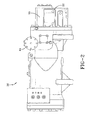
- Screw compressor 38 that may be used as compressor 23 in closed-loop refrigeration system 21 of Figure 1 .
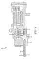
- Figure 3 depicts, in cut-away, some the interior components of screw compressor 38 through the compressor housing.
- Screw compressor 38 includes control panel 22 connected to a power source (not shown in Figure 2 ), which is used to power a motor 43 that drives screw compressor 38.
- the screw compressor 38 includes a lubrication system as one known in the art.
- Lubrication systems include lubricating oils, (usually mineral oils which are completely dehydrated, wax-free and non-foaming), an oil pump to deliver oil under pressure to all bearing surfaces, and an oil separator.
- Screw compressor 38 is in fluid communication with an oil separator (not shown). Refrigerant gas from evaporator 27 and lubricating oil are introduced into the suction side of screw compressor 38 at inlet port 44 to lubricate the rotors of the compressor. A lubricant is also introduced into the screw compressor to lubricate the rotors of the compressor.
- the mixture of high pressure refrigerant gas and lubricating oil is discharged into an oil separator where the mist of lubricating oil in the form of finely divided particles entrained in the refrigerant gas is separated from the refrigerant gas. After separation, the refrigerant gas exits the oil separator through its discharge port 48 and is provided to condenser 25 in the closed loop system 21.
- FIG. 3 the internal mechanisms of the screw compressor 38 can be seen.
- a shaft 50 extending from motor 43 is connected to at least one of a pair of helically-grooved rotors 52.
- One rotor may be stationary or both rotors may be driven by the use of rotor-synchronized timing gears that synchronizes their rotation.
- Refrigerant enters screw compressor 38 through inlet port 44 and is compressed between the lobes of the rotors 52. The compressed gas is discharged into discharge port 48 which is in communication with the downstream condenser 25 in closed loop system 21.
- a plug 54 is positioned within discharge port 48. Although plug 54 is locked into position, it may be unlocked and moved from a first position to a second position.
- Figure 4 is a partial horizontal cross-sectional view of the screw compressor 38 through its center viewed from above, providing a detail view of discharge port 48.
- rotors 52 are not visible, as the view is taken below the rotors. However, this view clearly shows the path taken by refrigerant into discharge port 48.
- Plug 54 is depicted as threaded into discharge port 48 in Figure 4 , although the method of inserting plug 54 into discharge port 48 is not limited to threading, and any other well-known method of assembling and locking plug 54 into a bore may be used. When threading is utilized, plug 54 and discharge port 48 have matching threads. In Figure 4 , plug 54 is shown fully inserted into discharge port 48, providing discharge port with the maximum possible volume.
- Figure 5 is a partial horizontal cross sectional view of the screw compressor 38 through its center viewed from above, providing a detail view of discharge port 48.
- Figure 5 is identical to Figure 4 , except that plug 54 is threaded into discharge port 48 so that the discharge port has a minimum volume.
- plug 54 is threaded to a second position that provides discharge port with a minimum volume and exposed threads 49 of discharge port 48 are visible as plug 54 is not fully threaded into discharge port 48 in Figure 5 .
- Figure 4 and Figure 5 depict plug 54 inserted into discharge port 48 in two positions, a first position in which the discharge port 48 has a maximum volume ( Figure 4 ) and a second position in which the discharge port 48 has a minimum volume ( Figure 5 ), respectively.
- plug 54 may be inserted into discharge port 48 at any position from the first position depicted in Figure 4 to a second position depicted in Figure 5 to provide a variable volume dependent on the location of plug 54 in port 48.
- Plug 54 generally may be fabricated of a relatively dense material, such as steel, so that the inertia of plug 54 within bore 48 is sufficient to prevent movement during operation of screw compressor 38. Additionally, plug 54 has a self locking feature, for example, a spring, a chemical additive, a prevailing torque feature having a deflective or distorted thread type, or any combination thereof.
- the volume ratio V i is the ratio of the suction volume to the discharge volume.
- the suction volume is the volume of the interlobal region before compression.
- the discharge volume is the volume of the meshing rotors just prior to the opening to the discharge port area. Since the discharge port volume 48 is at its maximum due to the position of plug 54, the volume ratio V i for the system is at a minimum. In this position, the operation of the screw compressor 38 and the refrigeration system 21 is most efficient in cooler climates and during cooler months in late autumn, winter and early spring.
- volume ratio V i may also be adjusted, if desired, between the extremes shown in Figures 4 and 5 .
- An intermediate adjustment may be more desirable for seasonal changes and provide improved efficiency for autumn and spring rather than an adjustment selection using one of the extreme positions depicted in either Figures 4 or 5 .
- plug 54 is moved to its second position depicted, in Figure 5 , to provide the discharge port with its minimum volume for warmer climates and/or summer conditions.
- a higher volume ratio V i is required. Higher temperatures require higher operating pressures, and the minimum discharge port volume provides higher pressures.
- the discharge port pressure dictates the downstream pressure at the evaporator.
- the increase in pressure represents an increase in work performed by the compressor 38.
- the increase in work represents an increase in energy usage by the screw compressor 38, but the screw compressor 38 is operated in a more efficient manner.
- V i the volume ratio
- plug 54 is moved to its first position depicted in Figure 4 to provide the discharge port 48 with its maximum volume for cooler climates and/or winter conditions.
- a lower volume ratio V i is required. Cooler ambient temperatures permit lower operating pressures, and the larger discharge port volume provides lower pressures.
- the reduced discharge port pressure decreases the downstream pressure at the evaporator, which in turn provides less cooling capacity.
- the reduction in pressure represents a decrease in work performed by screw compressor 38, which results in increased screw compressor 38 efficiency in cold conditions.
- Discharge port 48 and movable plug 54 are located in the interior of screw compressor 38, as can be seen in Figures 2 and 3 .
- Plug 54 is not readily accessible from the exterior of screw compressor 38.
- compressor cover 33 In order to access plug 54 to move it from a first position to a second position, or any intermediate position, compressor cover 33 must be removed to access the interior of the screw compressor 38.
- screw compressor 38 prior to removing compressor cover 33, screw compressor 38 must be shut down and the pressure within screw compressor 38 must be allowed to equalize to atmospheric pressure and the refrigerant must be removed from the system.
- the screw compressor 38 is isolated from closed loop system 21 and refrigerant must be removed from screw compressor 38. Because this is not a simple procedure and requires shutting screw compressor 38 down, repositioning plug 54 cannot be done on a daily or even a weekly basis. Repositioning of plug 54 is best done on a seasonal or even a semi-annual basis.
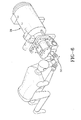
- screw compressor 38 is depicted with cover 33 removed.
- a worker is shown inserting a tool 56 to engage plug 54.
- Tool 56 is inserted into the end of screw compressor 38 and engages the end of plug 54.
- the worker then moves plug 54, such as by rotating it either clockwise or counterclockwise, from a first position to a second position.
- Figure 7 depicts tool 56 being inserted into screw compressor 38 after cover 33 has been removed from screw compressor 38.
- Tool 56 is shown as partially inserted, and the tool head is visible out of contact with plug 54 in discharge port 48, with plug 54 being in first position to provide discharge port 48, plug 54 being in a first position to provide discharge port 48 with its maximum volume.
- Plug 54 is shown in greater detail in Figure 8 a cross-section view, and in Figure 9 a perspective view.
- plug 54 is threaded with external threads while discharge port 48 includes internal threads 49.
- plug 54 may be positioned within discharge port 48 using any other mating method.
- plug 54 may include spring loaded projections that can be aligned into a series of mating apertures at different locations along discharge port 48.
- plug 54 may be slidable from a first position to a second position along discharge port 48, and locked into position by rotating; for example, 90°.
- the exact mechanism used to position plug 54 within discharge port 48 is not critical to the operation of the invention.
- Plug 54 further includes at least one o-ring groove 60 for insertion of an o-ring.
- O-rings consist of neoprene, chloroprene, and other fluid-resistant elastomeric compounds. Positioning an o-ring in this groove when assembled into discharge port 48 prevents leakage of refrigerant around plug 54. Additionally, seals to prevent leakage of refrigerant for use in combination with plug 54 include compression seals, mechanical seals, and the like.
- the position of plug 54 within discharge port 48 can be determined by any convenient method. For example, the total number rotations that plug 54 can make within discharge port 48 is known. When plug 54 is fully inserted into discharge port 48 as shown in Figure 4 , discharge port 48 has a maximum volume suitable for summer conditions and plug 54 is at maximum travel within discharge port 48 (i.e. fully inserted). The number of rotations required to move plug 54 from the position shown in Figure 4 to the position shown in Figure 5 is known or can be determined, and the worker can count the number of rotations when changing the position of plug 54. A position of the plug 54 for autumn or spring conditions can also be determined on the basis of rotations from hot or warm positions.
- screw compressor 38 and plug 54 include index lines or marks adjacent to the aperture wherein tool 56 is inserted to interface with plug 54.
- the index lines can be related to the position of the plug within the aperture, which can be related to the discharge port volume.
- tool 56 includes a series of scribe lines which can be matched to the index line, each scribe line corresponding to a position of the plug 54 for a particular season.
- tool 56 may be provided in different lengths, each length corresponding to a different season, corresponding to a desired location of plug 54.
- Plug 54 first may be moved o the position shown in Figure 4 and then the appropriate tool can be inserted to move plug 54 to its proper position.
- plug 54 includes a feature that mates with a corresponding feature on tool 56. As shown in Figures 8 and 9 , this feature is by way of example, but not limited to, a hex shaped aperture 62 on plug 54, and tool 56 includes, a corresponding hex-shaped head, that can be inserted into the aperture on plug 54.
- the shapes are not limited and any other shape may be used.
- the head and aperture may be reversed so that plug 54 includes the head and tool 56 includes the aperture. Any other configuration for mating tool 56 to plug 54 to facilitate movement of plug 54 within discharge port 48 may be used.
- a screw compressor 38 may be fabricated for use in cold climates or warm climates.
- the volume ratio V i of the screw compressor 38 can be adjusted manually to provide the volume ratio V i most suitable for the climate in which the screw compressor 38 is used.
- a screw compressor 38 having a manually variable volume ratio V i can be adjusted seasonally to provide screw compressor 38 with the volume ratio V i most suitable for the season, while also providing improved efficiency.
Landscapes
- Engineering & Computer Science (AREA)
- Mechanical Engineering (AREA)
- General Engineering & Computer Science (AREA)
- Physics & Mathematics (AREA)
- Fluid Mechanics (AREA)
- Applications Or Details Of Rotary Compressors (AREA)
Description
- This application is directed to screw compressors. More particularly, the present invention is directed to screw compressors having a variable volume capacity.
- In positive-displacement compressors, capacity control may be obtained by both speed modulation and suction throttling to reduce the volume of vapor or gas drawn into a compressor. Capacity control for a compressor can provide continuous modulation from 100% capacity to less than 10% capacity, good part-load efficiency, unloaded starting, and unchanged reliability. In some positive-displacement compressors, capacity can also be controlled by a slide valve employed in the compressor. The slide valve can be operated to remove a portion of the vapor from the compression chamber of the compressor, thereby controlling the capacity of the compressor. Besides the slide valve, other mechanical devices, such as slot valves and lift valves, may be employed in positive-displacement compressors to control capacity. Adjustments to capacity control valves or variable displacement mechanisms can meet the demands of the system. In a refrigeration system, capacity can be regulated based upon a temperature set point for the space being cooled. In other systems where the compressor is processing gas, capacity may be regulated to fully load the torque generator or prime mover (turbine or engine drive) for the compressor. However, all of the currently available methods are expensive and add to the initial cost of investment in the equipment.
- In chiller applications where economy is desired both in the initial cost of the system and in operation of the system, a variable volume ratio application is desired. Volume ratio (Vi,) is the ratio of the volume of a groove at the start of compression to the discharge volume when the discharge port begins to open. Hence, the volume ratio is determined by the size and shape of the discharge port, since the groove volume is a fixed volume at the start of compression.
- For maximum efficiency, the pressure generated within the grooves during compression should exactly equal the pressure in the discharge volume when the discharge port begins to open. If this is not the case, either overcompression or undercompression occurs, both resulting in internal efficiency losses. Furthermore, overcompression can harm the compressor. Such losses increase power consumption and noise, while reducing efficiency. Volume ratio selection should be made according to operating conditions.
- One solution is set out in
US Publication 2012/227437 for locations in which operating conditions frequently change. This solution provides additional penetrations in the housing with members located in the penetrations, The position of the members in the penetration(s) vary the flow path from the meshed helical lobed rotor to the discharge port through apertures in the penetration(s), effectively modifying the discharge volume by extending the flow path. This solution allows for frequent modification of the flow path by changing the position of the members in the penetration(s) without having to shut the system down to accomplish the modification. - If the operating conditions of the system seldom change, it is possible to specify a fixed-volume ratio compressor that will provide good efficiency. Because overcompression can damage a compressor, a compressor is designed so that it does not frequently operate in an overcompression mode. As a result, such a compressor is designed to run at maximum compression under the most severe operating conditions, meaning that such a compressor runs in undercompression modes as service conditions dictate operation in maximum compression mode. What is needed is a system that permits adjustments to the volume ratio that changes the volume ratio depending on the conditions that the compressor experiences. This will allow the compressor volume to be adjusted to change the volume, and hence the volume ratio, as operating conditions change, allowing the compressor to operate at maximum efficiency. A variable volume ratio screw compressor that meets one or more of the above needs would be desirable in the art.
- A variable volume ratio screw compressor that meets one or more of the above needs would be desirable in the art.
- A screw compressor for use in a refrigeration system is provided. The screw compressor has a variable capacity and includes a motor connected to a power source. A control panel controls operation of the compressor, including the motor and power source. The screw compressor has a variable volume capability. The screw compressor comprises a pair of meshing helical lobed rotors rotating within a housing, the rotating rotors being driven by a drive shaft connected to the motor. The housing encloses the rotors or screws, which operate in a working chamber located within the housing.
- Refrigerant gas enters the compressor inlet from the suction or low pressure side of the refrigerant circuit through an inlet port when the rotors are arranged in the chamber to maximum length. The space between the lobes of the rotors, the interlobe region, is filled with refrigerant and the inlet port is closed. The refrigerant is compressed between the rotors in the interlobe region as the rotors rotate with respect to one another, compressing the refrigerant gas and raising its pressure. The highly compressed gas is ejected from the rotor interlobe region as a high pressure gas, which is expelled into a discharge port in fluid communication with the refrigeration circuit.
- The volume ratio is a measure of the efficiency of operation of a positive displacement compressor. The present invention permits efficiency of operation of a compressor to change with climate, which may be naturally variable with seasons. The volume ratio is determined by the size and shape of the discharge port. The volume associated with the discharge port, referred to as the discharge port volume, can be periodically varied in the present invention, also allowing the efficiency of the compressor to be varied periodically. The efficiency of a variable capacity screw compressor is determined by the position of a plug in the discharge port and by ambient temperature.
- The discharge port volume includes a penetration that houses a movable member or plug. The movable plug or member allows the discharge port volume to be varied. This movable member is accessible from the exterior of the compressor housing when the compressor is shut down. The movable member can be accessed from the exterior of the housing to adjust position of the movable member within the discharge port volume. The movable member may be adjusted to a full open position in which the discharge port volume is maximized, to a full closed position in which the discharge port volume is minimized and to any intermediate position between full open and full closed. By adjusting the position of the movable member from one position to another, the volume in the discharge port can be modified, thereby modifying the volume ratio of the compressor, even as all other operating parameters remain constant.
- An advantage of a screw compressor of variable volume having a volume adjustment mechanism is that a machine can be manufactured and the volume ratio periodically can be adjusted to maximize efficiency based on the climate of the area in which it is used with minimal disassembly of the compressor after shipment.
- Another advantage of a screw compressor having a volume adjustment mechanism is that a machine can be procured based on a maximum volume ratio for the most severe conditions, but the volume ratio can be adjusted based on seasonal variations by using the volume adjustment feature with minimal disassembly of the compressor so that undercompression can be avoided when conditions are not severe.
- In one embodiment, a variable capacity screw compressor, having a volume ratio adjustment mechanism, can be manufactured and the volume ratio periodically adjusted to maximize efficiency based on the climate of the area in which the compressor is used with minimal disassembly of the compressor.
- In another embodiment, a variable capacity screw compressor having a volume ratio adjustment mechanism can be procured based on a maximum volume ratio for the most severe conditions. The volume ratio can be adjusted based on seasonal variations so that undercompression is avoided when conditions are not severe.
- Other features and advantages of the present invention will be apparent from the following more detailed description of the preferred embodiment, taken in conjunction with the accompanying drawings which illustrate, by way of example, the principles of the invention.
-
-
Figure 1 depicts a refrigeration cycle. -
Figure 2 schematically illustrates a typical screw compressor used in the refrigeration cycle ofclaim 1. -
Figure 3 depicts the screw compressor ofFigure 2 showing the interior components of the screw compressor through the housing, the view further showing the discharge port with a plug in the discharge port. -
Figure 4 depicts a partial horizontal cross sectional view of the screw compressor through its center, viewed from above, providing a detail view of the discharge port, viewed from above, with the movable plug positioned in the discharge port to provide it with maximum volume. -
Figure 5 depicts a partial horizontal cross sectional view of the screw compressor through its center, viewed from above, providing a detail view of the discharge port, viewed from above, with the movable plug positioned in the discharge port to provide it with minimum volume. -
Figure 6 depicts a worker inserting a tool into the screw compressor to modify the location of the movable plug within the discharge port. -
Figure 7 depicts the compressor in cross section, with the cover removed, showing the tool partially inserted into the compressor. -
Figure 8 depicts the plug ofFigure 7 in cross section. -
Figure 9 is a perspective view of the plug ofFigure 8 . - Provided is an exemplary variable capacity screw compressor for use in a refrigeration system. A volume ratio adjustment mechanism allows the volume ratio to be adjusted based on seasonal variations thus improving efficiency so that undercompression is avoided.
- Referring to
Fig. 1 , an exemplary refrigeration cycle is shown. The refrigeration cycle is aclosed loop system 21 in which refrigerant, the working fluid, is compressed by apositive displacement compressor 23 that increases the pressure of the refrigerant gas.Compressor 23 is driven by apower source 10 that is controlled by acontrol panel 22. The high pressure refrigerant fromcompressor 23 is discharged through a compressor discharge port which is in fluid communication with acondenser 25 that condenses the high pressure gas into a pressurized fluid. In one embodiment,compressor 23 is a screw type. Alternatively,compressor 23 is a reciprocating, rotary, scroll, or centrifugal type compressor. -
Condenser 25 is in heat exchange communication with a first heat transfer medium that removes heat of condensation resulting from the change of state of refrigerant from hot, high pressure gas to liquid. This heat transfer medium may be the atmosphere (air of forced air) or a liquid, preferably water. The various ways of removing this heat are well know and do not contribute to the inventive nature of this invention. The condensed fluid fromcondenser 25 is in fluid communication with anexpansion valve 31 that expands at least some of the pressurized fluid into a gas as it flows within closedloop system 21. Theclosed loop system 21 from thedischarge port 48 ofcompressor 23 to theexpansion valve 31 is termed the high pressure side of the refrigeration system orcircuit 21. - After the refrigerant passes through
expansion valve 31 as a mixture of gas and liquid, its pressure is reduced.Evaporator 27 receives the refrigerant fromexpansion valve 31.Evaporator 27 is in heat exchange communication with a second heat transfer medium. The heat of absorption is absorbed by the refrigerant inevaporator 27 from the second heat transfer medium, as the liquid refrigerant undergoes a change of state to a vapor. As this heat is absorbed, the heat transfer medium is cooled. The heat transfer medium may be used directly to cool or refrigerate an area, for example when the heat transfer medium is air, or it may be used to cool a liquid, such as water and conveyed to another heat transfer device in an area or room, such as in water cooled chiller applications. In such applications, the chilled water is sent to the chiller and then set o heat transfer devices in separate areas of a building on demand. The refrigerant gas fromevaporator 27 is then returned to the suction side ofcompressor 23 to complete the circuit.Closed loop system 21 immediately afterexpansion valve 31 to the suction side ofcompressor 23 is termed the low pressure side of the system circuit. - Referring to
Figures 2 and3 , there is depicted ascrew compressor 38 that may be used ascompressor 23 in closed-loop refrigeration system 21 ofFigure 1 .Figure 3 depicts, in cut-away, some the interior components ofscrew compressor 38 through the compressor housing.Screw compressor 38 includescontrol panel 22 connected to a power source (not shown inFigure 2 ), which is used to power amotor 43 that drivesscrew compressor 38. Although not shown, thescrew compressor 38 includes a lubrication system as one known in the art. Lubrication systems include lubricating oils, (usually mineral oils which are completely dehydrated, wax-free and non-foaming), an oil pump to deliver oil under pressure to all bearing surfaces, and an oil separator. Oil is separated from the refrigerant gas as the refrigerant gas exits the high pressure side of the compressor. Oil is then returned to the low pressure side of the compressor to seal the clearance between the rotors, and between the rotors and the cylinder.Screw compressor 38 is in fluid communication with an oil separator (not shown). Refrigerant gas fromevaporator 27 and lubricating oil are introduced into the suction side ofscrew compressor 38 atinlet port 44 to lubricate the rotors of the compressor. A lubricant is also introduced into the screw compressor to lubricate the rotors of the compressor. Once compressed withinscrew compressor 38, the mixture of high pressure refrigerant gas and lubricating oil is discharged into an oil separator where the mist of lubricating oil in the form of finely divided particles entrained in the refrigerant gas is separated from the refrigerant gas. After separation, the refrigerant gas exits the oil separator through itsdischarge port 48 and is provided tocondenser 25 in theclosed loop system 21. - In
Figure 3 , the internal mechanisms of thescrew compressor 38 can be seen. Ashaft 50 extending frommotor 43 is connected to at least one of a pair of helically-groovedrotors 52. One rotor may be stationary or both rotors may be driven by the use of rotor-synchronized timing gears that synchronizes their rotation. Refrigerant entersscrew compressor 38 throughinlet port 44 and is compressed between the lobes of therotors 52. The compressed gas is discharged intodischarge port 48 which is in communication with thedownstream condenser 25 inclosed loop system 21. As can be seen inFigure 3 , aplug 54 is positioned withindischarge port 48. Althoughplug 54 is locked into position, it may be unlocked and moved from a first position to a second position. -
Figure 4 is a partial horizontal cross-sectional view of thescrew compressor 38 through its center viewed from above, providing a detail view ofdischarge port 48. InFigure 4 ,rotors 52 are not visible, as the view is taken below the rotors. However, this view clearly shows the path taken by refrigerant intodischarge port 48.Plug 54 is depicted as threaded intodischarge port 48 inFigure 4 , although the method of insertingplug 54 intodischarge port 48 is not limited to threading, and any other well-known method of assembling and lockingplug 54 into a bore may be used. When threading is utilized, plug 54 anddischarge port 48 have matching threads. InFigure 4 , plug 54 is shown fully inserted intodischarge port 48, providing discharge port with the maximum possible volume. -
Figure 5 is a partial horizontal cross sectional view of thescrew compressor 38 through its center viewed from above, providing a detail view ofdischarge port 48.Figure 5 is identical toFigure 4 , except thatplug 54 is threaded intodischarge port 48 so that the discharge port has a minimum volume. As shown inFigure 5 , plug 54 is threaded to a second position that provides discharge port with a minimum volume and exposedthreads 49 ofdischarge port 48 are visible asplug 54 is not fully threaded intodischarge port 48 inFigure 5 . -
Figure 4 and Figure 5 depictplug 54 inserted intodischarge port 48 in two positions, a first position in which thedischarge port 48 has a maximum volume (Figure 4 ) and a second position in which thedischarge port 48 has a minimum volume (Figure 5 ), respectively. It will be understood by those skilled in the art, that plug 54 may be inserted intodischarge port 48 at any position from the first position depicted inFigure 4 to a second position depicted inFigure 5 to provide a variable volume dependent on the location ofplug 54 inport 48.Plug 54 generally may be fabricated of a relatively dense material, such as steel, so that the inertia ofplug 54 withinbore 48 is sufficient to prevent movement during operation ofscrew compressor 38. Additionally, plug 54 has a self locking feature, for example, a spring, a chemical additive, a prevailing torque feature having a deflective or distorted thread type, or any combination thereof. - As previously noted, volume ratio Vi is related to the discharge volume. More specifically, the volume ratio is provided as:

where - Vi is the volume ratio
- ∈ is compression ratio and
- K is a refrigerant constant. For refrigerant 134A, K is 1.8.
- When
plug 54 is in its first position, as shown inFigure 4 , in which discharge port has its maximum volume, high pressure refrigerant gas is discharged from compressor lobes intodischarge port 48 and achieves its minimum volume ratio. The volume ratio Vi is the ratio of the suction volume to the discharge volume. In this first position, the suction volume is the volume of the interlobal region before compression. The discharge volume is the volume of the meshing rotors just prior to the opening to the discharge port area. Since thedischarge port volume 48 is at its maximum due to the position ofplug 54, the volume ratio Vi for the system is at a minimum. In this position, the operation of thescrew compressor 38 and therefrigeration system 21 is most efficient in cooler climates and during cooler months in late autumn, winter and early spring. - When
plug 54 is in its second position, as shown inFigure 5 , in which dischargeport 48 has its minimum volume, high pressure refrigerant gas is discharged into thedischarge port 48 and achieves its maximum compression ratio. The volume ratio Vi is the ratio of the suction volume to the discharge volume. In this second position, the suction volume is the volume of the interlobal region before compression. The discharge volume is the volume of the meshing rotors just prior to the opening to the discharge port area. Since the volume of thedischarge port 48 is at its minimum, the volume ratio Vi for the system is at a maximum. In this position, the operation of thescrew compressor 38 and the system is most efficient in warmer climates or during warmer months in late spring, summer, and early autumn. - It will also be recognized by those skilled in the art that the volume ratio Vi may also be adjusted, if desired, between the extremes shown in
Figures 4 and 5 . An intermediate adjustment may be more desirable for seasonal changes and provide improved efficiency for autumn and spring rather than an adjustment selection using one of the extreme positions depicted in eitherFigures 4 or 5 . - In operation, plug 54 is moved to its second position depicted, in
Figure 5 , to provide the discharge port with its minimum volume for warmer climates and/or summer conditions. In a season in which warmer weather is expected or wherein the compressor is in a system located in a warmer climate, a higher volume ratio Vi is required. Higher temperatures require higher operating pressures, and the minimum discharge port volume provides higher pressures. The discharge port pressure dictates the downstream pressure at the evaporator. The increase in pressure represents an increase in work performed by thecompressor 38. The increase in work represents an increase in energy usage by thescrew compressor 38, but thescrew compressor 38 is operated in a more efficient manner. In one embodiment, by matching the volume ratio Vi to the season or the climate, not only is the compressor operated more efficiently, but noise fromscrew compressor 38 operations is also reduced. - In operation, plug 54 is moved to its first position depicted in
Figure 4 to provide thedischarge port 48 with its maximum volume for cooler climates and/or winter conditions. In a season in which cooler weather is expected or wherein thescrew compressor 38 is in a system located in a cool climate, a lower volume ratio Vi is required. Cooler ambient temperatures permit lower operating pressures, and the larger discharge port volume provides lower pressures. The reduced discharge port pressure decreases the downstream pressure at the evaporator, which in turn provides less cooling capacity. In one embodiment, the reduction in pressure represents a decrease in work performed byscrew compressor 38, which results in increasedscrew compressor 38 efficiency in cold conditions. -
Discharge port 48 andmovable plug 54 are located in the interior ofscrew compressor 38, as can be seen inFigures 2 and3 .Plug 54 is not readily accessible from the exterior ofscrew compressor 38. In order to accessplug 54 to move it from a first position to a second position, or any intermediate position, compressor cover 33 must be removed to access the interior of thescrew compressor 38. In one embodiment, prior to removingcompressor cover 33,screw compressor 38 must be shut down and the pressure withinscrew compressor 38 must be allowed to equalize to atmospheric pressure and the refrigerant must be removed from the system. In another embodiment, thescrew compressor 38 is isolated fromclosed loop system 21 and refrigerant must be removed fromscrew compressor 38. Because this is not a simple procedure and requires shuttingscrew compressor 38 down, repositioningplug 54 cannot be done on a daily or even a weekly basis. Repositioning ofplug 54 is best done on a seasonal or even a semi-annual basis. - Referring now to
Figure 6 , screwcompressor 38 is depicted withcover 33 removed. A worker is shown inserting atool 56 to engageplug 54.Tool 56 is inserted into the end ofscrew compressor 38 and engages the end ofplug 54. The worker then movesplug 54, such as by rotating it either clockwise or counterclockwise, from a first position to a second position.Figure 7 depictstool 56 being inserted intoscrew compressor 38 aftercover 33 has been removed fromscrew compressor 38.Tool 56 is shown as partially inserted, and the tool head is visible out of contact withplug 54 indischarge port 48, withplug 54 being in first position to providedischarge port 48, plug 54 being in a first position to providedischarge port 48 with its maximum volume. -
Plug 54 is shown in greater detail inFigure 8 a cross-section view, and inFigure 9 a perspective view. In a preferred embodiment as shown inFigure 8 , plug 54 is threaded with external threads whiledischarge port 48 includesinternal threads 49. However, plug 54 may be positioned withindischarge port 48 using any other mating method. For example, plug 54 may include spring loaded projections that can be aligned into a series of mating apertures at different locations alongdischarge port 48. Alternatively, plug 54 may be slidable from a first position to a second position alongdischarge port 48, and locked into position by rotating; for example, 90°. The exact mechanism used to position plug 54 withindischarge port 48 is not critical to the operation of the invention.Plug 54 further includes at least one o-ring groove 60 for insertion of an o-ring. O-rings consist of neoprene, chloroprene, and other fluid-resistant elastomeric compounds. Positioning an o-ring in this groove when assembled intodischarge port 48 prevents leakage of refrigerant aroundplug 54. Additionally, seals to prevent leakage of refrigerant for use in combination withplug 54 include compression seals, mechanical seals, and the like. - The position of
plug 54 withindischarge port 48 can be determined by any convenient method. For example, the total number rotations that plug 54 can make withindischarge port 48 is known. Whenplug 54 is fully inserted intodischarge port 48 as shown inFigure 4 , dischargeport 48 has a maximum volume suitable for summer conditions and plug 54 is at maximum travel within discharge port 48 (i.e. fully inserted). The number of rotations required to moveplug 54 from the position shown inFigure 4 to the position shown inFigure 5 is known or can be determined, and the worker can count the number of rotations when changing the position ofplug 54. A position of theplug 54 for autumn or spring conditions can also be determined on the basis of rotations from hot or warm positions. In another embodiment,screw compressor 38 and plug 54 include index lines or marks adjacent to the aperture whereintool 56 is inserted to interface withplug 54. The index lines can be related to the position of the plug within the aperture, which can be related to the discharge port volume. In yet another embodiment,tool 56 includes a series of scribe lines which can be matched to the index line, each scribe line corresponding to a position of theplug 54 for a particular season. In another embodiment,tool 56 may be provided in different lengths, each length corresponding to a different season, corresponding to a desired location ofplug 54.Plug 54 first may be moved o the position shown inFigure 4 and then the appropriate tool can be inserted to moveplug 54 to its proper position. - In one embodiment, plug 54 includes a feature that mates with a corresponding feature on
tool 56. As shown inFigures 8 and 9 , this feature is by way of example, but not limited to, a hex shapedaperture 62 onplug 54, andtool 56 includes, a corresponding hex-shaped head, that can be inserted into the aperture onplug 54. The shapes are not limited and any other shape may be used. In addition, the head and aperture may be reversed so thatplug 54 includes the head andtool 56 includes the aperture. Any other configuration formating tool 56 to plug 54 to facilitate movement ofplug 54 withindischarge port 48 may be used. - By use of a discharge port, such as
discharge port 48 with aplug 54 to provide a variable volume discharge port, ascrew compressor 38 may be fabricated for use in cold climates or warm climates. The volume ratio Vi of thescrew compressor 38 can be adjusted manually to provide the volume ratio Vi most suitable for the climate in which thescrew compressor 38 is used. Additionally, ascrew compressor 38 having a manually variable volume ratio Vi can be adjusted seasonally to providescrew compressor 38 with the volume ratio Vi most suitable for the season, while also providing improved efficiency. - While the invention has been described with reference to a preferred embodiment, it will be understood by those skilled in the art that various changes may be made and equivalents may be substituted for elements thereof without departing from the scope of the invention. In addition, many modifications may be made to adapt a particular situation or material to the teachings of the invention without departing from the essential scope thereof. Therefore, it is intended that the invention not be limited to the particular embodiment disclosed as the best mode contemplated for carrying out this invention, but that the invention will include all embodiments falling within the scope of the appended claims.
Claims (15)
- A variable efficiency refrigeration system (21) having a variable efficiency screw compressor (38) with an inlet port (44) to draw a refrigerant into the compressor, a pair of helically grooved rotors (52) in fluid communication with the inlet port to compress the refrigerant from a first low pressure to a second higher pressure, a discharge port (48) in fluid communication with a rotating rotor that receives the refrigerant at the second higher pressure and discharge the refrigerant, a power source powering the compressor, the system further including a control panel (22) modulating the power source, a condenser (25) in fluid communication with the compressor that condenses the pressurized refrigerant gas to a pressurized liquid, an evaporator (27) in fluid communication with the condenser and with the compressor, an expansion valve (31) positioned between the condenser and the evaporator, wherein the expansion valve receives condensed pressurized refrigerant liquid and expands it to a lower pressure mist of gas and liquid for the evaporator, characterized by:a plug (54) positioned with the discharge port (48) and movable within the discharge port (48) from a first position to a second position, the plug (54) providing the discharge port (48) with a variable volume, in which the volume is at a maximum in the first position and in which the volume is at a minimum in the second position, the plug (54) being movable to any position between the first position and the second position to provide an intermediate volume.
- The refrigeration system of claim 1, wherein efficiency of the compressor (38) is determined by the volume of the discharge port (48), which is determined by the position of the plug (54) in the discharge port (48), and by seasonal ambient temperature.
- The refrigeration system of claim 1, wherein the plug (54) is accessible from the exterior of the compressor (38) so that the plug can be moved to provide the compressor (38) with the variable volume.
- The refrigeration system of claim 1, wherein the plug (54) is accessible from the exterior of the compressor (38) when the compressor is shut down.
- The refrigeration system of claim 1, wherein the discharge port (48) includes a threaded bore (49) and the plug (54) includes mating threads, the plug being positioned within the bore.
- The refrigeration system of claim 1, wherein the ambient temperature is the seasonal average ambient temperature experienced in a geographic location.
- The refrigeration system of claim 1, wherein a volume ratio determined by a volume of lobes in the helically-grooved rotors (52) to the volume of the discharge port (48) is adjusted by adjusting the plug position based on seasonal average ambient temperature to avoid undercompression.
- The refrigeration system of claim 1, wherein efficiency of the compressor is increased in cold ambient conditions.
- The refrigeration system of claim 1, wherein increased efficiency of the compressor (38) further includes reduced noise from the compressor (38).
- The refrigeration system of claim 1, wherein the compressor (38) and plug (54) include index marks to position the plug into a desired position.
- The refrigeration system of claim 1, wherein the plug (54) has a feature that mates with a corresponding feature on an adjusting tool.
- The refrigeration system of claim 1, further including water in heat exchange communication with the evaporator (27), the water after being cooled by the evaporator (27) being provided to a chiller, wherein the chilled water from the chiller can be used to cool a remote area.
- The refrigeration system of claim 1, further including a heat transfer medium in heat exchange communication with the evaporator (27), wherein the heat transfer medium cooled by the evaporator, cools an immediate area.
- The refrigeration system of claim 1, wherein the refrigeration system is a closed loop system.
- The refrigeration system of claim 1 wherein the compressor (38) is manufactured and the volume ratio is adjusted to maximize efficiency based on the climate of a geographic area in which the compressor is used.
Applications Claiming Priority (2)
| Application Number | Priority Date | Filing Date | Title |
|---|---|---|---|
| US13/649,405 US9032750B2 (en) | 2011-10-18 | 2012-10-11 | Manual Vi adjustment mechanism for screw compressors |
| PCT/US2013/036553 WO2014058477A1 (en) | 2012-10-11 | 2013-04-15 | MANUAL Vi ADJUSTMENT MECHANISM FOR SCREW COMPRESSORS |
Publications (2)
| Publication Number | Publication Date |
|---|---|
| EP2758669A1 EP2758669A1 (en) | 2014-07-30 |
| EP2758669B1 true EP2758669B1 (en) | 2015-06-24 |
Family
ID=48225127
Family Applications (1)
| Application Number | Title | Priority Date | Filing Date |
|---|---|---|---|
| EP13719335.5A Active EP2758669B1 (en) | 2012-10-11 | 2013-04-15 | MANUAL Vi ADJUSTMENT MECHANISM FOR SCREW COMPRESSORS |
Country Status (3)
| Country | Link |
|---|---|
| EP (1) | EP2758669B1 (en) |
| CN (1) | CN103857915B (en) |
| WO (1) | WO2014058477A1 (en) |
Families Citing this family (2)
| Publication number | Priority date | Publication date | Assignee | Title |
|---|---|---|---|---|
| US10677246B2 (en) * | 2016-07-18 | 2020-06-09 | Johnson Controls Technology Company | Variable volume ratio compressor |
| CN110410329B (en) * | 2019-08-26 | 2025-06-27 | 珠海格力电器股份有限公司 | Compressor and air conditioner |
Family Cites Families (5)
| Publication number | Priority date | Publication date | Assignee | Title |
|---|---|---|---|---|
| SE451394B (en) * | 1986-01-31 | 1987-10-05 | Stal Refrigeration Ab | PROCEDURE FOR REGULATING A ROTATING COMPRESSOR |
| JPH02146288A (en) * | 1988-11-25 | 1990-06-05 | Ebara Corp | Displacement type compressor with internal compression |
| EP2304241B1 (en) * | 2008-06-24 | 2016-04-27 | Carrier Corporation | Automatic volume ratio variation for a rotary screw compressor |
| CN103097734B (en) * | 2010-09-14 | 2016-03-23 | 江森自控科技公司 | Compressor and the method for controlling the volume ratio of compressor |
| US9631620B2 (en) * | 2011-03-11 | 2017-04-25 | Johnson Controls Technology Company | Stationary volume ratio adjustment mechanism |
-
2013
- 2013-04-15 CN CN201380001478.XA patent/CN103857915B/en active Active
- 2013-04-15 WO PCT/US2013/036553 patent/WO2014058477A1/en not_active Ceased
- 2013-04-15 EP EP13719335.5A patent/EP2758669B1/en active Active
Also Published As
| Publication number | Publication date |
|---|---|
| CN103857915A (en) | 2014-06-11 |
| EP2758669A1 (en) | 2014-07-30 |
| CN103857915B (en) | 2016-01-20 |
| WO2014058477A1 (en) | 2014-04-17 |
Similar Documents
| Publication | Publication Date | Title |
|---|---|---|
| US9032750B2 (en) | Manual Vi adjustment mechanism for screw compressors | |
| CN104047853B (en) | Stepless variable volume ratio in the screw compressor of use ratio valve control | |
| US7914267B2 (en) | Multistage compressor for a CO2 cycle that includes a rotary compressing mechanism and a scroll compressing mechanism | |
| US7647790B2 (en) | Injection system and method for refrigeration system compressor | |
| US8769982B2 (en) | Injection system and method for refrigeration system compressor | |
| US8899942B2 (en) | Volume ratio control system and method | |
| EP2411677B1 (en) | Compressor with a bypass port | |
| KR20090052793A (en) | Refrigeration Units and Compressors | |
| KR880700169A (en) | Refrigeration plant and rotary positive displacement machine | |
| US9631620B2 (en) | Stationary volume ratio adjustment mechanism | |
| WO2017130401A1 (en) | Scroll compressor and heat pump device | |
| EP2758669A1 (en) | MANUAL Vi ADJUSTMENT MECHANISM FOR SCREW COMPRESSORS | |
| US8272846B2 (en) | Integral slide valve relief valve | |
| EP3350448B1 (en) | Intermediate discharge port for a compressor | |
| KR101330332B1 (en) | Two-stage screw compression type refrigerating device | |
| US10619635B2 (en) | Scallop step for a scroll compressor | |
| CN112012916B (en) | Piston type variable-frequency and variable-capacity refrigeration compressor | |
| JP4991255B2 (en) | Refrigeration cycle equipment | |
| CN112012917A (en) | Compressor variable volume structure with drainage groove | |
| US20190113037A1 (en) | Oil circulation in a scroll compressor | |
| HK1138050B (en) | Integral slide valve relief valve | |
| JP2019027412A (en) | Hermetic compressor |
Legal Events
| Date | Code | Title | Description |
|---|---|---|---|
| PUAI | Public reference made under article 153(3) epc to a published international application that has entered the european phase |
Free format text: ORIGINAL CODE: 0009012 |
|
| 17P | Request for examination filed |
Effective date: 20140417 |
|
| AK | Designated contracting states |
Kind code of ref document: A1 Designated state(s): AL AT BE BG CH CY CZ DE DK EE ES FI FR GB GR HR HU IE IS IT LI LT LU LV MC MK MT NL NO PL PT RO RS SE SI SK SM TR |
|
| GRAP | Despatch of communication of intention to grant a patent |
Free format text: ORIGINAL CODE: EPIDOSNIGR1 |
|
| DAX | Request for extension of the european patent (deleted) | ||
| INTG | Intention to grant announced |
Effective date: 20150310 |
|
| GRAS | Grant fee paid |
Free format text: ORIGINAL CODE: EPIDOSNIGR3 |
|
| GRAA | (expected) grant |
Free format text: ORIGINAL CODE: 0009210 |
|
| AK | Designated contracting states |
Kind code of ref document: B1 Designated state(s): AL AT BE BG CH CY CZ DE DK EE ES FI FR GB GR HR HU IE IS IT LI LT LU LV MC MK MT NL NO PL PT RO RS SE SI SK SM TR |
|
| REG | Reference to a national code |
Ref country code: GB Ref legal event code: FG4D |
|
| REG | Reference to a national code |
Ref country code: CH Ref legal event code: EP |
|
| REG | Reference to a national code |
Ref country code: AT Ref legal event code: REF Ref document number: 733032 Country of ref document: AT Kind code of ref document: T Effective date: 20150715 |
|
| REG | Reference to a national code |
Ref country code: IE Ref legal event code: FG4D |
|
| REG | Reference to a national code |
Ref country code: DE Ref legal event code: R096 Ref document number: 602013002087 Country of ref document: DE |
|
| PG25 | Lapsed in a contracting state [announced via postgrant information from national office to epo] |
Ref country code: NO Free format text: LAPSE BECAUSE OF FAILURE TO SUBMIT A TRANSLATION OF THE DESCRIPTION OR TO PAY THE FEE WITHIN THE PRESCRIBED TIME-LIMIT Effective date: 20150924 Ref country code: LT Free format text: LAPSE BECAUSE OF FAILURE TO SUBMIT A TRANSLATION OF THE DESCRIPTION OR TO PAY THE FEE WITHIN THE PRESCRIBED TIME-LIMIT Effective date: 20150624 Ref country code: FI Free format text: LAPSE BECAUSE OF FAILURE TO SUBMIT A TRANSLATION OF THE DESCRIPTION OR TO PAY THE FEE WITHIN THE PRESCRIBED TIME-LIMIT Effective date: 20150624 Ref country code: HR Free format text: LAPSE BECAUSE OF FAILURE TO SUBMIT A TRANSLATION OF THE DESCRIPTION OR TO PAY THE FEE WITHIN THE PRESCRIBED TIME-LIMIT Effective date: 20150624 |
|
| REG | Reference to a national code |
Ref country code: AT Ref legal event code: MK05 Ref document number: 733032 Country of ref document: AT Kind code of ref document: T Effective date: 20150624 |
|
| REG | Reference to a national code |
Ref country code: LT Ref legal event code: MG4D |
|
| PG25 | Lapsed in a contracting state [announced via postgrant information from national office to epo] |
Ref country code: BG Free format text: LAPSE BECAUSE OF FAILURE TO SUBMIT A TRANSLATION OF THE DESCRIPTION OR TO PAY THE FEE WITHIN THE PRESCRIBED TIME-LIMIT Effective date: 20150924 Ref country code: LV Free format text: LAPSE BECAUSE OF FAILURE TO SUBMIT A TRANSLATION OF THE DESCRIPTION OR TO PAY THE FEE WITHIN THE PRESCRIBED TIME-LIMIT Effective date: 20150624 Ref country code: RS Free format text: LAPSE BECAUSE OF FAILURE TO SUBMIT A TRANSLATION OF THE DESCRIPTION OR TO PAY THE FEE WITHIN THE PRESCRIBED TIME-LIMIT Effective date: 20150624 Ref country code: GR Free format text: LAPSE BECAUSE OF FAILURE TO SUBMIT A TRANSLATION OF THE DESCRIPTION OR TO PAY THE FEE WITHIN THE PRESCRIBED TIME-LIMIT Effective date: 20150925 |
|
| REG | Reference to a national code |
Ref country code: NL Ref legal event code: MP Effective date: 20150624 |
|
| PG25 | Lapsed in a contracting state [announced via postgrant information from national office to epo] |
Ref country code: EE Free format text: LAPSE BECAUSE OF FAILURE TO SUBMIT A TRANSLATION OF THE DESCRIPTION OR TO PAY THE FEE WITHIN THE PRESCRIBED TIME-LIMIT Effective date: 20150624 |
|
| PG25 | Lapsed in a contracting state [announced via postgrant information from national office to epo] |
Ref country code: CZ Free format text: LAPSE BECAUSE OF FAILURE TO SUBMIT A TRANSLATION OF THE DESCRIPTION OR TO PAY THE FEE WITHIN THE PRESCRIBED TIME-LIMIT Effective date: 20150624 Ref country code: AT Free format text: LAPSE BECAUSE OF FAILURE TO SUBMIT A TRANSLATION OF THE DESCRIPTION OR TO PAY THE FEE WITHIN THE PRESCRIBED TIME-LIMIT Effective date: 20150624 Ref country code: PL Free format text: LAPSE BECAUSE OF FAILURE TO SUBMIT A TRANSLATION OF THE DESCRIPTION OR TO PAY THE FEE WITHIN THE PRESCRIBED TIME-LIMIT Effective date: 20150624 Ref country code: SK Free format text: LAPSE BECAUSE OF FAILURE TO SUBMIT A TRANSLATION OF THE DESCRIPTION OR TO PAY THE FEE WITHIN THE PRESCRIBED TIME-LIMIT Effective date: 20150624 Ref country code: RO Free format text: LAPSE BECAUSE OF NON-PAYMENT OF DUE FEES Effective date: 20150624 Ref country code: PT Free format text: LAPSE BECAUSE OF FAILURE TO SUBMIT A TRANSLATION OF THE DESCRIPTION OR TO PAY THE FEE WITHIN THE PRESCRIBED TIME-LIMIT Effective date: 20151026 Ref country code: ES Free format text: LAPSE BECAUSE OF FAILURE TO SUBMIT A TRANSLATION OF THE DESCRIPTION OR TO PAY THE FEE WITHIN THE PRESCRIBED TIME-LIMIT Effective date: 20150624 Ref country code: IS Free format text: LAPSE BECAUSE OF FAILURE TO SUBMIT A TRANSLATION OF THE DESCRIPTION OR TO PAY THE FEE WITHIN THE PRESCRIBED TIME-LIMIT Effective date: 20151024 |
|
| REG | Reference to a national code |
Ref country code: DE Ref legal event code: R097 Ref document number: 602013002087 Country of ref document: DE |
|
| REG | Reference to a national code |
Ref country code: FR Ref legal event code: PLFP Year of fee payment: 4 |
|
| PG25 | Lapsed in a contracting state [announced via postgrant information from national office to epo] |
Ref country code: DK Free format text: LAPSE BECAUSE OF FAILURE TO SUBMIT A TRANSLATION OF THE DESCRIPTION OR TO PAY THE FEE WITHIN THE PRESCRIBED TIME-LIMIT Effective date: 20150624 |
|
| PLBE | No opposition filed within time limit |
Free format text: ORIGINAL CODE: 0009261 |
|
| STAA | Information on the status of an ep patent application or granted ep patent |
Free format text: STATUS: NO OPPOSITION FILED WITHIN TIME LIMIT |
|
| 26N | No opposition filed |
Effective date: 20160329 |
|
| PG25 | Lapsed in a contracting state [announced via postgrant information from national office to epo] |
Ref country code: BE Free format text: LAPSE BECAUSE OF NON-PAYMENT OF DUE FEES Effective date: 20160430 Ref country code: SI Free format text: LAPSE BECAUSE OF FAILURE TO SUBMIT A TRANSLATION OF THE DESCRIPTION OR TO PAY THE FEE WITHIN THE PRESCRIBED TIME-LIMIT Effective date: 20150624 |
|
| REG | Reference to a national code |
Ref country code: CH Ref legal event code: PL |
|
| PG25 | Lapsed in a contracting state [announced via postgrant information from national office to epo] |
Ref country code: LU Free format text: LAPSE BECAUSE OF FAILURE TO SUBMIT A TRANSLATION OF THE DESCRIPTION OR TO PAY THE FEE WITHIN THE PRESCRIBED TIME-LIMIT Effective date: 20160415 Ref country code: BE Free format text: LAPSE BECAUSE OF FAILURE TO SUBMIT A TRANSLATION OF THE DESCRIPTION OR TO PAY THE FEE WITHIN THE PRESCRIBED TIME-LIMIT Effective date: 20150624 |
|
| REG | Reference to a national code |
Ref country code: IE Ref legal event code: MM4A |
|
| PG25 | Lapsed in a contracting state [announced via postgrant information from national office to epo] |
Ref country code: LI Free format text: LAPSE BECAUSE OF NON-PAYMENT OF DUE FEES Effective date: 20160430 Ref country code: CH Free format text: LAPSE BECAUSE OF NON-PAYMENT OF DUE FEES Effective date: 20160430 |
|
| REG | Reference to a national code |
Ref country code: FR Ref legal event code: PLFP Year of fee payment: 5 |
|
| PG25 | Lapsed in a contracting state [announced via postgrant information from national office to epo] |
Ref country code: IE Free format text: LAPSE BECAUSE OF NON-PAYMENT OF DUE FEES Effective date: 20160415 |
|
| PG25 | Lapsed in a contracting state [announced via postgrant information from national office to epo] |
Ref country code: NL Free format text: LAPSE BECAUSE OF FAILURE TO SUBMIT A TRANSLATION OF THE DESCRIPTION OR TO PAY THE FEE WITHIN THE PRESCRIBED TIME-LIMIT Effective date: 20150624 Ref country code: SE Free format text: LAPSE BECAUSE OF FAILURE TO SUBMIT A TRANSLATION OF THE DESCRIPTION OR TO PAY THE FEE WITHIN THE PRESCRIBED TIME-LIMIT Effective date: 20150624 |
|
| REG | Reference to a national code |
Ref country code: FR Ref legal event code: PLFP Year of fee payment: 6 |
|
| PG25 | Lapsed in a contracting state [announced via postgrant information from national office to epo] |
Ref country code: SM Free format text: LAPSE BECAUSE OF FAILURE TO SUBMIT A TRANSLATION OF THE DESCRIPTION OR TO PAY THE FEE WITHIN THE PRESCRIBED TIME-LIMIT Effective date: 20150624 Ref country code: HU Free format text: LAPSE BECAUSE OF FAILURE TO SUBMIT A TRANSLATION OF THE DESCRIPTION OR TO PAY THE FEE WITHIN THE PRESCRIBED TIME-LIMIT; INVALID AB INITIO Effective date: 20130415 |
|
| PG25 | Lapsed in a contracting state [announced via postgrant information from national office to epo] |
Ref country code: MT Free format text: LAPSE BECAUSE OF NON-PAYMENT OF DUE FEES Effective date: 20160430 Ref country code: MC Free format text: LAPSE BECAUSE OF FAILURE TO SUBMIT A TRANSLATION OF THE DESCRIPTION OR TO PAY THE FEE WITHIN THE PRESCRIBED TIME-LIMIT Effective date: 20150624 Ref country code: CY Free format text: LAPSE BECAUSE OF FAILURE TO SUBMIT A TRANSLATION OF THE DESCRIPTION OR TO PAY THE FEE WITHIN THE PRESCRIBED TIME-LIMIT Effective date: 20150624 Ref country code: MK Free format text: LAPSE BECAUSE OF FAILURE TO SUBMIT A TRANSLATION OF THE DESCRIPTION OR TO PAY THE FEE WITHIN THE PRESCRIBED TIME-LIMIT Effective date: 20150624 |
|
| PG25 | Lapsed in a contracting state [announced via postgrant information from national office to epo] |
Ref country code: TR Free format text: LAPSE BECAUSE OF FAILURE TO SUBMIT A TRANSLATION OF THE DESCRIPTION OR TO PAY THE FEE WITHIN THE PRESCRIBED TIME-LIMIT Effective date: 20150624 Ref country code: AL Free format text: LAPSE BECAUSE OF FAILURE TO SUBMIT A TRANSLATION OF THE DESCRIPTION OR TO PAY THE FEE WITHIN THE PRESCRIBED TIME-LIMIT Effective date: 20150624 |
|
| PGFP | Annual fee paid to national office [announced via postgrant information from national office to epo] |
Ref country code: DE Payment date: 20250428 Year of fee payment: 13 |
|
| PGFP | Annual fee paid to national office [announced via postgrant information from national office to epo] |
Ref country code: IT Payment date: 20250422 Year of fee payment: 13 |
|
| PGFP | Annual fee paid to national office [announced via postgrant information from national office to epo] |
Ref country code: FR Payment date: 20250424 Year of fee payment: 13 |
|
| PGFP | Annual fee paid to national office [announced via postgrant information from national office to epo] |
Ref country code: GB Payment date: 20260304 Year of fee payment: 14 |